US7644335B2 - In-place transformations with applications to encoding and decoding various classes of codes - Google Patents
In-place transformations with applications to encoding and decoding various classes of codes Download PDFInfo
- Publication number
- US7644335B2 US7644335B2 US11/423,376 US42337606A US7644335B2 US 7644335 B2 US7644335 B2 US 7644335B2 US 42337606 A US42337606 A US 42337606A US 7644335 B2 US7644335 B2 US 7644335B2
- Authority
- US
- United States
- Prior art keywords
- symbols
- matrix
- transformation
- memory
- intermediate set
- Prior art date
- Legal status (The legal status is an assumption and is not a legal conclusion. Google has not performed a legal analysis and makes no representation as to the accuracy of the status listed.)
- Expired - Fee Related, expires
Links
Images


Classifications
-
- H—ELECTRICITY
- H04—ELECTRIC COMMUNICATION TECHNIQUE
- H04L—TRANSMISSION OF DIGITAL INFORMATION, e.g. TELEGRAPHIC COMMUNICATION
- H04L27/00—Modulated-carrier systems
-
- H—ELECTRICITY
- H03—ELECTRONIC CIRCUITRY
- H03M—CODING; DECODING; CODE CONVERSION IN GENERAL
- H03M13/00—Coding, decoding or code conversion, for error detection or error correction; Coding theory basic assumptions; Coding bounds; Error probability evaluation methods; Channel models; Simulation or testing of codes
- H03M13/37—Decoding methods or techniques, not specific to the particular type of coding provided for in groups H03M13/03 - H03M13/35
- H03M13/3761—Decoding methods or techniques, not specific to the particular type of coding provided for in groups H03M13/03 - H03M13/35 using code combining, i.e. using combining of codeword portions which may have been transmitted separately, e.g. Digital Fountain codes, Raptor codes or Luby Transform [LT] codes
-
- G—PHYSICS
- G06—COMPUTING; CALCULATING OR COUNTING
- G06F—ELECTRIC DIGITAL DATA PROCESSING
- G06F17/00—Digital computing or data processing equipment or methods, specially adapted for specific functions
- G06F17/10—Complex mathematical operations
- G06F17/16—Matrix or vector computation, e.g. matrix-matrix or matrix-vector multiplication, matrix factorization
-
- H—ELECTRICITY
- H03—ELECTRONIC CIRCUITRY
- H03M—CODING; DECODING; CODE CONVERSION IN GENERAL
- H03M13/00—Coding, decoding or code conversion, for error detection or error correction; Coding theory basic assumptions; Coding bounds; Error probability evaluation methods; Channel models; Simulation or testing of codes
- H03M13/03—Error detection or forward error correction by redundancy in data representation, i.e. code words containing more digits than the source words
- H03M13/05—Error detection or forward error correction by redundancy in data representation, i.e. code words containing more digits than the source words using block codes, i.e. a predetermined number of check bits joined to a predetermined number of information bits
- H03M13/11—Error detection or forward error correction by redundancy in data representation, i.e. code words containing more digits than the source words using block codes, i.e. a predetermined number of check bits joined to a predetermined number of information bits using multiple parity bits
- H03M13/1102—Codes on graphs and decoding on graphs, e.g. low-density parity check [LDPC] codes
- H03M13/1191—Codes on graphs other than LDPC codes
- H03M13/1194—Repeat-accumulate [RA] codes
- H03M13/1197—Irregular repeat-accumulate [IRA] codes
-
- H—ELECTRICITY
- H03—ELECTRONIC CIRCUITRY
- H03M—CODING; DECODING; CODE CONVERSION IN GENERAL
- H03M13/00—Coding, decoding or code conversion, for error detection or error correction; Coding theory basic assumptions; Coding bounds; Error probability evaluation methods; Channel models; Simulation or testing of codes
- H03M13/03—Error detection or forward error correction by redundancy in data representation, i.e. code words containing more digits than the source words
- H03M13/05—Error detection or forward error correction by redundancy in data representation, i.e. code words containing more digits than the source words using block codes, i.e. a predetermined number of check bits joined to a predetermined number of information bits
- H03M13/13—Linear codes
- H03M13/15—Cyclic codes, i.e. cyclic shifts of codewords produce other codewords, e.g. codes defined by a generator polynomial, Bose-Chaudhuri-Hocquenghem [BCH] codes
- H03M13/151—Cyclic codes, i.e. cyclic shifts of codewords produce other codewords, e.g. codes defined by a generator polynomial, Bose-Chaudhuri-Hocquenghem [BCH] codes using error location or error correction polynomials
- H03M13/1515—Reed-Solomon codes
-
- H—ELECTRICITY
- H03—ELECTRONIC CIRCUITRY
- H03M—CODING; DECODING; CODE CONVERSION IN GENERAL
- H03M13/00—Coding, decoding or code conversion, for error detection or error correction; Coding theory basic assumptions; Coding bounds; Error probability evaluation methods; Channel models; Simulation or testing of codes
- H03M13/27—Coding, decoding or code conversion, for error detection or error correction; Coding theory basic assumptions; Coding bounds; Error probability evaluation methods; Channel models; Simulation or testing of codes using interleaving techniques
- H03M13/2782—Interleaver implementations, which reduce the amount of required interleaving memory
- H03M13/2785—Interleaver using in-place interleaving, i.e. writing to and reading from the memory is performed at the same memory location
-
- H—ELECTRICITY
- H03—ELECTRONIC CIRCUITRY
- H03M—CODING; DECODING; CODE CONVERSION IN GENERAL
- H03M13/00—Coding, decoding or code conversion, for error detection or error correction; Coding theory basic assumptions; Coding bounds; Error probability evaluation methods; Channel models; Simulation or testing of codes
- H03M13/37—Decoding methods or techniques, not specific to the particular type of coding provided for in groups H03M13/03 - H03M13/35
- H03M13/373—Decoding methods or techniques, not specific to the particular type of coding provided for in groups H03M13/03 - H03M13/35 with erasure correction and erasure determination, e.g. for packet loss recovery or setting of erasures for the decoding of Reed-Solomon codes
-
- H—ELECTRICITY
- H03—ELECTRONIC CIRCUITRY
- H03M—CODING; DECODING; CODE CONVERSION IN GENERAL
- H03M13/00—Coding, decoding or code conversion, for error detection or error correction; Coding theory basic assumptions; Coding bounds; Error probability evaluation methods; Channel models; Simulation or testing of codes
- H03M13/47—Error detection, forward error correction or error protection, not provided for in groups H03M13/01 - H03M13/37
-
- H—ELECTRICITY
- H03—ELECTRONIC CIRCUITRY
- H03M—CODING; DECODING; CODE CONVERSION IN GENERAL
- H03M13/00—Coding, decoding or code conversion, for error detection or error correction; Coding theory basic assumptions; Coding bounds; Error probability evaluation methods; Channel models; Simulation or testing of codes
- H03M13/61—Aspects and characteristics of methods and arrangements for error correction or error detection, not provided for otherwise
- H03M13/611—Specific encoding aspects, e.g. encoding by means of decoding
-
- H—ELECTRICITY
- H03—ELECTRONIC CIRCUITRY
- H03M—CODING; DECODING; CODE CONVERSION IN GENERAL
- H03M13/00—Coding, decoding or code conversion, for error detection or error correction; Coding theory basic assumptions; Coding bounds; Error probability evaluation methods; Channel models; Simulation or testing of codes
- H03M13/61—Aspects and characteristics of methods and arrangements for error correction or error detection, not provided for otherwise
- H03M13/615—Use of computational or mathematical techniques
- H03M13/616—Matrix operations, especially for generator matrices or check matrices, e.g. column or row permutations
-
- H—ELECTRICITY
- H03—ELECTRONIC CIRCUITRY
- H03M—CODING; DECODING; CODE CONVERSION IN GENERAL
- H03M13/00—Coding, decoding or code conversion, for error detection or error correction; Coding theory basic assumptions; Coding bounds; Error probability evaluation methods; Channel models; Simulation or testing of codes
- H03M13/65—Purpose and implementation aspects
- H03M13/6502—Reduction of hardware complexity or efficient processing
- H03M13/6505—Memory efficient implementations
-
- H—ELECTRICITY
- H03—ELECTRONIC CIRCUITRY
- H03M—CODING; DECODING; CODE CONVERSION IN GENERAL
- H03M13/00—Coding, decoding or code conversion, for error detection or error correction; Coding theory basic assumptions; Coding bounds; Error probability evaluation methods; Channel models; Simulation or testing of codes
- H03M13/65—Purpose and implementation aspects
- H03M13/6569—Implementation on processors, e.g. DSPs, or software implementations
-
- H—ELECTRICITY
- H04—ELECTRIC COMMUNICATION TECHNIQUE
- H04L—TRANSMISSION OF DIGITAL INFORMATION, e.g. TELEGRAPHIC COMMUNICATION
- H04L1/00—Arrangements for detecting or preventing errors in the information received
- H04L1/004—Arrangements for detecting or preventing errors in the information received by using forward error control
- H04L1/0041—Arrangements at the transmitter end
-
- H—ELECTRICITY
- H04—ELECTRIC COMMUNICATION TECHNIQUE
- H04L—TRANSMISSION OF DIGITAL INFORMATION, e.g. TELEGRAPHIC COMMUNICATION
- H04L1/00—Arrangements for detecting or preventing errors in the information received
- H04L1/004—Arrangements for detecting or preventing errors in the information received by using forward error control
- H04L1/0045—Arrangements at the receiver end
-
- H—ELECTRICITY
- H04—ELECTRIC COMMUNICATION TECHNIQUE
- H04L—TRANSMISSION OF DIGITAL INFORMATION, e.g. TELEGRAPHIC COMMUNICATION
- H04L1/00—Arrangements for detecting or preventing errors in the information received
- H04L1/004—Arrangements for detecting or preventing errors in the information received by using forward error control
- H04L1/0056—Systems characterized by the type of code used
- H04L1/0057—Block codes
-
- H—ELECTRICITY
- H04—ELECTRIC COMMUNICATION TECHNIQUE
- H04L—TRANSMISSION OF DIGITAL INFORMATION, e.g. TELEGRAPHIC COMMUNICATION
- H04L27/00—Modulated-carrier systems
- H04L27/32—Carrier systems characterised by combinations of two or more of the types covered by groups H04L27/02, H04L27/10, H04L27/18 or H04L27/26
Definitions
- the present invention relates generally to encoding and decoding data and more particularly calculating linear transformations of data without requiring use of extensive additional memory.
- source block refers to any data that is stored at one or more sources.
- source blocks can be of unknown size (such as a source block taken from the output of a streaming source) or they can be of known size (such as a one megabyte image stored on a hard disk).
- a source block is a sequence of one or more source symbols, where each source symbol is a piece of data in the source block that has a position in the source block and a value.
- transformation of a source block refers to an action performed on the source block to achieve a certain result.
- a source block is captured by an external device, such as a camera
- one possible transformation could amount to the compression of the source block to a size significantly less, to facilitate its storage on smaller storage devices, or to facilitate faster transmission to one or more possible intended recipients.
- the source block could be designated for transport over a channel such as a computer network, or a channel in which there is an expectation of corruption or loss. In such a case, the source block may be transformed before transmission so as to increase its robustness with respect to transmission errors.
- Transmission is the process of transmitting a source block from one or more senders to one or more recipients through a channel in order to deliver the source block. If one sender is connected to any number of recipients by a perfect channel, the received data can be an exact copy of the original source block, as all the data will be received correctly. However, where the channel is not perfect, which is the case for most real-world channels, or the data emanates from more than one sender, which is the case for some systems, what is received might not be an exact copy.
- Channel imperfections can refer to data erasures, data incompleteness, or data corruption.
- the act of data transmission does not only refer to the transmission of data between geographically distant locations, and transmission can also include cases in which the data is never physically moved.
- source blocks stored on a storage medium in which there is a possibility of defects could constitute a form of transmission, as there is a possibility of data corruption when the source block is accessed again.
- a common process for protection of source blocks against possible transmission errors is that of coding.
- coding With coding, a source block is transformed or a new set of data (sometimes called “redundant” or “repair” data) is computed from the source block.
- the transformed source block often contains redundant information computed from the original source block, with the goal of using the internal redundancies to obtain information about the errors incurred during the transmission, and correcting such errors.
- the choice of the code depends on the particular application, and on the communications channel on which transmission is to be conducted. Often, the chosen code has some linearity properties. For example, where the source blocks are made up of one or more source symbols that are groups of bits, the linearity condition would guarantee that the coding of the symbol-wise sum (mapping) of two source blocks is equal to the symbol-wise sum (mapping) of the codings of the source blocks. Such linearity conditions can be used with great advantage to describe and calculate the encoding and the decoding processes. A large sub-class of codes used in practice satisfy such linearity conditions.
- the inverse process to the transformation leading to the encoding of a source block is the decoding process.
- a (possibly corrupted) version of the encoded source block is processed in such a way as to obtain a good (or sometimes the best possible) estimate of the original state of the source block before transmission.
- Matrices are mathematical objects containing entries in form of a two-dimensional array. As is well-known to people of skill in the art, matrices can be conveniently used to represent linear mappings between objects, for example between sets of symbols comprising source blocks.
- the encoding and the decoding process may benefit from the use of additional memory to store intermediate results.
- some decoding processes may require keeping a copy of the received data in addition to the decoded source block.
- the amount of additional memory needed for the decoding and encoding processes may be too large on devices with limited memory.
- the memory on the device may be small, and/or the memory may have been reserved for other applications intended to run on the device. In such situations, decoding and encoding processes should use memory efficiently, but sometimes this is difficult to implement.
- the decoder is programmed to perform decoding steps in an order that allows for use of substantially the same memory for storing the received data and the decoded source block, performing as in-place transformations.
- an in-place transformation a large portion of memory set aside for received data can be overwritten as that received data is transformed into decoded source data without requiring a large portion of memory for the received data and a similar sized large portion of memory for the decoded source data.
- Embodiments of the present invention use methods and processes for performing in-place linear transformations without requiring the use of extensive additional memory. These methods and processes can be used with FEC encoding and decoding transformations of source blocks.
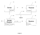
- FIG. 1 is a high-level diagram of a communication system that employs FEC encoding according to embodiments of the present invention.
- FIG. 2 shows a communication system like that of FIG. 1 , but having multiple senders and receivers.
- FIG. 3 illustrates an example of hardware that might be used to implement a sender and/or receiver.
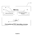
- FIG. 4 illustrates a conventional FEC decoding process
- FIG. 5 illustrates an embodiment of an in-place FEC decoding process according to the present invention.
- FIG. 6 is a flowchart of a transformation process according to an embodiment of the present invention.
- FIG. 7 is a flowchart of a method of in-place decoding of systematic Reed-Solomon codes.
- FIG. 8 is a flowchart further illustrating the method of in-place decoding of systematic Reed-Solomon codes.
- FIG. 9 is a flowchart of a method of vector calculation.
- FIG. 10 is a flowchart of a method of vector calculation.
- FIG. 11 illustrates a matrix usable for decoding.
- FIG. 12 illustrates a matrix and a transformation thereof.
- FIG. 13 illustrates data structures usable for processing.
- FIG. 14 illustrates a matrix and a transformation thereof.
- FIG. 15 illustrates a matrix and transformations thereof.
- FIG. 16 illustrates a matrix and a transformation thereof.
- FIG. 17 is a flowchart of a method.
- FIG. 18 is a flowchart of a method.
- FIG. 19 is a flowchart of a method.
- FIG. 20 is a flowchart of a method.
- FIG. 21 is a flowchart of a method.
- FIG. 22 is a flowchart of a method.
- FIG. 23 is a flowchart of a method.
- FIG. 24 is a flowchart of a method.
- in-place transformations Processes that substantially use the same memory for storing the received data and the decoded source block are often referred to as in-place transformations. Often times, the use of in-place transformations leads to a decrease in the running time of a particular process, as the process will spend less time accessing memory. This is particularly important because if the total size of the stored data is too large, then the processing unit may be forced to access secondary, slower, storage devices.
- Embodiments of the present invention use methods and processes for performing in-place linear transformations without requiring the use of extensive additional memory. These methods and processes are particularly applicable to FEC (forward error correction) encoding and decoding transformations of source blocks.
- FEC forward error correction
- FIG. 1 A high-level diagram of a communication system that employs FEC encoding at a sender 110 and FEC decoding at a receiver 140 is shown in FIG. 1 . It should be understood that sender 110 and receiver 140 could comprise a wide range of devices. In many embodiments, the sender and receiver are contained within a single transceiver device and two or more such devices can communicate among themselves.
- the sender 110 includes an FEC encoder 120 that is used to add protection to data that is sent over a communications channel 130 to receiver 140 that includes an FEC decoder 150 .
- Sender 110 may send the data generated by FEC encoder 120 in packets, e.g., Internet Protocol (IP) packets or other form of packets, that include identifying information in each packet that allow receiver 140 to determine how the data in that packet was generated and/or what portion of the sent data it represents.
- IP Internet Protocol
- Channel 130 may be a network channel, wireless channel, PSTN channel, or other channel.
- channel 130 will have some constraints under which, for some conditions, data is lost.
- a packet network if a portion of a received packet is not readable, the entire packet is discarded. Thus, there are situations wherein a packet sent from sender 110 is not deemed received at receiver 140 , so mechanisms are needed to recover from such losses.
- Receiver 140 provides FEC decoder 150 with as many as necessary of the received packets, and FEC decoder 150 recovers all or parts of the data.
- FEC forward error correction
- Receiver 140 provides FEC decoder 150 with as many as necessary of the received packets, and FEC decoder 150 recovers all or parts of the data.
- FEC forward error correction
- Receiver 140 provides FEC decoder 150 with as many as necessary of the received packets, and FEC decoder 150 recovers all or parts of the data.
- FEC forward error correction
- Receiverors provides for mechanisms that are provided in advance on the forward channel to allow for error correction if it occurs. Errors are not required, in which case the FEC efforts are just a backup, and in some cases, more errors might occur than can be recovered using FEC, in which cases the communication fails or a side communication occurs where retransmission, etc. are requested.
- FIG. 2 shows a system including a sender 210 , receivers 230 , 240 and a sender/receiver 220 , each including an FEC encoder ( 211 ), an FEC decoder ( 232 , 242 ), or both ( 222 , 221 ).
- all the senders, sender/receivers and receivers can communicate over a channel 250 , which could include an integrated IP network, a combination of disjoint networks, or other similar combinations of networks.
- FIG. 3 illustrates an example of hardware that might be used to implement a sender and/or receiver, in more detail.
- an FEC encoder/decoder 305 includes a CPU 310 that is used for performing operations, a cache 320 that provides temporary memory with very fast access for the CPU 310 , a RAM 330 that provides a larger amount of memory with relatively fast access for the CPU 310 , and disk 340 that provides a large amount of permanent memory with reasonable access speeds for the CPU 310 .
- the cache 320 may be partitioned into a portion that is controlled by the Operating System (OS) and a part that is under the control of the FEC encoding/decoding process, to preload data from other memory devices in order to prepare for processing by the CPU, i.e., Direct Memory Access (DMA) operations.
- OS Operating System
- DMA Direct Memory Access
- there may be more than one level of cache there may be other types of storage devices such as FLASH, and some of the storage types may be missing, e.g., disk storage.
- a computing device that has memory often has varying classes of memory. Some classes of memory are deemed “closer” than others in that closer memory might be physically closer to the processor or have a faster response rate, which allows a processor to read and/or write the memory faster than a memory that is farther away, requiring longer leads, or is slower. Even more generally, one class of memory can be preferred over another class because of latency, response rate, amount of energy needed to read/write locations of the memory, amount of energy to sustain the information in the memory, cost per bit and other considerations.
- the classes of memory can typically be ordered by preference, with the fastest, most power efficient memory being preferred. Typical engineering and design constraints may dictate the use of multiple classes of memory. For example, one might not want only RAM cache memory, because then no permanent storage is possible and one might not want only disk memory, because then processor access is slow.
- a device can have different classes of memory, with the classes ordered by preference.
- memory management might be required, such as swapping out to a less preferred class of memory.
- Such operations add overhead in terms of latency, computational cost, power usage, especially in certain devices and for certain operations, and therefore methods and apparatus described herein for efficient in-place transformations provide great benefit to operations of the device.
- FEC encoder/decoder 305 might control various memory units and there may be other parts that are under the control of the application that is using the FEC encoder/decoder 305 .
- the application may control its own copy of the source block to be encoded, and the FEC encoder may have its own copy of the source block passed to it by the application in a separate memory location.
- the FEC encoder may be important to minimize the memory used by the FEC encoder irrespective of the other memory used by the application, and it also may be the case in this example that the FEC encoder can overwrite portions of or all of the source block during its computation of the repair symbols for the source block since the application has its own separate copy of the source block and/or since the application may have already sent part of the source block to the channel and no longer needs to keep copies of these parts of the source block.
- generally during FEC decoding it is unimportant to maintain copies of encoding symbols once they have been used to recover the original source symbols of the source block.
- FIG. 4 illustrates a conventional FEC decoding process 410 (perhaps implemented as program code) that might use a CPU 405 to generate a source block of source symbols 430 from received encoding symbols 440 stored in a memory 420 , where memory 420 may include types shown in FIG. 3 or other types.
- memory 420 may include types shown in FIG. 3 or other types.
- the amount of memory needed by the FEC decoding process 410 for symbol storage is typically the total size of the source block plus the total size of the encoding symbols. Similar comments hold for conventional FEC encoding processes.
- FIG. 5 illustrates an embodiment of an in-place FEC decoding process according to the present invention.
- the snapshot of the In-Place FEC Decoding Process at start 510 shows a CPU 505 to process received encoding symbols 530 stored in memory 520 , where memory 520 may include types shown in FIG. 3 or other types.
- the snapshot of the In-Place FEC Decoding Process at finish 515 shows the CPU 505 that was used to produce the recovered source symbols of the source block 540 stored in the same memory 520 as originally occupied by the received encoding symbols 530 .
- the memory used for symbols is a small amount larger than the maximum of the amount of memory needed to store the received encoding symbols 530 and the amount of memory needed to store the recovered source symbols 540 .
- the in-place FEC decoding process 510 and 515 uses around one-half the memory of a conventional FEC decoding process 410 for symbol storage during decoding. Similar comments hold for in-place FEC encoding processes.
- a ring is a set on which two operations, addition and multiplication, are defined such that these operations satisfy the distributive laws.
- the set considered with addition alone forms an abelian group, i.e., the result of an addition is independent of the ordering of the summands, there is a neutral element 0 for addition, and for each element there is another element such that the sum of these elements is 0.
- the other requirement is that the multiplication has a neutral element 1, such that multiplication of any element with 1 does not change the value of that element.
- symbol refers to a piece of data that is typically smaller than the source block.
- the size of a symbol can often be measured in bits, where a symbol has the size of M bits and the symbol is selected from an alphabet of 2 M symbols.
- the size of a symbol could be equal to the packet size, or it could be smaller, so that each packet contains one or more symbols.
- a mapping (symbol-wise sum) is a logical construct implementable in hardware and/or software, etc. that maps pairs of symbols of the same size to another symbol of that size. We denote this mapping by “ ⁇ ”, and the image of this map on the pair (S, T) of symbols by S ⁇ T.
- An example of such a mapping is the bit-wise exclusive-or (XOR).
- A is a set equipped with a commutative addition operation “+” that has a neutral element and that, for every element, contains its additive inverse.
- An “action” of this group on the set of symbols is a mapping that maps a pair, comprising a group element r and a symbol S, to another symbol.
- the field GF( 4 ) consists of four elements 0, 1, 2, 3, wherein addition is the normal XOR of integers, and multiplication is defined via Table 1.
- K is an extension field of GF( 2 ) of degree d
- an operation of the field can be defined on symbols whose size is divisible by d.
- Such an operation is described in Bloemer, et al., “An XOR-Based Erasure Resilient Coding Scheme”, published as Technical Report Number TR-95-048 of the International Computer Science Institute in Berkeley, Calif. (1995).
- This scheme uses the so-called “regular representation” of the field K as d ⁇ d matrices with binary entries.
- a linear transformation can be defined with reference to the concept of an operation of a ring on symbols. For given integers m and n, a linear transformation induced by the operation maps vectors of n symbols into vectors of m symbols using the space of matrices with entries in the specified ring.
- a matrix over the ring R is a 2-dimensional collection of entries, whose entries belong to R. If a matrix has m rows and n columns, then it is commonly referred to as an m ⁇ n matrix.
- the pair (m,n) is called the “format” of the matrix. Matrices of the same format can be added and subtracted, using the addition and subtraction in the underlying field or ring.
- a matrix of format (m,n) can be multiplied with a matrix of format (n,k) as is commonly known, yielding a matrix of format (m,k).
- B[j,k] denotes the entry of B at position (j,k)
- this matrix transforms the vector (S[ 1 ], S[ 2 ], . . . , S[n]), and if (X[ 1 ], X[ 2 ], . . . , X[m]), denotes the transformed vector
- S when using a linear code to encode a piece of data, or source block, S could be the source symbols of the source block to be encoded, X could be the encoded version of S, and B could be a generator matrix for the code.
- X could be the redundant symbols of the encoding of S, while B could be the matrix describing the dependency of the redundant symbols on the source symbols.
- S could be a vector of symbols obtained from a set of symbols received after transmission, and X could correspond to a set of symbols that are either completely or partially unknown, and B could describe the relationship between X and S.
- Step 610 the integer variable i is initialized to zero.
- Step 620 the value of i is increased to next(i), where next(i) is the smallest integer greater than i such that row next(i) of B has at least one non-zero entry, and next(i) is set to m+1 if all rows beyond row i have all zero entries.
- Step 630 it is checked whether or not i>m, and if i>m then processing stops at Step 640 , but if i ⁇ m then processing proceeds to Step 650 where a temporary symbol value Tis set to zeroes and the integer variable j is set to zero.
- Step 660 the value of j is increased to next (i,j), where next (i,j) is the smallest integer>j such that in row i of B, B[i,next(i,j)] is a non-zero entry, and next (i,j) is set to n+1 if all entries beyond B[i,j] row i are all zeroes.
- Step 670 it is checked whether or not j>n, and if j>n then processing proceeds to Step 680 where symbol S[i] is set to T and then processing returns to Step 620 . If j ⁇ n in Step 670 then processing proceeds to Step 690 where temporary symbol value T is reset to T ⁇ B[i,j]*S[j] and then processing returns to Step 660 .
- B be a matrix with format (m,n) and let S be a column vector of n symbols.
- Step 710 the integer variable i is initialized to m+1.
- Step 720 the value of i is decreased to prev(i), where prev(i) is the largest integer ⁇ i such that row prev(i) of B has at least one non-zero entry, and prev(i) is set to zero if all rows before row i have all zero entries.
- Step 730 it is checked whether or not i ⁇ 1, and if i ⁇ 1 then processing stops at Step 740 , but if i ⁇ 1 then processing proceeds to Step 750 where a temporary symbol value T is set to zeroes and the integer variable j is set to zero.
- Step 760 the value of j is increased to next(i,j), where next(i,j) is the smallest integer>j such that in row i of B, B[i,next(i,j)] is a non-zero entry, and next(i,j) is set to n+1 if all entries beyond B[i,j] row i are all zeroes.
- Step 770 it is checked whether or not j>n, and if j>n then processing proceeds to Step 780 where symbol S[i] is set to T and then processing returns to Step 720 . If j ⁇ n in Step 770 then processing proceeds to Step 790 where temporary symbol value T is reset to T ⁇ B[i,j]*S[j] and then processing returns to Step 760 .
- the matrix ⁇ tilde over (B) ⁇ is the matrix derived from B as follows:
- B is a permutation matrix of format (n,n), i.e., it has exactly one nonzero entry in each row and each column and the nonzero entries are 1. Since this matrix is sparse, i.e., it has very few entries that are nonzero, in many applications it is desirable to represent it not as a matrix, but as a list (or another object that uses less memory than a matrix). For example, B could be represented as a list (B[ 1 ], . . . , B[n]) wherein (j,B[j]) are the positions of the nonzero entries of B.
- Step 805 a variable c is set to zero. This variable counts how many of the positions of the array corresponding to B have already been visited.
- Step 835 a test is made to see whether d is equal to c. If so, no further operation is necessary and processing jumps to Step 860 . The value v[c] is set to 1, and the counter c is incremented by one in Step 860 . If d is not equal to c in Step 835 , then the values of T and S[c] are swapped in Step 840 .
- Step 845 the values of T and S[d] are swapped in Step 845 , v[d] is set equal to 1, and d is set to B[d].
- Step 850 it is checked to see if the value of d is equal to c, and if this is false then the loop comprising Steps 845 and 850 is repeated again. If d is equal to c, then processing jumps out of the loop and the values of T and S[c] are swapped in Step 855 .
- Step 860 the value of v[c] is set to 1, and the whole process now returns to Step 810 , in which c is incremented by one. In effect, the process described decomposes the permutation given by the matrix B in cycles, and finds and processes the cycles one-by-one.
- the process described above can be applied to p[ 1 ], . . . , p[n] to recompute the logical to memory mapping of S in place of applying it to S[ 1 ], . . . , S[n] as described above.
- the variable T used to describe the process in FIG. 8 is used to temporarily store a value of p[c] instead of a symbol S[c], and whatever logic is applied to the vector of symbols S[ 1 ], . . . , S[n] in FIG. 8 is instead applied to the vector p[ 1 ], . . . , p[n].
- This representation can be advantageous, because generally it is less costly in terms of CPU, memory bandwidth and other resources to move around in memory the typically much smaller entries of p[ 1 ], . . . , p[n] than the typically much larger symbol entries S[ 1 ], . . . , S[n].
- B is a matrix of format (n,n) with exactly one nonzero entry in every row and every column.
- a permutation matrix is a special case of a monomial matrix.
- a process to compute an in-place transformation for a monomial matrix is now described, with reference to FIG. 9 .
- Such a matrix can be succinctly described by a list (B[ 1 ], . . . , B[n]; ⁇ [ 1 ], . . . , ⁇ [n]), wherein for all relevant values of j, B[j] is the position of the nonzero element in row j of B, and ⁇ [j] is the value of that nonzero position.
- the process to calculate the in-place transformation pertaining to B uses the process for calculating a linear transformation pertaining to the permutation part of B as a sub-process.
- Step 905 of FIG. 9 the process calculates C ⁇ circle around ( ⁇ ) ⁇ S using the process described in FIG. 8 , wherein C is the permutation matrix obtained from the matrix B by replacing the nonzero entries of B by 1.
- an integer variable i is initialized to zero, and then in Steps 920 , 940 and 950 a loop is executed where in for each value of i between 1 and n the value of S[i] is replaced by the operation of ⁇ [i] on that position, i.e., by ⁇ [i]*S[i].
- Step 930 processing stops in Step 930 .
- the process described with reference to FIG. 9 calculates B ⁇ circle around ( ⁇ ) ⁇ S, since B can be written as a product of a diagonal matrix with diagonal entries ⁇ [ 1 ], . . . , ⁇ [n], and the matrix C. Furthermore, the storage used for symbols during the process is n+1.
- both L ⁇ S and ⁇ tilde over (L) ⁇ S are sparse computations, i.e., both the multiplication by L and multiplication by the inverse of L can be accomplished by a sparse in-place computation, even though L ⁇ 1 is not necessarily a sparse matrix.
- B is a product of matrices of the types described above, i.e., B is a product M 1 •M 2 • . . . •M t , where each M j is either a permutation matrix, or a monomial matrix, or an upper triangular matrix, or a lower triangular matrix.
- the process to calculate the transformation in-place for this matrix is to transform S with M t , then transform the result with M t-1 , etc.
- a decomposition of B into a product of three matrices P, L, and U, wherein P is a permutation matrix, L is a lower triangular matrix with ones on the main diagonal, and U is an upper triangular matrix.
- P is a permutation matrix
- L is a lower triangular matrix with ones on the main diagonal
- U is an upper triangular matrix.
- Such a decomposition can be calculated by a variety of processes as is known to those of skill in the art.
- One of these processes is the well-known Gaussian elimination process.
- the in-place transformation of S by B i.e., computing B ⁇ circle around ( ⁇ ) ⁇ S using an in-place transformation, is simply P ⁇ circle around ( ⁇ ) ⁇ (L ⁇ (U ⁇ S))
- Step 1010 a PLU-decomposition of B is calculated.
- a decomposition can be calculated by a variety of means.
- general matrices one possible method uses the Gaussian elimination algorithm.
- special matrices e.g., sparse matrices, Cauchy matrices, etc.
- more efficient methods can be employed, as is known to those of skill in the art.
- the in-place transformation U ⁇ S of the vector S of symbols is computed, as described with reference to FIG. 6 .
- Step 1030 the transformed set of symbols S is transformed again, this time computing the in-place transformation L ⁇ S, as described with reference to FIG. 7 .
- Step 1040 the new transformed set of symbols S is transformed again, computing the in-place transformation of S by permutation matrix P, described with reference to FIG. 8 .
- both B ⁇ circle around ( ⁇ ) ⁇ S and B ⁇ 1 ⁇ circle around ( ⁇ ) ⁇ S can be computed as described using the in-place transformations described above in linear time.
- the amount of memory or storage used during the computation of the in-place transformations described above for storing symbols at any point in the computation is n+1.
- a matrix B of format (m,n) is not a square matrix, then methods similar to the ones described above can be utilized to calculate the transformations in such a way as to minimize the amount of memory. For example, when the matrix has more rows than columns (i.e., m is larger than n), then it is only important to calculate the first n elements of the result vector in-place. This can be accomplished as follows.
- B′ identify the square matrix formed by the first n rows of B
- B′′ identify the matrix formed by the last m-n rows of B.
- S be a column vector of n symbols that initially holds the symbol values to be transformed, and let S′ identify a column vector of an additional m-n symbols. Then, B ⁇ circle around ( ⁇ ) ⁇ S can be computed in-place as follows:
- n is larger than m
- a similar method can be used to calculate the transformation in such a way that it replaces the first m entries of the vector S as follows.
- B′ identify the square matrix formed by the first m columns of B
- B′′ identify the matrix formed by the last n-m columns of B.
- S be a column vector of n symbols that initially holds the symbol values to be transformed, and let S′ identify the first m symbols of S and let S′′ identify the last n-m symbols of S.
- B ⁇ circle around ( ⁇ ) ⁇ S can be computed in-place as follows:
- M be a square matrix of format (n,n) of the type shown in FIG. 11 .
- L is a lower triangular invertible matrix of format (m,m)
- A is a matrix of format (m,n-m)
- B is a matrix of format (n-m,m)
- C is an invertible matrix of format (n-m,n-m).
- the computation needed to perform the in-place transformations described below that compute M ⁇ circle around ( ⁇ ) ⁇ S and M ⁇ 1 ⁇ circle around ( ⁇ ) ⁇ S is of the order of n symbol operations, whereas the total space or memory used for symbols during the computation is at most n+1.
- M′ be the square matrix of format (n,n) derived from M as shown in FIG. 12 .
- L and B are the same matrices as L and B shown in FIG. 11 , all entries of the matrix formed by the last n-m columns and the first m rows are zeroes, and the matrix formed by the last n-m columns and the last n-m rows is the identity matrix.
- M′ is an invertible lower triangular matrix.
- FIG. 12 also shows the form of M′ ⁇ 1 , the inverse matrix of M′.
- D be the matrix of format (n,n-m) shown in FIG. 13A .
- the matrix D can also be viewed as a column vector of n symbols, where each symbol is the concatenation of n-m field elements from the underlying field K.
- n symbols each symbol is the concatenation of n-m field elements from the underlying field K.
- This factorization can be obtained for example using well-known Gaussian elimination or similar techniques.
- L′ be a square matrix of format (n,n) as shown in FIG. 14 .
- L is the same matrix as the matrix L shown in FIG. 11 , all entries of the matrix formed by the last n-m columns and the first m rows are zeroes, all entries of the matrix formed by the last n-m rows and the first m columns are zeroes, and the matrix formed by the last n-m columns and the last n-m rows is the identity matrix.
- L′ is an invertible lower triangular matrix.
- FIG. 14 also shows the form of L′ ⁇ 1 , the inverse matrix of L′.
- P′, ⁇ ′ and Y′ be a square matrices of format (n-m, m) as shown in FIGS. 15A , 15 B and 15 C, respectively.
- P′, ⁇ ′ and Y′ are invertible matrices.
- N′ be a square matrix of format (n,n) as shown in FIG. 16 .
- L and A are the same matrices L and A as shown in FIG. 11 , all entries of the matrix formed by the last n-m rows and the first m columns are zeroes, and the matrix formed by the last n-m columns and the last n-m rows is the identity matrix.
- N′ is an invertible matrix, and although it is not literally lower triangular, it can be seen that N′ ⁇ S computes in-place the result of N′ ⁇ circle around ( ⁇ ) ⁇ S.
- FIG. 16 also shows the form of N′ ⁇ 1 , the inverse matrix of N′. It can also be verified that ⁇ ′ ⁇ S computes in-place the result of N′ ⁇ 1 ⁇ circle around ( ⁇ ) ⁇ S.
- Step 1710 the in-place transformation N′ ⁇ S is computed.
- Step 1730 the matrix F is factored into P, ⁇ , and Y as described above.
- Step 1740 the in-place transformation Y′ ⁇ S is computed.
- Step 1750 the in-place transformation ⁇ ′ ⁇ S is computed.
- Step 1760 the in-place transformation P ⁇ circle around ( ⁇ ) ⁇ S is computed.
- Step 1770 the in-place transformation ⁇ tilde over (L) ⁇ ′ ⁇ S is computed.
- Step 1780 the in-place transformation M′ ⁇ S is computed.
- Step 1790 the process stops as the in-place transformation is completed.
- the vector S stores the result of M multiplied by the original vector S. Note that the storage used for symbols at any point in this process is at most n+1, and that the number of symbol operations aggregated over all the steps is linear in the sum of the number of non-zero entries in M and (n-m) 2 .
- Step 1770 between Step 1730 and Step 1740 is to perform Step 1770 between Step 1740 and Step 1750 , in which case it is possible to combine Steps 1740 and 1770 into one in-place transformation as shown in FIG.
- Steps 1730 , 1740 , 1750 and 1760 can be replaced with the steps of multiplying F by the column vector comprising the last n-m symbols of S and replacing the last n-m symbols of S by the result.
- the multiplication by F may be for example performed using either in-place transformations as described in this disclosure or standard techniques such as standard matrix multiplication.
- FIG. 18 Based on the notation introduced above, another variant of a process that computes the in-place transformation M ⁇ circle around ( ⁇ ) ⁇ S on input M and S is described with reference to FIG. 18 .
- the in-place transformation described with reference to FIG. 18 uses a total of n+(n-m)+1 symbols of storage, i.e., n-m more symbols than the process described with reference to FIG. 17 , with the benefit that the total number of symbol operations is the same as would be used in a straightforward non-in-place calculation of M ⁇ circle around ( ⁇ ) ⁇ S.
- the process described below with reference to FIG. 18 may take less computation than the process described with reference to FIG. 17 , at the expense of slightly more symbol storage.
- n-m is often small compared to n, and thus the extra amount of symbol storage required for the process described with reference to FIG. 18 is typically small compared to the minimal amount of symbol storage achieved by the process described with reference to FIG. 17 .
- W be a column vector of an additional n-m symbols.
- Q identify the matrix of format (m,n) that comprises the first m rows of M
- Q′ identify the matrix of format (n-m,n) that comprises the last n-m rows of M.
- the in-place transformation Q ⁇ S is computed. Note that because the first m columns of Q form the lower triangular matrix L, the in-place transformation computed in Step 1820 results in the first m entries of S being equal to Q ⁇ circle around ( ⁇ ) ⁇ S.
- W is copied into the last n-m symbols of S.
- Step 1840 the process stops as the in-place transformation is completed.
- Step 1910 the in-place transformation ⁇ tilde over (M) ⁇ ′ ⁇ S is computed.
- Step 1920 the in-place transformation L′ ⁇ S is computed.
- Step 1940 the matrix F is factored into P, ⁇ , and Y as described above.
- Step 1950 the in-place transformation P′ ⁇ 1 ⁇ circle around ( ⁇ ) ⁇ S is computed.
- Step 1960 the in-place transformation ⁇ tilde over ( ⁇ ) ⁇ ′ ⁇ S is computed.
- Step 1970 the in-place transformation ⁇ tilde over (Y) ⁇ ′ ⁇ S is computed.
- Step 1980 the in-place transformation ⁇ ′ ⁇ S is computed.
- Step 1990 the process stops as the in-place transformation is completed.
- the vector S stores the result of M ⁇ 1 multiplied by the original vector S. Note that the storage used for symbols at any point in this process is at most n+1, and that the number of symbol operations aggregated over all the steps is linear in the sum of the number of non-zero entries in M and (n-M) 2 .
- Steps 1940 , 1950 , 1960 and 1970 can be replaced with the steps of determining F ⁇ 1 and then multiplying F ⁇ 1 by the column vector comprising the last n-m symbols of S and replacing the last n-m symbols of S by the result.
- the determination of and multiplication by F ⁇ 1 may be for example performed using either in-place transformations as described in this disclosure or standard techniques such as standard Gaussian elimination and matrix multiplication.
- more storage for symbols may be required, for example an additional n-m symbols of storage so that for example the maximum storage for symbols during the in-place transformation is 2 ⁇ n-m+1 symbols, but still the overall amount of storage used for symbols during the entire in-place transformation is substantially less than 2 ⁇ n that standard techniques would use, especially when m is close to n.
- a class of linear codes for protection of transmission in case of erasures, or corruptions are known as Reed-Solomon codes.
- codes There are a number of equivalent ways to describe these codes, such as cyclic codes, codes based on Vandermonde matrices, codes based on Cauchy matrices, or the like. In all these cases, the encoding process can be described by multiplication of a vector of symbols with a matrix.
- M′ identify the matrix of format (k,k) that comprises the first k rows of M
- w′ identify the first k symbols in w and let w′′ identify the last r symbols in w.
- M′ is the identity matrix.
- the entries of an encoded vector w′ are referred to as the source positions.
- M′′ is used for calculating the r redundant symbols w′′.
- the matrix M can be represented in a variety of ways. For example, where a non-systematic version is desired, M could be a Vandermonde matrix. In the systematic case, M′′ could form a Cauchy matrix.
- the process described with reference to FIG. 20 describes an in-place transformation that produces the encoding using storage for at most n+1 symbols during the process.
- w′ stores the k source symbols to be encoded.
- w′′ stores the remaining r encoding symbols generated.
- w′′ is computed as M′′ ⁇ circle around ( ⁇ ) ⁇ w′ using a straightforward matrix multiplication, for example using the “simple transformation process” described previously.
- a decomposition can be calculated with a variety of approaches, for example, using the Gaussian elimination algorithm, or, when the matrix M′ is a Cauchy matrix, then this PLU-decomposition can be calculated with a formula, thereby reducing the computational complexity of the computation.
- the in-place transformation U ⁇ w′ is computed.
- Step 2040 the in-place transformation L ⁇ w′ is computed.
- Step 2050 the in-place transformation P ⁇ circle around ( ⁇ ) ⁇ w′ is computed.
- Step 2060 the processing stops because the in-place transformation is complete. It should be noted that the order in which encoding symbols are sent in any given system need not be the order in which they are stored and so it may not be necessary to actually perform the last step 2060 .
- the process herein described with reference to FIG. 21 can be used to generate the redundant symbols using an in-place transformation that uses at most k+1 symbols of storage.
- B be the matrix of format (r,r) that is identical with the first r columns of M′′
- B′ be the matrix of format (r,k ⁇ r) that is identical with the last k ⁇ r columns of M′′.
- Step 2120 the in-place transformation U ⁇ v is computed.
- Step 2130 the in-place transformation L ⁇ v is computed.
- Step 2140 the in-place transformation P ⁇ circle around ( ⁇ ) ⁇ v is computed.
- Step 2150 v is updated to v ⁇ B′ ⁇ circle around ( ⁇ ) ⁇ v′ using a small variant of a straightforward matrix multiplication such as the “simple transformation process” described in the section above titled “Linear Operators”.
- Step 2160 the processing stops because the in-place transformation is complete.
- the phrase “sufficiently many symbols” may translate to as few as k symbols, or more than k symbols, depending on the application and on the computational and storage resources available for decoding.
- Step 2205 identifies the erased source symbol positions denoted by p[ 1 ], . . . , p[e] with respect to the columns of matrix M′′
- Step 2210 identifies the positions r[ 1 ], . . . , r[e] of the redundant symbols received with respect to the rows of matrix M′′.
- the received symbols are stored in a column vector v of k symbols, where the symbols in positions p[ 1 ], . . .
- Steps 2220 through 2250 effectively running these steps for values of i between 1 and the number e of erased source positions.
- the value of i is initialized to 1 in Step 2215 .
- the loop in Steps 2225 through 2240 goes over values of j between 1 and k, not equal to any of the p[ 1 ], . . . , p[e], and for each such j updates v[p[i]] by adding its value with the value of M′′[r[i],j]*v[j].
- Such a PLU-decomposition can be calculated with a variety of approaches, for example, using the Gaussian elimination algorithm, or, when the matrix M′′ is a Cauchy matrix, then this PLU-decomposition can be calculated with a formula, thereby reducing the computational complexity of the computation.
- the PLU-decomposition of T may be calculated directly by this process without necessarily explicitly calculating the matrix T.
- the in-place transformation U ⁇ z is calculated using the process described in FIG. 6 .
- L ⁇ z is calculated using the process in FIG. 7 .
- the in-place transformation P ⁇ circle around ( ⁇ ) ⁇ z is calculated using the process in FIG. 8 .
- Step 2340 the process stops because the in-place decoding for Reed-Solomon codes is complete.
- the overall in-place transformation described with reference to FIG. 23 uses storage for at most k+1 symbols during the processing.
- Reed-Solomon codes are for demonstrative purposes only and is not intended to limit the scope of this invention. More generally, very similar methods can be applied to the in-place decoding of similar classes of codes, such as Algebraic-Geometric codes (AG-codes, for short), BCH codes, or any other class of codes for which generator matrices are known explicitly.
- AG-codes Algebraic-Geometric codes
- BCH codes BCH codes
- the column vector z of r redundant symbols is constructed as follows from the column vector v of k source symbols: a matrix A is chosen of format (r,k), and another matrix U is chosen of format (r,r) that is a sparse upper or lower triangular matrix.
- the computed redundant symbols have a very non-regular dependency on the source symbols, e.g., the last redundant symbol in z is the XOR of 3 of the source symbols in v, the second to last redundant symbol in z is the XOR of 6 of the source symbols in v, etc.
- P is a permutation matrix
- L is a lower triangular matrix
- Y is an upper triangular matrix
- A′ P ⁇ L ⁇ Y.
- Step 2420 the in-place transformation Y ⁇ v′ is computed
- Step 2430 the in-place transformation L ⁇ v′ is computed
- Step 2440 the in-place transformation P ⁇ circle around ( ⁇ ) ⁇ v′ is computed.
- Step 2460 the in-place transformation ⁇ v′ is computed.
- Step 2470 computation stops with the resulting r redundant symbols stored in the first r symbols of v, i.e., in v′.
- Steps 2410 , 2420 , 2430 and 2440 can be replaced with a more sophisticated approach such as that disclosed in U.S. Pat. No. 6,856,263 entitled “Systems and Processes for Decoding Chain Reaction Codes Through Inactivation,” (hereinafter “Inactivation Decoder”) to write the matrix A in a form similar to that shown in FIG. 11 and then use a variation on the process described with reference to FIG. 17 to compute A ⁇ circle around ( ⁇ ) ⁇ v using an in-place transformation. For example if A is a square matrix, i.e.
- a ⁇ circle around ( ⁇ ) ⁇ v can be used to compute A ⁇ circle around ( ⁇ ) ⁇ v, thereby using the 3 ⁇ k symbol operations, i.e., the same number of symbol operations as would be used to compute A ⁇ circle around ( ⁇ ) ⁇ v in a straightforward way, but using storage for only 1.14 ⁇ k symbols.
- the number r of redundant symbols is zero for some embodiments of chain reaction codes, whereas for other embodiments the number r of redundant symbols is greater than zero.
- the rows of T correspond to dynamic output symbols and to the redundant (pre-coding) symbols
- x is a vector of n symbols with initially unknown values that are to be solved for, comprising the source symbols and the redundant (pre-coding) symbols
- z is a vector of s symbols with known values comprising the received symbols and the check symbols of the pre-code.
- the check symbols have value 0, while in others this value may be different from 0. No matter how the check symbol values are set, they are known to the decoder either through prior communication between the encoder and the decoder or by other steps.
- the matrix L is a lower triangular binary matrix of format (m,m), and A, B, and C are matrices of appropriate sizes; in preferred applications A and L may be a sparse matrices, i.e., they may not have many non-zero positions.
- Tasks (a) and (c) are described above in a prior section herein, for example the process described with reference to FIG. 8 is one way to perform tasks (a) and (c) using an in-place transformation.
- M has s rows instead of the n rows shown in FIG. 11 .
- a first step in the current embodiment is to determine n rows of M that together form a matrix of rank n and then redefine M to be the resulting full rank square matrix of format (n,n).
- the remaining steps in the current embodiment is to perform the process described previously with reference to FIG. 19 , referring to FIG. 1 , FIG. 12 , FIG. 13A , FIG. 13B , FIG. 14 , FIG. 15 and FIG. 16 .
- the submatrices L, A, B and C can be determined incrementally as the process proceeds using for example the methods described in “Inactivation Decoder”.
- a variant of the process described in Steps 1910 and 1930 of FIG. 19 can be performed using the methods described in “Inactivation Decoder” to incrementally form the matrices and perform the equivalent of the steps described in Steps 1910 and 1930 of FIG. 19 .
- the n rows of M that have rank n have been determined and these rows of M have been logically manipulated into the form shown in FIG. 11 .
- the remainder of the steps shown in FIG. 19 can then be applied in the appropriate order to complete the in-place transformation process.
- T is a full rank matrix of format (n,n) with rows corresponding to source symbols and to the redundant (pre-coding) symbols
- x is a vector of intermediate symbols with initially unknown values that are to be solved for
- z is a vector of n symbols with known values, corresponding to the source symbols and the check symbols of the pre-code.
- the method described in Shokrollahi I performs a series of steps to obtain all the source symbols from any combination of some of the source symbols, and some output symbols generated by the systematic encoder.
- all the received symbols comprising some of the source symbols and the other output symbols are collected and decoded to obtain a set of intermediate symbols.
- the intermediate symbols are transformed to obtain the missing source symbols.
- the in-place calculation of the intermediate symbols from the received symbols is the same as described above under the heading “In-place Decoding of Chain Reaction Codes”. In this section, we will describe the in-place calculation of the source symbols from the intermediate symbols.
- T is a matrix of format (n,n) that is full rank and S is a column vector of the n intermediate symbols.
- An embodiment of an in-place transformation that computes T ⁇ circle around ( ⁇ ) ⁇ S is the process described with reference to FIG. 17 , that also refers to FIG. 11 , FIG. 12 , FIG. 13A , FIG. 13B , FIG. 14 , FIG. 15 , FIG. 16 and FIG. 17 .
- This embodiment uses storage for n+1 symbols at most during the process.
- the variations of the process described with reference to FIG. 17 also apply to this embodiment.
- a second embodiment of an in-place transformation that computes T ⁇ circle around ( ⁇ ) ⁇ S is the process described with reference to FIG. 18 .
- This embodiment uses storage for n+(n-m)+1 at most during the process.
- n-m is small relative to the value of n, and thus the relative size of the symbol storage used during the process is slightly larger than n.
- the variations of the process described with reference to FIG. 18 also apply to this embodiment.
- Embodiments described above that compute intermediate symbols from received output symbols using in-place transformation processes and embodiments described above that compute source symbols from recovered input symbols using in-place transformation processes can be combined to provide overall embodiments that compute source symbols from received output symbols using in-place transformations, where the storage for symbols used by the combination of such two processes is at most the storage for symbols used by either process individually.
- a linear transform process is a process of applying a linear transform to a plurality of input elements to derive a plurality of output elements.
- memory is allocated for storing the input elements that are available for the linear transform process and at least some of that memory is reused for storing the derived output elements.
- FEC coding can involve codes such as Reed-Solomon codes, chain reaction codes, multi-stage chain reaction codes or any other linear code.
- Logic for performing the transform can read input elements to generate output elements and reuse memory for used-up input elements for storing generated output elements (or intermediate elements, that then might be in turn used up).
Landscapes
- Engineering & Computer Science (AREA)
- Physics & Mathematics (AREA)
- Theoretical Computer Science (AREA)
- Probability & Statistics with Applications (AREA)
- Mathematical Physics (AREA)
- General Physics & Mathematics (AREA)
- Pure & Applied Mathematics (AREA)
- Mathematical Optimization (AREA)
- Mathematical Analysis (AREA)
- Computational Mathematics (AREA)
- Signal Processing (AREA)
- Computer Networks & Wireless Communication (AREA)
- Algebra (AREA)
- Data Mining & Analysis (AREA)
- Computing Systems (AREA)
- Databases & Information Systems (AREA)
- Software Systems (AREA)
- General Engineering & Computer Science (AREA)
- Error Detection And Correction (AREA)
- Compression, Expansion, Code Conversion, And Decoders (AREA)
- Compression Or Coding Systems Of Tv Signals (AREA)
Priority Applications (1)
| Application Number | Priority Date | Filing Date | Title |
|---|---|---|---|
| US11/423,376 US7644335B2 (en) | 2005-06-10 | 2006-06-09 | In-place transformations with applications to encoding and decoding various classes of codes |
Applications Claiming Priority (2)
| Application Number | Priority Date | Filing Date | Title |
|---|---|---|---|
| US68963205P | 2005-06-10 | 2005-06-10 | |
| US11/423,376 US7644335B2 (en) | 2005-06-10 | 2006-06-09 | In-place transformations with applications to encoding and decoding various classes of codes |
Publications (2)
| Publication Number | Publication Date |
|---|---|
| US20060280254A1 US20060280254A1 (en) | 2006-12-14 |
| US7644335B2 true US7644335B2 (en) | 2010-01-05 |
Family
ID=37532889
Family Applications (1)
| Application Number | Title | Priority Date | Filing Date |
|---|---|---|---|
| US11/423,376 Expired - Fee Related US7644335B2 (en) | 2005-06-10 | 2006-06-09 | In-place transformations with applications to encoding and decoding various classes of codes |
Country Status (6)
| Country | Link |
|---|---|
| US (1) | US7644335B2 (ja) |
| EP (1) | EP1894376A4 (ja) |
| JP (2) | JP5231218B2 (ja) |
| KR (1) | KR101270815B1 (ja) |
| CN (1) | CN101243664B (ja) |
| WO (1) | WO2006135878A2 (ja) |
Cited By (35)
| Publication number | Priority date | Publication date | Assignee | Title |
|---|---|---|---|---|
| US20070195894A1 (en) * | 2006-02-21 | 2007-08-23 | Digital Fountain, Inc. | Multiple-field based code generator and decoder for communications systems |
| US20080256418A1 (en) * | 2006-06-09 | 2008-10-16 | Digital Fountain, Inc | Dynamic stream interleaving and sub-stream based delivery |
| US20090019333A1 (en) * | 2007-07-02 | 2009-01-15 | Mcevoy Paul | Generation of parity-check matrices |
| US20090031199A1 (en) * | 2004-05-07 | 2009-01-29 | Digital Fountain, Inc. | File download and streaming system |
| US20090067551A1 (en) * | 2007-09-12 | 2009-03-12 | Digital Fountain, Inc. | Generating and communicating source identification information to enable reliable communications |
| US20090189792A1 (en) * | 2002-10-05 | 2009-07-30 | Shokrollahi M Amin | Systematic encoding and decoding of chain reaction codes |
| US20100103001A1 (en) * | 2002-06-11 | 2010-04-29 | Qualcomm Incorporated | Methods and apparatus employing fec codes with permanent inactivation of symbols for encoding and decoding processes |
| US20100211690A1 (en) * | 2009-02-13 | 2010-08-19 | Digital Fountain, Inc. | Block partitioning for a data stream |
| US20100223533A1 (en) * | 2009-02-27 | 2010-09-02 | Qualcomm Incorporated | Mobile reception of digital video broadcasting-terrestrial services |
| US20110019769A1 (en) * | 2001-12-21 | 2011-01-27 | Qualcomm Incorporated | Multi stage code generator and decoder for communication systems |
| US20110096828A1 (en) * | 2009-09-22 | 2011-04-28 | Qualcomm Incorporated | Enhanced block-request streaming using scalable encoding |
| US20110231519A1 (en) * | 2006-06-09 | 2011-09-22 | Qualcomm Incorporated | Enhanced block-request streaming using url templates and construction rules |
| US20110238789A1 (en) * | 2006-06-09 | 2011-09-29 | Qualcomm Incorporated | Enhanced block-request streaming system using signaling or block creation |
| US20110239078A1 (en) * | 2006-06-09 | 2011-09-29 | Qualcomm Incorporated | Enhanced block-request streaming using cooperative parallel http and forward error correction |
| US20110241911A1 (en) * | 2010-04-05 | 2011-10-06 | Samsung Electronics Co., Ltd. | Apparatus and method for channel encoding in a communication/broadcasting system |
| US8806050B2 (en) | 2010-08-10 | 2014-08-12 | Qualcomm Incorporated | Manifest file updates for network streaming of coded multimedia data |
| US8887020B2 (en) | 2003-10-06 | 2014-11-11 | Digital Fountain, Inc. | Error-correcting multi-stage code generator and decoder for communication systems having single transmitters or multiple transmitters |
| US8958375B2 (en) | 2011-02-11 | 2015-02-17 | Qualcomm Incorporated | Framing for an improved radio link protocol including FEC |
| US9136983B2 (en) | 2006-02-13 | 2015-09-15 | Digital Fountain, Inc. | Streaming and buffering using variable FEC overhead and protection periods |
| US9225961B2 (en) | 2010-05-13 | 2015-12-29 | Qualcomm Incorporated | Frame packing for asymmetric stereo video |
| US9246633B2 (en) | 1998-09-23 | 2016-01-26 | Digital Fountain, Inc. | Information additive code generator and decoder for communication systems |
| US9253233B2 (en) | 2011-08-31 | 2016-02-02 | Qualcomm Incorporated | Switch signaling methods providing improved switching between representations for adaptive HTTP streaming |
| US9264069B2 (en) | 2006-05-10 | 2016-02-16 | Digital Fountain, Inc. | Code generator and decoder for communications systems operating using hybrid codes to allow for multiple efficient uses of the communications systems |
| US9270299B2 (en) | 2011-02-11 | 2016-02-23 | Qualcomm Incorporated | Encoding and decoding using elastic codes with flexible source block mapping |
| US9288010B2 (en) | 2009-08-19 | 2016-03-15 | Qualcomm Incorporated | Universal file delivery methods for providing unequal error protection and bundled file delivery services |
| US9294226B2 (en) | 2012-03-26 | 2016-03-22 | Qualcomm Incorporated | Universal object delivery and template-based file delivery |
| US9380096B2 (en) | 2006-06-09 | 2016-06-28 | Qualcomm Incorporated | Enhanced block-request streaming system for handling low-latency streaming |
| US9485546B2 (en) | 2010-06-29 | 2016-11-01 | Qualcomm Incorporated | Signaling video samples for trick mode video representations |
| US9602802B2 (en) | 2010-07-21 | 2017-03-21 | Qualcomm Incorporated | Providing frame packing type information for video coding |
| US9843844B2 (en) | 2011-10-05 | 2017-12-12 | Qualcomm Incorporated | Network streaming of media data |
| US9876607B2 (en) | 2009-08-19 | 2018-01-23 | Qualcomm Incorporated | Methods and apparatus employing FEC codes with permanent inactivation of symbols for encoding and decoding processes |
| US9917874B2 (en) | 2009-09-22 | 2018-03-13 | Qualcomm Incorporated | Enhanced block-request streaming using block partitioning or request controls for improved client-side handling |
| US10148285B1 (en) | 2012-07-25 | 2018-12-04 | Erich Schmitt | Abstraction and de-abstraction of a digital data stream |
| US10283091B2 (en) * | 2014-10-13 | 2019-05-07 | Microsoft Technology Licensing, Llc | Buffer optimization |
| US10795858B1 (en) | 2014-02-18 | 2020-10-06 | Erich Schmitt | Universal abstraction and de-abstraction of a digital data stream |
Families Citing this family (19)
| Publication number | Priority date | Publication date | Assignee | Title |
|---|---|---|---|---|
| US9240810B2 (en) | 2002-06-11 | 2016-01-19 | Digital Fountain, Inc. | Systems and processes for decoding chain reaction codes through inactivation |
| US7644335B2 (en) * | 2005-06-10 | 2010-01-05 | Qualcomm Incorporated | In-place transformations with applications to encoding and decoding various classes of codes |
| WO2008003094A2 (en) * | 2006-06-29 | 2008-01-03 | Digital Fountain, Inc. | Efficient representation of symbol-based transformations with application to encoding and decoding of forward error correction codes |
| CN100583649C (zh) * | 2007-07-23 | 2010-01-20 | 华为技术有限公司 | 矢量编/解码方法、装置及流媒体播放器 |
| US9015564B2 (en) | 2009-08-19 | 2015-04-21 | Qualcomm Incorporated | Content delivery system with allocation of source data and repair data among HTTP servers |
| US8918533B2 (en) | 2010-07-13 | 2014-12-23 | Qualcomm Incorporated | Video switching for streaming video data |
| US9185439B2 (en) | 2010-07-15 | 2015-11-10 | Qualcomm Incorporated | Signaling data for multiplexing video components |
| EP2774347A2 (en) | 2011-11-01 | 2014-09-10 | Qualcomm Incorporated | Content delivery system with allocation of source data and repair data among http servers |
| KR101983032B1 (ko) | 2012-05-07 | 2019-05-30 | 삼성전자주식회사 | 방송 및 통신 시스템에서 패킷 송수신 장치 및 방법 |
| CN105009591B (zh) | 2013-01-18 | 2018-09-14 | 弗劳恩霍夫应用研究促进协会 | 使用有来自至少两个数据流的码元及数据流之间的同步化起始码元标识符的源块的前向纠错 |
| JP6243641B2 (ja) * | 2013-07-02 | 2017-12-06 | 三菱電線工業株式会社 | ガラス構造体の製造方法 |
| TWI523465B (zh) * | 2013-12-24 | 2016-02-21 | 財團法人工業技術研究院 | 檔案傳輸系統和方法 |
| KR102093206B1 (ko) | 2014-01-09 | 2020-03-26 | 삼성전자주식회사 | 데이터 인코딩 방법 및 전자장치 |
| JP6164359B2 (ja) * | 2014-03-11 | 2017-07-19 | 富士通株式会社 | 設計支援方法、設計支援プログラム、および設計支援装置 |
| JP5918884B1 (ja) * | 2015-05-12 | 2016-05-18 | 日本電信電話株式会社 | 復号装置、復号方法、およびプログラム |
| US11037330B2 (en) | 2017-04-08 | 2021-06-15 | Intel Corporation | Low rank matrix compression |
| WO2019145021A1 (en) * | 2018-01-23 | 2019-08-01 | Huawei Technologies Co., Ltd. | Channel code construction for decoder reuse |
| US10691772B2 (en) * | 2018-04-20 | 2020-06-23 | Advanced Micro Devices, Inc. | High-performance sparse triangular solve on graphics processing units |
| US10866809B2 (en) * | 2018-07-05 | 2020-12-15 | Qualcomm Incorporated | Method, apparatus, and system for acceleration of inversion of injective operations |
Citations (7)
| Publication number | Priority date | Publication date | Assignee | Title |
|---|---|---|---|---|
| US5517508A (en) * | 1994-01-26 | 1996-05-14 | Sony Corporation | Method and apparatus for detection and error correction of packetized digital data |
| US5583784A (en) * | 1993-05-14 | 1996-12-10 | Fraunhofer-Gesellschaft Zur Forderung Der Angewandten Forschung E.V. | Frequency analysis method |
| US6466698B1 (en) | 1999-03-25 | 2002-10-15 | The United States Of America As Represented By The Secretary Of The Navy | Efficient embedded image and video compression system using lifted wavelets |
| US20040207548A1 (en) | 2003-04-21 | 2004-10-21 | Daniel Kilbank | System and method for using a microlet-based modem |
| US6909383B2 (en) | 2002-10-05 | 2005-06-21 | Digital Fountain, Inc. | Systematic encoding and decoding of chain reaction codes |
| US20050138286A1 (en) | 2001-04-11 | 2005-06-23 | Franklin Chris R. | In-place data transformation for fault-tolerant disk storage systems |
| US7219289B2 (en) * | 2005-03-15 | 2007-05-15 | Tandberg Data Corporation | Multiply redundant raid system and XOR-efficient method and apparatus for implementing the same |
Family Cites Families (7)
| Publication number | Priority date | Publication date | Assignee | Title |
|---|---|---|---|---|
| US5754563A (en) * | 1995-09-11 | 1998-05-19 | Ecc Technologies, Inc. | Byte-parallel system for implementing reed-solomon error-correcting codes |
| AUPP366598A0 (en) * | 1998-05-22 | 1998-06-18 | Canon Kabushiki Kaisha | Deriving polygonal boundaries from quadtree representation |
| JP3256517B2 (ja) * | 1999-04-06 | 2002-02-12 | インターナショナル・ビジネス・マシーンズ・コーポレーション | 符号化回路、回路、パリティ生成方法及び記憶媒体 |
| US6694476B1 (en) * | 2000-06-02 | 2004-02-17 | Vitesse Semiconductor Corporation | Reed-solomon encoder and decoder |
| KR100502609B1 (ko) * | 2002-11-21 | 2005-07-20 | 한국전자통신연구원 | Ldpc 코드를 이용한 부호화기 및 부호화 방법 |
| DE60307852D1 (de) * | 2003-09-30 | 2006-10-05 | Ericsson Telefon Ab L M | In-place Entschachtelung von Daten |
| US7644335B2 (en) * | 2005-06-10 | 2010-01-05 | Qualcomm Incorporated | In-place transformations with applications to encoding and decoding various classes of codes |
-
2006
- 2006-06-09 US US11/423,376 patent/US7644335B2/en not_active Expired - Fee Related
- 2006-06-12 CN CN2006800293260A patent/CN101243664B/zh not_active Expired - Fee Related
- 2006-06-12 EP EP06772990A patent/EP1894376A4/en not_active Withdrawn
- 2006-06-12 JP JP2008516032A patent/JP5231218B2/ja not_active Expired - Fee Related
- 2006-06-12 WO PCT/US2006/022914 patent/WO2006135878A2/en active Application Filing
- 2006-06-12 KR KR1020087000734A patent/KR101270815B1/ko not_active IP Right Cessation
-
2012
- 2012-07-10 JP JP2012155062A patent/JP5524287B2/ja not_active Expired - Fee Related
Patent Citations (7)
| Publication number | Priority date | Publication date | Assignee | Title |
|---|---|---|---|---|
| US5583784A (en) * | 1993-05-14 | 1996-12-10 | Fraunhofer-Gesellschaft Zur Forderung Der Angewandten Forschung E.V. | Frequency analysis method |
| US5517508A (en) * | 1994-01-26 | 1996-05-14 | Sony Corporation | Method and apparatus for detection and error correction of packetized digital data |
| US6466698B1 (en) | 1999-03-25 | 2002-10-15 | The United States Of America As Represented By The Secretary Of The Navy | Efficient embedded image and video compression system using lifted wavelets |
| US20050138286A1 (en) | 2001-04-11 | 2005-06-23 | Franklin Chris R. | In-place data transformation for fault-tolerant disk storage systems |
| US6909383B2 (en) | 2002-10-05 | 2005-06-21 | Digital Fountain, Inc. | Systematic encoding and decoding of chain reaction codes |
| US20040207548A1 (en) | 2003-04-21 | 2004-10-21 | Daniel Kilbank | System and method for using a microlet-based modem |
| US7219289B2 (en) * | 2005-03-15 | 2007-05-15 | Tandberg Data Corporation | Multiply redundant raid system and XOR-efficient method and apparatus for implementing the same |
Non-Patent Citations (3)
| Title |
|---|
| Bloemer, et al.: "An XOR-Based Erasure Resilient Coding Scheme," TR-95-048, International Computer Science Institute in Berkley, CA (1995). |
| International Search Report, PCT/US2006/022914-International Search Authority-US, Feb. 9, 2007. |
| Written Opinion, PCT/US2006/022914-International Search Authority-US, Feb. 9, 2007. |
Cited By (57)
| Publication number | Priority date | Publication date | Assignee | Title |
|---|---|---|---|---|
| US9246633B2 (en) | 1998-09-23 | 2016-01-26 | Digital Fountain, Inc. | Information additive code generator and decoder for communication systems |
| US9236976B2 (en) | 2001-12-21 | 2016-01-12 | Digital Fountain, Inc. | Multi stage code generator and decoder for communication systems |
| US20110019769A1 (en) * | 2001-12-21 | 2011-01-27 | Qualcomm Incorporated | Multi stage code generator and decoder for communication systems |
| US7956772B2 (en) | 2002-06-11 | 2011-06-07 | Qualcomm Incorporated | Methods and apparatus employing FEC codes with permanent inactivation of symbols for encoding and decoding processes |
| US20100103001A1 (en) * | 2002-06-11 | 2010-04-29 | Qualcomm Incorporated | Methods and apparatus employing fec codes with permanent inactivation of symbols for encoding and decoding processes |
| US20090189792A1 (en) * | 2002-10-05 | 2009-07-30 | Shokrollahi M Amin | Systematic encoding and decoding of chain reaction codes |
| US9236885B2 (en) | 2002-10-05 | 2016-01-12 | Digital Fountain, Inc. | Systematic encoding and decoding of chain reaction codes |
| USRE43741E1 (en) | 2002-10-05 | 2012-10-16 | Qualcomm Incorporated | Systematic encoding and decoding of chain reaction codes |
| US8887020B2 (en) | 2003-10-06 | 2014-11-11 | Digital Fountain, Inc. | Error-correcting multi-stage code generator and decoder for communication systems having single transmitters or multiple transmitters |
| US20090031199A1 (en) * | 2004-05-07 | 2009-01-29 | Digital Fountain, Inc. | File download and streaming system |
| US9236887B2 (en) | 2004-05-07 | 2016-01-12 | Digital Fountain, Inc. | File download and streaming system |
| US9136878B2 (en) | 2004-05-07 | 2015-09-15 | Digital Fountain, Inc. | File download and streaming system |
| US9136983B2 (en) | 2006-02-13 | 2015-09-15 | Digital Fountain, Inc. | Streaming and buffering using variable FEC overhead and protection periods |
| US9270414B2 (en) | 2006-02-21 | 2016-02-23 | Digital Fountain, Inc. | Multiple-field based code generator and decoder for communications systems |
| US20070195894A1 (en) * | 2006-02-21 | 2007-08-23 | Digital Fountain, Inc. | Multiple-field based code generator and decoder for communications systems |
| US9264069B2 (en) | 2006-05-10 | 2016-02-16 | Digital Fountain, Inc. | Code generator and decoder for communications systems operating using hybrid codes to allow for multiple efficient uses of the communications systems |
| US20110239078A1 (en) * | 2006-06-09 | 2011-09-29 | Qualcomm Incorporated | Enhanced block-request streaming using cooperative parallel http and forward error correction |
| US9209934B2 (en) | 2006-06-09 | 2015-12-08 | Qualcomm Incorporated | Enhanced block-request streaming using cooperative parallel HTTP and forward error correction |
| US11477253B2 (en) | 2006-06-09 | 2022-10-18 | Qualcomm Incorporated | Enhanced block-request streaming system using signaling or block creation |
| US9432433B2 (en) | 2006-06-09 | 2016-08-30 | Qualcomm Incorporated | Enhanced block-request streaming system using signaling or block creation |
| US9386064B2 (en) | 2006-06-09 | 2016-07-05 | Qualcomm Incorporated | Enhanced block-request streaming using URL templates and construction rules |
| US20110238789A1 (en) * | 2006-06-09 | 2011-09-29 | Qualcomm Incorporated | Enhanced block-request streaming system using signaling or block creation |
| US20110231519A1 (en) * | 2006-06-09 | 2011-09-22 | Qualcomm Incorporated | Enhanced block-request streaming using url templates and construction rules |
| US9178535B2 (en) | 2006-06-09 | 2015-11-03 | Digital Fountain, Inc. | Dynamic stream interleaving and sub-stream based delivery |
| US9191151B2 (en) | 2006-06-09 | 2015-11-17 | Qualcomm Incorporated | Enhanced block-request streaming using cooperative parallel HTTP and forward error correction |
| US20080256418A1 (en) * | 2006-06-09 | 2008-10-16 | Digital Fountain, Inc | Dynamic stream interleaving and sub-stream based delivery |
| US9380096B2 (en) | 2006-06-09 | 2016-06-28 | Qualcomm Incorporated | Enhanced block-request streaming system for handling low-latency streaming |
| US20090019333A1 (en) * | 2007-07-02 | 2009-01-15 | Mcevoy Paul | Generation of parity-check matrices |
| US9237101B2 (en) | 2007-09-12 | 2016-01-12 | Digital Fountain, Inc. | Generating and communicating source identification information to enable reliable communications |
| US20090067551A1 (en) * | 2007-09-12 | 2009-03-12 | Digital Fountain, Inc. | Generating and communicating source identification information to enable reliable communications |
| US20100211690A1 (en) * | 2009-02-13 | 2010-08-19 | Digital Fountain, Inc. | Block partitioning for a data stream |
| US9281847B2 (en) | 2009-02-27 | 2016-03-08 | Qualcomm Incorporated | Mobile reception of digital video broadcasting—terrestrial services |
| US20100223533A1 (en) * | 2009-02-27 | 2010-09-02 | Qualcomm Incorporated | Mobile reception of digital video broadcasting-terrestrial services |
| US9288010B2 (en) | 2009-08-19 | 2016-03-15 | Qualcomm Incorporated | Universal file delivery methods for providing unequal error protection and bundled file delivery services |
| US9876607B2 (en) | 2009-08-19 | 2018-01-23 | Qualcomm Incorporated | Methods and apparatus employing FEC codes with permanent inactivation of symbols for encoding and decoding processes |
| US11770432B2 (en) | 2009-09-22 | 2023-09-26 | Qualcomm Incorporated | Enhanced block-request streaming system for handling low-latency streaming |
| US20110096828A1 (en) * | 2009-09-22 | 2011-04-28 | Qualcomm Incorporated | Enhanced block-request streaming using scalable encoding |
| US11743317B2 (en) | 2009-09-22 | 2023-08-29 | Qualcomm Incorporated | Enhanced block-request streaming using block partitioning or request controls for improved client-side handling |
| US10855736B2 (en) | 2009-09-22 | 2020-12-01 | Qualcomm Incorporated | Enhanced block-request streaming using block partitioning or request controls for improved client-side handling |
| US9917874B2 (en) | 2009-09-22 | 2018-03-13 | Qualcomm Incorporated | Enhanced block-request streaming using block partitioning or request controls for improved client-side handling |
| US8604945B2 (en) * | 2010-04-05 | 2013-12-10 | Samsung Electronics Co., Ltd | Apparatus and method for channel encoding in a communication/broadcasting system |
| US20110241911A1 (en) * | 2010-04-05 | 2011-10-06 | Samsung Electronics Co., Ltd. | Apparatus and method for channel encoding in a communication/broadcasting system |
| US9225961B2 (en) | 2010-05-13 | 2015-12-29 | Qualcomm Incorporated | Frame packing for asymmetric stereo video |
| US9992555B2 (en) | 2010-06-29 | 2018-06-05 | Qualcomm Incorporated | Signaling random access points for streaming video data |
| US9485546B2 (en) | 2010-06-29 | 2016-11-01 | Qualcomm Incorporated | Signaling video samples for trick mode video representations |
| US9602802B2 (en) | 2010-07-21 | 2017-03-21 | Qualcomm Incorporated | Providing frame packing type information for video coding |
| US9319448B2 (en) | 2010-08-10 | 2016-04-19 | Qualcomm Incorporated | Trick modes for network streaming of coded multimedia data |
| US9456015B2 (en) | 2010-08-10 | 2016-09-27 | Qualcomm Incorporated | Representation groups for network streaming of coded multimedia data |
| US8806050B2 (en) | 2010-08-10 | 2014-08-12 | Qualcomm Incorporated | Manifest file updates for network streaming of coded multimedia data |
| US8958375B2 (en) | 2011-02-11 | 2015-02-17 | Qualcomm Incorporated | Framing for an improved radio link protocol including FEC |
| US9270299B2 (en) | 2011-02-11 | 2016-02-23 | Qualcomm Incorporated | Encoding and decoding using elastic codes with flexible source block mapping |
| US9253233B2 (en) | 2011-08-31 | 2016-02-02 | Qualcomm Incorporated | Switch signaling methods providing improved switching between representations for adaptive HTTP streaming |
| US9843844B2 (en) | 2011-10-05 | 2017-12-12 | Qualcomm Incorporated | Network streaming of media data |
| US9294226B2 (en) | 2012-03-26 | 2016-03-22 | Qualcomm Incorporated | Universal object delivery and template-based file delivery |
| US10148285B1 (en) | 2012-07-25 | 2018-12-04 | Erich Schmitt | Abstraction and de-abstraction of a digital data stream |
| US10795858B1 (en) | 2014-02-18 | 2020-10-06 | Erich Schmitt | Universal abstraction and de-abstraction of a digital data stream |
| US10283091B2 (en) * | 2014-10-13 | 2019-05-07 | Microsoft Technology Licensing, Llc | Buffer optimization |
Also Published As
| Publication number | Publication date |
|---|---|
| JP5524287B2 (ja) | 2014-06-18 |
| JP2008544610A (ja) | 2008-12-04 |
| EP1894376A2 (en) | 2008-03-05 |
| JP5231218B2 (ja) | 2013-07-10 |
| KR20080040669A (ko) | 2008-05-08 |
| WO2006135878A3 (en) | 2007-03-29 |
| WO2006135878B1 (en) | 2007-05-24 |
| KR101270815B1 (ko) | 2013-06-05 |
| US20060280254A1 (en) | 2006-12-14 |
| WO2006135878A2 (en) | 2006-12-21 |
| CN101243664B (zh) | 2013-06-05 |
| EP1894376A4 (en) | 2011-11-16 |
| JP2012249305A (ja) | 2012-12-13 |
| CN101243664A (zh) | 2008-08-13 |
Similar Documents
| Publication | Publication Date | Title |
|---|---|---|
| US7644335B2 (en) | In-place transformations with applications to encoding and decoding various classes of codes | |
| US7472334B1 (en) | Efficient method for the reconstruction of digital information | |
| US8533555B2 (en) | Efficient encoding and decoding methods for representing schedules and processing forward error correction codes | |
| JP5329239B2 (ja) | 通信システムのための多体ベース符号の生成器および復号化器 | |
| KR100502609B1 (ko) | Ldpc 코드를 이용한 부호화기 및 부호화 방법 | |
| KR101330132B1 (ko) | 랩터 코드의 디코딩 | |
| US7293222B2 (en) | Systems and processes for fast encoding of hamming codes | |
| US10425107B2 (en) | Partial sum computation for polar code decoding | |
| JP5705106B2 (ja) | ユークリッド空間リード−マラー符号の軟判定復号を実行する方法 | |
| KR102061938B1 (ko) | 비-2진 ldpc 코드 디코딩을 위한 신드롬 계산을 위한 기본 체크 노드 처리 | |
| JP4155539B2 (ja) | 情報伝送方法および装置、記憶媒体 | |
| US20070162821A1 (en) | Parity check matrix, method of generating parity check matrix, encoding method and error correction apparatus | |
| JP2019525638A (ja) | 2のべき乗でない長さに拡張されたポーラ符号の符号化および復号化 | |
| US9071277B1 (en) | Correction of structured burst errors in data | |
| Grinchenko et al. | Improving performance of multithreshold decoder over binary erasure channel | |
| EP3713096B1 (en) | Method and device for decoding staircase code, and storage medium | |
| Saleh | Design of Hamming code for 64 bit single error detection and correction using VHDL | |
| JP5952971B2 (ja) | 通信路復号方法及び通信路復号装置 | |
| WO2020139234A1 (en) | Performance enhancement of polar codes for short frame lengths considering error propagation effects | |
| Xia et al. | High throughput polar decoding using two-staged adaptive successive cancellation list decoding | |
| Ellero et al. | Computational complexity analysis of hamming codes polynomial co-decoding | |
| Rajagopal et al. | Study of LDPC decoders with quadratic residue sequence for communication system | |
| WO2019172856A1 (en) | Soft successive cancellation algorithm for polar codes |
Legal Events
| Date | Code | Title | Description |
|---|---|---|---|
| AS | Assignment |
Owner name: DIGITAL FOUNTAIN, INC., CALIFORNIA Free format text: ASSIGNMENT OF ASSIGNORS INTEREST;ASSIGNORS:LUBY, MICHAEL G.;SHOKROLLAHI, M. AMIN;REEL/FRAME:017974/0219 Effective date: 20060707 |
|
| STCF | Information on status: patent grant |
Free format text: PATENTED CASE |
|
| CC | Certificate of correction | ||
| FPAY | Fee payment |
Year of fee payment: 4 |
|
| FPAY | Fee payment |
Year of fee payment: 8 |
|
| AS | Assignment |
Owner name: QUALCOMM INCORPORATED, CALIFORNIA Free format text: ASSIGNMENT OF ASSIGNORS INTEREST;ASSIGNOR:DIGITAL FOUNTAIN, INC.;REEL/FRAME:045641/0207 Effective date: 20180315 |
|
| FEPP | Fee payment procedure |
Free format text: MAINTENANCE FEE REMINDER MAILED (ORIGINAL EVENT CODE: REM.); ENTITY STATUS OF PATENT OWNER: LARGE ENTITY |
|
| LAPS | Lapse for failure to pay maintenance fees |
Free format text: PATENT EXPIRED FOR FAILURE TO PAY MAINTENANCE FEES (ORIGINAL EVENT CODE: EXP.); ENTITY STATUS OF PATENT OWNER: LARGE ENTITY |
|
| STCH | Information on status: patent discontinuation |
Free format text: PATENT EXPIRED DUE TO NONPAYMENT OF MAINTENANCE FEES UNDER 37 CFR 1.362 |
|
| FP | Lapsed due to failure to pay maintenance fee |
Effective date: 20220105 |