US7617841B2 - Pressure-dependent check valve and hydraulic system equipped therewith - Google Patents
Pressure-dependent check valve and hydraulic system equipped therewith Download PDFInfo
- Publication number
- US7617841B2 US7617841B2 US10/559,549 US55954904A US7617841B2 US 7617841 B2 US7617841 B2 US 7617841B2 US 55954904 A US55954904 A US 55954904A US 7617841 B2 US7617841 B2 US 7617841B2
- Authority
- US
- United States
- Prior art keywords
- slide
- passage channel
- hydraulic system
- pressure
- channel
- Prior art date
- Legal status (The legal status is an assumption and is not a legal conclusion. Google has not performed a legal analysis and makes no representation as to the accuracy of the status listed.)
- Expired - Fee Related, expires
Links
Images

Classifications
-
- F—MECHANICAL ENGINEERING; LIGHTING; HEATING; WEAPONS; BLASTING
- F15—FLUID-PRESSURE ACTUATORS; HYDRAULICS OR PNEUMATICS IN GENERAL
- F15B—SYSTEMS ACTING BY MEANS OF FLUIDS IN GENERAL; FLUID-PRESSURE ACTUATORS, e.g. SERVOMOTORS; DETAILS OF FLUID-PRESSURE SYSTEMS, NOT OTHERWISE PROVIDED FOR
- F15B1/00—Installations or systems with accumulators; Supply reservoir or sump assemblies
- F15B1/02—Installations or systems with accumulators
- F15B1/021—Installations or systems with accumulators used for damping
-
- F—MECHANICAL ENGINEERING; LIGHTING; HEATING; WEAPONS; BLASTING
- F15—FLUID-PRESSURE ACTUATORS; HYDRAULICS OR PNEUMATICS IN GENERAL
- F15B—SYSTEMS ACTING BY MEANS OF FLUIDS IN GENERAL; FLUID-PRESSURE ACTUATORS, e.g. SERVOMOTORS; DETAILS OF FLUID-PRESSURE SYSTEMS, NOT OTHERWISE PROVIDED FOR
- F15B11/00—Servomotor systems without provision for follow-up action; Circuits therefor
- F15B11/02—Systems essentially incorporating special features for controlling the speed or actuating force of an output member
- F15B11/04—Systems essentially incorporating special features for controlling the speed or actuating force of an output member for controlling the speed
- F15B11/042—Systems essentially incorporating special features for controlling the speed or actuating force of an output member for controlling the speed by means in the feed line, i.e. "meter in"
- F15B11/0426—Systems essentially incorporating special features for controlling the speed or actuating force of an output member for controlling the speed by means in the feed line, i.e. "meter in" by controlling the number of pumps or parallel valves switched on
-
- F—MECHANICAL ENGINEERING; LIGHTING; HEATING; WEAPONS; BLASTING
- F16—ENGINEERING ELEMENTS AND UNITS; GENERAL MEASURES FOR PRODUCING AND MAINTAINING EFFECTIVE FUNCTIONING OF MACHINES OR INSTALLATIONS; THERMAL INSULATION IN GENERAL
- F16K—VALVES; TAPS; COCKS; ACTUATING-FLOATS; DEVICES FOR VENTING OR AERATING
- F16K3/00—Gate valves or sliding valves, i.e. cut-off apparatus with closing members having a sliding movement along the seat for opening and closing
- F16K3/22—Gate valves or sliding valves, i.e. cut-off apparatus with closing members having a sliding movement along the seat for opening and closing with sealing faces shaped as surfaces of solids of revolution
- F16K3/24—Gate valves or sliding valves, i.e. cut-off apparatus with closing members having a sliding movement along the seat for opening and closing with sealing faces shaped as surfaces of solids of revolution with cylindrical valve members
- F16K3/26—Gate valves or sliding valves, i.e. cut-off apparatus with closing members having a sliding movement along the seat for opening and closing with sealing faces shaped as surfaces of solids of revolution with cylindrical valve members with fluid passages in the valve member
- F16K3/262—Gate valves or sliding valves, i.e. cut-off apparatus with closing members having a sliding movement along the seat for opening and closing with sealing faces shaped as surfaces of solids of revolution with cylindrical valve members with fluid passages in the valve member with a transverse bore in the valve member
-
- G—PHYSICS
- G05—CONTROLLING; REGULATING
- G05D—SYSTEMS FOR CONTROLLING OR REGULATING NON-ELECTRIC VARIABLES
- G05D16/00—Control of fluid pressure
- G05D16/04—Control of fluid pressure without auxiliary power
- G05D16/10—Control of fluid pressure without auxiliary power the sensing element being a piston or plunger
-
- F—MECHANICAL ENGINEERING; LIGHTING; HEATING; WEAPONS; BLASTING
- F15—FLUID-PRESSURE ACTUATORS; HYDRAULICS OR PNEUMATICS IN GENERAL
- F15B—SYSTEMS ACTING BY MEANS OF FLUIDS IN GENERAL; FLUID-PRESSURE ACTUATORS, e.g. SERVOMOTORS; DETAILS OF FLUID-PRESSURE SYSTEMS, NOT OTHERWISE PROVIDED FOR
- F15B2211/00—Circuits for servomotor systems
- F15B2211/20—Fluid pressure source, e.g. accumulator or variable axial piston pump
- F15B2211/205—Systems with pumps
- F15B2211/2053—Type of pump
- F15B2211/20538—Type of pump constant capacity
-
- F—MECHANICAL ENGINEERING; LIGHTING; HEATING; WEAPONS; BLASTING
- F15—FLUID-PRESSURE ACTUATORS; HYDRAULICS OR PNEUMATICS IN GENERAL
- F15B—SYSTEMS ACTING BY MEANS OF FLUIDS IN GENERAL; FLUID-PRESSURE ACTUATORS, e.g. SERVOMOTORS; DETAILS OF FLUID-PRESSURE SYSTEMS, NOT OTHERWISE PROVIDED FOR
- F15B2211/00—Circuits for servomotor systems
- F15B2211/30—Directional control
- F15B2211/305—Directional control characterised by the type of valves
- F15B2211/30525—Directional control valves, e.g. 4/3-directional control valve
-
- F—MECHANICAL ENGINEERING; LIGHTING; HEATING; WEAPONS; BLASTING
- F15—FLUID-PRESSURE ACTUATORS; HYDRAULICS OR PNEUMATICS IN GENERAL
- F15B—SYSTEMS ACTING BY MEANS OF FLUIDS IN GENERAL; FLUID-PRESSURE ACTUATORS, e.g. SERVOMOTORS; DETAILS OF FLUID-PRESSURE SYSTEMS, NOT OTHERWISE PROVIDED FOR
- F15B2211/00—Circuits for servomotor systems
- F15B2211/40—Flow control
- F15B2211/405—Flow control characterised by the type of flow control means or valve
- F15B2211/40507—Flow control characterised by the type of flow control means or valve with constant throttles or orifices
-
- F—MECHANICAL ENGINEERING; LIGHTING; HEATING; WEAPONS; BLASTING
- F15—FLUID-PRESSURE ACTUATORS; HYDRAULICS OR PNEUMATICS IN GENERAL
- F15B—SYSTEMS ACTING BY MEANS OF FLUIDS IN GENERAL; FLUID-PRESSURE ACTUATORS, e.g. SERVOMOTORS; DETAILS OF FLUID-PRESSURE SYSTEMS, NOT OTHERWISE PROVIDED FOR
- F15B2211/00—Circuits for servomotor systems
- F15B2211/40—Flow control
- F15B2211/455—Control of flow in the feed line, i.e. meter-in control
-
- F—MECHANICAL ENGINEERING; LIGHTING; HEATING; WEAPONS; BLASTING
- F15—FLUID-PRESSURE ACTUATORS; HYDRAULICS OR PNEUMATICS IN GENERAL
- F15B—SYSTEMS ACTING BY MEANS OF FLUIDS IN GENERAL; FLUID-PRESSURE ACTUATORS, e.g. SERVOMOTORS; DETAILS OF FLUID-PRESSURE SYSTEMS, NOT OTHERWISE PROVIDED FOR
- F15B2211/00—Circuits for servomotor systems
- F15B2211/50—Pressure control
- F15B2211/505—Pressure control characterised by the type of pressure control means
- F15B2211/50509—Pressure control characterised by the type of pressure control means the pressure control means controlling a pressure upstream of the pressure control means
-
- F—MECHANICAL ENGINEERING; LIGHTING; HEATING; WEAPONS; BLASTING
- F15—FLUID-PRESSURE ACTUATORS; HYDRAULICS OR PNEUMATICS IN GENERAL
- F15B—SYSTEMS ACTING BY MEANS OF FLUIDS IN GENERAL; FLUID-PRESSURE ACTUATORS, e.g. SERVOMOTORS; DETAILS OF FLUID-PRESSURE SYSTEMS, NOT OTHERWISE PROVIDED FOR
- F15B2211/00—Circuits for servomotor systems
- F15B2211/50—Pressure control
- F15B2211/55—Pressure control for limiting a pressure up to a maximum pressure, e.g. by using a pressure relief valve
-
- F—MECHANICAL ENGINEERING; LIGHTING; HEATING; WEAPONS; BLASTING
- F15—FLUID-PRESSURE ACTUATORS; HYDRAULICS OR PNEUMATICS IN GENERAL
- F15B—SYSTEMS ACTING BY MEANS OF FLUIDS IN GENERAL; FLUID-PRESSURE ACTUATORS, e.g. SERVOMOTORS; DETAILS OF FLUID-PRESSURE SYSTEMS, NOT OTHERWISE PROVIDED FOR
- F15B2211/00—Circuits for servomotor systems
- F15B2211/80—Other types of control related to particular problems or conditions
- F15B2211/86—Control during or prevention of abnormal conditions
- F15B2211/8613—Control during or prevention of abnormal conditions the abnormal condition being oscillations
-
- F—MECHANICAL ENGINEERING; LIGHTING; HEATING; WEAPONS; BLASTING
- F15—FLUID-PRESSURE ACTUATORS; HYDRAULICS OR PNEUMATICS IN GENERAL
- F15B—SYSTEMS ACTING BY MEANS OF FLUIDS IN GENERAL; FLUID-PRESSURE ACTUATORS, e.g. SERVOMOTORS; DETAILS OF FLUID-PRESSURE SYSTEMS, NOT OTHERWISE PROVIDED FOR
- F15B2211/00—Circuits for servomotor systems
- F15B2211/80—Other types of control related to particular problems or conditions
- F15B2211/86—Control during or prevention of abnormal conditions
- F15B2211/8616—Control during or prevention of abnormal conditions the abnormal condition being noise or vibration
-
- Y—GENERAL TAGGING OF NEW TECHNOLOGICAL DEVELOPMENTS; GENERAL TAGGING OF CROSS-SECTIONAL TECHNOLOGIES SPANNING OVER SEVERAL SECTIONS OF THE IPC; TECHNICAL SUBJECTS COVERED BY FORMER USPC CROSS-REFERENCE ART COLLECTIONS [XRACs] AND DIGESTS
- Y10—TECHNICAL SUBJECTS COVERED BY FORMER USPC
- Y10T—TECHNICAL SUBJECTS COVERED BY FORMER US CLASSIFICATION
- Y10T137/00—Fluid handling
- Y10T137/7722—Line condition change responsive valves
- Y10T137/7781—With separate connected fluid reactor surface
- Y10T137/7793—With opening bias [e.g., pressure regulator]
- Y10T137/7796—Senses inlet pressure
-
- Y—GENERAL TAGGING OF NEW TECHNOLOGICAL DEVELOPMENTS; GENERAL TAGGING OF CROSS-SECTIONAL TECHNOLOGIES SPANNING OVER SEVERAL SECTIONS OF THE IPC; TECHNICAL SUBJECTS COVERED BY FORMER USPC CROSS-REFERENCE ART COLLECTIONS [XRACs] AND DIGESTS
- Y10—TECHNICAL SUBJECTS COVERED BY FORMER USPC
- Y10T—TECHNICAL SUBJECTS COVERED BY FORMER US CLASSIFICATION
- Y10T137/00—Fluid handling
- Y10T137/7722—Line condition change responsive valves
- Y10T137/7781—With separate connected fluid reactor surface
- Y10T137/7793—With opening bias [e.g., pressure regulator]
- Y10T137/7809—Reactor surface separated by apertured partition
- Y10T137/781—In valve stem
- Y10T137/7811—Also through reactor surface
-
- Y—GENERAL TAGGING OF NEW TECHNOLOGICAL DEVELOPMENTS; GENERAL TAGGING OF CROSS-SECTIONAL TECHNOLOGIES SPANNING OVER SEVERAL SECTIONS OF THE IPC; TECHNICAL SUBJECTS COVERED BY FORMER USPC CROSS-REFERENCE ART COLLECTIONS [XRACs] AND DIGESTS
- Y10—TECHNICAL SUBJECTS COVERED BY FORMER USPC
- Y10T—TECHNICAL SUBJECTS COVERED BY FORMER US CLASSIFICATION
- Y10T137/00—Fluid handling
- Y10T137/8593—Systems
- Y10T137/87265—Dividing into parallel flow paths with recombining
- Y10T137/8733—Fluid pressure regulator in at least one branch
Definitions
- the invention relates to a slide valve for hydraulic systems, as well as to such a hydraulic system.
- document DE 196 42 837 C1 discloses a hydraulic power-assisted steering system which is set up to provide the driver with a good feel of the road, i.e., on the one hand, to provide feedback on forces that act on the wheels and that can be felt in the steering wheel and, on the other hand, to prevent rough shocks caused by bumpy roads from reaching the steering wheel.
- the tie rod is provided with a hydraulic cylinder having two working chambers that, during straight-line driving, are connected with each by means of a control valve block and a short-circuiting line.
- This short-circuiting line contains two damper valves which are switched in series with respect to the short-circuiting action.
- damper valves contain a disk-shaped valve-closing member that is arranged on an axially slidable pin and is immersed in oil. If the rate of flow exceeds a certain limit, this flow carries along the valve-closing member, forcing it against its associated valve seat. A pressure difference acting on the valve seat's support pin has the same effect. If the valve closure sits snugly on its valve seat, only relatively narrow throttle channels are still free, so that the fluid flow can be substantially reduced.
- valve responds to pressure differences, as well as to high flow rates.
- the valve is to switch only as a function of pressure, however not as a function of increasing flow.
- such valves are frequently expected to work without exhibiting any hysteresis or low hysteresis and display a well-defined response threshold in the long run.
- the inventive slide valve comprises a valve housing with a passage channel. In a direction transverse to said passage channel, a slide bore is provided in which a slide is seated.
- Said slide has a head acting as the drive for the slide. Said head's corresponding effective area is aligned parallel to the flow passing through the passage channel.
- the slide has a blocking portion, so that the passage channel passes between two preferably essentially equally dimensioned and, e.g., annular surfaces of the slide. Both surfaces are aligned parallel to each other, so that a flow through the passage channel cannot generate a pressure difference and thus no resultant force that can act on the slide in closing direction. Consequently, the slide cannot be closed by the flow through the passage channel.
- the head and the blocking portion divide one chamber, respectively, in the slide bore. While the chamber divided by the head preferably is not subjected to pressure, the chamber divided by the blocking portion preferably communicates with the fluid pressure of the passage channel. Consequently, the pressurized surfaces aligned in the slide's two opposite directions of movement have an overall different size, thus applying a force to the slide when the passage channel is pressurized. As a result, a strictly pressure-dependent slide valve is obtained.
- the chamber, divided by the blocking portion communicates with the passage channel preferably via a channel branching off the passage channel at right angles. As a result of this, the chamber, divided by the blocking portion, is subjected to reduced static pressure as the flow through the passage channel increases, thus causing a force acting in opening direction of the slide.
- the slide valve may be used, for example, in a hydraulic system in order to activate or deactivate various pressure-dependent dampers.
- dampers preferably are resonators that are adjusted for various load-dependent and hence pressure-dependent pulsations.
- the chamber may be provided with an outside vent.
- said chamber may be connected with an oil-collecting line via a relief line, which said oil-collecting line, for example, may be connected to the suction side of a hydraulic pump.
- special sealing measures may be omitted and the slide may be seated in its bearing in a particularly smooth-running manner. This is particularly advantageous when the valve is supposed to respond particularly rapidly, or when the valve is supposed to respond to very low pressures.
- the slide bore has a diameter that is greater than that of the passage channel.
- the slide is able to completely block the passage channel.
- the slide portion may be provided with a peripheral groove or the diameter of the slide channel may be selected smaller than the diameter of the passage channel.
- a spring is provided which is arranged in the chamber that is divided by the head, said chamber being vented or provided with an oil discharge line.
- This spring is configured as a compression spring pushing with its one end against the head and with its other end against an abutment, said abutment consisting, for example, of a screw used for closing the respective chamber.
- this screw may be used as a setting screw in order to be able to affect the release pressure of the slide valve.
- the spring is preferably pre-tensioned such that it will not respond for a long time if pressure increases gradually in order to then achieve a sudden movement of the slide in blocking direction.
- the blocking portion preferably has a diameter which is slightly smaller than that of the section of the slide bore receiving the head, so that the slide bore having the blocking section defines the damping gap. This minimizes time delays when the valve is closed in the event of a pressure drop, i.e., when a drop below the switching pressure occurs.
- the damping gap communicates with the working chamber, divided by the blocking portion via the channel leading through the blocking portion, in order to thus decompress said working chamber in the event the pressure in the passage channel drops.
- the channel may also be provided in the valve housing.
- the deactivation time of the valve is then not dependent on the size of the damping gap.
- the inventive slide valve may be provided in a hydraulic system between a hydraulic pump and a load or, more precisely, between a hydraulic pump and a main valve block upstream of the load, said valve block activating and deactivating resonators.
- the resonators are arranged between the pump and the load or between the pump and the main valve block, and are used to dampen pressure pulsations. Pulsations occur, for example, with the application of greater loads when the pump is connected partially or completely with the load via the main valve block.
- the slide valve may achieve a rapid switching of the damping resonators. This may occur independent of the material flow transported by the pump, said flow not being a function of the main valve block but, at most, of the pump rate.
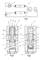
- FIG. 1 a schematic illustration of a hydraulic system comprising an inventive slide valve
- FIG. 2 a schematic illustration, in longitudinal portion, of the slide valve in accordance with FIG. 1 , in open position;
- FIG. 3 the slide valve in accordance with FIG. 2 , in closed position
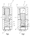
- FIG. 4 a schematic illustration, in longitudinal section, of a modified embodiment of a slide valve, in open position
- FIG. 5 the slide valve in accordance with FIG. 4 , in closed position.
- FIG. 1 shows a hydraulic system 1 , which includes a hydraulic pump and a user or a load 3 , for example, in the form of a hydraulic cylinder.
- Hydraulic system 1 may be a power-assisted steering system of a motor vehicle or an otherwise comparable system.
- hydraulic system 1 comprises, for example, two dampers 4 , 5 , which, for example, are designed as resonator dampers.
- dampers 4 , 5 are arranged parallel and connected with a main valve block 6 .
- Said valve block comprises an inlet communicating with the two dampers 4 , 5 , an outlet leading to load 3 and another outlet leading to a return line 7 .
- the latter is connected with the suction connection of hydraulic pump 2 .
- Its pressure-side connection branches into damper 5 , on the one hand, and into a slide valve 8 , on the other hand, said slide valve being upstream of damper 4 .
- Slide valve 8 is switched to open passage at relatively low pressures and blocks passage when a set pressure limit is exceeded.
- dampers 4 , 5 can be the same or can be different from each other. When connected parallel, their combined flow resistance is lower. In particular, damper 4 may display a particularly low flow resistance.
- main valve block 6 switches the outlets of dampers 4 , 5 more or less to load 3 , the pressure between load 3 and the outlet of hydraulic pump 2 increases.
- damper 4 If, in so doing, said pressure exceeds a limit, the slide valve performs its blocking function, thus rendering damper 4 inactive.
- damper 5 which may exhibit a higher flow resistance and is designed to possibly completely dampen pulsations occurring under load.
- the now occurring flow resistance plays a subordinate part in view of energy losses in the hydraulic system 1 , because this resistance occurs only temporarily.
- FIGS. 2 and 3 show the design of slide valve 8 and will now be referred to.
- Slide valve 8 has a valve housing 9 through which extends a passage channel 11 Said channel is designed, for example, as a straight cylindrical bore provided on each of its two opening with an internal thread 12 , 13 in order to permit the connection of lines.
- a slide bore 14 In a direction transverse to passage channel 11 is a slide bore 14 which intersects passage channel 11 centrally and at right angles.
- the diameter of slide bore 14 is at least as large as or larger than that of passage channel 11 . If the diameter of slide bore 14 is smaller than that of passage channel 11 , complete closure is not achieved when slide valve 8 performs its blocking function, but only a strong reduction of the passing flow is achieved. This, too, may be desirable.
- Slide bore 14 has a first section 15 , depicted below passage channel 11 in FIGS. 2 and 3 , and a second section 16 , depicted above passage channel 11 in FIGS. 2 and 3 .
- the preferably cylindrical slide bore 14 is preferably configured as a pocket bore and hence closed on one end. On its open end, said pocket bore is closed, for example, by an adjusting screw or screw plug 17 .
- Slide bore 14 accommodates a slide 18 , which is essentially rotation-symmetrical and supported such that it can be moved in a direction transverse to the passage channel.
- Slide 18 has a flat cylindrical and hence disk-like head 19 seated in section 15 of slide bore 14 .
- the outside diameter of head 19 is slightly smaller than the diameter of slide bore 14 . In so doing, said head is seated in a sealing yet sliding manner in said slide bore.
- head 19 On its side facing passage channel 11 , head 19 has a flat annular surface or, as indicated in FIGS. 2 and 3 , a saddle-shaped surface 21 .
- Said surface may be configured in such a manner that it, as illustrated by the position of slide 18 in FIG. 2 , rests snugly against the cylindrical wall of the passage channel in order to cause minimal disruption to the flow at this point and thus to produce low flow resistance.
- a pin portion 22 projects centrally from head 19 , said pin portion preferably being connected in one piece with head 19 .
- Pin portion 22 has a diameter which is substantially smaller than that of head 19 . Said pin portion's diameter is selected such that it impairs the clear flow cross-section of passage channel 11 as little as possible.
- the length of pin portion 22 corresponds preferably to the diameter of passage channel 11 .
- pin portion 22 On its end away from head 19 , pin portion 22 has, preferably molded in one piece to said pin portion 22 , a blocking portion 23 that is essentially configured as a cylindrical plunger and is seated in section 16 of the overall cylindrical bore 14 so as to be movable with minimal play in axial direction. Said blocking portion's length is greater than the diameter of passage channel 11 and thus also longer than pin portion 22 .
- blocking portion 23 On its side facing passage channel 11 , blocking portion 23 has a flat annular surface or, as depicted in FIGS. 2 and 3 , a saddle-shaped annular surface 24 , which encloses pin portion 22 and which follows the cylindrical contour of the wall of passage channel 11 . Consequently, annular surface 24 adjoins the wall of passage channel 11 in a smooth and stepless manner when slide 18 is in the position shown in FIG. 2 .
- Two or more channels 25 , 26 traverse head 19 in longitudinal direction. Thus, these channels lead out of passage channel 11 into a chamber 27 which is divided by blocking portion 23 into section 16 of slide bore 14 .
- Blocking portion 23 comprises a flat end surface, creating a boundary for the chamber.
- head 19 divides a chamber 28 , in which a compression spring 29 is arranged. This compression spring abuts with its one end against the abutting surface of head 19 and with its other end against adjusting screw or screw plug 17 .
- Chamber 28 may be vented toward the outside, for example, by a not specifically illustrated central bore of the adjusting screw or screw plug, or by another channel.
- Head 19 is preferably supported sealed in slide bore 14 . To do so, said head has on its outer cylindrical generated surface a ring groove to accommodate a gasket element, for example an O-ring 20 . Instead of a sealing element, lip seals or other sealing elements may be provided.
- a back-up ring may be provided, said back-up ring not being shown.
- chamber 28 is connected with an oil discharge line leading to the suction connection of hydraulic pump 2 .
- the slide valve 8 that has been described so far operates as follows:
- a damping gap 32 having reached a value of zero at the point illustrated in FIG. 3 is created between the outside circumference of blocking portion 23 and the internal wall of section 15 of slide bore 14 .
- This point is determined by a virtual plane, which includes the axis of passage channel 11 , as well as the axis of slide bore 14 .
- This plane marks a line on the wall of passage channel 11 , as well as on the convex surface of blocking section 23 . The meeting point of these lines is exactly that point at which the damping gap reaches the value of zero. This position is automatically controlled by slide 18 as long as the pressure in passage channel 11 exceeds the switch-off value.
- FIGS. 4 and 5 show a modified embodiment of inventive slide valve 8 .
- inventive slide valve 8 uses the same reference numbers as the above-described figures, the description and the design, as well as the function, apply correspondingly.
- Chamber 28 is provided with a depressurizing bore 33 , which, when the bearing of head 19 is sealed, is open toward the outside and otherwise leads to an oil-collecting line.
- head 19 may be sealed relative to slide bore 14 by means of a sealing element, for example, an O-ring. However, said head may be seated in slide bore 14 , even with a slight leak, when decompression bore 33 is connected to an oil-collecting line.
- blocking portion 23 does not have channels 25 , 26 . They are replaced by a bypass channel 34 leading from passage channel 11 into chamber 27 .
- the surfaces (surface 21 and annular surface 24 ) coming into contract with the flow are in parallel alignment with the flow, and thus in parallel alignment with the wall of passage channel 11 , in such a manner that the just occurring flow through passage channel 11 does not apply a combined force on these surfaces.
- surface 21 is arranged symmetrically to annular surface 24 and relative to a central plane which intersects pin portion 22 at right angles.
- pin portion 22 has also a cylindrical shape.
- Bypass channel 34 like channels 25 , 26 , branches off passage channel 11 in transverse direction and thus transmits the static pressure acting on the wall to chamber 27 .
- the inventive slide valve 8 comprises a slide 18 which is supported such that it can be moved in a direction transverse to passage channel 11 . It has an asymmetrical configuration such that pressure prevailing in passage channel 11 can be transmitted through suitable channels 25 , 26 , 34 to one side of slide 18 , while the other side is not subjected to pressure or to a constant low pressure.
- a spring 29 holding slide 18 in open position counteracts said pressure. If the fluid pressure prevails, slide 18 is moved into blocking position where it remains until the pressure again drops below the switching limit.
Landscapes
- Engineering & Computer Science (AREA)
- General Engineering & Computer Science (AREA)
- Physics & Mathematics (AREA)
- Mechanical Engineering (AREA)
- Fluid Mechanics (AREA)
- General Physics & Mathematics (AREA)
- Automation & Control Theory (AREA)
- Safety Valves (AREA)
- Check Valves (AREA)
- Fluid-Driven Valves (AREA)
- Valve Device For Special Equipments (AREA)
- Fluid-Pressure Circuits (AREA)
Abstract
The inventive sliding valve (8) comprises a slide (18), which is mounted in a manner that enables it to move transversal to the passage channel (11). This valve is provided with an asymmetrical design whereby enabling the pressure prevailing in the passage channel (11) to reach a side of the slide (18) via suitable ducts (25, 26), whereas the other side is not subjected to any pressure or only to a constant low pressure. A pressure spring (29) works counter to the pressure and holds the slide (18) in the open position. In the event the fluid pressure prevails, the slide (18) is displaced into the blocking position in which it remains until the pressure falls below the switching limit once again.
Description
The invention relates to a slide valve for hydraulic systems, as well as to such a hydraulic system.
In hydraulic systems, it is frequently important to switch pressure-dependent or flow-dependent branches to be either connected or disconnected.
This is necessary, for example, in order to be able to enable various damping measures that are a function of various operating states.
For example, document DE 196 42 837 C1 discloses a hydraulic power-assisted steering system which is set up to provide the driver with a good feel of the road, i.e., on the one hand, to provide feedback on forces that act on the wheels and that can be felt in the steering wheel and, on the other hand, to prevent rough shocks caused by bumpy roads from reaching the steering wheel. To achieve this, the tie rod is provided with a hydraulic cylinder having two working chambers that, during straight-line driving, are connected with each by means of a control valve block and a short-circuiting line. This short-circuiting line contains two damper valves which are switched in series with respect to the short-circuiting action. These damper valves contain a disk-shaped valve-closing member that is arranged on an axially slidable pin and is immersed in oil. If the rate of flow exceeds a certain limit, this flow carries along the valve-closing member, forcing it against its associated valve seat. A pressure difference acting on the valve seat's support pin has the same effect. If the valve closure sits snugly on its valve seat, only relatively narrow throttle channels are still free, so that the fluid flow can be substantially reduced.
This valve responds to pressure differences, as well as to high flow rates. However, there are situations in which the valve is to switch only as a function of pressure, however not as a function of increasing flow. In addition, such valves are frequently expected to work without exhibiting any hysteresis or low hysteresis and display a well-defined response threshold in the long run.
Referring to this, it is the object of the invention to provide a simple and durable valve which switches as a function of pressure.
This object is achieved with a slide valve as in Claim 1. The inventive slide valve comprises a valve housing with a passage channel. In a direction transverse to said passage channel, a slide bore is provided in which a slide is seated.
Said slide has a head acting as the drive for the slide. Said head's corresponding effective area is aligned parallel to the flow passing through the passage channel. Referring to its opposite end, the slide has a blocking portion, so that the passage channel passes between two preferably essentially equally dimensioned and, e.g., annular surfaces of the slide. Both surfaces are aligned parallel to each other, so that a flow through the passage channel cannot generate a pressure difference and thus no resultant force that can act on the slide in closing direction. Consequently, the slide cannot be closed by the flow through the passage channel.
The head and the blocking portion divide one chamber, respectively, in the slide bore. While the chamber divided by the head preferably is not subjected to pressure, the chamber divided by the blocking portion preferably communicates with the fluid pressure of the passage channel. Consequently, the pressurized surfaces aligned in the slide's two opposite directions of movement have an overall different size, thus applying a force to the slide when the passage channel is pressurized. As a result, a strictly pressure-dependent slide valve is obtained. The chamber, divided by the blocking portion, communicates with the passage channel preferably via a channel branching off the passage channel at right angles. As a result of this, the chamber, divided by the blocking portion, is subjected to reduced static pressure as the flow through the passage channel increases, thus causing a force acting in opening direction of the slide. Only when this force or the spring force has exceeded the pressure prevailing in the passage channel, will the slide start to move in closing direction. As the flow decreases, the suction effect decreases, said suction effect having slightly reduced the pressure in the chamber, divided by the blocking portion, and having thus created a force acting in opening direction. As this force is ceasing, the slide valve closes more rapidly. In all, a switch-like closing of the slide valve is achieved.
The slide valve may be used, for example, in a hydraulic system in order to activate or deactivate various pressure-dependent dampers. These dampers preferably are resonators that are adjusted for various load-dependent and hence pressure-dependent pulsations.
Preferably, the chamber, divided by the head in the slide bore, may be provided with an outside vent. If an oil-tight bearing of the plunger in the slide bore is to be omitted, however, said chamber may be connected with an oil-collecting line via a relief line, which said oil-collecting line, for example, may be connected to the suction side of a hydraulic pump. In this way, special sealing measures may be omitted and the slide may be seated in its bearing in a particularly smooth-running manner. This is particularly advantageous when the valve is supposed to respond particularly rapidly, or when the valve is supposed to respond to very low pressures.
Preferably, the slide bore has a diameter that is greater than that of the passage channel. As a result of this, the slide is able to completely block the passage channel.
As a result, an open/shut-valve is obtained. If only a reduction of the passage channel is desired, the slide portion may be provided with a peripheral groove or the diameter of the slide channel may be selected smaller than the diameter of the passage channel.
In order to bias the slide resiliently toward the open position of the valve, preferably a spring is provided which is arranged in the chamber that is divided by the head, said chamber being vented or provided with an oil discharge line.
This spring is configured as a compression spring pushing with its one end against the head and with its other end against an abutment, said abutment consisting, for example, of a screw used for closing the respective chamber. In an improved embodiment, this screw may be used as a setting screw in order to be able to affect the release pressure of the slide valve.
The spring is preferably pre-tensioned such that it will not respond for a long time if pressure increases gradually in order to then achieve a sudden movement of the slide in blocking direction.
The blocking portion preferably has a diameter which is slightly smaller than that of the section of the slide bore receiving the head, so that the slide bore having the blocking section defines the damping gap. This minimizes time delays when the valve is closed in the event of a pressure drop, i.e., when a drop below the switching pressure occurs. Optionally, the damping gap communicates with the working chamber, divided by the blocking portion via the channel leading through the blocking portion, in order to thus decompress said working chamber in the event the pressure in the passage channel drops. However, it is not absolutely necessary for the channel to extend through the blocking portion. The channel may also be provided in the valve housing.
The deactivation time of the valve is then not dependent on the size of the damping gap.
The inventive slide valve may be provided in a hydraulic system between a hydraulic pump and a load or, more precisely, between a hydraulic pump and a main valve block upstream of the load, said valve block activating and deactivating resonators. Preferably, the resonators are arranged between the pump and the load or between the pump and the main valve block, and are used to dampen pressure pulsations. Pulsations occur, for example, with the application of greater loads when the pump is connected partially or completely with the load via the main valve block. In this case, the slide valve may achieve a rapid switching of the damping resonators. This may occur independent of the material flow transported by the pump, said flow not being a function of the main valve block but, at most, of the pump rate.
Additional details of advantageous inventive embodiments result from the drawings, the description or the subclaims.
The drawings show examples of the invention. They show in
Hydraulic system 1 may be a power-assisted steering system of a motor vehicle or an otherwise comparable system.
In addition, hydraulic system 1 comprises, for example, two dampers 4, 5, which, for example, are designed as resonator dampers. On their output side, dampers 4, 5 are arranged parallel and connected with a main valve block 6. Said valve block comprises an inlet communicating with the two dampers 4, 5, an outlet leading to load 3 and another outlet leading to a return line 7. The latter is connected with the suction connection of hydraulic pump 2. Its pressure-side connection branches into damper 5, on the one hand, and into a slide valve 8, on the other hand, said slide valve being upstream of damper 4. Slide valve 8 is switched to open passage at relatively low pressures and blocks passage when a set pressure limit is exceeded. If the main valve block 6 connects the outlets of dampers 4, 5 directly with return line 7 and thus with the suction connection of hydraulic pump 2, slide valve 8 is set to open passage, so that both dampers 4, 5 are switched parallel. Referring to their flow resistance, dampers 4, 5 can be the same or can be different from each other. When connected parallel, their combined flow resistance is lower. In particular, damper 4 may display a particularly low flow resistance.
If main valve block 6 switches the outlets of dampers 4, 5 more or less to load 3, the pressure between load 3 and the outlet of hydraulic pump 2 increases.
If, in so doing, said pressure exceeds a limit, the slide valve performs its blocking function, thus rendering damper 4 inactive. The entire fluid stream demanded by hydraulic pump 2 now must pass through damper 5 which may exhibit a higher flow resistance and is designed to possibly completely dampen pulsations occurring under load. The now occurring flow resistance plays a subordinate part in view of energy losses in the hydraulic system 1, because this resistance occurs only temporarily.
Slide bore 14 has a first section 15, depicted below passage channel 11 in FIGS. 2 and 3 , and a second section 16, depicted above passage channel 11 in FIGS. 2 and 3 . The preferably cylindrical slide bore 14, in turn, is preferably configured as a pocket bore and hence closed on one end. On its open end, said pocket bore is closed, for example, by an adjusting screw or screw plug 17.
Slide bore 14 accommodates a slide 18, which is essentially rotation-symmetrical and supported such that it can be moved in a direction transverse to the passage channel. Slide 18 has a flat cylindrical and hence disk-like head 19 seated in section 15 of slide bore 14. The outside diameter of head 19 is slightly smaller than the diameter of slide bore 14. In so doing, said head is seated in a sealing yet sliding manner in said slide bore. On its side facing passage channel 11, head 19 has a flat annular surface or, as indicated in FIGS. 2 and 3 , a saddle-shaped surface 21. Said surface may be configured in such a manner that it, as illustrated by the position of slide 18 in FIG. 2 , rests snugly against the cylindrical wall of the passage channel in order to cause minimal disruption to the flow at this point and thus to produce low flow resistance.
A pin portion 22 projects centrally from head 19, said pin portion preferably being connected in one piece with head 19.
Two or more channels 25, 26 traverse head 19 in longitudinal direction. Thus, these channels lead out of passage channel 11 into a chamber 27 which is divided by blocking portion 23 into section 16 of slide bore 14. Blocking portion 23 comprises a flat end surface, creating a boundary for the chamber.
In section 15 of slide bore 14, head 19 divides a chamber 28, in which a compression spring 29 is arranged. This compression spring abuts with its one end against the abutting surface of head 19 and with its other end against adjusting screw or screw plug 17. Chamber 28 may be vented toward the outside, for example, by a not specifically illustrated central bore of the adjusting screw or screw plug, or by another channel. Head 19 is preferably supported sealed in slide bore 14. To do so, said head has on its outer cylindrical generated surface a ring groove to accommodate a gasket element, for example an O-ring 20. Instead of a sealing element, lip seals or other sealing elements may be provided. In order to support the O-ring or another sealing element, a back-up ring may be provided, said back-up ring not being shown. However, if head 19 is not sealed fluid-tight with respect to the wall of slide bore 14, chamber 28 is connected with an oil discharge line leading to the suction connection of hydraulic pump 2.
The slide valve 8 that has been described so far operates as follows:
If fluid is present in passage channel 11 at low pressure, slide 18 is in the position depicted in FIG. 2 . Pressure spring 29 holds the slide in its upper position, said position being a passage position. The hydraulic fluid fills passage channel 11, as well as channels 25, 26 and chamber 27. However, due to the sealed seat of head 19, said fluid cannot enter into chamber 28. A force generated by the fluid pressure, said fluid pressure being calculated based on the fluid pressure and the circular surface described by head 19, is applied against the force of pressure spring 29. This is because the fluid pressure acts counter to the force of pressure spring 29 to the extent that said fluid pressure acts on surface 21, as well as on a portion of the upper abutting surface of blocking portion 23. The outer annular zone of the latter is counterbalanced by annular surface 24, whereas a surface area corresponding to the area of the cross-section of pin portion 22 remains without counter-balance and thus contributes to the force in opening direction.
If the flow, i.e., the flow rate in passage channel 11, increases, a reduced pressure acts on surface 21 as well as on annular surface 24. Via channels 25, 26, this reduced pressure has also a pressure-reducing effect in chamber 27, so that slide 18 is held even more securely in open position. Consequently, an increased flow cannot result in the sudden and undesired closing of slide valve 8.
However, if the static pressure in passage channel 11 increases beyond a pressure limit used as switching limit, the slide moves into the position as in FIG. 3 . This is achieved when the pressure acting on the cross-section of head 19 generates a force that exceeds the force of compression spring 29. This latter force is applied until the lower edge of blocking portion 23 has reached the lower limit of passage channel 11. In so doing, blocking portion 23, as illustrated by FIG. 3 , can completely separate an annular chamber 21 enclosing pin 22 from passage channel 11. If this is the case, the fluid received by chamber 27 and by chamber 31, as well as by channels 25, 26, is essentially depressurized. In this state, compression spring 29 is no longer opposed by any force. Consequently, slide 18 retracts until chamber 31 is just barely closed by passage channel 11. A damping gap 32 having reached a value of zero at the point illustrated in FIG. 3 is created between the outside circumference of blocking portion 23 and the internal wall of section 15 of slide bore 14. This point is determined by a virtual plane, which includes the axis of passage channel 11, as well as the axis of slide bore 14. This plane marks a line on the wall of passage channel 11, as well as on the convex surface of blocking section 23. The meeting point of these lines is exactly that point at which the damping gap reaches the value of zero. This position is automatically controlled by slide 18 as long as the pressure in passage channel 11 exceeds the switch-off value. As long as this is the case, this pressure is also transmitted to chamber 31 via the damping gap 32 that has been adjusted to zero by this pressure. If, however, the pressure drops below this switching pressure, chamber 31 and, with it chamber 27, are also depressurized via damping gap 32, as a result of which compression spring 29 returns slide 18 back into its home position of FIG. 2 without any disruptive time delay. Now, passage channel 11 has again been cleared.
The differences are explained as follows:
Furthermore, blocking portion 23 does not have channels 25, 26. They are replaced by a bypass channel 34 leading from passage channel 11 into chamber 27.
As in the above-described embodiment, the surfaces (surface 21 and annular surface 24) coming into contract with the flow are in parallel alignment with the flow, and thus in parallel alignment with the wall of passage channel 11, in such a manner that the just occurring flow through passage channel 11 does not apply a combined force on these surfaces. In so doing, surface 21 is arranged symmetrically to annular surface 24 and relative to a central plane which intersects pin portion 22 at right angles. Thus, any force generated on the surface as a result of the flow is consequently relieved by an equal force directed in opposite direction, said latter force being generated on annular surface 24.
This applies in the same manner to the above-described embodiment. Considering this, pin portion 22 has also a cylindrical shape.
In view of the function, there is a difference such that chamber 27 in blocked state of slide valve 8 (FIG. 5 ) is not subjected to the static pressure via damping gap 32 but us subjected to such pressure directly via bypass channel 34. Therefore, blocking portion 23 can be moved unimpaired in blocking direction until head 19 locates an abutment. Said abutment may, for example, be provided on adjusting screw or screw plug 17. Likewise, the depressurization of chamber 27 takes place via bypass channel 34.
As in the above-described example, in open position, a certain suction acts on chamber 27 via bypass channel 34 if the flow rate through passage channel 11 is high. However, as the blocking operation begins, this suction decreases, thus eliminating the force that has held slide 18 in open position up to that time and has supported compression spring 29. This elimination of force leads to a suddenly activating closure of slide valve 8. In the same way, the flow through passage channel 11 accelerates the opening operation when said channel is opened. Therefore, the slide valve closes rapidly and precisely. Intermediate positions which could cause vibration or noise phenomena are avoided.
The inventive slide valve 8 comprises a slide 18 which is supported such that it can be moved in a direction transverse to passage channel 11. It has an asymmetrical configuration such that pressure prevailing in passage channel 11 can be transmitted through suitable channels 25, 26, 34 to one side of slide 18, while the other side is not subjected to pressure or to a constant low pressure. A spring 29 holding slide 18 in open position counteracts said pressure. If the fluid pressure prevails, slide 18 is moved into blocking position where it remains until the pressure again drops below the switching limit.
Claims (19)
1. A hydraulic system including a hydraulic pump, a load, an actuator for moving the load, a control valve fluidly connected to the actuator, at least two branches parallel to each other and fluidly connected between the hydraulic pump and the control valve with each branch including at least one damper, and at least one slide valve arranged in one of the branches, the slide valve comprising:
a valve housing having a passage channel with a slide bore extending in a direction transverse to the passage channel; and
a slide supported within and longitudinally movable relative to the slide bore between an open position and a blocking position, the slide having a head, a blocking portion defining a blocking position when the blocking portion is aligned with the passage channel, and a pin portion connecting the head to the blocking portion and defining an open position when the pin portion is aligned with the passage channel, wherein the blocking portion divides the slide bore into a chamber,
wherein at least one channel is provided that permits fluid communication between the chamber and the passage channel, thereby allowing the chamber to be subjected to the fluid pressure prevailing in the passage channel,
wherein, when the pressure in the passage channel exceeds a predetermined fluid pressure, the slide moves to its blocking position.
2. The hydraulic system of claim 1 , wherein the head is supported in a sealed manner in the slide bore.
3. The hydraulic system of claim 1 , wherein the head divides the slide bore into a vented chamber.
4. The hydraulic system of claim 1 , further including a compression spring to pre-tension the slide, the spring including a first end abutting the head and a second end abutting an abutment.
5. The hydraulic system of claim 4 , wherein the abutment is adjustable.
6. The hydraulic system of claim 4 , wherein the compression spring is arranged in the chamber.
7. The hydraulic system of claim 1 , wherein the blocking portion is connected to the head by a pin portion having a diameter that is smaller than a diameter of the blocking portion.
8. The hydraulic system of claim 1 , wherein the blocking portion has a diameter which is slightly smaller than a diameter of a section of the slide bore accommodating the head, such that the slide bore defines a damping gap with the blocking portion when the blocking portion is moved toward the blocking position.
9. The hydraulic system of claim 1 , wherein the diameter of the slide bore is at least as large as the diameter of the passage channel.
10. The hydraulic system of claim 1 , further comprising a compression spring for providing a spring force that urges the slide toward the open position against the fluid pressure in the passage channel, wherein the spring force is sized such that:
when the fluid pressure prevailing within the passage channel is less than the predetermined fluid pressure, the slide remains in its open position, and
when the fluid pressure prevailing within the passage channel is greater than the predetermined fluid pressure, the slide moves to its blocking position.
11. The hydraulic system of claim 1 , wherein the at least one channel is provided in the blocking portion of the slide.
12. The hydraulic system of claim 1 , wherein the at least one channel includes a bypass channel provided in the valve housing upstream from the slide.
13. A hydraulic system comprising:
a hydraulic pump,
an actuator for moving a load;
a control valve fluidly connected to the actuator;
at least two branches fluidly connected between the pump and the control valve, each branch including at least one damper; and
a pressure sensitive, shut-off valve provided in one of the branches, the shut-off valve including:
a valve housing having a passage channel with a slide bore extending in a direction traverse to the passage channel, and
a slide supported in the slide bore so as to be moveable in the traverse direction within the slide bore between an open position permitting flow through the passage channel and a closing position preventing flow through the passage channel,
wherein the slide is configured to switch from its open position to its closed position when the pressure in the passage channel exceeds a predetermined pressure limit.
14. The hydraulic system of claim 13 , wherein the shut-off valve is provided between the pump and the damper.
15. The hydraulic system of claim 13 , wherein the slide includes a head, a blocking portion that defines the blocking position, and a pin portion that connects the head to the blocking portion and defines the open position.
16. The hydraulic system of claim 15 , wherein the blocking portion divides the slide bore into a chamber, wherein at least one channel is provided that permits fluid communication between the chamber and the passage channel, thereby allowing the chamber to be subjected to the fluid pressure prevailing in the passage channel,
wherein, when the pressure in the passage channel exceeds a predetermined pressure limit, the slide moves from its open position to its blocking position.
17. The hydraulic system of claim 16 , wherein the at least one channel is provided in the blocking portion of the slide.
18. The hydraulic system of claim 16 , wherein the at least one channel includes a bypass channel provided in the valve housing.
19. The hydraulic system of claim 13 , further comprising a compression spring for providing a spring force that urges the slide toward the open position against the fluid pressure in the passage channel, wherein the spring force is sized such that:
when the pressure prevailing within the passage channel is less than the predetermined pressure limit, the slide remains in its open position, and
when the pressure prevailing within the passage channel is greater than the predetermined pressure limit, the slide moves from its open position to its blocking position.
Applications Claiming Priority (3)
| Application Number | Priority Date | Filing Date | Title |
|---|---|---|---|
| DE10325202.9 | 2003-06-04 | ||
| DE2003125202 DE10325202A1 (en) | 2003-06-04 | 2003-06-04 | Pressure-dependent shut-off valve and hydraulic system with such |
| PCT/EP2004/005712 WO2004109166A1 (en) | 2003-06-04 | 2004-05-27 | Pressure-dependent check valve and hydraulic system equipped therewith |
Publications (2)
| Publication Number | Publication Date |
|---|---|
| US20070056633A1 US20070056633A1 (en) | 2007-03-15 |
| US7617841B2 true US7617841B2 (en) | 2009-11-17 |
Family
ID=33494819
Family Applications (1)
| Application Number | Title | Priority Date | Filing Date |
|---|---|---|---|
| US10/559,549 Expired - Fee Related US7617841B2 (en) | 2003-06-04 | 2004-05-27 | Pressure-dependent check valve and hydraulic system equipped therewith |
Country Status (10)
| Country | Link |
|---|---|
| US (1) | US7617841B2 (en) |
| EP (1) | EP1629225B1 (en) |
| JP (1) | JP2006526743A (en) |
| CN (1) | CN1330900C (en) |
| AT (1) | ATE491905T1 (en) |
| BR (1) | BRPI0411399A (en) |
| DE (2) | DE10325202A1 (en) |
| MX (1) | MXPA05013023A (en) |
| WO (1) | WO2004109166A1 (en) |
| ZA (1) | ZA200600024B (en) |
Cited By (11)
| Publication number | Priority date | Publication date | Assignee | Title |
|---|---|---|---|---|
| US20120196236A1 (en) * | 2010-12-09 | 2012-08-02 | David Deng | Heating system with pressure regulator |
| US9423123B2 (en) | 2013-03-02 | 2016-08-23 | David Deng | Safety pressure switch |
| US9541210B2 (en) * | 2012-10-23 | 2017-01-10 | Fluor Technologies Corporation | Pipeline pressure isolation systems and devices |
| US9739389B2 (en) | 2011-04-08 | 2017-08-22 | David Deng | Heating system |
| US9752782B2 (en) | 2011-10-20 | 2017-09-05 | David Deng | Dual fuel heater with selector valve |
| US9752779B2 (en) | 2013-03-02 | 2017-09-05 | David Deng | Heating assembly |
| US10073071B2 (en) | 2010-06-07 | 2018-09-11 | David Deng | Heating system |
| US10174853B2 (en) | 2016-10-13 | 2019-01-08 | Itt Manufacturing Enterprises Llc | Compressed natural gas (CNG) pressure regulator |
| US10222057B2 (en) | 2011-04-08 | 2019-03-05 | David Deng | Dual fuel heater with selector valve |
| US10240789B2 (en) | 2014-05-16 | 2019-03-26 | David Deng | Dual fuel heating assembly with reset switch |
| US10429074B2 (en) | 2014-05-16 | 2019-10-01 | David Deng | Dual fuel heating assembly with selector switch |
Families Citing this family (23)
| Publication number | Priority date | Publication date | Assignee | Title |
|---|---|---|---|---|
| JP4559824B2 (en) * | 2004-11-08 | 2010-10-13 | 株式会社豊田自動織機 | Hydraulic circuit |
| DE102006021709A1 (en) | 2006-05-10 | 2007-11-15 | Eaton Fluid Power Gmbh | Connection device with pressure valve |
| NZ551311A (en) * | 2006-11-15 | 2009-06-26 | William Steven Gillanders | A hydraulic valve and a double acting hydraulic actuator |
| DE102009054583B4 (en) * | 2009-12-14 | 2017-12-28 | Hansgrohe Se | Connection valve and hose shower arrangement |
| US20120129128A1 (en) * | 2010-11-18 | 2012-05-24 | Ramvac Dental Products, Inc. | Vacuum Level Control Valve For A Dental Vacuum System |
| MX363439B (en) * | 2013-03-15 | 2019-03-22 | Scott Tech Inc | Systems for filling a gas cylinder. |
| CN103836220A (en) * | 2014-02-18 | 2014-06-04 | 潘健 | Self-sealing slide valve |
| CN106438371B (en) * | 2016-11-25 | 2019-06-07 | 苏州强时压缩机有限公司 | Air compressor, bypass auxiliary feed-oil method and by-passing valve |
| WO2019114903A1 (en) * | 2017-12-13 | 2019-06-20 | Hans Jensen Lubricators A/S | Large slow-running two-stroke engine and method of lubricating such engine, as well as an injector for such engine and method and a valve system and use thereof |
| DE102018210277B4 (en) | 2018-06-25 | 2021-03-18 | Geze Gmbh | Valve |
| DE102018210278B4 (en) | 2018-06-25 | 2021-03-18 | Geze Gmbh | Hydraulic, damped drive for a door or window sash |
| DE102018210276B4 (en) * | 2018-06-25 | 2021-03-18 | Geze Gmbh | Valve |
| FR3084922B1 (en) * | 2018-08-10 | 2020-11-20 | Bontaz Centre R & D | ON / OFF SOLENOID VALVE OFFERING 2 LEVELS OF MECHANICAL PRESSURE REGULATION |
| JP7336836B2 (en) * | 2018-09-10 | 2023-09-01 | ナブテスコ株式会社 | Flow control valve and working machine |
| JP6938828B2 (en) * | 2018-12-28 | 2021-09-22 | Smc株式会社 | Low noise gate valve |
| CN110617342A (en) * | 2019-10-16 | 2019-12-27 | 湖南机油泵股份有限公司 | Pressure regulating valve capable of reducing pressure fluctuation |
| CN111237275B (en) * | 2020-01-10 | 2024-05-17 | 武汉科技大学 | High-pressure slide valve type one-way valve |
| CN113565821A (en) * | 2021-06-30 | 2021-10-29 | 郑州磨料磨具磨削研究所有限公司 | Hydraulic stop valve capable of adjusting closing pressure and hydraulic system |
| CN114412885B (en) * | 2022-01-20 | 2022-12-27 | 中山大学·深圳 | Method and device for improving mechanical flexibility of hydraulic valve control cylinder system |
| CN116624702B (en) * | 2023-04-17 | 2025-12-02 | 浙江瑞霖建设有限公司 | A Building Electromechanical Installation Structure and Installation Method Based on BIM Technology |
| CN117404252B (en) * | 2023-11-15 | 2026-02-24 | 广西龙源风力发电有限公司 | Wind turbine generator system mounting platform |
| CN118582652B (en) * | 2024-07-19 | 2025-10-14 | 广东省洛仑兹技术股份有限公司 | Hydrogen storage container and hydrogen-powered vehicle |
| CN121345836B (en) * | 2025-12-18 | 2026-03-10 | 芜湖伊顿流体科技有限公司 | Servo pump control hydraulic power device with energy recovery function and control method thereof |
Citations (10)
| Publication number | Priority date | Publication date | Assignee | Title |
|---|---|---|---|---|
| US378291A (en) * | 1888-02-21 | Teekitoliy | ||
| GB102688A (en) | 1916-05-30 | 1916-12-21 | Francis Thomas Jenkins | Improvements in Valves for Reducing the Pressure of Steam, Air, or other Gases. |
| US2701704A (en) * | 1951-10-26 | 1955-02-08 | Theodore G Lawrence | Automatic cutoff valve |
| US3472278A (en) | 1966-10-27 | 1969-10-14 | Henriksen & Henriksen I S | Slide valve for opening and closing at least one passage for a flowing medium and an apparatus comprising at least one such slide valve |
| US3971404A (en) * | 1974-06-17 | 1976-07-27 | Graco Inc. | Hydraulic runaway control valve |
| FR2397578A1 (en) | 1977-07-13 | 1979-02-09 | Baudet Alain | Safety valve for hydraulic equipment - opens by=pass line under excessive pressure and is closed by sudden pressure drop |
| US4874011A (en) * | 1989-01-12 | 1989-10-17 | Canzano Pasquale S | Gas pressure regulator for controlling low pressure |
| DE19642837C1 (en) | 1996-10-17 | 1998-01-29 | Daimler Benz Ag | Motor vehicle suspension shock absorber valve |
| US20030019525A1 (en) * | 2001-07-24 | 2003-01-30 | Der-Fan Shen | Flow regulator for water pump |
| US20030019526A1 (en) * | 2001-07-24 | 2003-01-30 | Der-Fan Shen | Flow regulator for water pump |
Family Cites Families (4)
| Publication number | Priority date | Publication date | Assignee | Title |
|---|---|---|---|---|
| JPS5159181A (en) * | 1974-11-20 | 1976-05-24 | Hitachi Construction Machinery | YUATSUSHIKIKENSETSUKIKAI NIOKERU SOKOBUREEKYUATSUKAIRO |
| US4176984A (en) * | 1977-09-26 | 1979-12-04 | Fmc Corporation | Fish holding pan on traveling water screen and method of flushing same |
| DE3401369A1 (en) * | 1983-01-26 | 1984-08-02 | Beringer-Hydraulik GmbH, Neuheim, Zug | Pilot-controlled pressure-relief valve |
| FR2651341B1 (en) * | 1989-08-24 | 1993-12-24 | Barmag Ag | FLOW OR PRESSURE REGULATOR. |
-
2003
- 2003-06-04 DE DE2003125202 patent/DE10325202A1/en not_active Withdrawn
-
2004
- 2004-05-27 EP EP20040739389 patent/EP1629225B1/en not_active Expired - Lifetime
- 2004-05-27 MX MXPA05013023A patent/MXPA05013023A/en active IP Right Grant
- 2004-05-27 BR BRPI0411399 patent/BRPI0411399A/en not_active IP Right Cessation
- 2004-05-27 US US10/559,549 patent/US7617841B2/en not_active Expired - Fee Related
- 2004-05-27 WO PCT/EP2004/005712 patent/WO2004109166A1/en not_active Ceased
- 2004-05-27 JP JP2006508212A patent/JP2006526743A/en active Pending
- 2004-05-27 DE DE200450011999 patent/DE502004011999D1/en not_active Expired - Lifetime
- 2004-05-27 CN CNB200480015632XA patent/CN1330900C/en not_active Expired - Fee Related
- 2004-05-27 AT AT04739389T patent/ATE491905T1/en active
-
2006
- 2006-01-03 ZA ZA200600024A patent/ZA200600024B/en unknown
Patent Citations (10)
| Publication number | Priority date | Publication date | Assignee | Title |
|---|---|---|---|---|
| US378291A (en) * | 1888-02-21 | Teekitoliy | ||
| GB102688A (en) | 1916-05-30 | 1916-12-21 | Francis Thomas Jenkins | Improvements in Valves for Reducing the Pressure of Steam, Air, or other Gases. |
| US2701704A (en) * | 1951-10-26 | 1955-02-08 | Theodore G Lawrence | Automatic cutoff valve |
| US3472278A (en) | 1966-10-27 | 1969-10-14 | Henriksen & Henriksen I S | Slide valve for opening and closing at least one passage for a flowing medium and an apparatus comprising at least one such slide valve |
| US3971404A (en) * | 1974-06-17 | 1976-07-27 | Graco Inc. | Hydraulic runaway control valve |
| FR2397578A1 (en) | 1977-07-13 | 1979-02-09 | Baudet Alain | Safety valve for hydraulic equipment - opens by=pass line under excessive pressure and is closed by sudden pressure drop |
| US4874011A (en) * | 1989-01-12 | 1989-10-17 | Canzano Pasquale S | Gas pressure regulator for controlling low pressure |
| DE19642837C1 (en) | 1996-10-17 | 1998-01-29 | Daimler Benz Ag | Motor vehicle suspension shock absorber valve |
| US20030019525A1 (en) * | 2001-07-24 | 2003-01-30 | Der-Fan Shen | Flow regulator for water pump |
| US20030019526A1 (en) * | 2001-07-24 | 2003-01-30 | Der-Fan Shen | Flow regulator for water pump |
Cited By (13)
| Publication number | Priority date | Publication date | Assignee | Title |
|---|---|---|---|---|
| US10073071B2 (en) | 2010-06-07 | 2018-09-11 | David Deng | Heating system |
| US9222670B2 (en) * | 2010-12-09 | 2015-12-29 | David Deng | Heating system with pressure regulator |
| US20120196236A1 (en) * | 2010-12-09 | 2012-08-02 | David Deng | Heating system with pressure regulator |
| US10222057B2 (en) | 2011-04-08 | 2019-03-05 | David Deng | Dual fuel heater with selector valve |
| US9739389B2 (en) | 2011-04-08 | 2017-08-22 | David Deng | Heating system |
| US9752782B2 (en) | 2011-10-20 | 2017-09-05 | David Deng | Dual fuel heater with selector valve |
| US9541210B2 (en) * | 2012-10-23 | 2017-01-10 | Fluor Technologies Corporation | Pipeline pressure isolation systems and devices |
| US9752779B2 (en) | 2013-03-02 | 2017-09-05 | David Deng | Heating assembly |
| US9423123B2 (en) | 2013-03-02 | 2016-08-23 | David Deng | Safety pressure switch |
| US10240789B2 (en) | 2014-05-16 | 2019-03-26 | David Deng | Dual fuel heating assembly with reset switch |
| US10429074B2 (en) | 2014-05-16 | 2019-10-01 | David Deng | Dual fuel heating assembly with selector switch |
| US10174853B2 (en) | 2016-10-13 | 2019-01-08 | Itt Manufacturing Enterprises Llc | Compressed natural gas (CNG) pressure regulator |
| US10683945B2 (en) | 2016-10-13 | 2020-06-16 | Itt Manufacturing Enterprises Llc | Compressed natural gas (CNG) pressure regulator |
Also Published As
| Publication number | Publication date |
|---|---|
| CN1802528A (en) | 2006-07-12 |
| JP2006526743A (en) | 2006-11-24 |
| WO2004109166A1 (en) | 2004-12-16 |
| EP1629225B1 (en) | 2010-12-15 |
| CN1330900C (en) | 2007-08-08 |
| BRPI0411399A (en) | 2006-07-18 |
| US20070056633A1 (en) | 2007-03-15 |
| EP1629225A1 (en) | 2006-03-01 |
| ATE491905T1 (en) | 2011-01-15 |
| MXPA05013023A (en) | 2006-03-09 |
| DE10325202A1 (en) | 2005-01-20 |
| DE502004011999D1 (en) | 2011-01-27 |
| ZA200600024B (en) | 2007-01-31 |
Similar Documents
| Publication | Publication Date | Title |
|---|---|---|
| US7617841B2 (en) | Pressure-dependent check valve and hydraulic system equipped therewith | |
| US6986362B2 (en) | Pilot operated relief valve | |
| US7712724B2 (en) | Dynamic ball valve sealing device for three-way valves | |
| US4590968A (en) | Pilot valve operated pressure reducing valve | |
| EP1947363B1 (en) | Shock absorber | |
| EP1212545B1 (en) | Damper | |
| KR100367683B1 (en) | Damping force control type hydraulic shock absorber | |
| JPH01216106A (en) | Fluid safety brake valve gear | |
| KR20120079224A (en) | Direct-acting relief valve | |
| US5372157A (en) | Automatic bypass valve | |
| JP2000516885A (en) | Electro-hydraulic control device | |
| US20050155652A1 (en) | Pressure protection valve | |
| US7341434B2 (en) | Regulatory device comprising a threshold valve control valve | |
| US4194364A (en) | Arrangement for controlling the operation of a fluid-displacement machine | |
| US7234487B2 (en) | Cross-over relief valve assembly for use in bi-directional circuit | |
| EP3126200A1 (en) | Damping device and slip-controllable vehicle brake system | |
| US6871494B2 (en) | Hydraulic type brake apparatus | |
| WO2018144458A1 (en) | Reciprocating pump having a combination check valve and relief valve | |
| US3016018A (en) | Variable displacement pump | |
| CN102667273A (en) | Valve device | |
| JPH0351521Y2 (en) | ||
| JP2004084671A (en) | Device for controlling at least one gas exchange valve of an internal combustion engine | |
| RU2186262C1 (en) | Valve | |
| CA1225304A (en) | Hydraulic fuse valve assembly | |
| RU2302575C2 (en) | Two-stepped pressure valve |
Legal Events
| Date | Code | Title | Description |
|---|---|---|---|
| AS | Assignment |
Owner name: EATON FLUID POWER GMBH, GERMANY Free format text: ASSIGNMENT OF ASSIGNORS INTEREST;ASSIGNORS:ZIMPFER, MICHAEL;HILGERT, ANDREAS;REEL/FRAME:017566/0037 Effective date: 20060109 |
|
| REMI | Maintenance fee reminder mailed | ||
| LAPS | Lapse for failure to pay maintenance fees | ||
| STCH | Information on status: patent discontinuation |
Free format text: PATENT EXPIRED DUE TO NONPAYMENT OF MAINTENANCE FEES UNDER 37 CFR 1.362 |
|
| STCH | Information on status: patent discontinuation |
Free format text: PATENT EXPIRED DUE TO NONPAYMENT OF MAINTENANCE FEES UNDER 37 CFR 1.362 |
|
| FP | Lapsed due to failure to pay maintenance fee |
Effective date: 20131117 |