US7592958B2 - Multi-band antennas and radio apparatus incorporating the same - Google Patents
Multi-band antennas and radio apparatus incorporating the same Download PDFInfo
- Publication number
- US7592958B2 US7592958B2 US10/691,150 US69115003A US7592958B2 US 7592958 B2 US7592958 B2 US 7592958B2 US 69115003 A US69115003 A US 69115003A US 7592958 B2 US7592958 B2 US 7592958B2
- Authority
- US
- United States
- Prior art keywords
- ground plane
- monopole
- conductor loop
- rectangular
- antenna
- Prior art date
- Legal status (The legal status is an assumption and is not a legal conclusion. Google has not performed a legal analysis and makes no representation as to the accuracy of the status listed.)
- Expired - Fee Related, expires
Links
Images


Classifications
-
- H—ELECTRICITY
- H01—ELECTRIC ELEMENTS
- H01Q—ANTENNAS, i.e. RADIO AERIALS
- H01Q7/00—Loop antennas with a substantially uniform current distribution around the loop and having a directional radiation pattern in a plane perpendicular to the plane of the loop
-
- H—ELECTRICITY
- H01—ELECTRIC ELEMENTS
- H01Q—ANTENNAS, i.e. RADIO AERIALS
- H01Q1/00—Details of, or arrangements associated with, antennas
- H01Q1/12—Supports; Mounting means
- H01Q1/22—Supports; Mounting means by structural association with other equipment or articles
- H01Q1/24—Supports; Mounting means by structural association with other equipment or articles with receiving set
- H01Q1/241—Supports; Mounting means by structural association with other equipment or articles with receiving set used in mobile communications, e.g. GSM
- H01Q1/242—Supports; Mounting means by structural association with other equipment or articles with receiving set used in mobile communications, e.g. GSM specially adapted for hand-held use
- H01Q1/243—Supports; Mounting means by structural association with other equipment or articles with receiving set used in mobile communications, e.g. GSM specially adapted for hand-held use with built-in antennas
- H01Q1/244—Supports; Mounting means by structural association with other equipment or articles with receiving set used in mobile communications, e.g. GSM specially adapted for hand-held use with built-in antennas extendable from a housing along a given path
-
- H—ELECTRICITY
- H01—ELECTRIC ELEMENTS
- H01Q—ANTENNAS, i.e. RADIO AERIALS
- H01Q5/00—Arrangements for simultaneous operation of antennas on two or more different wavebands, e.g. dual-band or multi-band arrangements
-
- H—ELECTRICITY
- H01—ELECTRIC ELEMENTS
- H01Q—ANTENNAS, i.e. RADIO AERIALS
- H01Q5/00—Arrangements for simultaneous operation of antennas on two or more different wavebands, e.g. dual-band or multi-band arrangements
- H01Q5/30—Arrangements for providing operation on different wavebands
- H01Q5/307—Individual or coupled radiating elements, each element being fed in an unspecified way
- H01Q5/342—Individual or coupled radiating elements, each element being fed in an unspecified way for different propagation modes
- H01Q5/357—Individual or coupled radiating elements, each element being fed in an unspecified way for different propagation modes using a single feed point
- H01Q5/364—Creating multiple current paths
- H01Q5/371—Branching current paths
-
- H—ELECTRICITY
- H01—ELECTRIC ELEMENTS
- H01Q—ANTENNAS, i.e. RADIO AERIALS
- H01Q5/00—Arrangements for simultaneous operation of antennas on two or more different wavebands, e.g. dual-band or multi-band arrangements
- H01Q5/40—Imbricated or interleaved structures; Combined or electromagnetically coupled arrangements, e.g. comprising two or more non-connected fed radiating elements
Definitions
- the present invention relates to radio communications, and more particularly, to radio communications antennas and radio communications devices incorporating the same.
- Wireless terminals such as cellular telephones and wireless-capable laptop computers and personal digital assistants (PDAs) are now commonly designed to operate in multiple frequency ranges.
- many cellular telephones are now designed for dual-band or triple-band operation in GSM and CDMA modes at nominal frequencies of 850 MHz, 900 MHz, 1800 MHz and/or 1900 MHz. It is also becoming desirable for such devices to also provide service in other bands, such as the bands used for GPS (Global Positioning Service) and Bluetooth wireless ad hoc networking.
- GPS Global Positioning Service
- the SonyEricsson T206 model wireless phone includes two separate antennas, one for the 850/1900 MHz bands and one for GPS; the Sony Ericsson model Z1010 phone has one antenna that works at GSM900/1800/UMTS (the frequency range of UMTS is 1920-1980 MHz for transmitting and 2110-2170 MHz for receiving) and a separate antenna for Bluetooth communications; the SonyEricsson model T68i phone has one antenna for 900/1800/1900 MHz and a separate antenna for Bluetooth communications; and the SonyEricsson T616 phone has respective separate antennas for 850/1800/1900 MHz and Bluetooth.
- a radio communications antenna includes a ground plane and a conductor loop overlying the ground plane.
- a monopole extends off the ground plane, and the monopole and the conductor loop are configured to be coupled at a common feedpoint.
- the conductor loop has a reflective feature, such as a corner, therein.
- the conductor loop is rectangular.
- the conductor loop may be arranged substantially parallel to the ground plane, and the monopole may be substantially parallel to the conductor loop.
- the monopole may be coupled to the conductor loop at a corner thereof.
- the ground plane, the conductor loop and the monopole may be configured to provide a voltage standing wave ratio (VSWR) less than about 3 over a frequency range from about 1.5 GHz to about 2.5 GHz.
- VSWR voltage standing wave ratio
- the conductor loop is positioned adjacent an edge of the ground plane, and the monopole extends off the edge of the ground plane.
- the ground plane may comprise a conductive layer on a printed circuit substrate.
- the common feedpoint may comprise a pad on the printed circuit substrate.
- an antenna may further include a helical element arranged coaxial with the monopole and coupled to the common feedpoint.
- the ground plane, the conductor loop, the monopole and the helical element may be configured to provide a voltage standing wave ratio (VSWR) less than about 3 over a frequency range from about 1.5 GHz to about 2.5 GHz and a VSWR less than 3 over a frequency range from about 800 MHz to about 900 MHz.
- the monopole comprises a retractable monopole configured to extend and retract through the helical element and configured to connect to the common feedpoint in an extended position.
- the helical element may be configured to disconnect from the common feedpoint when the retractable monopole is in the extended position and configured to connect to the common feedpoint to the common feedpoint when the retractable monopole is in a retracted position.
- the ground plane comprises a rectangular ground plane
- the conductor loop comprises a rectangular conductor loop having a side substantially aligned with a shorter side of the rectangular ground plane
- the monopole comprises a substantially linear conductor that extends substantially perpendicular to the edge of the ground plane from a coupling point at a corner of the rectangular conductor loop at the edge of the ground plane.
- the conductor loop has dimensions of about 18 mm by about 8 mm, has a longer side thereof substantially aligned with the edge of the ground plane, and is separated from the ground plane by a distance in a frequency range from about 5 mm to about 10 mm
- the monopole has a length of about 36 mm.
- the ground plane may comprise a substantially rectangular ground plane having a length greater than about 110 mm and a width greater than about 40 mm.
- a helical element may be wrapped around the monopole and coupled to the common feedpoint.
- a radio communications device comprises a frame, a radio communications circuit supported by the frame, and a conductive ground plane supported by the frame.
- a conductor loop is supported by the frame and overlies the ground plane.
- a monopole is supported by the frame and extends off the ground plane. The monopole and the conductor loop are configured to be coupled to the radio communications circuit at a common feedpoint.
- the conductor loop may have a reflective feature therein, e.g., the conductor loop may be rectangular.
- the ground plane, the conductor loop and the monopole may be configured to provide a voltage standing wave ratio (VSWR) less than about 3 over a frequency range from about 1.5 GHz to about 2.5 GHz.
- VSWR voltage standing wave ratio
- a helical element may be arranged coaxial with the monopole and coupled to the common feedpoint, and the ground plane, the conductor loop, the monopole and the helical element may be configured to provide a voltage standing wave ratio (VSWR) less than about 3 over a frequency range from about 1.5 GHz to about 2.5 GHz and a VSWR less than 3 over a frequency range from about 800 MHz to about 900 MHz.
- VSWR voltage standing wave ratio
- the frame comprises a clamshell housing having first and second rotatably coupled portions
- the ground plane may comprise electrically coupled first and second portions disposed in respective ones of the first and second housing portions.
- the first and second housing portions may be mechanically joined by a hinge, and the monopole and the helical element may be positioned between the first and second housing portions and aligned substantially parallel to an axis of rotation of the hinge.
- a radio communications device comprises a frame, a radio communications circuit supported by the frame, and an antenna electrically coupled to the radio communications circuit, supported by the frame and comprising commonly fed conductor loop, monopole and helical elements.
- the conductor loop element may have a reflective feature therein, e.g., the conductor loop element may comprise a rectangular conductor loop.
- the device may further comprise a ground plane supported by the frame, and the conductor loop element may be positioned overlying the ground plane.
- the ground plane, the conductor loop element, the monopole element and the helical element may be configured to provide a voltage standing wave ratio (VSWR) less than about 3 over a frequency range from about 1.5 GHz to about 2.5 GHz and a VSWR less than 3 over a frequency range from about 800 MHz to about 900 MHz.
- VSWR voltage standing wave ratio
- FIG. 1 is a plane view of an antenna according to some embodiments of the present invention.
- FIG. 2 is a perspective view of the antenna of FIG. 1 .
- FIG. 3 is a voltage standing wave ratio (VSWR) plot for an antenna according to some embodiments of the present invention.
- FIG. 4 is a diagram of an antenna configuration suitable for use with a cellular telephone according to some embodiments of the present invention.
- FIG. 5 is a VSWR plot for the antenna of FIG. 4 .
- FIG. 6 is a VSWR plot for an antenna having modified dimensions according to further embodiments of the present invention.
- FIG. 7 is a diagram of an antenna configuration suitable for use with a wireless PDA telephone according to some embodiments of the present invention.
- FIG. 8 is a VSWR plot for the antenna of FIG. 7 .
- FIG. 9 is a diagram of an antenna configuration suitable for use with a laptop computer according to some embodiments of the present invention.
- FIG. 10 is a VSWR plot for the antenna of FIG. 9 .
- FIG. 11 illustrates an antenna configuration suitable for use in a clamshell housing according to further embodiments of the present invention.
- FIG. 12 is a VSWR plot for the antenna of FIG. 11 .
- FIG. 13 illustrates a retractable antenna configuration suitable for use in a clamshell communications device according to further embodiments of the invention in a retracted position.
- FIG. 14 is a VSWR plot for the retracted antenna of FIG. 13 .
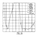
- FIG. 15 illustrates the retractable antenna of FIG. 13 in an extended position.
- FIG. 16 is a VSWR plot for the extended antenna of FIG. 15 .
- FIG. 17 illustrates a radio communications device according to further embodiments of the present invention.
- FIGS. 1 and 2 illustrate an antenna 100 according to some embodiments of the present invention.
- the antenna includes a conductor loop 110 coupled to a monopole 120 having a length c at a common feedpoint 150 .
- the conductor loop 110 is positioned overlying and substantially parallel to a ground plane 140 and separated therefrom by a distance h.
- the conductor loop 110 is shown as having a generally rectangular configuration with side dimensions a, a′, b, and b′.
- the antenna 100 further includes a helical element 130 that is wrapped around (e.g., coaxial with) the monopole 120 and also coupled to the common feedpoint 150 .
- the helical element 130 may be included or omitted in various embodiments of the present invention depending, for example, on whether a lower frequency operating band is desired.
- FIG. 3 shows a VSWR plot for a prototype antenna configured along the lines illustrated in FIGS. 1 and 2 , wherein the ground plane 140 is rectangular with dimensions of 110 mm by 40 mm, and wherein the dimensions a, a′, b, b′ are as follows:
- the prototype antenna exhibits a desirable VSWR that is 3 or less in a frequency range from about 1.5 GHz to about 2.5 GHz, which encompasses GPS, DCS, PCS, UMTS and Bluetooth frequencies. This may be attributable to the combination of the conductor loop and the monopole, i.e., the conductor loop induces a resonance in itself and the monopole at these frequencies due to reflections caused by a corner in the conductor loop.
- a helical element may be added to provide an additional band in a frequency range from around 800 MHz to around 900 MHz.
- the helical element 130 can provide a desirable VSWR less than 3 over a frequency range from about 800 MHz to around 900 MHz.
- FIG. 4 illustrates an antenna 400 according to further embodiments of the present invention, including a commonly-fed monopole 420 and rectangular conductor loop 410 overlying a rectangular ground plane 430 having dimensions of 40 mm by 110 mm formed on a substrate.
- a commonly-fed monopole 420 and rectangular conductor loop 410 overlying a rectangular ground plane 430 having dimensions of 40 mm by 110 mm formed on a substrate.
- the antenna 400 does not include a helical antenna.
- FIG. 5 illustrates VSWR characteristics for such an antenna.
- FIG. 6 illustrates a VSWR characteristic of a modification of the antenna 400 wherein antenna dimensions are doubled to have 50% bandwidth at a center resonant frequency of around 900 MHz, i.e. the bandwidth covers from about 700 MHz to about 1100 MHz.
- FIG. 7 illustrates an antenna 700 according to further embodiments of the invention, including a commonly-fed monopole 720 and rectangular conductor loop 710 overlying a rectangular ground plane 730 having dimensions of 80 mm by 120 mm formed on a substrate.
- a commonly-fed monopole 720 and rectangular conductor loop 710 overlying a rectangular ground plane 730 having dimensions of 80 mm by 120 mm formed on a substrate.
- Such a configuration may be suitable for use in, for example, a wireless PDA.
- FIG. 8 illustrates VSWR characteristics for such an antenna.
- FIG. 9 illustrates an antenna 900 according to further embodiments of the invention, including a commonly-fed monopole 920 and rectangular conductor loop 910 overlying a rectangular ground plane 630 having dimensions of 8 in by 12 in formed on a substrate. Such a configuration may be suitable for use in, for example, a laptop or notebook computer.
- FIG. 10 illustrates VSWR characteristics for such an antenna.
- FIG. 11 illustrates an antenna arrangement according to further embodiments of the present invention, in particular, one suitable for use in an radio communications device, such as a cellular telephone, that has a frame in the form of a clamshell housing comprising first and second housing portions 1150 a , 1150 b that are rotatably coupled by a hinge (not shown).
- An antenna 1100 includes a commonly fed monopole 1120 and rectangular conductor loop 1110 overlying a first ground plane portion 1140 a that is housed in the first clamshell housing portion 1150 a .
- a second ground plane portion 1140 b is housed in the second clamshell housing portion 1150 b and is coupled to the first ground plane portion 1140 a by a ground plane conductor 1140 c .
- a helical element 1130 is commonly fed with the monopole 1120 and the conductor loop 1110 , and is arranged coaxial with the monopole 1120 .
- the monopole 1120 and the helical element 1130 are arranged to extend off the ground plane portion 1140 a , and are arranged parallel to an axis of rotation of the clamshell hinge that joins the housing portions 1150 a , 1150 b .
- a radio communications circuit (not shown) may be included in the housing 1150 a , 1150 b and connected to a common feedpoint of the conductor loop 1110 , monopole 1120 and helical 1130 elements.
- FIG. 12 illustrates simulated VSWR for the antenna configuration of FIG. 11 .
- FIG. 13 illustrates an antenna arrangement according to further embodiments of the present invention, in particular, a retractable antenna 1300 suitable for use in a radio communications device, such as a cellular telephone.
- the antenna 1300 includes a retractable monopole 1310 , a helical element 1330 , and a rectangular conductor loop 1320 . These elements are configured to be feed from a feed 1340 .
- the conductor loop 1320 overlies a first ground plane portion 1350 a , which is connected to a second ground plane portion 1350 b by a ground plane conductor 1355 .
- a radio communications circuit (not shown) may be coupled to the feed 1340 .
- FIG. 14 illustrates simulated VSWR for the antenna 1300 for the retracted position shown in FIG. 13 .
- FIG. 15 illustrates the antenna 1300 in an extended position
- FIG. 16 illustrates simulated VSWR for the antenna 1300 in the extended position.
- the retractable monopole 1310 When the retractable monopole 1310 is in the retracted position ( FIG. 13 ), the helical element 1330 is connected to the loop 1320 and the common feed 1340 , and the monopole 1310 is disconnected. As shown in FIG. 14 , this produces a VSWR less than 2.5 across 850 MHz, GPS, 1800 MHz, 1900 MHz, UMTS and BT bands.
- the monopole 1310 is fully extended as shown in FIG. 15 , the monopole 1310 is connected to the loop 1320 and the feed 1340 , and the helical element 1330 is disconnected.
- the corresponding VSWR is less than 2.6 across the 850 MHz, 1800 MHz, 1900 MHz, UMTS and BT bands, as shown in FIG. 16 .
- the retractable monopole 1310 may comprise a quarter-wave monopole (e.g., for 850 or 900 MHz band), while the helical element 1330 may be dual-band for 850/1900 MHz or 900/1800 MHz bands.
- the combination of the monopole 1310 , the loop 1320 and the helical element 1330 may be used for a combination of 850/1800/1900/UMTS/BT bands or a combination of 900/1800/1900/UMTS/BT bands.
- the dimensions of the loop 1320 may be similar to those of the loop of FIGS. 1 and 2 .
- the configuration illustrated in FIGS. 13 and 15 may be particularly advantageous when used in a clamshell device (e.g., a cellphone).
- a user may pull the retractable monopole 1310 in, for example, a rural area or fringe area, to improve communication of the device.
- FIG. 17 illustrates a radio communications device 1700 according to further embodiments of the present invention.
- the device 1700 includes a frame 1710 (e.g., a housing or other support structure) that supports a radio communications circuit 1720 .
- the radio communications circuit 1720 may be operatively coupled to other electronic components, such as a processor 1730 and user interface circuitry 1740 . It will be appreciated that these components may be arranged in a number of different ways.
- the radio communications circuit 1720 is coupled to a common feedpoint 1755 for a conductor loop 1751 (overlying a ground plane 1754 ), a monopole 1752 and a helical antenna element 1753 .
- the device 1700 may take a number of forms, including, but not limited to, a mobile terminal (MT) device (e.g. a cellular telephone), a PDA, a desktop computer, a laptop computer, a notebook computer, a PCMCIA card, and a PCI bus card.
- MT mobile terminal
- PDA personal area network
- desktop computer e.g. a cellular telephone
- laptop computer e.g. a laptop computer
- notebook computer e.g. a notebook computer
- PCMCIA card e.g. a PCMCIA card
- PCI bus card e.g. a PCI bus card
Landscapes
- Physics & Mathematics (AREA)
- Electromagnetism (AREA)
- Engineering & Computer Science (AREA)
- Computer Networks & Wireless Communication (AREA)
- Support Of Aerials (AREA)
- Details Of Aerials (AREA)
- Variable-Direction Aerials And Aerial Arrays (AREA)
Priority Applications (6)
| Application Number | Priority Date | Filing Date | Title |
|---|---|---|---|
| US10/691,150 US7592958B2 (en) | 2003-10-22 | 2003-10-22 | Multi-band antennas and radio apparatus incorporating the same |
| EP04756314A EP1678783B1 (de) | 2003-10-22 | 2004-06-28 | Mehrband-antennen und diese benutzende funkgeräte |
| PCT/US2004/020802 WO2005045990A1 (en) | 2003-10-22 | 2004-06-28 | Multi-band antennas and radio apparatus incorporating the same |
| DE602004024106T DE602004024106D1 (de) | 2003-10-22 | 2004-06-28 | Mehrband-antennen und diese benutzende funkgeräte |
| JP2006536550A JP2007509568A (ja) | 2003-10-22 | 2004-06-28 | マルチバンドアンテナ及びこれを実装する無線装置 |
| CN200480031052XA CN1871742B (zh) | 2003-10-22 | 2004-06-28 | 多频带天线和包含该多频带天线的无线电装置 |
Applications Claiming Priority (1)
| Application Number | Priority Date | Filing Date | Title |
|---|---|---|---|
| US10/691,150 US7592958B2 (en) | 2003-10-22 | 2003-10-22 | Multi-band antennas and radio apparatus incorporating the same |
Publications (2)
| Publication Number | Publication Date |
|---|---|
| US20050088346A1 US20050088346A1 (en) | 2005-04-28 |
| US7592958B2 true US7592958B2 (en) | 2009-09-22 |
Family
ID=34521811
Family Applications (1)
| Application Number | Title | Priority Date | Filing Date |
|---|---|---|---|
| US10/691,150 Expired - Fee Related US7592958B2 (en) | 2003-10-22 | 2003-10-22 | Multi-band antennas and radio apparatus incorporating the same |
Country Status (6)
| Country | Link |
|---|---|
| US (1) | US7592958B2 (de) |
| EP (1) | EP1678783B1 (de) |
| JP (1) | JP2007509568A (de) |
| CN (1) | CN1871742B (de) |
| DE (1) | DE602004024106D1 (de) |
| WO (1) | WO2005045990A1 (de) |
Families Citing this family (8)
| Publication number | Priority date | Publication date | Assignee | Title |
|---|---|---|---|---|
| US7199762B2 (en) * | 2005-08-24 | 2007-04-03 | Motorola Inc. | Wireless device with distributed load |
| NO327900B1 (no) * | 2007-09-20 | 2009-10-19 | Wireless Patient Recording Med | Anordning ved antenne for anvendelse naer et delvis ledende materiale |
| GB0806335D0 (en) * | 2008-04-08 | 2008-05-14 | Antenova Ltd | A novel planar radio-antenna module |
| JP5645100B2 (ja) * | 2010-01-06 | 2014-12-24 | 日立金属株式会社 | アンテナ装置、並びにこれを用いた通信機器 |
| US8644894B2 (en) | 2010-03-12 | 2014-02-04 | Blackberry Limited | Mobile wireless device with multi-band antenna and related methods |
| US20130009840A1 (en) * | 2010-03-24 | 2013-01-10 | Hytera Communications Corp., Ltd. | Whip dual-band antenna |
| US8870069B2 (en) | 2012-08-22 | 2014-10-28 | Symbol Technologies, Inc. | Co-located antenna arrangement |
| KR101879352B1 (ko) * | 2017-05-17 | 2018-07-18 | 에더트로닉스코리아 (주) | 공통 급전 구조를 포함하는 안테나 장치 |
Citations (21)
| Publication number | Priority date | Publication date | Assignee | Title |
|---|---|---|---|---|
| US5300936A (en) * | 1992-09-30 | 1994-04-05 | Loral Aerospace Corp. | Multiple band antenna |
| US5914692A (en) * | 1997-01-14 | 1999-06-22 | Checkpoint Systems, Inc. | Multiple loop antenna with crossover element having a pair of spaced, parallel conductors for electrically connecting the multiple loops |
| EP0945917A2 (de) | 1998-02-27 | 1999-09-29 | Samsung Electronics Co., Ltd. | Antennenanordnung und Mobilfunkendgerät |
| US6005521A (en) * | 1996-04-25 | 1999-12-21 | Kyocera Corporation | Composite antenna |
| US6054958A (en) * | 1997-09-10 | 2000-04-25 | Ericsson Inc. | Quarter-wave quarter-wave retractable antenna |
| GB2347560A (en) | 1999-02-08 | 2000-09-06 | Nokia Mobile Phones Ltd | Radio apparatus |
| US6212400B1 (en) * | 1997-04-15 | 2001-04-03 | Siemens Aktiengesellschaft | Antenna device for mobile radio telephone devices |
| US6239755B1 (en) * | 1999-10-28 | 2001-05-29 | Qualcomm Incorporated | Balanced, retractable mobile phone antenna |
| JP2001230613A (ja) | 2000-02-18 | 2001-08-24 | Matsushita Electric Ind Co Ltd | アンテナ装置及び携帯無線機 |
| US6317086B1 (en) * | 1999-02-01 | 2001-11-13 | Mrw Technologies Ltd. | Extendible and contractible wireless antenna |
| US6424300B1 (en) * | 2000-10-27 | 2002-07-23 | Telefonaktiebolaget L.M. Ericsson | Notch antennas and wireless communicators incorporating same |
| EP1237224A1 (de) | 2001-02-14 | 2002-09-04 | Siemens Aktiengesellschaft | Antenne und Verfahren zu deren Herstellung |
| US6459916B1 (en) * | 1996-04-16 | 2002-10-01 | Kyocera Corporation | Portable radio communication device |
| JP2003008329A (ja) | 2001-06-27 | 2003-01-10 | Kenwood Corp | 複合アンテナ |
| US20030117325A1 (en) * | 2001-11-02 | 2003-06-26 | Young-Min Jo | Dual band spiral-shaped antenna |
| US6590541B1 (en) * | 1998-12-11 | 2003-07-08 | Robert Bosch Gmbh | Half-loop antenna |
| US20040125020A1 (en) * | 2002-06-04 | 2004-07-01 | Hendler Jason M. | Wideband printed monopole antenna |
| US6774856B2 (en) * | 2002-05-15 | 2004-08-10 | Kosan I & T Co., Ltd. | External mounting type microchip dual band antenna assembly |
| US6822614B2 (en) * | 2002-01-04 | 2004-11-23 | Darfon Electronics Corp. | Loop antenna |
| US20040263403A1 (en) * | 2003-06-27 | 2004-12-30 | Imtiaz Zafar | Mobile satellite radio antenna system |
| US6990363B2 (en) * | 2000-12-04 | 2006-01-24 | Nec Corporation | Wireless communication device with an improved antenna structure |
Family Cites Families (6)
| Publication number | Priority date | Publication date | Assignee | Title |
|---|---|---|---|---|
| JP3671509B2 (ja) * | 1996-03-05 | 2005-07-13 | ソニー株式会社 | アンテナ装置 |
| SE511131C2 (sv) * | 1997-11-06 | 1999-08-09 | Ericsson Telefon Ab L M | Portabel elektronisk kommunikationsanordning med flerbandigt antennsystem |
| BR9917171A (pt) * | 1998-02-27 | 2001-12-04 | Motorola Inc | Antena adaptada para operar em várias bandas defrequência |
| JP3730112B2 (ja) * | 2000-11-30 | 2005-12-21 | 三菱電機株式会社 | アンテナ装置 |
| JP2003124736A (ja) * | 2001-10-12 | 2003-04-25 | Murata Mfg Co Ltd | 表面実装型アンテナおよびそれを用いた通信機 |
| US6618019B1 (en) * | 2002-05-24 | 2003-09-09 | Motorola, Inc. | Stubby loop antenna with common feed point |
-
2003
- 2003-10-22 US US10/691,150 patent/US7592958B2/en not_active Expired - Fee Related
-
2004
- 2004-06-28 DE DE602004024106T patent/DE602004024106D1/de active Active
- 2004-06-28 CN CN200480031052XA patent/CN1871742B/zh not_active Expired - Fee Related
- 2004-06-28 EP EP04756314A patent/EP1678783B1/de not_active Expired - Fee Related
- 2004-06-28 JP JP2006536550A patent/JP2007509568A/ja active Pending
- 2004-06-28 WO PCT/US2004/020802 patent/WO2005045990A1/en active Application Filing
Patent Citations (21)
| Publication number | Priority date | Publication date | Assignee | Title |
|---|---|---|---|---|
| US5300936A (en) * | 1992-09-30 | 1994-04-05 | Loral Aerospace Corp. | Multiple band antenna |
| US6459916B1 (en) * | 1996-04-16 | 2002-10-01 | Kyocera Corporation | Portable radio communication device |
| US6005521A (en) * | 1996-04-25 | 1999-12-21 | Kyocera Corporation | Composite antenna |
| US5914692A (en) * | 1997-01-14 | 1999-06-22 | Checkpoint Systems, Inc. | Multiple loop antenna with crossover element having a pair of spaced, parallel conductors for electrically connecting the multiple loops |
| US6212400B1 (en) * | 1997-04-15 | 2001-04-03 | Siemens Aktiengesellschaft | Antenna device for mobile radio telephone devices |
| US6054958A (en) * | 1997-09-10 | 2000-04-25 | Ericsson Inc. | Quarter-wave quarter-wave retractable antenna |
| EP0945917A2 (de) | 1998-02-27 | 1999-09-29 | Samsung Electronics Co., Ltd. | Antennenanordnung und Mobilfunkendgerät |
| US6590541B1 (en) * | 1998-12-11 | 2003-07-08 | Robert Bosch Gmbh | Half-loop antenna |
| US6317086B1 (en) * | 1999-02-01 | 2001-11-13 | Mrw Technologies Ltd. | Extendible and contractible wireless antenna |
| GB2347560A (en) | 1999-02-08 | 2000-09-06 | Nokia Mobile Phones Ltd | Radio apparatus |
| US6239755B1 (en) * | 1999-10-28 | 2001-05-29 | Qualcomm Incorporated | Balanced, retractable mobile phone antenna |
| JP2001230613A (ja) | 2000-02-18 | 2001-08-24 | Matsushita Electric Ind Co Ltd | アンテナ装置及び携帯無線機 |
| US6424300B1 (en) * | 2000-10-27 | 2002-07-23 | Telefonaktiebolaget L.M. Ericsson | Notch antennas and wireless communicators incorporating same |
| US6990363B2 (en) * | 2000-12-04 | 2006-01-24 | Nec Corporation | Wireless communication device with an improved antenna structure |
| EP1237224A1 (de) | 2001-02-14 | 2002-09-04 | Siemens Aktiengesellschaft | Antenne und Verfahren zu deren Herstellung |
| JP2003008329A (ja) | 2001-06-27 | 2003-01-10 | Kenwood Corp | 複合アンテナ |
| US20030117325A1 (en) * | 2001-11-02 | 2003-06-26 | Young-Min Jo | Dual band spiral-shaped antenna |
| US6822614B2 (en) * | 2002-01-04 | 2004-11-23 | Darfon Electronics Corp. | Loop antenna |
| US6774856B2 (en) * | 2002-05-15 | 2004-08-10 | Kosan I & T Co., Ltd. | External mounting type microchip dual band antenna assembly |
| US20040125020A1 (en) * | 2002-06-04 | 2004-07-01 | Hendler Jason M. | Wideband printed monopole antenna |
| US20040263403A1 (en) * | 2003-06-27 | 2004-12-30 | Imtiaz Zafar | Mobile satellite radio antenna system |
Non-Patent Citations (2)
| Title |
|---|
| Communication pursuant to Article 94(3) EPC (4 pages) corresponding to European Patent Application No. 04756314.3; Dated: Dec. 16, 2008. |
| Notification of Transmittal of the International Search Report and the Written Opinion of the International Searching Authority, or the Declaration, PCT/US2004/020802, Nov. 23, 2004. |
Also Published As
| Publication number | Publication date |
|---|---|
| EP1678783B1 (de) | 2009-11-11 |
| CN1871742B (zh) | 2012-02-15 |
| JP2007509568A (ja) | 2007-04-12 |
| WO2005045990A1 (en) | 2005-05-19 |
| EP1678783A1 (de) | 2006-07-12 |
| CN1871742A (zh) | 2006-11-29 |
| US20050088346A1 (en) | 2005-04-28 |
| DE602004024106D1 (de) | 2009-12-24 |
Similar Documents
| Publication | Publication Date | Title |
|---|---|---|
| US6552686B2 (en) | Internal multi-band antenna with improved radiation efficiency | |
| US7605766B2 (en) | Multi-band antenna device for radio communication terminal and radio communication terminal comprising the multi-band antenna device | |
| US7411556B2 (en) | Multi-band monopole antenna for a mobile communications device | |
| KR100607097B1 (ko) | 안테나시스템 및 이 안테나시스템을 갖춘 무선통신장치 | |
| US7319432B2 (en) | Multiband planar built-in radio antenna with inverted-L main and parasitic radiators | |
| US7415248B2 (en) | Multiband radio antenna with a flat parasitic element | |
| US7388543B2 (en) | Multi-frequency band antenna device for radio communication terminal having wide high-band bandwidth | |
| JP3266190B2 (ja) | 折り畳み式移動電話 | |
| US6348897B1 (en) | Multi-function antenna system for radio communication device | |
| US8922449B2 (en) | Communication electronic device and antenna structure thereof | |
| EP2381529B1 (de) | Kommunikationsstrukturen mit Antennen mit separaten Antennenzweigen, die gekoppelt werden, um Leiter zu speisen und erden | |
| US20070139280A1 (en) | Switchable planar antenna apparatus for quad-band GSM applications | |
| US20110128190A1 (en) | Wireless communication terminal with a split multi-band antenna having a single rf feed node | |
| US8890766B2 (en) | Low profile multi-band antennas and related wireless communications devices | |
| US7639188B2 (en) | Radio antenna for a communication terminal | |
| US7592958B2 (en) | Multi-band antennas and radio apparatus incorporating the same | |
| EP1345282A1 (de) | Eingebaute Mehrband-Planarantenne mit Inverted-L-Haupt- und Parasitär- Antennenelementen | |
| US20120056797A1 (en) | Frequency-tunable antenna | |
| Ren et al. | High performance multiband radio antenna | |
| US20080129628A1 (en) | Wideband antenna for mobile devices |
Legal Events
| Date | Code | Title | Description |
|---|---|---|---|
| AS | Assignment |
Owner name: SONY ERICSSON MOBILE COMMUNICATIONS AB, SWEDEN Free format text: ASSIGNMENT OF ASSIGNORS INTEREST;ASSIGNORS:HWANG, HUAN-SHENG;SADLER, ROBERT A.;REEL/FRAME:014638/0368;SIGNING DATES FROM 20031007 TO 20031008 |
|
| FEPP | Fee payment procedure |
Free format text: PAYER NUMBER DE-ASSIGNED (ORIGINAL EVENT CODE: RMPN); ENTITY STATUS OF PATENT OWNER: LARGE ENTITY Free format text: PAYOR NUMBER ASSIGNED (ORIGINAL EVENT CODE: ASPN); ENTITY STATUS OF PATENT OWNER: LARGE ENTITY |
|
| STCF | Information on status: patent grant |
Free format text: PATENTED CASE |
|
| CC | Certificate of correction | ||
| FPAY | Fee payment |
Year of fee payment: 4 |
|
| FPAY | Fee payment |
Year of fee payment: 8 |
|
| FEPP | Fee payment procedure |
Free format text: MAINTENANCE FEE REMINDER MAILED (ORIGINAL EVENT CODE: REM.); ENTITY STATUS OF PATENT OWNER: LARGE ENTITY |
|
| LAPS | Lapse for failure to pay maintenance fees |
Free format text: PATENT EXPIRED FOR FAILURE TO PAY MAINTENANCE FEES (ORIGINAL EVENT CODE: EXP.); ENTITY STATUS OF PATENT OWNER: LARGE ENTITY |
|
| STCH | Information on status: patent discontinuation |
Free format text: PATENT EXPIRED DUE TO NONPAYMENT OF MAINTENANCE FEES UNDER 37 CFR 1.362 |
|
| FP | Lapsed due to failure to pay maintenance fee |
Effective date: 20210922 |