US7538774B2 - Virtual visual point image generating method and 3-d image display method and device - Google Patents
Virtual visual point image generating method and 3-d image display method and device Download PDFInfo
- Publication number
- US7538774B2 US7538774B2 US10/561,344 US56134404A US7538774B2 US 7538774 B2 US7538774 B2 US 7538774B2 US 56134404 A US56134404 A US 56134404A US 7538774 B2 US7538774 B2 US 7538774B2
- Authority
- US
- United States
- Prior art keywords
- projection
- image
- points
- viewpoint
- color information
- Prior art date
- Legal status (The legal status is an assumption and is not a legal conclusion. Google has not performed a legal analysis and makes no representation as to the accuracy of the status listed.)
- Active, expires
Links
Images


Classifications
-
- H—ELECTRICITY
- H04—ELECTRIC COMMUNICATION TECHNIQUE
- H04N—PICTORIAL COMMUNICATION, e.g. TELEVISION
- H04N13/00—Stereoscopic video systems; Multi-view video systems; Details thereof
-
- G—PHYSICS
- G06—COMPUTING; CALCULATING OR COUNTING
- G06T—IMAGE DATA PROCESSING OR GENERATION, IN GENERAL
- G06T15/00—3D [Three Dimensional] image rendering
- G06T15/10—Geometric effects
- G06T15/20—Perspective computation
- G06T15/205—Image-based rendering
-
- G—PHYSICS
- G06—COMPUTING; CALCULATING OR COUNTING
- G06T—IMAGE DATA PROCESSING OR GENERATION, IN GENERAL
- G06T17/00—Three dimensional [3D] modelling, e.g. data description of 3D objects
-
- G—PHYSICS
- G06—COMPUTING; CALCULATING OR COUNTING
- G06T—IMAGE DATA PROCESSING OR GENERATION, IN GENERAL
- G06T7/00—Image analysis
- G06T7/50—Depth or shape recovery
- G06T7/55—Depth or shape recovery from multiple images
- G06T7/593—Depth or shape recovery from multiple images from stereo images
-
- H—ELECTRICITY
- H04—ELECTRIC COMMUNICATION TECHNIQUE
- H04N—PICTORIAL COMMUNICATION, e.g. TELEVISION
- H04N13/00—Stereoscopic video systems; Multi-view video systems; Details thereof
- H04N13/20—Image signal generators
- H04N13/204—Image signal generators using stereoscopic image cameras
- H04N13/243—Image signal generators using stereoscopic image cameras using three or more 2D image sensors
-
- G—PHYSICS
- G02—OPTICS
- G02B—OPTICAL ELEMENTS, SYSTEMS OR APPARATUS
- G02B30/00—Optical systems or apparatus for producing three-dimensional [3D] effects, e.g. stereoscopic images
- G02B30/50—Optical systems or apparatus for producing three-dimensional [3D] effects, e.g. stereoscopic images the image being built up from image elements distributed over a 3D volume, e.g. voxels
Definitions
- the present invention relates to a technology for estimating information on a three-dimensional shape of an object from plural images to generate an image using the information.
- the technology of the present invention can be applied to a system that supports visual communications such as a TV phone and the like.
- the DFD is a display in which plural image display planes are layered at some intervals (for example, refer to document 1: Japanese Patent No. 3022558).
- the DFD can be roughly classified into a brightness modulation type and a transmission type.
- a two-dimensional image of the object is displayed on each image display plane.
- the DFD is the brightness modulation type
- brightness of each of pixels overlapping when viewed from a predetermined viewpoint of an observer (reference viewpoint) is set in a ratio according to the shape of the object in the depth direction for displaying the pixels. Accordingly, as to a point existing on the object, brightness of the pixel on an image display plane existing near from the observer becomes large, and as to another point, the brightness of the pixel on a display plane existing farther from the observer becomes large.
- the observer who observes images displayed on each image display plane of the DFD can see a stereoscopic image (three-dimensional image) of the object.
- transmittance of each of pixels, on each image display plane, overlapping when viewed from a predetermined viewpoint of the observer (reference viewpoint) is set according to the shape of the object in the depth direction so as to display the pixels.
- the method for displaying the three-dimensional image of the object there is a method for displaying two images having parallax corresponding to an interval of right and left eyes of the observer on a screen such as a liquid crystal display and the like.
- each of the images can be generated using the model.
- the three-dimensional shape of the object is not known, it is necessary to obtain the three dimensional shape of the object, namely, a geometrical model of the object before generating each image.
- the geometrical model of the object is represented as a set of basic figures called polygon or voxel, for example.
- Shape from X there are various methods for obtaining the geometrical model of the object based on the plural images, and many studies are being performed as Shape from X in the field of the computer vision.
- the stereo method is a representative model obtaining method (refer to document 2 : Takeo Kanade et al.: “Virtualized Reality: Constructing Virtual Worlds from Real Scenes,” IEEE MultiMedia, Vol. 4, No. 1, pp. 34-37, 1997, for example).
- the geometrical model of the object is obtained based on plural images of the object taken from different viewpoints.
- a distance from the reference viewpoint for obtaining the model to each point of the object is calculated using triangulation techniques by performing corresponding point matching, that is, by associating points (pixels) on each image.
- the geometrical model of the object is not immediately obtained using the stereo method. A group of points on the surface of the object is obtained. Therefore, it is necessary to determine structural information indicating how the points included in the point group are connected and what surface is formed in order to obtain the geometrical model of the object (refer to document 3 : Katusi Ikeuchi “Model generation of real object using images”, Journal of the Robotics Society of Japan, Vol. 16, No. 6, pp. 763-766, 1998, for example).
- the apparatus (computer) for generating the image should perform complicated processing such as application of the shape of the object, statistical processing and the like. Therefore, high computing power is necessary.
- Shape from Silhouette for determining a region that the object occupies in the space based on an outline of the object in each image taken from plural viewpoints (to be referred to as Shape from Silhouette method hereinafter) (refer to document 4: Potmesil, M: “Generating Octree Models of 3D Objects from their Silhouettes in a Sequence of Images,” CVGIP 40, pp. 1-29, 1987, for example).
- the geometrical model of the object obtained by the Shape from Silhouette method is represented as a set of small cubes called voxels.
- the geometrical model of the object is represented by the voxels, large amount of data are required for representing the three-dimensional shape of the object. Therefore, high computing power is required for obtaining the geometrical model of the object using the Shape from Silhouette method.
- the texture mapping is a method for setting the projection planes of the multi-layered structure, and mapping each partial image (texture image) cut out from the taken image to a projection plane corresponding to a distance of the object appearing in the texture image so as to obtain stereoscopic visual effects.
- this method has advantages in that adequately high-speed processing can be performed even by graphics hardware in a generally widespread personal computer and in that handling of data is easy.
- a contrivance is proposed in which a value (depth value) in addition to color information of R (red), G (green) and B (blue) is added for each pixel of the texture image for detailed shape, for example, while rough shape is represented by the projection planes (planes).
- a method is proposed in which positions of pixels of each texture image are changed according to the depth value so as to represent detailed depths that cannot be fully represented only by the multi-layered planes.
- transmittance of each pixel is set according to the depth value to represent detailed depths that cannot be fully represented only by the multi-layered planes.
- the method for obtaining the geometrical model of the object using the stereo method is susceptible to the shape of the object and the texture of the surface of the object, and surrounding environment of the object so that highly reliable information is not necessarily obtained for any shape of the object and for every point of the object (refer to document 7 : Masatoshi Okutomi: “Why is stereo difficult?”, Journal of the Robotics Society of Japan, Vol. 16, No. 6, pp. 39-43, 1998, for example).
- the shape from Silhouette method it is difficult in itself to correctly extract the outline of the object against the background on the image.
- the method for correctly extracting the outline is a main research task in the computer vision field now as in the past. That is, the geometrical model of the object obtained by the Shape from Silhouette method is a model obtained from an inaccurate outline, and the reliability is not high. Therefore, there is a problem in that the image generated from the geometrical model of the object obtained by the Shape from Silhouette method does not have sufficiently satisfactory quality.
- the depth value provided for each texture pixel is known. That is, the method assumes that the shape of the object is accurately obtained. Therefore, when the shape of the object is not known, it is necessary to obtain the geometrical model of the object first. As a result, when there is an unreliable portion in the shape estimation of the object, there is a case that the texture image is mapped to an incorrect projection plane, so that there is a problem in that the generated image is remarkably deteriorated.
- processing for mapping images on the multi-layered projection planes can be performed at high speed.
- higher processing ability is required for accurately obtaining the shape of the object in the processing for obtaining the depth values.
- An object of the present invention is to provide a technology that can decrease remarkable deterioration of image quality that occurs at a part where the reliability of estimation of the shape of the object is low when generating the image of the object by obtaining the three-dimensional shape of the object from plural images.
- Another object of the present invention is to provide a technology that can generate the image having small partial deterioration of image quality in a short time even by using an apparatus having low processing performance when generating the image of the object by obtaining the three-dimensional shape of the object from plural images.
- Still another object of the present invention is to provide a technology that can downsize an image-taking apparatus for taking images used for obtaining the geometrical model of the object so as to simplify the apparatus configuration.
- the present invention is configured as a virtual viewpoint image generation method including:
- the step of generating the virtual viewpoint image including:
- the image generation method of the present invention can be configured as an image generation method including:
- the step of obtaining the three-dimensional shape of the object including:
- the step of calculating the correlation degree including:
- the step of determining the existence probability including:
- the present invention can be configured as an image generation method including:
- the step of obtaining the three-dimensional shape of the object including:
- the step of generating the image of the object viewed from the virtual viewpoint including:
- the present invention can be configured as an image generation method including:
- the step of obtaining the three-dimensional shape of the object including:
- the step of determining the existence probability including:
- the present invention can be configured as a three-dimensional image display method including:
- the step of obtaining the three-dimensional shape of the object including:
- the step of generating the two-dimensional images including:
- the step of presenting the three-dimensional image of the object including:
- the present invention when generating the image of the object by obtaining the three-dimensional shape of the object from plural images, it becomes possible to reduce remarkable deterioration of image quality that occurs in a part where the reliability of estimation of the shape of the object is low. In addition, it becomes possible to generate the image having small partial deterioration of image quality in a short time even by using an apparatus having low processing performance. Further, it becomes possible to downsize a taking apparatus for taking images used for obtaining the geometrical model of the object so as to simplify the apparatus configuration.
- FIG. 1 is a diagram for explaining problems a conventional virtual viewpoint image
- FIG. 2 is a schematic diagram for explaining the principle of the virtual viewpoint image generation method of the first embodiment, and is a diagram showing examples of projection plane group, camera, reference viewpoint, projection point and corresponding point;
- FIG. 3A and FIG. 3B are diagrams for explaining the principle of the virtual viewpoint image generation method of the first embodiment
- FIG. 4A and FIG. 4B are diagrams for explaining the principle of the virtual viewpoint image generation method of the first embodiment, and are diagrams showing an example of mixing processing according to transparency of projection points;
- FIG. 5 is a schematic diagram for explaining the principle of the virtual viewpoint image generation method of the first embodiment, and is a diagram showing examples of object, projection plane group, reference viewpoint, virtual projection point and projection point;
- FIG. 6 is a schematic diagram showing an outline configuration of a virtual viewpoint image generation apparatus of an embodiment 1-1, and is a block diagram showing a configuration of the inside of the image generation apparatus;
- FIG. 7 is a schematic diagram showing an outline configuration of a virtual viewpoint image generation apparatus of an embodiment 1-1, and is a configuration example of a system using the image generation apparatus:
- FIG. 8 is a schematic diagram for explaining the mathematical principle model of the virtual viewpoint image generation method using the virtual viewpoint image generation apparatus of the embodiment 1-1, and is a diagram showing an example of projection conversion;
- FIG. 9 is a schematic diagram for explaining the mathematical principle model of the virtual viewpoint image generation method using the virtual viewpoint image generation apparatus of the embodiment 1-1, and is a diagram showing an example of coordinates conversion;
- FIG. 10 is a schematic diagram for explaining the generation processing procedure for the virtual viewpoint image of the embodiment 1-1, and is a flow diagram showing the whole generation processing;
- FIG. 11 is a schematic diagram for explaining the generation processing procedure for the virtual viewpoint image of the embodiment 1-1, and is a concrete flow diagram showing steps for generating the virtual viewpoint image;
- FIG. 12 is a schematic diagram for explaining the generation processing procedure for the virtual viewpoint image of the embodiment 1-1, and is a diagram showing an example of a setting method of the projection plane;
- FIG. 13 is a schematic diagram for explaining the generation processing procedure for the virtual viewpoint image of the embodiment 1-1, and is a diagram showing examples-of projection points, projection point series and a set of projection point series;
- FIG. 14 is a schematic diagram for explaining the generation processing procedure for the virtual viewpoint image of the embodiment 1-1, and is a diagram showing examples of a reference viewpoint, projection points and angles based on various camera positions for explaining mixing processing of color information;
- FIG. 15 is a schematic diagram for explaining the generation processing procedure for the virtual viewpoint image of the embodiment 1-1, and is a diagram showing an example of corresponding point matching processing;
- FIG. 16 is a schematic diagram for explaining the generation processing procedure for the virtual viewpoint image of the embodiment 1-1, and is a diagram for explaining rendering processing;
- FIG. 17 is a schematic diagram for explaining the generation processing procedure for the virtual viewpoint image of the embodiment 1-1, and is a diagram showing an example of a generated virtual viewpoint image;
- FIG. 18 is a schematic diagram showing an application example of a system to which the virtual viewpoint image generation apparatus of the embodiment 1-1 is applied;
- FIG. 19A is a flow diagram indicating processing that is a feature of the embodiment 1-2
- FIG. 19B is a flow diagram showing an example of concrete processing procedure of steps for determining transparency information
- FIG. 20 is a schematic diagram for explaining the virtual viewpoint image generation method of the embodiment 1-3, and is a diagram showing examples of projection plane group, reference viewpoint, virtual viewpoint and projection points;
- FIG. 21 is a schematic diagrams for explaining the principle of the image generation method of the second embodiment, and is a diagram for explaining a concept of a method for generating the image to be displayed;
- FIG. 22 is a schematic diagram for explaining the principle of the image generation method of the second embodiment, and is a diagram representing FIG. 21 in two-dimensional;
- FIG. 23A and FIG. 23B are diagrams for explaining a method for obtaining the correlation degree of the corresponding points
- FIG. 24A and FIG. 24B are diagrams for explaining a problem when obtaining the correlation degree of the corresponding points
- FIG. 25 is a schematic diagram for explaining the principle of the image generation method of the second embodiment, and is a diagram for explaining a method for solving the problem when obtaining the correlation degree;
- FIG. 26A and FIG. 26B are diagrams for explaining an example of a method for improving accuracy of the existence probability
- FIG. 27 is a schematic diagram for explaining the principle of the image generation method of the second embodiment.
- FIG. 28 is a schematic diagram for explaining the principle of the image generation method of the second embodiment.
- FIG. 29 is a schematic diagram for explaining an image generation method of the embodiment 2-1, and is a flow diagram showing an example of a general processing procedure;
- FIG. 30 is a schematic diagram for explaining an image generation method of the embodiment 2-1, and is a flow diagram showing an example of a processing procedure of steps for determining color information and existence probability of projection points in FIG. 29 ;
- FIG. 31 is a schematic diagram for explaining an image generation method of the embodiment 2-1, and is a flow diagram showing an example of steps for determining the existence probability in FIG. 30 ;
- FIG. 32 is a schematic diagram for explaining an image generation method of the embodiment 2-1, and is a diagram showing an example foe setting a camera set;
- FIG. 33 is a schematic diagram for explaining an image generation method of the embodiment 2-1, and is a diagram for explaining a method for converting information of the projection plane to information of display plane;
- FIGS. 34A and 34B are diagrams for explaining a method for converting information of the projection plane to information of display plane
- FIG. 35 is a block diagram showing a configuration example of the image generation apparatus to which the image generation method of the embodiment 2-1 is applied;
- FIG. 36 is a diagram showing a configuration example of an image display system using the image generation apparatus to which the image generation method of the embodiment 2-1 is applied;
- FIG. 37 is a diagram showing another configuration example of an image display system using the image generation apparatus to which the image generation method of the embodiment 2-1 is applied;
- FIG. 38 is a schematic diagram for explaining an image generation method of the embodiment 2-2, and is a flow diagram showing an example of the whole processing procedure;
- FIG. 39 is a schematic diagram for explaining an image generation method of the embodiment 2-2, and is a diagram for explaining a principle of rendering;
- FIG. 40 is a schematic diagram for explaining an image generation method of the embodiment 2-2, and is a diagram for explaining problems that arise in the image generation method in this embodiment;
- FIGS. 41A and B are schematic diagrams for explaining an image generation method of the embodiment 2-2, and are diagrams for explaining a method for solving the problems that arise in the image generation method in this embodiment;
- FIG. 42 is a schematic diagram for explaining an image generation method of the embodiment 2-2, and is a flow diagram showing an example of the processing procedure for converting the existence probability to transparency;
- FIG. 43 is a schematic diagram for explaining the principal of the image generation method of the third embodiment, and is a diagram showing a setting example of the projection planes and the reference viewpoint;
- FIG. 44 is a schematic diagram for explaining the principal of the image generation method of the third embodiment, and is a diagram showing a setting example of the projection planes and the reference viewpoint;
- FIG. 45 is a schematic diagram for explaining the principal of the image generation method of the third embodiment, and is a diagram for explaining a method for determining the color information and the focusing degree of the projection point;
- FIG. 46 is a schematic diagram for explaining the principal of the image generation method of the third embodiment, and is a diagram for explaining a method of determining the existence probability of the projection point;
- FIG. 47 is a schematic diagram for explaining the principal of the image generation method of the third embodiment, and is a diagram for explaining a method of determining the existence probability of the projection point;
- FIG. 48 is a schematic diagram for explaining the principal of the image generation method of the third embodiment, and is a diagram for explaining a method of determining the existence probability of the projection point;
- FIG. 49 is a schematic diagram for explaining the principal of the image generation method of the third embodiment, and is a diagram for explaining a method for generating an image viewed from the virtual viewpoint;
- FIG. 50 is a schematic diagram for explaining the principal of the image generation method of the third embodiment, and is a diagram for explaining problems in the image generation method in the present invention
- FIG. 51 is a schematic diagram for explaining the principal of the image generation method of the third embodiment, and is a diagram for explaining a method for solving the problems in the image generation method in the present invention
- FIG. 52 is a schematic diagram for explaining the mathematical model of the image generation method of the third embodiment, and is a diagram showing relationship among projection points, corresponding points and points on the image to be generated;
- FIG. 53 is a schematic diagram for explaining the mathematical model of the image generation method of the third embodiment, and is a diagram for explaining a method for converting points on the space to pixels on the image;
- FIG. 54 is a schematic diagram for explaining the image generation method of the embodiment 3-1, and is a flow diagram showing a generation procedure for the image;
- FIG. 55 is a schematic diagram for explaining the image generation method of the embodiment 3-1, and is a diagram for explaining a method for setting the projection point series;
- FIG. 56 is a schematic diagram for explaining the image generation method of the embodiment 3-1, and is a flow diagram showing a concrete example of processing of the step 10305 of FIG. 54 ;
- FIG. 57 is a schematic diagram for explaining the image generation method of the embodiment 3-1, and is a diagram for explaining a rendering method
- FIG. 58 is a schematic diagram showing a general configuration of the apparatus for generating the image using the image generation method of the embodiment 3-1, and is a block diagram showing the configuration of the apparatus;
- FIG. 59 is a diagram for explaining a configuration example of the object image taking means the embodiment 3-1;
- FIG. 60 is a diagram for explaining a configuration example of the object image taking means the embodiment 3-1;
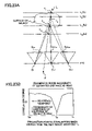
- FIG. 61 is a diagram for explaining a configuration example of the object image taking means the embodiment 3-1;
- FIG. 62 is a schematic diagram showing a general configuration of the image generation system using the image generation apparatus of the embodiment 3-1, and is a diagram showing a configuration example of the image generation system;
- FIG. 63 is a schematic diagram showing a general configuration of the image generation system using the image generation apparatus of the embodiment 3-1, and is a diagram showing another configuration example of the image generation system;
- FIG. 64 is a flow diagram showing processing of the virtual viewpoint image generation method of the embodiment 3-2;
- FIG. 65 is a schematic diagram for explaining other generation method in the image generation method in the third embodiment.
- FIG. 66 is a schematic diagram for explaining the image generation method of the embodiment 4-1, and is a flow diagram showing an example of the whole processing procedure;
- FIG. 67 is a schematic diagram for explaining the image generation method of the embodiment 4-1, and is a diagram showing an example of a method for setting the projection plane;
- FIG. 68 is a schematic diagram for explaining the image generation method of the embodiment 4-1, and is a diagram showing an example of a method for setting the projection plane;
- FIG. 69 is a schematic diagram for explaining the image generation method of the embodiment 4-1, and is a diagram for explaining a method for setting projection point series;
- FIG. 70 is a schematic diagram for explaining the image generation method of the embodiment 4-1, and is a flow diagram showing an example of processing procedure of steps for determining the color information and the existence probability of the projection point;
- FIG. 71 is a schematic diagram for explaining the image generation method of the embodiment 4-1, and is a diagram for explaining a method for determining the existence probability;
- FIG. 72 is a schematic diagram for explaining the image generation method of the embodiment 4-1, and is a diagram for explaining a method for determining the existence probability;
- FIG. 73 is a schematic diagram for explaining the image generation method of the embodiment 4-1, and is a diagram for explaining a method for determining the existence probability;
- FIG. 74 is a schematic diagram for explaining the image generation method of the embodiment 4-1, and is a diagram for explaining a method for determining the existence probability;
- FIG. 75 is a schematic diagram for explaining the image generation method of the embodiment 4-1, and is a diagram for explaining a method for generating the two-dimensional images to be displayed on each image display plane;
- FIG. 76 is a schematic diagram for explaining the image generation method of the embodiment 4-1, and is a diagram for explaining a method for generating the two-dimensional images to be displayed on each image display plane;
- FIG. 77 is a schematic diagram for explaining the image generation method of the embodiment 4-1, and is a diagram for explaining a method for generating the two-dimensional images to be displayed on each image display plane;
- FIG. 78 is a schematic diagram for explaining the image generation method of the embodiment 4-2, and is a diagram showing relationship between the projection point and the corresponding point;
- FIG. 79 is a schematic diagram for explaining the image generation method of the embodiment 4-2, and is a flow diagram showing an example of steps for determining the color information and the existence probability of the projection point;
- FIG. 80 is a schematic diagram for explaining the image generation method of the embodiment 4-2, and is a diagram for explaining a method for obtaining the existence probability;
- FIG. 81 is a schematic diagram for explaining the image generation method of the embodiment 4-2, and is a diagram for explaining a method for obtaining the existence probability;
- FIG. 82 is a schematic diagram for explaining an arbitrary viewpoint image generation method of the embodiment 4-3, and is a flow diagram showing an example of the whole processing procedure;
- FIG. 83 is a schematic diagram for explaining an arbitrary viewpoint image generation method of the embodiment 4-3, and is a diagram for explaining the principle of rendering;
- FIGS. 84A and 84B are flow diagrams showing processing procedure for converting the existence probability to the transparency
- FIG. 85 is a schematic diagram showing a general configuration of the image generation apparatus of the embodiment 4-4;
- FIG. 86 is a schematic diagram showing a general configuration of the image generation apparatus of the embodiment 4-4;
- FIG. 87 is a schematic diagram showing a general configuration of the image generation apparatus of the embodiment 4-4, and is a diagram showing a configuration example of the image generation system using the image generation apparatus;
- FIG. 88 is a schematic diagram showing a general configuration of the image generation apparatus of the embodiment 4-4, and is a diagram showing a configuration example of the image generation system using the image generation apparatus;
- FIG. 89 is a schematic diagram showing a general configuration of the image generation apparatus of the embodiment 4-4, and is a diagram showing a configuration example of the image generation system using the image generation apparatus;
- FIG. 90 is a schematic diagram for explaining the three-dimensional image display method of the embodiment 5-1 according to the fifth embodiment, and is a flow diagram showing an example of the whole processing procedure;
- FIG. 91 is a schematic diagram for explaining the three-dimensional image display method of the embodiment 5-1, and is a diagram showing an example of a method for setting the projection plane;
- FIG. 92 is a schematic diagram for explaining the three-dimensional image display method of the embodiment 5-1, and is a diagram showing an example of a method for setting the projection plane;
- FIG. 93 is a schematic diagram for explaining the three-dimensional image display method of the embodiment 5-1, and is a diagram for explaining a method for setting projection points;
- FIG. 94 is a schematic diagram for explaining the three-dimensional image display method of the embodiment 5-1, and is a flow diagram showing an example of processing procedure of steps for determining the color information and the existence probability of the projection point;
- FIG. 95 is a schematic diagram for explaining the three-dimensional image display method of the embodiment 5-1, and is a diagram for explaining a method for determining the existence probability;
- FIG. 96 is a schematic diagram for explaining the three-dimensional image display method of the embodiment 5-1, and is a diagram for explaining a method for determining the existence probability;
- FIG. 97 is a schematic diagram for explaining the three-dimensional image display method of the embodiment 5-1, and is a diagram for explaining a method for determining the existence probability;
- FIG. 98 is a schematic diagram for explaining the three-dimensional image display method of the embodiment 5-1, and is a diagram for explaining a method for generating the two-dimensional images to be displayed on each image display plane;
- FIG. 99 is a schematic diagram for explaining the three-dimensional image display method of the embodiment 5-1, and is a diagram for explaining a method for generating the two-dimensional images to be displayed on each image display plane;
- FIG. 100 is a schematic diagram for explaining the three-dimensional image display method of the embodiment 5-1, and is a diagram for explaining a method for generating the two-dimensional images to be displayed on each image display plane;
- FIG. 101 is a schematic diagram for explaining the three-dimensional image display method of the embodiment 5-2, and is a diagram showing relationship between the projection point and the corresponding point;
- FIG. 102 is a schematic diagram for explaining the three-dimensional image display method of the embodiment 5-2, and is a flow diagram showing an example of steps for determining the color information and the existence probability of the projection point;
- FIG. 103 is a schematic diagram for explaining the three-dimensional image display method of the embodiment 5-2, and is a diagram for explaining a method for obtaining the existence probability;
- FIG. 104 is a schematic diagram for explaining the three-dimensional image display method of the embodiment 5-2, and is a diagram for explaining a method for obtaining the existence probability.
- the first embodiment mainly corresponds to claims 1 - 11 .
- the first embodiment mainly corresponds to claims 1 - 11 .
- three primary colors of red (R), green (G) and blue (B) are used for representing color information as an example, other representation such as brightness (Y) or color difference (U, V) can be used.
- Y brightness
- U, V color difference
- black-and-white images only brightness information can be used as the color information.
- the same reference signs are assigned for the same functions.
- FIGS. 2-5 are schematic diagrams for explaining the principle of the virtual viewpoint image generation method of the present invention.
- FIG. 2 shows examples of projection plane group, camera, reference viewpoint, projection point and corresponding point.
- FIG. 3A and FIG. 3B show examples of graphs of correlation degree between corresponding points.
- FIG. 4A shows an example of mixing processing according to the transparency of projection points
- FIG. 4B represents mixing processing for color information according to transparency in a color space.
- FIG. 5 shows examples of an object, a projection plane group, a reference viewpoint, a virtual viewpoint and a projection point.
- the method for generating the virtual viewpoint image in this invention includes: a step 1 of setting the projection plane group having the multi-layered structure; a step 2 of obtaining points (corresponding points), on plural images taken by the camera, corresponding to each point (projection point) on the projection planes; a step 3 of mixing color information of the plural corresponding points or selecting one of them to determine color information of the projection point; a step 4 of calculating, based on correlation degrees of the corresponding points or the adjacent regions, degree (existence probability information) of probability that the object exists at the distance of the projection point for each of the plural projection points overlapping when viewed from a viewpoint (reference viewpoint) in a space; a step 5 of performing mixing processing on the color information of reference points overlapping when viewed from the virtual viewpoint according to the existence probability information so as to determine color information of each pixel in the virtual viewpoint; and a step 6 of repeating the steps 1-5 for every point corresponding to pixels of virtual viewpoint image.
- the method of the present invention does not intend to obtain a geometrical object model accurate for every case and every portions like the conventional method. But, assuming that an estimated value having adequate reliability cannot be obtained in the distance estimation depending on picture-taking conditions and portions of the object, a portion, by which an estimated value of low reliability is obtained, is drawn vaguely so as to provide the portion with low contribution to image generation for avoiding extreme image deterioration, and a portion, by which distance data of high reliability is obtained, is drawn clearly so as to provide the portion with high contribution to image generation.
- a concrete calculation method of the correlation degree is described in later-described embodiments.
- the graph is shown assuming that the larger the correlation degree is, the larger the degree of the correlation among correspondence points is.
- a probability (existence probability information) that the object exists is calculated based on the correlation degree, so that plural projection points are rendered with clarity according to the existence probability information.
- plural projection points are rendered vaguely when the estimation reliability is low, so that there is an effect that noise is inconspicuous on the generated image and an image looks better for the observer can be generated.
- the rendering method of this invention can be simply implemented using texture-mapping that is a basic method in computer graphics, so that there is an effect that computing workload can be decreased such that even three-dimensional graphics hardware mounted on a popular personal computer can perform rendering processing nicely.
- each reference point on the projection plane has transparency with a gradation from transparent to opaque, and the transparency in each reference point is calculated by converting the existence probability information obtained by the step 4.
- the mixing processing for obtaining color information of each point in the virtual viewpoint is successively performed from a projection point far from the virtual viewpoint to a projection point near to the virtual viewpoint.
- Color information obtained by the mixing processing up to a projection point is obtained by internally dividing, with a ratio according to transparency, between color information at the projection point and color information obtained by mixing processing up to a previous projection point.
- the color information obtained by the mixing processing is an internal division of color information at a stage and next color information.
- D m ⁇ m K m +(1 ⁇ m ) D m ⁇ 1 [Equation 3]
- D 1 ⁇ 1 K 1 [Equation 4]
- the color information D m is an internally divided point between K m and D m ⁇ 1 in a color space V.
- FIG. 4B when K m ,D m ⁇ 1 ⁇ V is satisfied, D m ⁇ V holds true.
- the color information of the virtual viewpoint can be limited within a proper color space v without fail.
- FIG. 5 a case is considered in which, when an object Obj exists, and two projection planes L 1 and L 2 , a reference viewpoint R and a virtual viewpoint P are set, pieces of color information of projection points T 1 ,T 2 ,T 1 ′,T 2 ′ are K 1 ,K 2 ,K 1 ′,K 2 ′ respectively, and degrees of probability of existence of object are ⁇ 1 , ⁇ 2 , ⁇ 1 ′, ⁇ 2 ′ respectively.
- the degree (existence probability information) of probability of existence of the object is calculated on a line passing through the virtual viewpoint R, and a sum of existence probability information at projection points on the same straight line is 1. Since the surface of the object exists near the projection points T 1 ′ and T 2 , existence probability information at the points are higher than those of T 1 and T 2 ′. Then, the existence probability information is represented by the following equations 6 and 7. ⁇ 1 ⁇ 0, ⁇ 2 ⁇ 1 [Equation 6] ⁇ 1 ′ ⁇ 1, ⁇ 2 ′ ⁇ 0 [Equation 7]
- color information K A at a point A of the image plane of the virtual viewpoint P can be calculated by assigning weights to color information of projection points on the line PA and adding the weighted color information of the projection points as represented by the following equation 8.
- K A ⁇ 1 ′K 1 ′+ ⁇ 2 K 2 [Equation 8]
- the equation 8 can be represented as the following equation 9 according to the equations 6 and 7.
- K A exceeds effective region of the color space. Therefore, clipping processing becomes necessary for K A to fall within a predetermined limit.
- results shown in equations 10 and 11 are obtained by calculating transparency from existence probability information using a calculation method described in an after-mentioned example 1-2.
- each of ⁇ 1 , ⁇ 2 , ⁇ 1 ′ and ⁇ 2 ′ is transparency at T 1 , T 2 , T 1 ′ and T 2 ′ respectively.
- K A ⁇ 2 K 2 +(1 ⁇ 2 ) ⁇ 1 ′K 1 ′
- Equation 12 The equation 12 can be represented as the following equation 13 according to the equation 6, the equation 7, the equation 10 and the equation 11.
- the equation 13 represents good approximation of actual color information.
- a group of projection planes specific for each camera is set in step 1.
- step 3 as to color information of a projection point, color information of corresponding point of an image taken by a camera specific for a projection plane to which the projection point belongs is used.
- step 4 the existence probability information is calculated using a viewpoint of the camera, as the reference viewpoint, specific to the projection plane to which the projection point belongs.
- step 5 correction is performed according to position relationship between the virtual viewpoint and each reference viewpoint. Accordingly, since the group of the projection planes specific to each camera is set irrespective of position relationship among cameras, even if placement of the cameras is complicated or random, processing for setting the group of the projection planes is not affected so that image generation can be performed by consistent processing method.
- a texture memory for storing the color information can be shared when performing processing by a computer. Therefore, even if the number of projection planes is large, the memory is not consumed very much, so that workload in the apparatus used for image generation can be decreased.
- a program that causes a specific apparatus or a widespread personal computer or the like to perform the virtual viewpoint image generation method of the first embodiment of the present invention has wide application ranges and high versatility.
- FIGS. 6 and 7 are a schematic diagram showing an outline configuration of a virtual viewpoint image generation apparatus of the embodiment 1-1 of the present invention.
- FIG. 6 is a block diagram showing a configuration of the inside of an image generation apparatus
- FIG. 7 is a configuration example of a system using the image generation apparatus.
- 1 indicates a virtual viewpoint image generation apparatus
- 101 indicates a virtual viewpoint determination means
- 102 indicates an object image obtaining means
- 103 indicates an image generation means
- 103 a indicates a projection plane determination means
- 103 b indicates a reference viewpoint determination means
- 103 c indicates a texture array keeping means
- 103 d indicates a corresponding point matching processing means
- 103 e indicates a color information determination means
- 103 f indicates an existence probability information determination means
- 103 g indicates a rendering means
- 104 indicates a generated image output means
- 2 indicates a viewpoint position input means
- 3 indicates an object taking means
- 4 indicates an image display means.
- “User” indicates a user of the virtual viewpoint image generation apparatus
- “Obj” indicates an object.
- the virtual viewpoint image generation apparatus 1 of the embodiment 1-1 includes the virtual viewpoint determination means 101 for determining parameters of a viewpoint (virtual viewpoint) input by using the viewpoint position input means 2 by the user “User”, the object image obtaining means 102 for obtaining images of the object Obj taken by the object taking means (camera) 3 , an image generation means 103 for generating, based on the obtained images of the object Obj, an image (virtual viewpoint image) of the object Obj viewed from the virtual viewpoint, and the generated image output means 104 for displaying the virtual viewpoint image generated by the image generation means 103 on the image display means 4 .
- the virtual viewpoint determination means 101 for determining parameters of a viewpoint (virtual viewpoint) input by using the viewpoint position input means 2 by the user “User”
- the object image obtaining means 102 for obtaining images of the object Obj taken by the object taking means (camera) 3
- an image generation means 103 for generating, based on the obtained images of the object Obj, an image (virtual viewpoint
- the virtual viewpoint determination means 101 determines position, direction and angle of view, for example, as the parameters of the virtual viewpoint.
- the viewpoint position input means 2 may be a device such as a mouse for performing selection based on operation of the user User, for example as shown in FIG. 7 , or a device such as a keyboard by which the user User directly inputs numerals, or may be a position/posture detection sensor mounted by the user User.
- the means may be provided by other program or a program provided via a network.
- the object image obtaining means 102 can successively obtain the position/posture of the object that changes every moment at predetermined intervals, for example, at 30 Hz, and also can obtain a still image of the object at any time, and also can obtain the image by reading out the object image taken beforehand from a recording apparatus.
- the image generation means 103 includes projection plane determination means 103 a for determining positions and shapes of the projection planes used for image generation, the reference viewpoint determination means 103 b for determining the position of the reference viewpoint, the texture array keeping means 103 c for assigning an array of texture images, to be mapped to the projection planes, to the memory, the corresponding point matching processing means 103 d for associating, with each other, parts where the same region of the object appears in the images of the object obtained by the object image obtaining means 102 of plural viewpoint positions, the color information determination means 103 e for determining color information in the texture array kept by the texture array keeping means 103 c by performing mixing processing on color information of the obtained plural images of the object, the existence probability information determination means 103 f for determining degrees (existence probability information) of probability that the object exists on the projection planes in the texture array kept by the texture array keeping means 103 c based on the result of the corresponding point matching processing means 103 d , and the rendering means 103
- the array kept in the texture array keeping means 103 c includes color information and existence probability information of each pixel, in which three primary colors of red (R), green (G) and blue (B), and the existence probability information are represented by 8 bits respectively, for example.
- R red
- G green
- B blue
- the present invention is not dependent on such particular data representing format.
- the image display means 4 is a display apparatus such as CRT (Cathode Ray Tube), LCD (Liquid Crystal Display) and PDP (Plasma Display Panel) connected to the generated image output means 104 .
- the image display means 4 may be a display apparatus of a two-dimensional plane shape, or may be a display apparatus having a curved surface surrounding the user User.
- the virtual viewpoint determination means 101 determines two virtual viewpoints corresponding to the user's right and left eyes and the image generation means 103 generates virtual viewpoint images viewed from the two virtual viewpoints so that independent images can be provided to the right and left eyes of the user.
- the three-dimensional image can be provided to equal to or more than one users.
- the system using the virtual viewpoint image generation apparatus 1 has a configuration shown in FIG. 7 , for example.
- the virtual viewpoint image generation apparatus 1 photographs the object Obj with the object taking means (cameras) 3 so as to obtain the images.
- the virtual viewpoint image generation apparatus 1 generates an image (virtual viewpoint image) from the specified viewpoint based on the obtained images of the object,
- the obtained virtual viewpoint image is presented to the user User using the image display means 4 .
- FIG. 7 shows an implementation example of the image generation apparatus in the present invention.
- the claims of the present invention are not limited to such configuration, and positions, shapes and implementation of each apparatus can be freely determined within the scope of the present invention.
- FIGS. 8 and 9 are schematic diagrams for explaining the mathematical principle model of the virtual viewpoint image generation method using the virtual viewpoint image generation apparatus of this embodiment 1-1.
- FIG. 8 shows an example of projection conversion
- FIGS. 9 show an example of coordinates conversion.
- the center position C i of the camera indicates the camera itself in order to identify the plural cameras 3
- P indicates the virtual viewpoint itself and indicates the center position of the virtual viewpoint.
- the present invention is not limited to such placement.
- various placements such as two-dimensional lattice, arc-shape and the like can be applied.
- the placement of the projection planes L j are not necessarily parallel. Curved planes can be used as described later in the embodiment 1-3. However, in the descriptions of this embodiment 1-1, the projection planes L j are plane.
- the virtual viewpoint image generation method of the present embodiment in order to generate an image of the virtual viewpoint P at which the camera is not placed actually based on the images of the object Obj obtained at the points at which the cameras are actually placed, a procedure is basically adopted in which a part of the image of the object taken by the camera C i is texture-mapped on the projection plane L j that is assumed to exist in the virtual viewpoint image generation apparatus 1 such as a computer, then, an image obtained by viewing the texture-mapped projection planes from the virtual viewpoint P is generated by coordinate calculation processing.
- each of three-dimensional points of the virtual viewpoint P and the cameras C i is projected to a two-dimensional point of each image plane.
- a matrix for projecting a point (X,Y,Z) in a three-dimensional space to a point (x,y) in an image plane is a matrix having three rows and four columns, and can be represented by the following equation 14 and the equation 15.
- An image dealt by the computer is a so-called digital image, and is represented by a two-dimensional array in a memory.
- the coordinate system (u,v) representing the positions of the array is called a digital image coordinate system.
- one point on a digital image having a size of 640 pixels ⁇ 480 pixels can be represented by a variable u that takes one of integers from 0 to 639 and a variable v that takes one of integers from 0 to 479, and color information at the point is represented by data obtained by quantizing red (K), green (G) and blue (B) information at the address with 8 bits, for example.
- the image coordinates (x,y) shown in FIG. 9A are associated with the digital image coordinates (u,v) shown in FIG. 9B in an one-to-one correspondence manner, and they have the following relationship shows in the equation 17.
- the x axis shown in FIG. 9A is parallel to the u axis shown in FIG. 9B , and it is assumed that unit lengths for the u axis and the v axis are k u and k i respectively, and an angle between the u axis and the v axis is ⁇ .
- FIGS. 10-17 are schematic diagrams for explaining the generation processing procedure for the virtual viewpoint image of this embodiment 1-1.
- FIG. 10 is a flow diagram showing the whole generation processing.
- FIG. 11 shows a concrete flow diagram showing steps for generating the virtual viewpoint image.
- FIG. 12 shows an example of a setting method of the projection planes.
- FIG. 13 shows examples of projection points, projection point series and a set of projection point series.
- FIG. 14 shows examples of a reference viewpoint, projection points and angles based on various camera positions for explaining mixing processing of color information.
- FIG. 15 shows an example of corresponding point matching processing.
- FIG. 16 is a figure for explaining rendering processing.
- FIG. 17 shows an example of a generated virtual viewpoint image.
- the virtual viewpoint determination means determines the parameters of the virtual viewpoint P based on a request from the user User (step 501 ).
- the position, the direction and image angle and the like are determined, for example.
- image of the object obj taken by the cameras 3 (C i ) are obtained by the object image obtaining means 102 (step 502 ).
- an image (virtual viewpoint image) of the object Obj viewed from the virtual viewpoint P is generated (step 503 ).
- step 503 for example, processing of each step shown in FIG. 11 is performed so that the virtual viewpoint image is generated.
- the projection plane determination means 103 a determines the position and the shape of the projection planes L j (j ⁇ J, J ⁇ 1, 2, . . . , M ⁇ ) of multiple-layered structure used for generating the virtual viewpoint image (step 503 a ).
- projection planes having plane shape are placed in parallel at the same intervals as shown in FIG. 8 , for example.
- the setting example of the projection planes L j is one example, and it is basically sufficient to set more than one different projection planes in the image generation method of the present invention.
- the present invention is not limited to such particular setting method of the projection planes.
- the reference viewpoint determination means 103 b determines a reference point (reference viewpoint) R used for calculating the degree (existence probability information) of probability of existence of the object on the projection point (step 503 b ).
- the position of the reference viewpoint R may be the same as the position of the virtual viewpoint P, or, when there are plural virtual viewpoints, the position of the reference viewpoint R may be a barycenter position of the plural virtual viewpoints. But, the present invention does not provide a method dependent on how to decide a particular reference viewpoint.
- step 503 c After performing the processing of the step 503 b , next, many projection points are set on the projection planes (step 503 c ). At this time, the projection points are set such that the projection points exist on plural lines that pass through the reference viewpoint R, so that projection points existing on the same line are dealt with together as a projection point series.
- a set of projection point series is ⁇ , S ⁇ holds true.
- the texture array keeping means 103 c keeps, on the memory of the image generation apparatus, the array (texture array) for storing the images that are to be texture-mapped on the projection planes (step 503 d ).
- the array to be kept includes color information and existence probability information by 8 bits for each pixel as texture information corresponding to the position of the projection point.
- correspondence between the two-dimensional digital coordinates (U j ,V j ) of the pixel of the texture array and the three-dimensional coordinates (X j ,Y j ,Z j ) of the projection point T j is also set.
- values of (X j , Y j , Z j ) for every (U j , V j ) may be set as a table.
- only some values of (X j , Y j , Z j ) of representative (U j ,V j ) may be set and other correspondences are obtained by interpolation processing (linear interpolation, for example).
- color information and existence probability information for each pixel corresponding to each projection point kept in the step 503 d are determined based on the images of the object obtained in the step 502 .
- the projection point series S are scanned successively within a limit of S ⁇ .
- projection points T j are scanned successively within a limit of T j ⁇ S, so that double loop processing is performed.
- step 503 e and the step 503 f coordinates (X j *, Y j *, Z j *) of the projection point T j is obtained, and each position on each image plane corresponding to the point at the position (X j *, Y j *, Z j *), when taking the point at the position (X j *, Y j *, Z j *) by each camera, is calculated using relationships from the equation 14 to the equation 17 (step 503 g ).
- a set of cameras for which the corresponding points are calculated is represented as ⁇ C i
- the set ⁇ of the cameras may be all cameras, or may be one or plural cameras selected from the cameras according to positions of the virtual viewpoint P, the reference viewpoint R and projection points T j .
- the color information determination means 103 e determines color information on a pixel (U j *, V j *) on the texture array corresponding to the projection point T j by mixing color information in (u ij , v ij *) (i ⁇ I) (step 503 h ).
- the mixing processing is to calculate an average of pieces of color information of corresponding points of each camera, for example.
- the corresponding point matching processing means 103 d calculates the degree Q j of correlation of the corresponding points G ij (i ⁇ I) of each camera with respect to the projection point T j (step 503 i ).
- the degree Q j of correlation becomes a positive value, and the higher the correlation of the corresponding points, the smaller the Q j is.
- the method for calculating the degree of correlation is not limited to the above-mentioned one, and the present invention is not dependent on a particular calculation method.
- the region ⁇ j is formed by 8 pixels including the pixel of the projection point T j and surrounding pixels
- the corresponding region ⁇ ij is formed by 8 pixels including the pixel of the corresponding point and surrounding pixels.
- the defining method for the near region ⁇ j and the corresponding region ⁇ ij is not limited to this example.
- the projection point T j is updated (step 503 j ), and it is determined whether every projection point T j ⁇ S is scanned (step 503 k ). If all points are scanned, the step proceeds to the step 503 l . If all points are not scanned, the step returns to the step 503 g.
- the existence probability information determination means 103 f determines, based on the degree Q j of correlation calculated in step 503 i , degree (existence probability information) ⁇ j of probability of existence of the object on the projection point with respect to every projection point T j (j ⁇ J) on the line that passes through the reference viewpoint R (step 503 l ). In the determination, the existence probability information ⁇ j needs to satisfy the conditions of the equation 22 and the equation 23.
- the existence probability information ⁇ j (j ⁇ J) is obtained by performing conversion processing represented by the following equation 24 and the equation 25 on the degree Q j of correlation between the projection point and the corresponding points calculated in the step 503 i , for example.
- step 503 m the projection point series S is updated (step 503 m ), and it is determined whether all projection point series S ⁇ are scanned (step 503 n ). If all projection point series are scanned, the step proceeds to the next step 503 o . If all projection point series are not scanned, the step returns back to step 503 f.
- color information K p * of a pixel p (u p *, v p *) on the image is determined by multiplying color information ⁇ K j
- K p * is within an effective color space even when the reference viewpoint R and the virtual viewpoint P are different.
- rendering processing can be relied on general graphic library such as OpenGL, DirectX and the like by passing data such as configuration of projection planes, texture array and setting of viewpoint P and the like to the graphic library.
- step 503 generation processing (step 503 ) of the virtual viewpoint image ends, so that the generated virtual viewpoint image is displayed on the image display means 4 (step 504 ).
- a portion 7 A in which the degree Q j of the correlation calculated in step 503 l is low, that is, in which reliability of estimation value is low, is rendered obscurely and appears blurred in the image 7 of the object. Therefore, for example, a part does not appear to lack like the conventional virtual viewpoint image 6 as shown in FIG. 1 , and deterioration is not annoying in the eyes of the user.
- step 505 it is determined that process continues or stops in step 505 . If the process is continued, the process is repeated from the first step 501 . If the process should be ends, the process ends.
- the virtual viewpoint image generation method using the virtual viewpoint image generation apparatus of this embodiment 1-1 does not intend to obtain the accurate geometrical model of the object for every case and for every portion like the conventional measure.
- the virtual viewpoint image generation method assumes that estimation values having enough reliability cannot be obtained in distance estimation according to photographing conditions and portions of the object.
- a portion in which an estimation value having low reliability is obtained is rendered vaguely so that the portion contributes little to image generation to prevent extreme image deterioration.
- a portion in which distance data having high reliability is obtained is rendered clearly so that the portion highly contributes image generation. Therefore, deterioration of image of the portion having low estimation reliability can be inconspicuous so that the virtual viewpoint image having small deterioration can be obtained in the eyes of the user.
- the virtual viewpoint image generation apparatus 1 of this embodiment 1-1 since the virtual viewpoint image can be generated using texture mapping, workload of the apparatus in the image generation processing can be decreased and the virtual viewpoint image can be generated at high speed.
- the virtual viewpoint image generation apparatus 1 does not need to be a specific apparatus.
- the virtual viewpoint image generation apparatus 1 can be realized by a computer including a CPU and a storing device such as a memory and a hard disk and the like, and a program, for example.
- a program for example.
- the virtual viewpoint image having small image deterioration can be easily generated at high speed even though the computer is a general personal computer.
- data for the processing is held in the storing apparatus and read as necessary so as to be processed by the CPU.
- the program can be provided by storing in a recording medium such as a floppy disk or CD-ROM, and can be provided via a network.
- the configuration of the virtual viewpoint image generation apparatus, the generation method and the processing procedure of the virtual viewpoint image described in this embodiment 1-1 are merely examples.
- the principal object of the present invention is to determine transparency information of the multi-layered projection planes according to reliability of corresponding regions among images obtained by taking the object from plural different viewpoints. Thus, within a limit that does not largely differ from the scope, the present invention is not dependent on a particular processing method or implementation.
- systems using the virtual viewpoint image generation apparatus 1 are not limited to the system of one direction shown in FIG. 7 .
- the present invention can be applied to a bi-directional system.
- FIG. 18 is a schematic diagram showing an application example of a system to which the virtual viewpoint image generation apparatus 1 of this embodiment 1-1 is applied.
- the virtual viewpoint image generation apparatus 1 of the embodiment 1-1 is applicable for a system, such as TV phone, TV conference and the like, for example.
- the virtual viewpoint image generation apparatus 1 can be applied to a system for supporting visual communications in which a user A and a user B remotely existing via a communication network present an image with each other while both users regard the other party as a user and an object.
- an image of the user B viewed from a viewpoint desired by the user A is Img[A ⁇ B]
- Img[A ⁇ B] is generated based on an image of the user B photographed by the object taking means (camera) 3 B in the user B side, so that the image is provided to the image display means 4 A in the side of the user A.
- Img[B ⁇ A] is generated based on an image of the user A photographed by the object taking means (camera) 3 A in the user A side, so that the image is provided to the image display means 4 B in the side of the user B.
- the viewpoint position input means of each User is configured by a data transmission means 201 A, 201 B and a data receiving means 202 A, 202 B in a position/posture sensor mounted on a head of the user, and the viewpoint position input means automatically follows movement of the head of the user so as to calculate a desired virtual viewpoint.
- the viewpoint position input means does not necessarily adopt such configuration. The same function can be realized by estimating the position/posture of the head based on the image of the user photographed by the object taking means 3 A, 3 B.
- Img[A ⁇ B] can be generated in any of the virtual viewpoint image generation apparatus 1 A in the user A side and the virtual viewpoint image generation apparatus 1 B in the user B side.
- the image of the user B taken by the camera 3 B is transmitted to the virtual viewpoint image generation apparatus 1 A in the user A side via the network 8
- the Img[A ⁇ B] is generated by the virtual viewpoint image generation apparatus 1 A based on the image and is presented by the image display means 4 A.
- the image of the user B taken by the camera 3 B in the user B side is generated by the virtual viewpoint image generation apparatus 1 B in the user B side.
- the virtual viewpoint image Img[A ⁇ B] is transmitted to the virtual viewpoint image generation apparatus 1 A in the user A side and is presented by the image display means 4 A.
- similar procedure can be adopted for Img[B ⁇ A].
- each means forming the image generation means 103 in FIG. 6 can be provided in any one of the virtual viewpoint image generation apparatus 1 A in the user A side and the virtual viewpoint image generation apparatus in the user B side.
- the projection plane determination means 103 a , the reference viewpoint determination means 103 b and the corresponding point matching means 103 d are provided in the image generation apparatus 1 A in the user A side
- the texture array keeping means 103 c , the color information determination means 103 e , the existence probability information determination means 103 f and the rendering means 103 g can be provided in the image generation apparatus 1 B in the user B side.
- Similar configuration can be adopted for Img[B ⁇ A].
- an image generation apparatus 1 C can be provided separately from the virtual viewpoint image generation apparatuses 1 A and 1 B, so that all or a part of image generation means can be provided in the image generation apparatus 1 C.
- communications between two users of user A and user B are described, the number of users are not limited to two.
- the present invention can be applied to more users.
- the system can provide users with feeling as if to share virtual space (cyber space) on the network.
- FIGS. 19A and 19B are schematic diagrams for explaining a virtual viewpoint image generation method of the embodiment 1-2.
- FIG. 19A is a flow diagram indicating processing that is a feature of this embodiment 1-2.
- FIG. 19B is a flow diagram showing an example of concrete processing procedure of steps for determining transparency information.
- step 503 for generating the image the virtual viewpoint image is generated using the existence probability information ⁇ j determined in step 503 l as shown in FIG. 11 .
- a step 503 p is added for determining transparency by converting the existence probability information after the step 503 l .
- the array for storing color information and the existence probability information is kept in the step 503 d for keeping texture array in the embodiment 1-1, the array is kept for storing color information and the transparency information in the step 503 d in this embodiment 1-2.
- the transparency information ⁇ j is calculated based on the existence probability information ⁇ j .
- the existence probability information is calculated once in the step 503 l and the transparency information is calculated in the next step 503 p.
- step 503 c for performing rendering processing in this embodiment 1-2 D j is successively calculated according to equations from the equation 2 to the equation 4 instead of using the equation 26 and the equation 27 described in the embodiment 1-1. Therefore, color information K j * of the pixel p* (u p *, v p *) on the image plane is calculated using the following equation 28.
- the image generation method in this embodiment is described so far.
- An example of a method for calculating the transparency information ⁇ j based on the existence probability information ⁇ j is described as follows.
- ⁇ j+1 is 1 (step 5034 p ). At this time, if ⁇ j+1 ⁇ 1, ⁇ j is determined by the following equation 30 from the relationship of the equation 29 (step 5035 p ).
- ⁇ j can be set as any value, and the present invention is not dependent on a particular determining method of ⁇ j .
- the virtual viewpoint image generation method of the embodiment 1-2 like the embodiment 1-1, the virtual viewpoint image in which partial image deterioration is inconspicuous can be generate easily and at high speed.
- the virtual viewpoint image generation method described in this embodiment 1-2 is an example, and the principal object of the present embodiment is to generate the virtual viewpoint image by converting the existence probability information to the transparency. Therefore, the present invention is not dependent on particular calculation method or processing procedure within a limit largely exceeding the object.
- the color information corresponds to brightness information for black and white images, and the same procedure can be applied.
- FIG. 20 is a schematic diagram for explaining the virtual viewpoint image generation method of the embodiment 1-3.
- the figure shows examples of projection plane group, reference viewpoint, virtual viewpoint and projection points.
- the virtual viewpoint is determined in the step 501 , and the images of the object is obtained in the next step 502 .
- projection plane groups specific for each camera are set in the next step 503 in generation of the virtual viewpoint image.
- the projection plane groups are set as projection plane groups ⁇ i ⁇ L ij
- j ⁇ J ⁇ each parallel to the image surface Img i (i ⁇ I) specific to each camera C i (i ⁇ I, I ⁇ n ⁇ 1,n,n+1,n+2 ⁇ ).
- each reference viewpoint R i specific to the projection plane group ⁇ i is set in a position the same as the viewpoint C i of the camera.
- step 503 b processing of the 503 c is performed according to the procedure described in the embodiment 1-1.
- step 503 d each pixel of the digital image taken by the camera is reverse-projected on the projection planes so that the pixel of the digital image is associated with each pixel of the texture array of the projection planes.
- processing from the step 503 e to the step 503 g is performed according to the procedure described in the embodiment 1-1. Then, in the processing for determining the color information in the next step 503 h , color information of the projection points on the projection plane group ⁇ i are determined only by using the color information of the image taken by the camera C i .
- the digital image taken by the camera can be used as the color information of the texture array of the projection plane as it is.
- the procedure from the step 503 i to the-step 503 h is performed in the same way as the embodiment 1-1.
- mixing processing for color information is performed with respect to projection points overlapping when viewed from the virtual viewpoint P.
- mixing processing for color information is performed on a line passing through the virtual viewpoint P for projection points on the projection plane groups ⁇ n and ⁇ n+1 .
- color information of the image plane of the virtual viewpoint P represented as the equation 27 in the embodiment 1-1 is determined in the following way, for example.
- the color information K p * of a pixel p* (u p *, v p *) on the image plane is determined as an weighted average value of color information calculated by using weight coefficients of existence probability information ⁇ ij *
- the virtual viewpoint image generation method of this embodiment 1-3 the virtual viewpoint image in which partial image deterioration is inconspicuous can be generated easily and at high speed like the embodiment 1-1.
- the virtual viewpoint image generation method described in this embodiment 1-3 is an example, and the principal object of the present embodiment is to generate the virtual viewpoint image by converting the existence probability information to the transparency. Therefore, the present invention is not dependent on particular calculation method or processing procedure within a limit largely exceeds the object.
- the color information corresponds to brightness information in the case using black and white images, and same procedure can be applied.
- the method described in the first embodiment does not intend to obtain a geometrical object model accurate for every case and every portions like the conventional method. But, under the assumption that an estimated value having adequate reliability cannot be obtained in the distance estimation depending on picture-taking conditions and portions, a portion by which an estimated value of low reliability is obtained is drawn vaguely so as to provide the portion with low contribution to image generation for avoiding extreme image deterioration, and a portion, by which distance data of high reliability is obtained, is drawn clearly so as to provide the portion with high contribution to image generation. Therefore, image deterioration of the poison of low estimation reliability can be inconspicuous.
- the problem that the brightness increases near the blocking area when the reference viewpoint and the virtual viewpoint are different can be solved.
- the reference viewpoint and the virtual viewpoint are different, there is no guarantee that calculated color information falls within an effective limit of color information.
- correction processing may be necessary.
- a semitransparent object can be efficiently represented, so that there is an effect that the present invention can be applied more widely to more objects in the actual world.
- the groups of the projection planes specific to each camera are set irrespective of position relationship among cameras, even if placement of the cameras is complicated or at random, processing for setting the groups of the projection planes is not affected so that image generation can be performed by consistent processing method.
- the texture memory for storing the color information can be shared. Therefore, the memory is not so consumed even when the number of projection planes increases, so that workload of the apparatus used for image generation can be decreased.
- calibration such as correction of distortion of a lens can be performed easily and quickly by setting correspondence of coordinates of them beforehand.
- processing time for performing the processing by the apparatus for generating the virtual viewpoint image based on the images of the object can be decreased, or the workload of the apparatus can be decreased, so that even a general personal computer can generate an image having small partial deterioration in a short time.
- the second embodiment mainly corresponds to the claims 12 - 21 .
- the basic mechanism of the second embodiment is the same as that of the first embodiment, the second embodiment is characterized in that plural groups of camera sets are provided and the existence probability is calculated based on correlation degree obtained for each camera set.
- the same reference signs are assigned for the same functions.
- the image generation method of the second embodiment is a method for obtaining, from plural images of different viewpoints, a three-dimensional shape of an object appearing in the images, and generating an image for providing the three-dimensional image of the object or generating an image of the object viewed from arbitrary viewpoints.
- the three-dimensional shape of the object is obtained by estimating distance from the observer's viewpoint to each point of the surface of the object by setting multi-layered projection planes using the texture mapping method.
- correlation degree between the projection point and each corresponding point of the image (to be referred as corresponding point hereinafter) is obtained for each of points (to be referred to as projection point hereinafter), on the projection planes, overlapping when viewed from the observer's viewpoint.
- an projection point near which the surface of the object exists is estimated among the overlapping projection points according to the correlation degree of the projection points overlapping when viewed from the observer's viewpoint.
- a probability (to be referred to as existence probability) that the surface of the object exists at the projection point or the neighborhood is determined according to the correlation degree of each projection point.
- the color information of the projection point is assigned to the color information of each point of the image to be generated according to the value of the existence probability. Accordingly, from the viewpoint of the observer who observes the projection planes, a portion at which estimation of the distance to the object surface is difficult is rendered vaguely, so that discontinuous noise and the like becomes inconspicuous.
- the existence probability can be obtained using a parameter function p( 1 ) to which the probability density distribution is reflected. In such a case, variation of the correlation degree due to noise of the taken images can be decreased so that deterioration of reliability of the existence probability can be prevented.
- FIGS. 21-28 are schematic diagrams for explaining the principle of the image display method in this embodiment.
- FIG. 21 is a diagram for explaining a concept of a method for generating the image to be displayed.
- FIG. 22 is a diagram representing FIG. 21 in two-dimensional.
- FIG. 23A and FIG. 23B are diagrams for explaining a method for obtaining the correlation degree of the corresponding point.
- FIG. 24A and FIG. 24B are diagrams for explaining a problem when obtaining the correlation degree of the corresponding point.
- FIG. 25 is a diagram for explaining a method for solving the problem when obtaining the correlation degree.
- FIG. 26A and FIG. 26B are diagrams for explaining an example of a method for improving accuracy of the existence probability.
- FIG. 27A , FIG. 27B and FIG. 28 are diagrams for explaining characteristics of this embodiment.
- the point should be taken on a point (corresponding point) G i,m on the image photographed by the camera placed at the viewpoint C i .
- the point should appear at each of corresponding points G i+1,m and G i+2,m on images taken by the cameras placed at the viewpoints C i+1 and C i+2 respectively.
- correlation degree Q j of each corresponding point G i,j corresponding to the projection point T j is used.
- the correlation degree Q j is obtained using the following equation 40 in the same way as the first embodiment.
- K ij is color information of each corresponding point G i,j
- K j is color information of the projection point T j and is an average value of color information K ij of each corresponding point G i,j .
- the projection point T m is the nearest to the object surface that can be viewed from the viewpoints C i , C i+1 and C i+2 of the cameras.
- points of the object surface appearing in the corresponding points G i,m , G i+1,m and G i+2,m corresponding to the projection point T m are very close with each other.
- the points of the object surface appearing in corresponding points corresponding to the projection point T 2 are apart with each other.
- the correlation degree Q j of each projection point T j on the line 1 p only the correlation degree Q m for the projection point T m is very small value as shown in FIG. 23B . Therefore, when being viewed from the observer's viewpoint P in the direction of the line 1 p , the surface of the object can be estimated to exist at a position of the projection point T m , that is, at a distance 1 m at which the projection plane L m is set.
- the reliability of the estimated surface shape is lowered
- a case is considered in which the result shown in FIG. 24A is obtained, for example, when two objects overlaps with respect to the observer's viewpoint and when superimposing the projection planes L j with the surface shapes of the two objects.
- the correlation degree Q j for the projection points T j on the line 1 p extending from the observer's viewpoint P as indicated by a dotted line in FIG. 24A provides distribution shown in FIG. 23B , for example.
- the reliability of the estimated surface shape of the object A is high near the line 1 p.
- the correlation degree Q′ m for the projection point T′ m on the line 1 p ′ extending from the-observer's viewpoint P as shown by the solid line shown in FIG. 24A the surface of the object B appears at the corresponding point G′ i,m of the image taken from the viewpoint C i and the surface of the object A appears at the corresponding points G′ i+1,m and G′ i+2,m of the images taken from the viewpoints C i+1,m and C i+2,m .
- the correlation degree Q′ m obtained by the equation 40 becomes large.
- distribution of the correlation degree Q′ j of the projection points T′ j on the line 1 p ′ becomes one shown in FIG.
- such estimation is not performed in which the surface of the object is estimated to exist at the projection point T j or the neighborhood at which the correlation degree Q j is the smallest, but it is considered that the surface of the object exists at each projection point T j in a probability according to the ratio of the size of the correlation degree Q j .
- the probability (existence probability) that the surface of the object exists at the projection point T j or the neighborhood is ⁇ j
- the existence probability ⁇ j of projection points on the line 1 p extending from the observer's viewpoint P that is, projection points T j overlapping when viewed from the observer's viewpoint P, requires to satisfy conditions as shown in the following equations 41 and 42.
- the existence probability ⁇ j is determined by performing conversion processing represented by the following equations 43 and 44 for the correlation degree Q j of each projection point T j .
- ⁇ ⁇ j 1 Q j [ Equation ⁇ ⁇ 43 ]
- the existence probability ⁇ j only needs to satisfy the conditions of the equations 41 and 42.
- the existence probability ⁇ j can be determined in a method other than the conversion processing represented by the equations 43 and 44.
- the color information K j and the existence probability ⁇ j for each projection point T j on the line 1 p extending from the observer's viewpoint P can be determined.
- each pixel corresponding to each projection point T j in plural display planes is displayed with brightness according to the color information K j and the existence probability K j .
- the existence probability ⁇ m of the projection point T m takes a large value. Therefore, brightness of only a pixel corresponding to the projection point T m becomes large so that the pixel looks clear for the observer who observes the projection plane L j from the observer's viewpoint.
- color information of a cross point between the line 1 p and the image plane of the image to be displayed is determined as color information obtained by mixing color information K j of each projection point T j on the line 1 p extending from the observer's viewpoint in a ratio of the existence probability ⁇ j .
- the probability density distribution of the probability that the surface of the object exists can be estimated to some extent when determining the existence probability ⁇ j , error of estimation due to noise of the images taken at the viewpoints C i can be decreased by performing statistical processing, based on the shape distribution of the object, on the existence probability ⁇ j of each projection point T j determined by the equations 43 and 44.
- the existence probability before performing the statistical processing that is, the existence probability ⁇ j obtained by the equation 43 and the equation 44 is regarded as an evaluation reference value ⁇ j .
- a value obtained by performing the statistical processing on the evaluation reference value ⁇ j is the existence probability ⁇ j .
- a distribution function p( 1 ) of the existence probability is obtained by applying the probability density distribution of the existence probability of the object to the distribution of the evaluation reference value ⁇ j .
- the distribution function p( 1 ) of the existence probability can be represented by the following equation 45.
- Equation ⁇ ⁇ 45 ⁇ indicates an average value, and ⁇ indicates a parameter indicating dispersion.
- l j ⁇ and l j + respectively are an lower limit value and an upper limit value of a distance at which the object surface is regarded to exist on a projection plane L j at a distance of l j .
- the values l j ⁇ and l j + can be provided by the following equation 49 and the equation 50, for example.
- the correlation degree Q m for the projection point T m is obtained by excluding the corresponding point G i,m at which the surface of the object B appears.
- the correlation degree Q m is obtained using corresponding points G i+1,m and G i+2,m corresponding to the projection point T m .
- distribution shown in FIG. 27B is obtained when obtaining the correlation degree Q′ j from the equation 40, in which only the correlation degree Q′ m of the projection point T′ m is smaller than correlation degrees of other projection points. Therefore, effects of the occlusion can be decreased so that a three-dimensional shape close to an actual surface shape of the object can be estimated.
- the integrated existence probability ⁇ j can be obtained by the following equation 51.
- the color information K j of the projection point T j can be obtained using the following equation 52, for example, from color information K j,h and existence probability ⁇ j,h obtained for each group ⁇ h .
- FIGS. 29-34 are schematic diagrams for explaining an image generation method of the embodiment 2-1 of the present invention.
- FIG. 29 is a flow diagram showing an example of a general processing procedure.
- FIG. 30 is a flow diagram showing an example of a processing procedure of steps for determining color information and existence probability of projection points in FIG. 29 .
- FIG. 31 is a flow diagram showing an example of steps for determining the existence probability in FIG. 30 .
- FIG. 32 is a diagram showing an example foe setting a camera set.
- FIGS. 33 , 34 A and 34 B are diagrams for explaining a method for converting information of the projection plane to information of display plane.
- the image generation method of this embodiment 2-1 is a method in which images taken from plural viewpoints are used, a three-dimensional shape of the object appearing on the images is obtained, and each two-dimensional image to be displayed on each image display plane of the image display means having plural image display planes such as the DFD is generated, for example, based on the obtained three-dimensional shape of the object.
- the image generation method includes, as shown in FIG. 29 for example, a step 1 for obtaining the images of the object taken from the viewpoints C i , a step 2 for setting the observer's viewpoint P, a step 3 for obtaining the three-dimensional shape of the object, a step 4 for converting color information and existence probability of each point (projection point) on the projection planes representing the obtained three-dimensional shape to color information and existence probability of each point (display point) on the image display planes so as to generate the two-dimensional images displayed on the image display planes, and a step 5 for displaying the display points on the image display planes with brightness or transparency according to the color information and the existence probability.
- the step 3 includes, as shown in FIG. 29 for example, a step 301 for setting projection planes L j of a multi-layered structure, a step 302 for determining a reference viewpoint for obtaining the three-dimensional shape of the object, a step 303 for setting projection point series each including a group of projection points T j , on the projection planes L j , overlapping when viewed from the reference viewpoint and for setting corresponding points G i,j , on each obtained image, corresponding to each projection point T j of the projection point series, a step 304 for determining a group (to be referred as camera set) ⁇ h of viewpoints C i for obtaining correlation degrees Q j of each projection point T j , a step 305 for keeping an array for storing color information and existence probability of the projection points T j , and a step 306 for determining the color information and the existence probability of the projection points T j .
- the step 306 includes a step 30601 for initializing the projection point series, a step 30602 for initializing the camera set ⁇ h and voting data, a step 30603 for initializing the projection point T j on the projection point series, a step 30604 for determining the color information of the projection point T j , a step 30605 for calculating a correlation degree Q j,h using corresponding points included in the camera set ⁇ h among corresponding points G i,j for the projection point T j , a step 30606 for repeating the step 30604 and the step 30605 for every projection point T j on the projection point series to be processed, a step 30607 for voting each correlation degree Q j,h obtained for the camera set ⁇ h a step 30608 for updating the camera set ⁇ h , and repeating processing from the step 30604 to the step 30607 for every camera set, a step 30609 for determining existence probability of each projection
- the step 30609 includes a step 30609 a for initializing the camera set ⁇ h , a step 30609 b for calculating the evaluation reference value ⁇ j,h from the correlation degree Q j,h obtained by using the camera set ⁇ h , a step 30609 c for determining the distribution function ⁇ h ( 1 ) of the existence probability by performing statistical processing of the evaluation reference value ⁇ j,h , a step 30609 d for determining the existence probability ⁇ j,h of each projection point T j from the distribution function of the existence probability, a step 30609 e for updating the camera set ⁇ h and repeating processing from the step 30609 b to the step 30609 d , and a step 30609 f for determining the existence probability ⁇ j of each projection point T j by integrating the existence probability ⁇ j,h obtained for each camera set ⁇ h .
- the viewpoint C i is a placement position of a camera for taking the image.
- the cameras are arranged one-dimensionally on a line.
- the arrangement of the viewpoints C i of the cameras is not limited on the line, but the viewpoints may be arranged on plural lines or on a curve one-dimensionally.
- viewpoints may be arranged like two-dimensional lattice on a plane or a curved surface instead of one-dimensionally.
- color images or black and white images can be obtained as the obtained images, color images in which each point (pixel) on the image is represented by color information using three primary colors of red (R), green (G) and blue (B) are obtained in this embodiment.
- the observer's viewpoint P from which the three-dimensional image of the object to be displayed on the DFD is observed is set on a virtual space in an image generation apparatus such as a computer and the like (step 2 ).
- step 3 the three-dimensional shape used for generating the image is obtained (step 3 ).
- projection planes L j are set in the virtual space for estimating the three-dimensional shape (surface shape) of the object (step 301 ).
- the projection planes L j are set as planes parallel to the XY plane as shown in FIG. 21 , for example.
- the setting intervals of the projection planes L j may be or may not be set to be the same as the intervals of the image display planes of the DFD on which the images are displayed.
- the reference viewpoint for obtaining the three-dimensional shape of the object is determined (step 302 ).
- the reference viewpoint may be the observer's viewpoint, or may be any point on the three-dimensional space other than the observer's viewpoint.
- projection point series each being a group of the projection points T j , on each projection plane L j , overlapping when viewed from the observer's viewpoint P or the reference viewpoint, and corresponding points G i,j , on the obtained images, corresponding to each projection point T j are set (step 303 ).
- the projection point T j is represented as a point (X j , Y j , Z j ) on the virtual space (three-dimensional space), and the coordinates of the corresponding point G i,j are represented as (x i,j , y i,j ) considering a two-dimensional xy coordinate system on the image plane of the image taken from the viewpoint C i .
- the coordinates (x i,j , y i,j ) of the corresponding point G i,j are obtained by projecting the projection point (X j , Y j , Z j ) to the image plane of the image taken from the viewpoint C i .
- the general 3 rows and 4 columns conversion matrix described in the first embodiment can be used for the projection.
- the image to be processed is a so-called digital image, and is represented by a two-dimensional array in the memory of the apparatus.
- the coordinate system representing the position in the array is referred to as digital image coordinate system, and the position is represented as (u,v).
- a position of each pixel of the digital image can be represented by an argument u that may take any integer from 0 to 639 and an argument v that may take any integer from 0 to 479.
- the color information of the point can be provided as data obtained by quantizing information of red (R), green (G) and blue (B) at the address into 8 bits, for example .
- the coordinates (x i,j ,y i,j ) of the corresponding point G i,j in the three-dimensional virtual space are in a one-to-one correspondence with the digital image coordinate system (u,v). For example, the relationship shown in the equation 53 holds true.
- the coordinates (X j , Y j , Z j ) of the projection point T j are associated with the digital image coordinates (u ij , v ij ).
- the establishment of the association may be performed by providing values of (X j , Y j , Z j ) in a table for every (u ij , v ij ), or by setting values of (X j , Y j , Z j ) only for representative values of (u ij , v ij ) so as to obtain other points by performing interpolation processing such as linear interpolation, for example.
- groups (camera set) ⁇ h of viewpoints C i of the cameras used for obtaining the correlation degree Q j is determined (step 304 ).
- the viewpoints C i that is, the cameras are placed like a 3 ⁇ 3 lattice as shown in FIG. 32
- the sets are not limited to the four sets ⁇ 1 , ⁇ 2 , ⁇ 3 and ⁇ 4 , so that other camera sets may be provided.
- the camera sets ⁇ h may be provided beforehand according to the placement status of the cameras (viewpoints C i ), or may be specified by the observer.
- an array is kept, in a memory (storing means) of the image generation apparatus, for storing information of the color information K j of the projection point T j and the probability ⁇ j that the object exists (step 305 ).
- the array for storing the information an array is kept such that 8 bits are assigned for each pieces of information K j and ⁇ j at the projection point T j that are color information of red (R), green (G) and blue (B) and the probability that the object exists.
- the color information and the probability that the object exists at each projection point T j are determined using the obtained plural images (step 306 ).
- processing is performed for obtaining the color information K j,h and the correlation degree Q j,h at each projection point T j on the projection point series using the specified camera set ⁇ h . Then, the processing is repeated for every camera set ⁇ h . Then, the repeating processing is repeated for every projection point series.
- the projection point series is initialized as shown in FIG. 30 , first (step 30601 ).
- the camera set ⁇ h and voting data of correlation degree are initialized (step 30602 ).
- the color information K j,h of the projection point T j is determined based on the color information of the corresponding points G i,j included in the selected camera set ⁇ h (step 30604 ). At this time, color information K j,h of the projection point T j is determined as an average of color information K i,j of the corresponding points G i,j included in the camera set ⁇ h , for example.
- the correlation degree Q j,h of the corresponding points G i,j included in the selected camera set ⁇ h is calculated ( 30605 ).
- the correlation degree Q j,h is calculated using the equation 40, for example.
- the projection point T j is updated, and it is determined whether processing of the steps 30604 and 30605 is performed for every projection point on the projection point series to be processed (step 30606 ). When a projection point on which the processing of the steps 30604 and 30605 has not been performed remains, the processing is repeated by returning to the step 30604 .
- the results that is, the color information K j,h and the correlation degree Q j,h obtained from the corresponding points G i,j included in the selected camera set ⁇ h are voted (step 30607 ).
- the camera set ⁇ h is updated, and it is determined whether there is a camera set for which processing of steps 30604 - 30607 has not been performed for the projection point series to be processed (step 30608 ). When there is a camera set for which processing of steps 30604 - 30607 has not been performed, the processing is repeated by returning to the step 30603 .
- the color information K j and the existence probability ⁇ j of the projection points T j are determined from the color information K j,h and the correlation degree Q j,h that are voted at the step 30607 (step 30609 ),
- the camera set ⁇ h is initialized first as shown in FIG. 31 , for example (step 30609 a ).
- the evaluation reference value ⁇ j,h is calculated from the correlation degree Q j,h of each projection point T j calculated using the camera set ⁇ h (step 30609 b ).
- the evaluation reference value ⁇ j,h is obtained by performing conversion processing represented by the equation 43 and the equation 44, for example.
- step 30609 c statistical processing for the evaluation reference value ⁇ j,h is performed, so that the distribution function ⁇ h ( 1 ) of the existence probability when the camera set ⁇ h is used is obtained (step 30609 c ).
- the distribution function ⁇ h ( 1 ) is obtained using the equation 45, the equation 46 and the equation 47, for example.
- the probability (existence probability) ⁇ j,h that the surface of the object exits on each projection point T j is determined (step 30609 d ).
- the existence probability ⁇ j,h is determined using the equation 48, the equation 49 and the equation 50, for example.
- the camera set ⁇ h is updated, and it is determined whether there is a camera set ⁇ for which processing from the step 30609 b to the step 30609 d has not been performed (step 30609 e ).
- the processing is repeated by returning to the step 30609 b.
- the processing results are integrated so that the color information K j and the existence probability ⁇ j at the projection point T j are determined (step 30609 f ).
- the color information K j is obtained using the equation 52, for example.
- the existence probability ⁇ j is obtained using the equation 51, for example.
- the processing of the step 30609 completes. Then, next, the projection point series is updated, and it is determined whether there is projection point series for which processing from the step 30602 to the step 30609 has not been performed (step 30610 ). When there is projection point series for which processing from the step 30602 to the step 30609 has not been performed, the processing is repeated by returning to the step 30602 .
- processing of the step 306 completes so that the three-dimensional shape of the object can be obtained.
- two-dimensional images to be displayed on each image display plane of the DFD are generated based on the three-dimensional shape of the object.
- the setting number of the projection planes L j and the intervals are the same as the number of the image generation planes LD r and the intervals respectively.
- the color information KD h and the existence probability ⁇ r at a display point A r on the image generation plane LD r are determined to be the color information K j and the existence probability ⁇ j at the projection point T j the same as the display point A r .
- the setting intervals of the projection planes L j are not necessarily the same as the placement intervals of the image generation planes LD r , and the setting number of the projection planes L j is not necessarily the same as the setting number of the image generation planes LD r . That is, according to the setting method of the projection planes L j , there is a case where the setting intervals of the projection planes L j are not the same as the placement intervals of the image generation planes LD r as shown in FIG. 34A , for example.
- the color information KD r and the existence probability ⁇ r at the cross points (display point) A r of the line lr extending from the observer's viewpoint P and each image generation surface LD r are obtained according to the following procedure.
- the color information KD r at each display point A r is determined to be an average value of color information K of projection points T, that is the projection points T j on the line lp, for which the display point A r (image generation plane LD r ) becomes the nearest display point (image generation plane).
- the color information KD r at the display point A r may be determined as color information K of a projection point T nearest to the display point A r .
- the existence probability of the display point A r is determined as a value obtained by adding existence probabilities ⁇ of projection points T for which the display point A r (image generation plane LD r ) becomes the nearest display point (image generation plane).
- a set of projection planes L j for which an image generation plane LD r becomes the nearest image generation plane is ⁇ L j
- the existence probability ⁇ h of the display point A r on the image generation plane LD r can be obtained by the following equation 54 using the existence probability ⁇ j of the projection points T j of each projection plane L j .
- the image generation plane LD 1 becomes the nearest image generation plane for the projection planes L 1 , L 2 and L 3 . Therefore, the color information KD r of the display point A r is determined to be an average value of the pieces of color information K 1 , K 2 and K 3 of the projection points T 1 , T 2 and T 3 , for example.
- the existence probability ⁇ r of the display point A r is determined to be a sum of the existence probabilities ⁇ 1 , ⁇ 2 and ⁇ 3 of the projection points T 1 , T 2 and T 3 , for example.
- the color information KD 2 of the display point A 2 on the image generation plane LD 2 is determined to be an average value of the pieces of color information K 4 and K 5 of the projection points T 4 and T 5 , for example.
- the existence probability ⁇ 2 of the display point A 2 is determined to be a sum of the existence probabilities ⁇ 4 and ⁇ 5 of the projection points T 4 and T 5 , for example.
- the existence probability ⁇ 1 , ⁇ 2 of the display point A 1 , A 2 of the image generation plane LD 1 , LD 2 may be obtaining by distributing the existence probability ⁇ j of the projection point T j of the projection plane L j according to the ratio of distance to each image generation plane LD 1 , LD 2 .
- the existence probability ⁇ r of the display point A r on the image generation plane LD r can be supplied by the following equation 55 using the existence probability ⁇ j of each projection point T j .
- ⁇ h ⁇ j ⁇ J ⁇ w j , r ⁇ ⁇ j [ Equation ⁇ ⁇ 55 ]
- w j,r indicates a coefficient representing a degree of contribution of the projection plane L j to the image generation plane LD r .
- projection planes L 1 and L 2 are set between the two image generation planes LD 1 and LD 2 as shown in FIG. 34B .
- the distances from the projection plane L 1 to each of the image generation planes LD 1 , and LD 2 are B 1 , and B 2 respectively
- the degrees w 1,1 and w 1,2 of contribution of the projection plane L 1 to the image generation planes LD 1 , and LD 2 are provided respectively by the following equation 56.
- the existence probability ⁇ 1 of the display point A 1 of the image generation plane LD 1 and the existence probability ⁇ 2 of the display point A 2 of the image generation plane LD 2 can be supplied respectively by the following equation 58.
- ⁇ 1 w 1,1 ⁇ 1 +w 1,2 ⁇ 2
- ⁇ 2 w 1,2 ⁇ 1 +w 2,2 ⁇ 2 [Equation 58]
- each point (pixel) on each image display plane of the DFD is displayed with color information A that is assigned to each point on each image generation plane LD (step 5 ).
- color information KD r of each display point A r of each image generation plane LD r is displayed with brightness according to the existence probability ⁇ r .
- transparency of each display point A r is set to transparency according to the existence probability ⁇ r and it is displayed.
- FIGS. 35-37 are schematic diagrams showing general configurations of an apparatus and a system to which the image generation method of this embodiment 2-1 is applied.
- FIG. 35 is a block diagram showing a configuration example of the image generation apparatus.
- FIG. 36 is a diagram showing a configuration example of an image display system using the image generation apparatus.
- FIG. 37 is a diagram showing another configuration example of the image display system using the image generation apparatus.
- 6 indicates the image generation apparatus
- 601 indicates an object image obtaining means
- 602 indicates a reference viewpoint setting means
- 603 indicates a projection plane setting means
- 604 indicates a projection plane information storing area keeping means
- 605 indicates a color information/existence probability determination means
- 606 indicates a projection plane information—display plane information conversion means
- 607 indicates an image output means
- 7 indicates an image display means (DFD)
- 8 indicates an object image taking means
- 9 indicates an observer viewpoint input means.
- the image generation apparatus 6 to which the image generation method of this embodiment 2-1 is applied includes the object image obtaining means 601 for obtaining plural object images taken under different photographing conditions, the reference viewpoint setting means 602 for setting a viewpoint of the observer who observes a generated image, the projection plane setting means 603 for setting projection planes, projection point series, projection points, camera sets and the like for determining the existence probability, the projection plane information storing area keeping means 604 for keeping an area for storing color information and existence probability of points (projection points) on the projection plane, the color information/existence probability determination means 605 for determining the color information of the projection points and the probability (existence probability) that the object exist at the projection points, the projection plane information—display plane information conversion means 606 for converting the color information and the existence probability information of the projection point to color information and existence probability of the display plane, and the image output means 607 .
- An image output from the image output means 607 is displayed by the image display means 7 such as the DFD including plural overlapping display plane
- the object image obtaining means 601 obtains images of the object taken by the object image taking means (camera) 8 .
- the image to be obtained may be one directly obtained from the image taken by the object image taking means 8 , or may be indirectly obtained from a recording medium that is magnetic, electrical or optical that stores the image taken by the object image taking means 8 .
- the observer viewpoint setting means 602 sets relative position relationship between the observer's viewpoint P and the image generation planes LD r such as distance from the viewpoint P to the image display means 7 and the line of sight based on information that is input by the observer using the image condition input means 9 such as the mouse or a keyboard, for example.
- the image condition input means 9 may be a means for detecting posture or line of sight of the observer so as to input information according to the posture or the line of sight.
- the projection plane setting means 603 also sets projection point series each being a group of projection points T j on each projection plane L j overlapping when viewed from the observer's viewpoint P set by the observer viewpoint setting means 602 , and the corresponding points G i,j , on each image, corresponding to the projection point T j .
- the projection plane setting means 603 may set camera sets ⁇ h based on the condition input by the image condition input means 9 .
- the projection plane information storing area keeping means 604 keeps the area for the color information K j and the existence probability ⁇ j of each projection point T j on each projection plane in a memory provided in the apparatus, for example.
- the color information/existence probability determination means 605 determines the color information K j of the projection point T j from color information of corresponding points G ij on the images corresponding to the projection point T j , and determines the probability ⁇ j that the surface of the object exists on the projection point T j based on the before-mentioned principle.
- the projection plane information—display plane information conversion means 606 converts the color information and the existence probability of the projection plane into color information and the brightness distribution ratio of a point on the plane on which the image to be displayed on the display plane of the image display means 7 is generated, that is, converts the color information and the existence probability of the projection plane into color information and the brightness distribution ratio of a point on the image generation plane.
- the image generation apparatus 6 performs processing from the step 1 to the step 5 described in this embodiment 2-1 to generate the image to be displayed on the DFD. That is, it is not necessary for the image generation apparatus 6 to perform processing for obtaining an accurate three-dimensional shape of the object as conventionally performed. Therefore, even by an apparatus that does not have high processing ability, the images to be displayed on the DFD can be generated easily and at high speed.
- the image generation apparatus 6 can be also realized by a computer and a program executed by the computer, for example.
- a program that describes instructions corresponding to the processing procedure described in this embodiment 2-1 is executed on the computer.
- the program can be provided by storing in a recording medium that is magnetic, electrical or optical, or can be provided via a network such as the Internet.
- the image display system using the image generation apparatus 6 can be considered to be configured as shown in FIG. 36 , for example.
- the object image taking means 8 may be placed at a place near the space where the observer User observes the image display means (DFD) 7 , or may be placed at a place geographically apart.
- the taken images can be transferred to the image generation apparatus 6 using a network such as the Internet.
- the image display system using the image generation apparatus 6 can be applied not only to a case where an observer User observes an object Obj but also to a bi-directional communication system such as TV phone and TV conference.
- a bi-directional communication system such as TV phone and TV conference.
- spaces in which the observers UserA and UserB exist are respectively provided with image generation apparatuses 6 A and 6 B, image display means (DFDs) 7 A and 7 B, object image taking means 8 A and 8 B, and reference viewpoint setting means 9 A and 9 B as shown in FIG. 37 , for example.
- the observer UserA can observe, by the image display means 7 A, the three-dimensional image of the observer UserB generated from the images taken by the object image taking means 8 B.
- the observer UserB can observe, by the image display means 7 B, the three-dimensional image of the observer UserA generated from the images taken by the object image taking means 8 A.
- both of the image generation apparatuses 6 A and 6 B are configured as those shown in FIG. 35 .
- Either one of the image generation apparatuses 6 A and 6 B can be a general communication terminal that does not include the configuration means shown in FIG. 35 .
- each configuration means shown in FIG. 35 may be distributed to the image generation apparatuses 6 A and 6 B.
- the three-dimensional image of the object to be displayed on the image display means (DFD) 7 A and 7 B can be obtained using the image generation apparatus 6 C on the network 10 even when the image generation apparatuses 6 A and 6 B are not placed at the spaces where the observers UserA and UserB exists.
- the image generation scheme can be applied to a communication system among more observers (users).
- FIGS. 36 and 37 show that the object image taking means includes four cameras, the number of the cameras may be two or three or more than four.
- the cameras may be placed one-dimensionally on a line or a curve, or placed like a two-dimensional lattice on a plane or a curved surface.
- the three-dimensional image that looks natural for the observer can be displayed without obtaining an accurate three-dimensional shape of the object to be displayed.
- the processing is not limited to this way.
- the camera sets may be dynamically set by software processing such that the sets matches conditions specified by the observer while performing processing for generating the images to be displayed, for example.
- the conditions such as distribution or threshold of the correlation degree Q j from the image condition input means by the observer and by performing processing of the step 306 while searching for camera sets that match the conditions, it can be considered that the three-dimensional image close to an image desired by the observer can be displayed.
- the image to be obtained is not limited to the color image.
- a black and white image in which the point (pixel) is represented by brightness (Y) and color-difference (U,V) may be obtained so as to obtain the three-dimensional shape of the object.
- the image to be obtained is the black and white image
- the three-dimensional shape can be obtained, by the procedure described in this embodiment 2-1, using brightness information (Y) as information corresponding to the color information so that the two-dimensional images can be generated.
- FIG. 38-42 are block diagrams for explaining an arbitrary viewpoint image generation method of the embodiment 2-2.
- FIG. 38 is a flow diagram showing an example of the whole processing procedure.
- FIG. 39 is a diagram for explaining a principle of rendering.
- FIG. 40 is a diagram for explaining problems that arise when generating the arbitrary viewpoint image.
- FIGS. 41A and B are diagrams for explaining a method for solving the problems that arise when generating the arbitrary viewpoint image.
- FIG. 42 is a flow diagram showing an example of the processing procedure for converting the existence probability to transparency.
- the three-dimensional shape of the object is not limited to that, but it can be also used for generating two-dimensional images of the object viewed from arbitrary viewpoints.
- the difference compared to the embodiment 2-1 is that rendering is performed after the step 3 , that is, processing of step 11 for generating the two-dimensional images of the object viewed from the observer's viewpoint based on the three-dimensional shape. Since the processing from the step 1 to the step 3 in which the three-dimensional shape of the object is obtained is the same as that described in the embodiment 2-1, it is not described in detail.
- the mixing processing for example, weight that is the existence probability ⁇ j is assigned to color information K j of each projection point T j , and weighted color information K j are mixed, so that the color information K A of the point on the image to be generated is calculated by the following equation 59, for example.
- the color information of the point of the image may be far different from the color information of the actual surface of the object or may be not fall within an effective color space depending on the shape of the object or position relationship between the reference viewpoint R and the virtual viewpoint P, for example.
- a case is considered in which two projection planes L 1 and L 2 , a reference viewpoint R and a virtual viewpoint P are applied for an actual object in position relationship as shown in FIG. 40 .
- the mixing processing is performed successively from a projection point of the generated image far from the viewpoint to a projection point near the viewpoint, in which color information obtained by the mixing processing up to a projection point is obtained by performing interior division between color information at the projection point and color information obtained by mixing processing up to a previous projection point with a ratio according to the transparency.
- the color information obtained by the mixing processing is interior division between color information at a stage and color information at the next stage.
- D m ⁇ m K m +(1 ⁇ m ) D m ⁇ 1 [Equation 62]
- D 1 ⁇ 1 K 1 [Equation 63]
- the color information D m is a internally divided point between the vector K m and the color information D m ⁇ 1 in the color space V as shown in FIG. 41B . Therefore, as to the color information D m , when K m ⁇ V and D m ⁇ 1 ⁇ V are satisfied, D m ⁇ V holds true.
- the color information D M of the point A of the image to be generated can always fall within a proper color space V.
- processing for converting the existence probability ⁇ j to the transparency ⁇ j is performed after the step 30609 shown in FIG. 30 or in the step 11 for performing rendering.
- the equation is not limited to the equation 64, and other equations can be used.
- a value other than 1 may be substituted into the transparency ⁇ j .
- the processing is repeated after returning to the step 1103 .
- processing for converting the existence probability ⁇ j of the projection point T j overlapping with the point A, on the image plane, viewed from the observer's viewpoint P into the transparency ⁇ j completes.
- mixing processing using the equation 62 and the equation 63 is performed.
- the processing for every point (pixel) on the arbitrary viewpoint image the arbitrary viewpoint image from the observer's viewpoint P can be obtained.
- the basic configuration of the image generation apparatus for generating such arbitrary viewpoint image is the same as that of the image generation apparatus described in the embodiment 2-1.
- a means corresponding to the projection plane information—display plane information conversion means 606 shown in FIG. 35 a means for performing before-mentioned mixing processing may be provided. Thus, descriptions on the apparatus are not provided.
- the three-dimensional image that looks natural for the observer can be displayed without obtaining an accurate three-dimensional shape of the object to be displayed.
- the camera sets ⁇ h may be dynamically set by programmatic processing such that the sets matche conditions specified by the observer while performing processing for generating the image to be displayed, for example.
- the conditions such as distribution or threshold of the correlation degree Q j from the image condition input means by the observer and by performing processing of the step 306 while searching for camera sets that matche the condition, it can be considered that the three-dimensional image close to an image desired by the observer can be displayed.
- the image to be obtained either of the color image or the black and white image can be adopted.
- the image to be obtained is the black and white image
- the virtual viewpoint image can be generated according to the procedure described in this embodiment 2-2.
- the image generation method of the second embodiment when obtaining the three-dimensional shape of the object, plural projection planes are set, and the probability (existence probability) that the surface of the object exists is provided for the points (projection point) of each projection plane overlapping viewed from the reference viewpoint. That is, the method does not intend to obtain an accurate three-dimensional shape of the object assuming that the surface of the object exists on a projection plane among projection points overlapping viewed from the reference viewpoint, as conventionally performed, but the three-dimensional shape of the object is obtained assuming that the surface of the object exists on each projection point with an existence probability.
- existence probability in which the image taken from the viewpoint is excluded can be calculated so that the reliability of the existence probability of each projection point increases.
- the evaluation reference value may be calculated from the correlation degree of each projection point so as to determine the existence probability based on the distribution function obtained by performing statistical processing on the evaluation reference value. Accordingly, by determining the existence probability by performing the statistical processing, deterioration of the reliability due to the noise on the obtained images can be prevented.
- the third embodiment is an embodiment mainly corresponding to claims 22 - 29 .
- the third embodiment based on plural images (multi-focus image) taken by changing focusing distance from one viewpoint, the three-dimensional shape of the object appearing in the images is obtained, so that the image of the object viewed from an arbitrary viewpoint (virtual viewpoint) is generated. That is, compared to the first and second embodiments in which the three-dimensional shape of the object is obtained based on plural images of the object taken from plural viewpoints, this embodiment is characterized by using plural images taken by changing focusing distance from one viewpoint. Also in this embodiment, the three-dimensional shape of the object is represented by the multi-layered planes using the texture mapping method. In figures for explaining the third embodiment, the same reference numerals are assigned to components having the same function.
- FIGS. 43-51 are schematic diagrams for explaining the principal of the image generation method of this embodiment.
- FIGS. 43 and 44 are diagrams showing a setting example of the projection planes and the reference viewpoint.
- FIG. 45 is a diagram for explaining a method for determining the color information and the focusing degree of the projection point.
- FIGS. 46-48 are diagrams for explaining a method of determining the existence probability of the projection point.
- FIG. 49 is a diagram for explaining a method for generating an image viewed from the virtual viewpoint.
- FIG. 50 is a diagram for explaining problems in the image generation method in this embodiment.
- FIG. 51 is a diagram for explaining a method for solving the problems in the image generation method in this embodiment.
- the image generation method of this invention based on plural images (multi-focus image) taken by changing focusing distance from one viewpoint, the three-dimensional shape of the object appearing in the images is obtained so that an image of the object viewed from an arbitrary viewpoint (virtual viewpoint) is generated.
- the three-dimensional shape of the object is represented by multi-layered planes using the texture mapping method.
- the surface of the object is considered to exist at a point in the projection points T j according to a conventional model obtaining method.
- the projection point, among the projection points T j , at which the surface of the object exists is determined based on the focusing degree of each of the projection points T j , for example.
- color information K j and focusing degrees Q j of each of the projection points T j overlapping viewed from the reference viewpoint R are determined.
- the color information K j and focusing degrees Q j of the projection points T j are determined based on the color information K i of the point (corresponding point) G i , on each image Img i , corresponding to the projection point T j , and the degree (focusing degree) by which focus is achieved at the corresponding point G i .
- the focusing degree of the projection point T j can be determined according to sharpness or blurriness at a point or a small region on the image. As a calculation method for the focusing degree, there are various methods based on Depth from Focus theory or Depth from Defocus theory. Following documents can be referred to as for the Depth from Focus theory and the Depth from Defocus theory.
- the focusing degree Q j can be obtained by comparing sizes of local spatial frequency of each corresponding point G i , for example.
- the Depth from Focus theory or the Depth from Defocus theory is a method for analyzing plural images having different focusing distance so as to measure the surface shape of the object.
- the surface of the object is estimated to exist at a distance corresponding to a focusing distance of an image having the highest local spatial frequency among the images taken by changing the focusing distance, for example.
- the focusing degree Q j of the projection point T j is calculated using an evaluation function of the local spatial frequency represented by the following equation 65, for example.
- This processing is performed for all projection points T j overlapping when viewed from the reference viewpoint R. Then, as shown in FIG. 46 , after the color information and the focusing degree Q j are determined for each projection point T j , a distance at which the surface of the object exists is estimated based on the focusing degree Q j of each projection point T j .
- the focusing degree Q j of each of projection points T j overlapping when viewed from the reference viewpoint R when only a focusing degree Q n of a projection point T n is a very high value as shown in FIG. 47A , for example, it can be estimated that the surface of the object exists on the projection point T n , and the reliability is very high.
- some contrivance to estimate the distance of the object surface is necessary in which more images are used by decreasing the intervals of the focusing distances, or not only the peak position but also values before and after the peak position are applied to a known function such as normal distribution function, for example.
- the distance of the surface of the object is not specified as one point, that is, the distance of the surface of the object is not specified as one of projection points T j overlapping when viewed from the reference viewpoint R, but existence probability ⁇ j is provided according to the focusing degree Q j of each projection point T j .
- the existence probability ⁇ j needs to satisfy the following equation 66 and the equation 67 in a set of the existence probability ⁇ j of all projection points T j overlapping when viewed from the reference viewpoint R.
- the virtual viewpoint P is set on a space in which the projection planes L j are set so as to determine the color information of each point of the image to be generated as shown in FIG. 49 , for example.
- the color information K A of a point A on the image to be generated is determined by using the following equation 69, for example, from color information K j and existence probability ⁇ j of projection points T j overlapping with the point A when viewed from the virtual viewpoint P.
- the image generation method of the present invention can be implemented simply by using texture mapping that is a basic method in computer graphics. Therefore, computing workload can be decreased such that processing can be properly performed by three-dimensional graphics hardware mounted on a general personal computer.
- the focusing degree Q j is calculated for each of the projection points T j overlapping viewed from a viewpoint such as the reference viewpoint, and the existence probability ⁇ j is determined. Therefore, there is a case where the projection points overlapping viewed from the virtual viewpoint P include more than one point at which the existence probability is very high depending on the position relationship of the reference viewpoint and the virtual viewpoint. In such a case, if the color information of each projection point are mixed in a ratio according to the existence probability, there is a case where color information of a point on the image to be generated may exceed a limit of an effective color information.
- the existence probabilities of the object ⁇ 1 , ⁇ 2 , ⁇ ′ 1 and ⁇ ′ 2 are determined on a line passing through the reference viewpoint R, the surface of the object Obj exists near the projection points T′ 1 and T 2 in the example shown in FIG. 50 . Therefore, the existence probability of each of the projection points T′ 1 and T 2 becomes higher than projection points T 1 and T′ 2 .
- the existence probabilities ⁇ 1 , ⁇ 2 , ⁇ ′ 1 and ⁇ ′ 2 of the projection points T 1 , T 2 , T′ 1 and T′ 2 are represented by the following equation 70 and equation 71. ⁇ 1 ⁇ 0, ⁇ 2 ⁇ 1 [Equation 70] ⁇ ′ 1 ⁇ 1, ⁇ ′ 2 ⁇ 0 [Equation 71]
- the color information K A at the point A of the image plane of the virtual viewpoint P is obtained by adding, after assigning weights according to the existence probabilities ⁇ ′ 1 and ⁇ 2 , color information K′ 1 and K 2 of the projection points T′ 1 and T 2 overlapping with the point A on the image plane when viewed from the virtual viewpoint P according to the equation 69, and the color information K A is represented as shown in the following equation 72.
- K A ⁇ ′ 1 K′ 1 + ⁇ 2 K 2 [Equation 72]
- the equation can be approximated to the following equation 73 according to the equation 70 and the equation 71.
- the mixing processing is performed successively from a projection point of the generated image far from the viewpoint to a projection point near the viewpoint, in which color information obtained by mixing processing up to a projection point is obtained by performing interior division between color information at the projection point and color information obtained by mixing processing up to a previous projection point with a ratio according to the transparency.
- the color information obtained by the mixing processing is interior division between color information at a stage and color information at the next stage.
- D m ⁇ m K m +(1 ⁇ m ) D m ⁇ 1 [Equation 76]
- D 1 ⁇ 1 K 1 [Equation 77]
- the color information D m is an internally divided point between the vector K m and the color information D m ⁇ 1 in the color space V. Therefore, as to the color information D m , when K m ⁇ V and D m ⁇ 1 ⁇ V are satisfied, D m ⁇ V holds true as shown in FIG. 51B .
- transparencies ⁇ 1 , ⁇ 2 , ⁇ ′ 1 and a′ 2 than can be provided by the following equations 79 and 80 are provided to the projection points T 1 , T 2 , T′ 1 and T′ 2 respectively, for example, in the example shown in FIG. 50 .
- the equation 81 can be represented as the following equation 82 according to the equation 70, the equation 71, the equation 79 and the equation 80.
- the equation 82 represents good approximation of actual color information.
- K A ⁇ K 2 [Equation 82]
- FIGS. 52 and 53 are schematic diagrams for explaining the mathematical model of the image generation method of the present invention.
- FIG. 52 is a diagram, showing relationship among projection points, corresponding points and points on the image to be generated.
- FIG. 53 is a diagram for explaining a method for converting points on the space to pixels on the image.
- color information or brightness information of a point on the image viewed from the virtual viewpoint using perspective projection conversion for example.
- a matrix for projecting a projection point T m (X,Y,Z) on the three-dimensional space to a point (x,y) of an image viewed from the virtual viewpoint P, that is, an image to be generated is provided as a 3 rows and 4 columns matrix.
- the projection matrix, and the matrix ⁇ o representing the perspective projection conversion of focal length f in which the original point is the center are the same as those described in the first embodiment and the like.
- FIGS. 54-57 are schematic diagrams for explaining the image generation method of the embodiment 3-1 of this invention.
- FIG. 54 is a flow diagram showing a generation procedure for the image.
- FIG. 55 is a diagram for explaining a method for setting the projection point series.
- FIG. 56 is a flow diagram showing a concrete example of processing of the step 10305 of FIG. 54 .
- FIG. 57 is a diagram for explaining a rendering method.
- the image generation method of this embodiment 3-1 is a method for generating an image using the principle described before. As shown in FIG. 54 , the method includes a step 101 of obtaining plural images having different focusing distances, a step 102 of setting a viewpoint (virtual viewpoint) of the observer, a step 103 of obtaining the three-dimensional shape of the object based on the obtained images, and a step 104 of rendering an image of the three-dimensional shape of the object, obtained in the step 103 , when viewed from the virtual viewpoint.
- the step 103 includes a step 10301 of setting projection planes of multi-layered structure, a step 10302 of determining the reference viewpoint for obtaining the three-dimensional shape of the object, a step 10303 for setting projection point series, corresponding points and the like, a step 10304 of keeping the texture array, that is, an area for storing the color information and the existence probability of the projection points, and a step 10305 of determining the color information and the existence probability of the projection point.
- the plural images are obtained by taking the object by changing the focusing distances as shown in FIG. 54 , for example (step 101 ).
- the image to be obtained may be a color image or a black and white image, it is assumed that the color image in which each point (pixel) is represented by color information using three primary colors of red (R), green (G) and blue (B) is obtained in this embodiment 3-1 in the following descriptions.
- a position (virtual viewpoint) at which the observer observes the object is set (step 102 ).
- the three-dimensional shape of the object is obtained using the obtained images of the object (step 103 ).
- the image of the object viewed from the virtual viewpoint is generated (step 104 ).
- the projection planes L j (j ⁇ J, J ⁇ 1, 2, . . . ,M ⁇ ) of the multi-layered structure are set (step 10301 ) as shown in FIG. 54 , for example.
- the projection planes L j projection planes having plane shape are placed in parallel as shown in FIG. 43 , for example. It is desirable that the placement intervals of the projection planes are the same as focusing distances of the images obtained in the step 101 as shown in FIG. 44 , for example, but they may not necessarily be the same as the focusing distances.
- a viewpoint for obtaining the three-dimensional shape of the object is determined, in other words, a point (reference viewpoint) R that is a reference when obtaining the probability that the surface of the object exists on the projection point is determined (step 10302 ).
- the reference viewpoint R may be the same as the virtual viewpoint P or may not be the same.
- the reference viewpoint may be determined as a barycenter of the virtual viewpoints.
- projection point series that are groups each including projection points on a line that pass through the reference viewpoint R, and points (corresponding points) corresponding to the projection points are set (step 10303 ).
- the projection point series are defines as sets of cross points (projection points) T j between the lines that pass through the reference viewpoint R and the rojection planes L j .
- an array for holding the image to be texture-mapped to each projection point is kept on a memory in an apparatus for generating the image, for example (step 10304 ).
- the array to be kept includes color information and existence probability information by 8 bits for each pixel as texture information corresponding to the position of the projection point.
- correspondence between the two-dimensional digital coordinates (U j ,V j ) of the pixel of the texture array and the three-dimensional coordinates (X j ,Y j ,Z j ) of the projection point T j is also set.
- values of (X j ,Y j ,Z j ) for every (U j ,V j ) may be set as a table.
- only some values of (X j ,Y j ,Z j ) of representative (U j ,V j ) may be set and other correspondences are obtained by interpolation processing such as linear interpolation, for example.
- color information K j and existence probability ⁇ j for pixels corresponding to each projection point T j kept in the step 10304 are determined based on the images of the object obtained in the step 101 (step 10305 ).
- the projection points T j on the projection point series S are scanned successively within a limit of T j ⁇ S, and the processing is repeated within a limit of the projection point series S( ⁇ ), so that double loop processing is performed.
- the projection point series S to be scanned is initialized to a start position (step 10305 a ).
- color information K j of coordinates (X j *,Y j *,Z j *) of the projection point T j is determined (step 10305 c ).
- step 10305 c first, a position, in the image plane (image sensor), that corresponds to a point at coordinates (X j *,Y j *,Z j *) when the point is taken is calculated. Then, the color information of a pixel (U j *,V j *), on the texture array, corresponding to the projection point T j is determined to be color information at (u ij *,v ij *) (i ⁇ I), for example.
- the focusing degree Q j of the projection point T j is determined.
- the focusing degree Q j is calculated using the equation 65 based on the local spatial frequency of the corresponding point, for example (step 10305 d ).
- the projection point T j is updated, and it is determined whether every projection point T j ⁇ S has been scanned (step 10305 e ). When every point has been scanned, the step goes to the next step 10305 f . If every point has not been scanned, the step returns to the step 10305 c.
- the probability (existence probability) ⁇ j that the object exists on the projection point is determined for every projection point T j (j ⁇ J) on the projection pint series S based on the focusing degree Q j of each projection point T j calculated in the step 10305 d (step 10305 f ).
- the existence probability ⁇ j is determined using the equation 68, for example. Since it is only necessary for the existence probability ⁇ j to satisfy the equation 66 and the equation 67 basically, equations other than the equation 68 can be used.
- the projection point series S is updated and it is determined whether every projection point series S ⁇ has been scanned (step 10305 g ). If every projection point series has been scanned, the processing of the step 103 , that is, processing for obtaining the three-dimensional shape of the object completes. If every projection point series has not been scanned, the step returns to the step 10305 b.
- the color information K p * of a pixel p*(u p *,v p *) on the image plane is determined by multiplying color information ⁇ K j *
- K p * By calculating K p * using the following equation 84 instead of the equation 83, it can be ensured that K p * always falls within a limit of an effective color space even when positions of the reference viewpoint R and the virtual viewpoint P are different.
- rendering processing can be performed by a general graphic library such as OpenGL, DirectX and the like by passing, to the library, data such as the configuration of the projection planes L j , the texture array, setting of the virtual viewpoint P and the like.
- the generation processing of the virtual viewpoint image of this embodiment 3-1 completes, so that the generated image is output to the image display means such as a CRT (Cathode Ray Tube), a liquid crystal display and the like.
- the image displayed on the image display means in images of the object, color information of a projection point having low focusing degree Q calculated in the step 10305 d has small contribution to color information of a point on the generated image. Therefore, the projection point at which reliability of distance estimation is low is rendered vaguely.
- the image does not appear to lack partial image or to have extremely deteriorated image quality as the image generated by the conventional method, but the deterioration is not annoying for the user.
- FIGS. 58-61 are schematic diagrams showing a general configuration of the apparatus for generating the image using the image generation method of this embodiment 3-1.
- FIG. 58 is a block diagram showing the configuration of the apparatus.
- FIGS. 59-61 are diagrams showing a configuration example of the object image taking means.
- 2 indicates the image generation apparatus
- 201 indicates a multiple focus image (object image) obtaining means
- 202 indicates a virtual viewpoint setting means
- 203 indicates a projection plane etc. setting means
- 204 indicates a texture array keeping means
- 205 indicates a color information/existence probability determination means
- 206 indicates a rendering means
- 207 indicates a generated image output means
- 3 indicates a multiple focus image (object image) taking means
- 4 indicates a viewpoint information input means
- 5 indicates an image display means.
- 6 indicates a polarizing binary optical system
- 7 , 7 A and 7 B indicates image sensors
- 8 indicates a beam splitter
- ObjA and ObjB indicate objects.
- 9 indicates a polarizing filter.
- 10 indicates a variable focus lens
- 11 a , 11 b , 11 c and 11 d indicate fixed focus lenses
- 12 indicates a lens holder.
- the image generation apparatus 2 used for generating the image using the image generation method of this embodiment includes the multiple focus image (object image) obtaining means 201 for obtaining plural images of different focusing distance, the virtual viewpoint setting means 202 for setting the viewpoint (virtual viewpoint) of the image to be generated, the projection plane etc.
- the setting means 203 for setting projection planes of the multi-layered structure on the virtual three-dimensional space
- the texture array keeping means 204 for assigning, to a memory, the array of the image (texture image) to be mapped to the projection plane
- the color information/existence probability determination means 205 for determining the color information and the existence probability on the point (to be referred to as projection point hereinafter) on each projection plane
- the rendering means 206 for determining color information of each pixel on the image to be generated
- the generated image output means for outputting the image generated by the rendering means 206 .
- the object image obtaining means 201 obtains the image of the object taken by the object image taking means 3 including a lens, that changes focusing distance according to polarization component, such as the polarizing binary optical system (refer to document 12: Japanese Laid-Open Patent Application No. 2000-258738, for example).
- polarization component such as the polarizing binary optical system
- by holding lenses, having different focal length, as one images taken by changing lenses at high speed can be obtained.
- the object image obtaining means 201 can successively obtain the position and posture of the object that changes every moment at constant intervals of 30 Hz, for example, or can obtain a still image of the object at a desired time.
- an image recorded in a recording medium that is electrical, optical or magnetic after being taken by the object image taking means 3 can be obtained. It is desirable that the images of the object are taken at the same time. However, this is not always so when change of the position and the posture of the object is slow enough so that the object is regarded as a still object.
- the virtual viewpoint setting means 202 sets position, direction, image angle and the like, for example, as parameters of the viewpoint (virtual viewpoint) of the image to be generated.
- the virtual viewpoint may be automatically determined by the virtual viewpoint setting means 202 , or may be determined based on information input, by the user, using the viewpoint information input means 4 such as the mouse or the key board and the like.
- the viewpoint information input means 4 may be a position/posture detection sensor mounted by the user.
- the viewpoint information input means 4 may be one provided by other program or one provided via the network.
- the projection plane etc. setting means 203 performs processing of the steps 10301 , 10302 and 10303 shown in FIG. 54 , for example.
- the texture array keeping means 204 performs the processing of the step 10304 shown in FIG. 54 , and holds information on the color information and the existence probability for each pixel, for example.
- the texture array keeping means 204 holds a texture array representing each of three-primary color of red (R), green (G) and blue (B) and the existence probability using 8 bits.
- R red
- G green
- B blue
- the present invention does not depend on such particular data representation format.
- the color information/existence probability determination means 205 performs processing of the step 10305 shown in FIG. 24 , and performs processing from the step 10305 a to the step 10305 g shown in FIG. 56 , for example.
- the rendering means 206 performs processing of the step 104 shown in FIG. 54 based on the result of the color information/existence probability determination means 205 so as to generate the image of the object viewed from the virtual viewpoint P.
- the virtual viewpoint image generated by the rendering means 206 is output from the generated image output means 207 , and is displayed by the image display means 5 such as a CRT, a LCD (Liquid Crystal Display) and a PDP(Plasma Display Panel) and the like.
- the image display means 5 may be a display means like a two-dimensional plane, or may be a display means having a curved surface surrounding the user.
- images that are independent for right and left eyes of the user can be presented after determining two viewpoints corresponding to the right and left eyes of the user by the virtual viewpoint setting means 202 and generating a stereoscopic image from the two viewpoints.
- a stereoscopic image can be presented to equal to or more than one user.
- the generated image output means 207 may be a means that outputs the generated image not only to the image display means 5 but also to a recording medium that is electrical, magnetic or optical, for example.
- the image generation apparatus 2 can be provided with a storing means for storing the generated image to store the generated image, and the stored image can be output according to an instruction of the user so as to display the image on the image display means 5 .
- the object Obj can be taken using two kinds of focusing distances.
- the paralyzing binary optical system is an optical system using material presenting optical anisotropy (birefringence). As shown in FIG. 59A , for example, focusing distances f 1 and f 2 are different between a case where the polarizing component of light passing through the paralyzing binary optical system 6 is p component and a case where the polarizing component is s component.
- the image is formed on one image sensor 7 like a general taking means
- an image of p component and an image of s component are overlapped, that is, an image taken with focusing distance f 1 and an image taken with focusing distance f 2 are overlapped. Therefore, as shown in FIG. 59B , for example, the light passed through the polarizing binary optical system 6 is separated by a beam splitter 8 so that the light of the p component is focused on a first image sensor 7 A and the light of the s component is focused on a second image sensor 7 B.
- the image of focusing distance f 1 and the image of focusing distance f 2 can be separated and each of them can be obtained.
- the object ObjA when the object ObjA exists near the focusing distance f 1 and the object ObjB exists near the focusing distance f 2 , the object ObjA becomes sharp and the object ObjB becomes blurred in the image of the first image sensor 7 A, that is, in the image formed by the light of the p component as shown in FIG. 59C .
- the object ObjA becomes blurred and the object ObjB becomes sharp in the image of the second image sensor 7 B.
- a polarizing filter 9 may be provided between the polarizing binary optical system 6 and the image sensor 7 as shown in FIG. 60A , for example, instead of using the beam splitter 8 .
- the placed polarizing filter 9 is configured such that a filter 9 A for the p component and a filter 9 B for the s component are arranged like a checked lattice as shown in FIG. 60B , for example.
- the size of each of the filters 9 A and 9 B is the same as the size of the pixels of the image sensor 7 , or is n ⁇ n pixels
- two images shown in FIG. 59C can be obtained by subtracting pixels corresponding to p component or s component from the image obtained by the image sensor 7 .
- variable focus lens 10 may be used as shown in FIG. 61A , for example, instead of using the polarizing binary optical system 6 .
- variable focus lens 10 images of four focus points f 1 , f 2 , f 3 and f 4 can be obtained using one lens as shown in FIG. 61A , for example.
- the images can be taken by holding fixed focus lenses 11 a , 11 b , 11 c and 11 d , as one with a lens holder 12 , each having a fixed focusing distance that is different each other and by rotating the lens holder 12 to switch each lens at high speed as shown in FIG. 61B .
- the method of the present invention does not intend to obtain a geometrical object model accurate for every case and every portions like the conventional method. But, assuming that an estimated value having adequate reliability cannot be obtained in the distance estimation depending on picture-taking conditions and portions, a portion, by which an estimated value of low reliability is obtained, is drawn vaguely so as to provide the portion with low contribution to image generation for avoiding extreme image deterioration, and a portion, by which distance data of high reliability is obtained, is drawn clearly so as to provide the portion with high contribution to image generation. Therefore, deterioration of image of the portion having low estimation reliability can be inconspicuous so that the virtual viewpoint image having small deterioration can be obtained in the eyes of the user.
- the virtual viewpoint image can be generated using texture mapping, workload of the apparatus in the image generation processing can be decreased and the virtual viewpoint image can be generated at high speed.
- the virtual viewpoint image generation apparatus 2 does not need to be a specific apparatus.
- the virtual viewpoint image generation apparatus 2 can be realized by a computer a program, for example.
- the program can be provided by recording it into a recording medium that is magnetic, electrical or optical, and also can be provided via a network.
- the configuration of the image generation apparatus, the method for generating the image and processing procedures described in this embodiment 3-1 are merely examples, and the principal object of the present invention is to provide the existence probability to the image to be mapped to the projection planes configured by multi-layers and to render a part, at which the reliability of distance estimation is low, vaguely by texture-mapping the part to plural projection planes.
- the present invention is not dependent on a particular processing method or implementation.
- the image to be obtained is not limited to the color image.
- a black and white image in which the point (pixel) is represented by brightness (Y) and color-difference (U,V) may be obtained so as to generate the virtual viewpoint image.
- the virtual viewpoint image can be obtained by the procedure described in this embodiment 3-1 using the brightness information (Y) as information corresponding to the color information.
- FIGS. 62 and 63 are schematic diagrams showing a general configuration of the image generation system using the image generation apparatus of this embodiment 3-1.
- FIG. 62 is a diagram showing a configuration example of the image generation system
- FIG. 63 is a diagram showing another configuration example of the image generation system.
- the image generation apparatus 1 of this embodiment 3-1 can be applied to the image generation system shown in FIG. 62 , for example.
- the image generation apparatus 2 obtains the images of the object Obj taken by the taking means 3 .
- the image generation apparatus 1 that obtains the images of the object Obj generates the image of the object Obj viewed from the viewpoint position, direction and image angle specified by the user User according to the procedure described in this embodiment 3-1. Then, the generated image is displayed on the image display means 5 so that the image is presented to the user User.
- the taking means 3 may be placed at a place geographically near the place where the user User exists, or may be placed in a place geographically apart.
- the image generation apparatus 1 of this embodiment 3-1 can be applied not only to the unidirectional image generation system in which relationship between the user User and the object Obj is fixed, as shown in FIG. 62 , for example, but also to a bi-directional communication system such as TV phone o TV conference.
- the image generation apparatus 2 of this embodiment 3-1 When applying the image generation apparatus 2 of this embodiment 3-1 to the bi-directional communication system, it is only necessary to provide a taking means 3 A for taking the user UserA and a taking means 3 B for taking the user UserB as shown in FIG. 63 , for example. Accordingly, the user UserA can generate the image of the user UserB viewed from a desired viewpoint using the image of the user UserB taken by the taking means 3 B so as to display the image on the image display means 4 A. In the same way, the user UserB can generate the image of the user UserA viewed from a desired viewpoint using the image of the user UserA taken by the taking means 3 A so as to display the image on the image display means 4 B.
- the image generation apparatus 2 may be placed at each of the users UserA and UserB, or may be placed at either one of the users UserA and UserB.
- the image generation apparatus 2 C on the network 13 such as the Internet or the company LAN and the like, the image viewed from the virtual viewpoint can be generated and displayed without placing the image generation apparatus 2 at any of the users UserA and UserB.
- FIGS. 62 and 63 show one application example of the image generation apparatus in this invention, and the present invention is not necessarily limited to such configuration. That is, placement, form, implementation and the like of each apparatus and means can be set as one chooses as long as without exceeding the scope of the present invention.
- FIG. 64 is a flow diagram showing characteristic feature of the embodiment 3-2.
- image generation is performed by converting the existence probability to transparency instead of using the existence probability of the projection point determined in the step 10305 f.
- color information of each point on the image viewed from the virtual viewpoint P is determined using the equation 69 by using the existence probability ⁇ j determined in the step 10305 f so as to generate the virtual viewpoint image.
- the obtained color information may be largely different from actual color information of the object surface according to the shape of the object or the position relationship between the reference viewpoint and the virtual viewpoint.
- this embodiment 3-2 as a method for solving the problem, a method is described in which the existence probability is converted to transparency so as to mix color information of each projection point in a ratio according to the transparency.
- the step of converting the existence probability into the transparency can be performed after the step 10305 f in the step 103 , or can be performed between the steps 103 and 104 .
- the step 105 of determining the transparency by converting the existence probability is added just after the step 10305 f of determining the existence probability.
- the texture array is kept for keeping the color information and the existence probability in the step 10304 of keeping the texture array in the embodiment 3-1
- a texture array for holding the color information and the transparency is kept in the step 10304 in this embodiment 3-2.
- the transparency ⁇ j is calculated based on the existence probability ⁇ j . Then, like the step 10305 f in the embodiment 3-1, the existence probability is calculated once in the step 10305 f , and the transparency ⁇ j is calculated in the next step 105 in this embodiment 3-2.
- step 104 for performing rendering processing in this embodiment 3-2 D j is successively calculated according to the equations 11-13 instead of the equation 83 or 84 described in the embodiment 3-1. Therefore, color information K j * of a pixel p* (U p *,V p *) on the image plane is calculated by the following equation 85.
- the image generation method in this embodiment 3-2 is as mentioned above.
- the method for calculating the transparency ⁇ j based on the existence probability ⁇ j is the same as the method described with reference to FIG. 19B in the first embodiment.
- the virtual viewpoint image in which the partial image deterioration is inconspicuous can be generated easily at high speed.
- the virtual viewpoint image generation method described in this embodiment 3-2 is an example, and the principal object of the present embodiment is to generate the virtual viewpoint image by converting the existence probability information to the transparency. Therefore, the present invention is not dependent on particular calculation method or processing procedure within a limit largely exceeds the object.
- the image to be obtained may be a color image or black and white image.
- the mixing processing described in this embodiment 3-2 is performed using brightness information (Y) as information corresponding to the color information.
- FIG. 65 is a schematic diagram for explaining other generation method in the image generation method in this invention.
- a general lens is used for obtaining the plural images having different focusing distances, and approximation based on a pinhole optical system is performed for projection of the color information.
- a parallel projecting system can be set as shown in FIG. 65 for performing projection of the color information by obtaining the plural images using a telecentric lens.
- the probability ⁇ j that the object exists on the projection point T j is obtained by the procedure described in the embodiment.
- the x component and the y component of the corresponding point G 1 to be texture-mapped to the projection point T 1 become the x component and the y component of the point G on the image sensor.
- a part the same as the part appearing on the corresponding point G 1 is on a line, passing through the point G on the image sensor, perpendicular to the image sensor.
- the image generation method of the third embodiment provides color information or brightness information and the probability (existence probability) that the surface of the object exists to plural projection points that overlap when viewed from the reference viewpoint for obtaining the three-dimensional shape of the object. That is, the method of this embodiment does not assume that the surface of the object exists on a projection point among the plural projection points overlapping viewed from the reference viewpoint like conventional methods for obtaining the three-dimensional shape, but assumes that the surface of the object exists on each projection point with the existence probability. By doing so, even when the reliability in distance estimation is low, the surface of the object exists with a probability on the projection point at which the surface of the object actually exists.
- plural images having different focusing degree are used for obtaining the three-dimensional shape of the object.
- the existence probability of each of the projection points overlapping when viewed from the reference viewpoint is determined based on the focusing degree of points (corresponding points) on each image corresponding to the projection points. Therefore, there may be a case where more than one projection points at which the existence probability is very high are included in the plural projection points overlapping when viewed from the virtual viewpoint depending on the shape of the object or the position relationship between the reference viewpoint and the virtual viewpoint. In such a case, for example, there is a fear that color information on a point of the generated image exceeds a limit of an effective color space when color information or brightness information of each projection point are mixed in a ratio according to the existence probability.
- the transparency may be set at the projection point based on the existence probability so that the mixing processing of the color information can be performed based on a ratio according to the transparency.
- This method does not perform processing for obtaining an accurate geometrical model for every shape of the object and for every point of the object as performed in conventional generation methods. Therefore, workload on the apparatus (computer) that generates the image can be decreased. By decreasing the workload on the apparatus that generates the image, the image can be generated at high speed even by an apparatus having low processing performance like a generally used personal computer.
- the taking apparatus used for taking the images can be downsized compared to a conventional apparatus that takes the images from plural viewpoints, so that the apparatus configuration can be simplified.
- the taking apparatus used for taking the images can be downsized compared to a conventional apparatus that takes the images from plural viewpoints, so that the apparatus configuration can be simplified.
- two images having different focusing distances can be taken from one viewpoint.
- by providing plural lenses of difference focusing distances so as to take the images while changing each lens at high speed more than two images having different focusing distances can be taken from one viewpoint.
- the fourth embodiment mainly corresponds to claims 30 - 43 .
- the fourth embodiment is characterized in that the existence probability is obtained based on statistical processing (parameter fitting) for the evaluation reference value ⁇ j .
- the same signs are assigned to components having the same function.
- the three-dimensional shape of the object is obtained from plural images obtained by taking the object under different taking conditions each other. Then, based on the three-dimensional shape of the object, a three-dimensional image of the object is displayed on a display having plural display planes like the DFD.
- projection planes of the multi-layered structure are set in a virtual three-dimensional space, and for points (projection points), on plural projection planes, that overlaps when viewed from the observer's viewpoint, color information or brightness information of each projection point, and probability (existence probability) that the surface of the object exists on the projection point is determined.
- each point of the two-dimensional image is displayed with brightness according to the existence probability.
- FIGS. 66-77 are schematic diagrams for explaining the image generation method of the embodiment 4-1.
- FIG. 66 is a flow diagram showing an example of the whole processing procedure.
- FIGS. 67 and 68 are diagrams showing an example of a method for setting the projection planes.
- FIG. 69 is a diagram for explaining a method for setting projection point series.
- FIG. 70 is a flow diagram showing an example of processing procedure of steps for determining the color information and the existence probability of the projection point.
- FIGS. 71-74 are diagrams for explaining a method for determining the existence probability.
- FIGS. 75-77 are diagrams for explaining a method for generating the two-dimensional images to be displayed on each image display plane.
- the image generation method of this embodiment 4-1 is a method for generating images to be displayed on an image display means, like a DFD, for example, including plural image display planes overlapping in the depth direction from the viewpoint of the observer.
- the method includes a step 101 of obtaining plural images by taking the object from different viewpoints, a step 102 of setting a viewpoint (reference viewpoint) of the observer who observes the three-dimensional image, a step of 103 for obtaining the three-dimensional shape of the object from plural images, a step 104 of generating two-dimensional images to be displayed on each image display plane based on the three-dimensional shape of the object obtained in the step 103 , and a step 105 for providing the three-dimensional image of the object by displaying the two-dimensional images generated in the step 104 on each image display plane.
- images are obtained by taking the object from different viewpoints (step 101 ).
- the viewpoints from which the images are taken may be arranged in a line or may be arranged like an arc or on any curved line, or may be arranged two-dimensionally on a plane or a curved surface.
- the obtained image may be a color image or a clack and white image, the color image in which each pixel on the image is represented by color information using three-primary colors of red (R), green (G) and blue (B) is obtained in this embodiment 4-1.
- the viewpoint of the observer who observes the object to be displayed on the DFD is set (step 102 ).
- the viewpoint of the observer relative position relationship between the viewpoint of the observer and a reference image display plane in the plural image display planes, such as a distance from the image display surface, and direction of line of sight and the like are set.
- the three-dimensional shape of the object appearing in the images are obtained from the plural images obtained in the step 1 (step 103 ).
- the projection planes L j plural planes parallel to the xy plane on the virtual three-dimensional space are set as shown in FIGS. 67 and 68 , for example.
- the reference viewpoint R is a viewpoint for obtaining the three-dimensional shape of the object, and can be set as any point in the three-dimensional space. Therefore, the reference viewpoint R is determined to be the viewpoint of the observer set in the step 2 .
- step 10303 After setting the projection planes L j and the reference viewpoint R in the step 10301 and the step 10302 , projection points on the projection planes, and points (corresponding points), on the obtained images, corresponding to each projection point are set (step 10303 ).
- lines are drawn to plural directions from the reference viewpoint R, and the projection points are set as each cross point of each line and each projection plane L j .
- projection points T j on the same line are dealt, as one, as projection point series s.
- the corresponding point is a point G ij , on the image plane of each camera, overlapping with the viewpoint of the camera when viewing the viewpoint C i of the camera from the projection point T j , as shown in FIGS. 67 and 68 .
- two-dimensional coordinates (x ij ,y ij ) of the corresponding point G ij corresponding to the projection point T j (x j ,Y ij ) can be obtained by projecting the projection point T j on a two-dimensional point of each image plane.
- This projection can be performed by using a 3 rows and 4 columns projection matrix for projecting a point (X,Y,Z) in a three-dimensional space to a point (x,y) in a two-dimensional plane.
- the relationship between the coordinates (x ij ,y ij ) of the corresponding point G ij in the virtual three-dimensional space and the digital image coordinates (u,v) is as described so far.
- the three-dimensional space coordinates (X j ,Y j ,Z j ) of the projection point T j are associated with the digital image coordinates (u ij ,v ij ) of the corresponding point G ij .
- the establishment of the association may be performed by providing values of (X j ,Y j ,Z j ) in a table for every (u ij ,v ij ), or by setting values of (X j ,Y j ,Z j ) only for representative values of (u ij ,v ij ) so as to obtain other points by performing interpolation processing such as linear interpolation, for example.
- the array (texture array) for storing, information of the projection planes L j , that is, the image that is to be texture-mapped on the projection planes L j is kept(step 10304 ).
- the array to be kept includes color information and existence probability for each pixel as texture information, corresponding to the position of the projection point T j , by 8 bits, for example.
- step 10305 color information and existence probability of each projection point T j is determined (step 10305 ).
- step 10305 as shown in FIG. 70 , for example, double loop processing is performed in which processing for determining color information and the existence probability of each projection point T j of projection point series is repeated for every projection point series that are set.
- the projection point series is initialized (step 10305 a ).
- color information K j of the projection point T j is determined (step 10305 c ).
- color information K j of the projection point T j is determined as an average value of color information K i of corresponding points G i set in the step 10303 , for example.
- the correlation degree Q j of each point on the object that is appearing at each corresponding point G ij (i ⁇ I) corresponding to the projection point T j is obtained (step 10305 d ).
- a vector for representing the color information of the projection point T j is K j
- a vector repressing the color information of the corresponding point G ij is K ij
- the correlation degree Q j can be obtained by the following equation 86.
- the equation 86 is an example method for obtaining the correlation degree Q j , and the correlation degree Q j can be obtained using equations other than the equation 86.
- the correlation degree Q j not only each one point of the projection point T j and the corresponding point G ij is considered, but also a small region including plural points near the projection point T j and the corresponding point G ij can be considered.
- the projection point T j is updated, and it is checked whether processing of the step 10305 c and the step 10305 d has been performed for every projection point on the projection point series that is a subject of processing (step 10305 e ). If there is any projection point for which the processing of the step 10305 c and the step 10305 d has not been performed, the step returns to the step 10305 c to obtain the color information K j and the correlation degree Q j .
- the color information K j and the correlation degree Q j are provided to each projection point T j on the projection point series as shown in FIG. 71 .
- correlation degrees Q j of the projection points T j are compared with each other, only a correlation degree Q m of a projection point T m , takes a distinctive small value, generally, as shown in FIG. 72A . In this case, it can be estimated that the surface of the object exists on the projection point T m on the subject projection point series, and the reliability is high.
- a probability (existence probability) ⁇ j that the surface of the object exists on the projection point T j on the projection point series is determined based on the correlation degree Q j of the projection point T j .
- the existence probability ⁇ j can be directly obtained from the correlation degree Q j , when there is noise on the obtained images so that the reliability of the correlation degree Q j , is low, the existence probability ⁇ j is affected so that its reliability is lowered.
- an evaluation reference value ⁇ j used as a reference value of the existence probability ⁇ j is obtained (step 10305 f ). It is necessary that the evaluation reference value V j satisfies the following equations 87 and 88.
- the evaluation reference value ⁇ j (j ⁇ J) can be calculated after performing conversion processing represented by the following equations 89 and 90, for example, for the correlation degrees Q j obtained for each projection point T j on the projection point series.
- the evaluation reference value ⁇ j only needs to satisfy the equation 87 and the equation 88. Therefore, for the conversion processing, equations other than the equation 89 and the equation 90 can be used.
- the evaluation reference value ⁇ j of each projection point T j calculated using the equations 89 and 90 can be used as the probability (existence probability) that the surface of the object exists, as mentioned before. But, due to influences of noise on the obtained image, there is a case where reliability as the existence probability is not sufficiently high. Therefore, next, statistical processing (parameter fitting) for the evaluation reference value ⁇ j is performed by assuming a probability distribution model of the object so as to obtain a fitting function p(l) as shown in FIG. 73A , for example (step 10305 g ).
- the fitting function p(l) of the evaluation reference value ⁇ j can be represented as the following equation 91.
- Equation ⁇ ⁇ 91 Equation ⁇ ⁇ 91 ] wherein ⁇ is an average value of the existence probability distribution, ⁇ is dispersion of existence probability distribution, and they are represented as the following equation 92 and equation 93 respectively.
- the probability ⁇ j that the object exists at a distance lp j of each projection plane LP 1 , that is, at each corresponding point T j is determined based on the function p(l) (step 10305 h ).
- the existence probability ⁇ j is determined using the following equation 94, for example.
- ⁇ j ⁇ l j - l j + ⁇ p ⁇ ( l ) ⁇ d l [ Equation ⁇ ⁇ 94 ] wherein l j ⁇ and l j + respectively are a lower limit and an upper limit of a distance that contributes to the projection plane L j as shown in FIG. 73B , and can be calculated in the following equation 95 and equation 96.
- the color information K j and the existence probability ⁇ j on each projection point T j on the projection point series are determined as shown in FIG. 74 .
- the values are stored in the area kept in the step 10304 .
- the equation 91 is an example of the fitting function.
- the parameter fitting can be also performed using various functions according to shape distribution of then object.
- the parameter fitting can be performed using a Laplacian distribution function.
- the projection point series is updated and it is checked whether processing from the step 10305 c to the step 10305 h has been performed for every projection point series determined in the step 10303 (step 10305 i ).
- the step returns to the step 10305 b so that the processing from the step 10305 c to the step 10305 h is repeated.
- step 103 the processing of the step 10305 (step 103 ) completes, so that the three-dimensional shape of the object can be obtained.
- image of object viewed from the observer is generated based on the obtained three-dimensional shape of the object.
- the generated images are displayed on each image display plane of a display, such as the DFD, having plural image display planes.
- the method for generating the two-dimensional images is described in this embodiment 4-1.
- the color information and the existence probability of each projection point are converted to color information and brightness distribution coefficient of each point on the two-dimensional image generation plane (step 104 ).
- the viewpoint of the observer, plural two-dimensional image generation planes, and the three-dimensional shape of the object obtained in the step 103 are set, first.
- the distance ld n from the viewpoint P of the observer to the two-dimensional image generation plane LD n is set such that it becomes the distance set in the step 102 .
- the three-dimensional shape of the object is set such that the projection planes L j becomes the same as the two-dimensional image generation planes LD n , as shown in FIG. 75 , for example.
- the two-dimensional image generation planes LD n are planes for generating the images displayed on the image display planes of the brightness modulation type DFD, it is necessary to determine the color information KD n and the brightness distribution coefficient ⁇ n for each point (display point) A n , on the two-dimensional image generation planes LD n , that overlap viewed from the viewpoint P of the observer. As shown in FIG.
- the color information KD n , of each display point A n is determined to be the color information K j of the projection point T j on the projection plane L j that is overlapping the two-dimensional image generation plane LD n on which the display point A n exists.
- the brightness distribution ratio ⁇ n of the display point A n is determined to be the existence probability ⁇ j of the projection point T j on the projection plane L j that is overlapping the two-dimensional image generation plane LD n .
- the images generated on the two-dimensional image generation planes LD n are output and are displayed on the image display planes of the actual DFD (step 105 ).
- the number and placement intervals of the projection planes L j for representing the three-dimensional shape of the object are the same as the number and placement intervals of the two-dimensional image generation planes LD n . Therefore, next, another method for generating the two-dimensional images are described in a case where the number and placement intervals of the projection planes L j for representing the three-dimensional shape of the object are not the same as the number and placement intervals of the two-dimensional image generation planes LD n .
- the projection planes L j representing the three-dimensional shape of the object are set such that the projection plane L 1 farthest from the viewpoint P of the observer and the two-dimensional image generation plane LD 1 overlap.
- color information and brightness distribution coefficient ⁇ of each display point A on the two-dimensional image generation plane LD 1 farthest from the viewpoint P of the observer become the color information K and the existence probability ⁇ of each projection point T on the projection plane L 1 farthest from the viewpoint P of the observer.
- Color information KD and brightness distribution coefficients ⁇ of each display point A on the two-dimensional image generation planes LD each of which does not overlap any projection plane are determined in the following method.
- color information KD and brightness distribution coefficients ⁇ of each display point A on the two-dimensional image generation planes LD each of which does not overlap any projection plane color information K and existence probability ⁇ of each of projection points T, on the projection planes L, overlapping with the display point when viewed from the viewpoint P of the observer are assigned to a projection point A on the two-dimensional image generation plane LD closest with respect to the projection plane L.
- the color information KD of the display point A is determined to be an average value of assigned color information K of projection points T, or to be color information L of the projection point T, on the projection plane L, closest to the two-dimensional image generation plane LD.
- the brightness distribution coefficient ⁇ is determined to be a sum of pieces of assigned existence probabilities ⁇ of each projection point T.
- a set of projection planes L j to which the two-dimensional image generation plane LD n is the closest is ⁇ L j
- the brightness distribution ratio ⁇ n of the display point A n on the two-dimensional image generation plane LD n is provided by the following equation 97 using the existence probability ⁇ j of the projection point T j of the projection plane L j .
- the color information of the display point A 1 may be an average value of the color information K 1 , K 2 and K 3 of the projection points T 1 , T 2 and T 3 , for example, or may be the color information K 2 of the projection point T 2 closest from the viewpoint of the display point A 1 .
- the brightness distribution coefficient ⁇ 1 of the display point A 1 is determined to be a sum of the existence probabilities ⁇ 1 , ⁇ 2 and ⁇ 3 of the projection points T 1 , T 2 and T 3 using the equation 91.
- color information and existence probabilities of the projection points T 4 and T 5 are assigned to the two-dimensional image generation surface LD 2 .
- the color information KD 2 of the display point A 2 may be an average value of the color information K 4 and K 5 of the projection points T 4 and T 5 , or may be the color information K 5 of the projection point T 5 .
- the brightness distribution coefficient ⁇ 2 is determined to be a sum of the existence probabilities ⁇ 4 and ⁇ 5 of the projection points T 4 and T 5 using the equation 91.
- color information and existence probability of the projection point on a projection plane L j existing between two successive two-dimensional image generation planes LD n and LD n+1 can be distributed in a ratio of the distances of the two two-dimensional image generation planes LD n and LD n+1 .
- the brightness distribution ratio ⁇ n of the display point A n on the two-dimensional image generation plane LD n can be calculated by the following equation 98 using the existence probability ⁇ j of each projection points T j .
- w j,n is a coefficient indicating a degree of contribution of the projection plane L j to the two-dimensional image generation plane LD n .
- FIG. 77B A case where projection planes L 1 and L 2 are set between the two-dimensional image generation planes LD 1 and LD 2 is considered as shown in FIG. 77B , for example.
- distances from the projection plane L 1 to the display planes LD 1 and LD 2 are B 1 and B 2 respectively
- the degrees w 1,1 , and w 1,2 of contribution of the projection plane L 1 to the two-dimensional image generation planes LD 1 and LD 2 can be provided by the following equation 99.
- the degrees w 2,1 and w 2,2 of contribution of the projection plane L 2 to the two-dimensional image generation planes LD 1 and LD 2 can be provided by the following equation 100.
- each of the brightness distribution ratio ⁇ 1 of the display point A 1 of the two-dimensional image generation plane LD 1 and the brightness distribution ratio ⁇ 2 of the display point A 2 of the two-dimensional image generation plane LD 2 is shown in the following equation 101.
- ⁇ 1 w 1,1 ⁇ 1 +w 2,1 ⁇ 2
- ⁇ 2 w 1,2 ⁇ 1 +w 2,2 ⁇ 2
- Equation 101 As mentioned above, when obtaining the three-dimensional shape of the object, a shape is obtained in which the probability (existence probability) ⁇ j that the surface of the object exists on each projection point T j is provided from the correlation degree Q j of the projection point T j on the projection point series.
- the brightness distribution coefficient of the display point A on the two-dimensional image generation plane LD is provided as the existence probability ⁇ j . Accordingly, when there is no projection point having the correlation degree Q j of a distinctive value in the projection points T j on the projection point series, so that reliability for estimation of the distance of the surface of the object is low, the surface of the object is represented vaguely on plural projection planes on the projection point series. Then, the brightness distribution coefficient ⁇ of points on the two-dimensional image generation plane LD is determined from the existence probability ⁇ of each projection point T j .
- the surface of the object is displayed vaguely on the projection point series in which reliability for distance estimation is low and the existence probability ⁇ is dispersed to plural projection points. Therefore, a noise on the three-dimensional image displayed on the DFD becomes inconspicuous so that an image that looks natural for the observer can be displayed.
- the three-dimensional image that looks natural for the observer can be displayed without obtaining the accurate three-dimensional shape of the object to be displayed.
- the image to be obtained is not limited to the color image.
- a black and white image in which the point (pixel) is represented by brightness (Y) and color-difference (U,V) may be obtained to obtain the three-dimensional shape of the object.
- the three-dimensional shape can be obtained by the procedure described in this embodiment 4-1 using the brightness information (Y) as information corresponding to the color information so that the two-dimensional images can be generated.
- FIGS. 78-81 are schematic diagrams for explaining the image generation method of the embodiment 4-2.
- FIG. 78 is a diagram showing relationship between the projection point and the corresponding point.
- FIG. 79 is a flow diagram showing an example of steps for determining the color information and the existence probability of the projection point.
- FIGS. 80 and 81 are diagrams for explaining a method for obtaining the existence probability.
- the basic procedure of the image generation method of this embodiment 4-2 is the same as the image generation method of the embodiment 4-1.
- processing from the step 101 to the step 105 shown in FIG. 66 are performed.
- the different point of the image generation method of this embodiment 4-2 compared to the image generation method of the embodiment 4-1 is that plural images of different focusing distances are obtained instead of the plural images of different viewpoints in step 101 , and the three-dimensional shape of the object is obtained using the images having different focusing distances in the step 103 .
- plural images are taken from a viewpoint while changing the focusing distance, first.
- the plural images are taken using the polarizing binary optical system, a variable focus lens and the like, for example.
- the image to be obtained may be a color image in the same way as the embodiment 4-1 or may be a black and white image.
- processing of the step 103 for obtaining the three-dimensional shape of the object is performed.
- the corresponding points G i corresponding to the projection point T j is determined to be points, on images Img i , overlapping with the projection point T j when viewing the projection point T j from the viewpoint C of the camera.
- Methods for setting the projection point series, and for associating the coordinates of the projection point T j with the digital image coordinates of the corresponding point G i are the same as the methods described in the embodiment 4-1. Thus, detailed descriptions are not provided here.
- processing for keeping the area for storing the information of the projection planes in the step 10304 is also the same as that described in the embodiment 4-1. Thus, detailed descriptions are not provided here.
- step 10305 the color information and the existence probability information of each projection point T j are determined using the obtained plural images (step 10305 ). Also in the three-dimensional image display method of this embodiment 4-2, in the step 10305 , double loop processing is performed in which processing for determining the color information and the existence probability of each projection point T j on the projection point series is repeated for every projection point series.
- the color information of the projection point T j is determined (step 10305 c ).
- an average value of color information of the corresponding points G i set in the step 10303 is determined to be the color information K j of the projection point T j .
- the focusing degree Q j of the projection point T j is obtained based on degree (focusing degree) by which focus is achieved for a point, of the object, appearing on each corresponding point G i corresponding to the projection point T j (step 10305 j ).
- the focusing degree of the projection point T j can be determined according to sharpness or blurriness at a point or a small region on the image.
- As a calculation method for the focusing degree there are various methods based on Depth from Focus theory or Depth from Defocus theory.
- the focusing degree Q j can be obtained by comparing sizes of local spatial frequency of each corresponding point G i , for example.
- the Depth from Focus theory or the Depth from Defocus theory is a method for analyzing plural images having different focusing distance to measure the surface shape of the object.
- the surface of the object is estimated to exist at a distance corresponding to a focusing distance of an image having the highest local spatial frequency among the images taken by changing the focusing distance, for example.
- the focusing degree Q j of the projection point T j is calculated using an evaluation function of the local spatial frequency represented by the following equation 102, for example.
- the equation 102 is one example for a method for obtaining the focusing degree Q j , and the focusing degree Q j can be obtained by using equations other than the equation 102.
- the projection point T j is updated, and it is checked whether processing of the steps 10305 c and 10305 j are performed for every projection point on the projection point series that is a subject for processing (step 10305 e ).
- the step returns to the step 10305 c so that the color information K j and the focusing degree Q j are obtained.
- color information K j and the focusing degree Q j are provided for each projection point T j on the projection point series as shown in FIG. 80 .
- the focusing degree Q j of the projection point T j is a degree corresponding to the correlation degree used for determining the existence probability ⁇ in the embodiment 4-1. There my be a case where there is no projection point at which the focusing degree has the distinctive small value when the focusing degrees Q j of each projection point T j on the projection point series are compared depending on the shape of the object, the texture of the surface, photographing conditions and the like.
- the probability (existence probability) ⁇ j that the surface of the object exists on each projection point T j on the projection point series is determined.
- the existence probability ⁇ j is determined after performing statistical processing for the evaluation reference value ⁇ j to prevent deterioration of the reliability due to the noise of the obtained images (step 10305 f ).
- the evaluation reference value ⁇ j it is necessary that the evaluation reference value ⁇ j satisfies the equations 87 and 88.
- the evaluation reference value ⁇ j of the projection point T k is determined using the equation 103, for example.
- the evaluation reference value ⁇ j satisfies the conditions of the equations 87 and 88. Therefore, the evaluation reference value ⁇ j can be determined using equations other than the equation 97.
- step 10305 f After calculating the evaluation reference value ⁇ j in step 10305 f , next, parameter fitting is performed according to the before-mentioned procedure, so that the existence probability ⁇ j of each projection point T j is determined as shown in FIG. 81 (steps 10305 g and 10305 h )
- the color information K j and the existence probability ⁇ j of each projection point T j are stored in the area kept in the step 10304 .
- the projection point series is updated and it is checked whether processing from the step 10305 c to the step 10305 h has been performed for every projection point series determined in the step 10303 (step 10305 i ).
- the step returns to the step 10305 b so that the processing from the step 10305 c to the step 10305 h is repeated.
- the processing of the step 10305 completes, so that the three-dimensional shape of the object can be obtained.
- color information and the brightness distribution coefficient ⁇ of the display point A on the two-dimensional image generation plane LD are determined based on the three-dimensional shape of the object, so as to generate the two-dimensional images to be displayed on the plural overlapping image display planes such as the DFD according to the same procedure as the embodiment 4-1 (step 104 ).
- step 105 by displaying the generated images on actual image display planes (step 105 ), the three-dimensional image of the object can be presented.
- the surface of the object is represented vaguely on plural projection planes on the projection point series. Then, the brightness distribution coefficient ⁇ of points on the two-dimensional image generation plane LD is determined from the existence probability ⁇ of each projection point T j .
- the surface of the object is displayed vaguely on the projection point series in which reliability for distance estimation is low and the existence probability ⁇ is dispersed to plural projection points. Therefore, a noise on the three-dimensional image displayed on the DFD becomes inconspicuous so that an image that looks natural for the observer can be displayed.
- the three-dimensional image that looks natural for the observer can be displayed without obtaining the accurate three-dimensional shape of the object to be displayed.
- the image to be obtained may be either of the color image or a black and white image.
- processing described in this embodiment 4-2 is performed using the brightness information (Y) as the information corresponding to the color information.
- FIGS. 82-84 are schematic diagrams for explaining an arbitrary viewpoint image generation method of the embodiment 4-3 according to the present invention.
- FIG. 82 is a flow diagram showing an example of the whole processing procedure.
- FIG. 83 is a diagram for explaining the principle of rendering.
- FIGS. 84A and 84B are flow diagrams showing processing procedure for converting the existence probability to the transparency.
- the difference compared to the embodiments 4-1 and 4-2 is that rendering is performed after the step 103 , that is, processing of step 106 for generating the two-dimensional image of the object viewed from the observer's viewpoint from the three-dimensional shape. Since the processing from the step 101 to step 103 in which the three-dimensional shape of the object is obtained is as described in the embodiments 4-1 and 4-2, it is not described in detail.
- Mixing processing for color information using the transparency ⁇ j is performed as described in the embodiment 2-2 and the like in the second embodiment.
- processing for converting the existence probability ⁇ j to the transparency ⁇ j is performed as shown in FIG. 84A , for example (step 107 ).
- the equation is not limited to the equation 104, and other equations can be used.
- a value other than 1 may be substituted into the transparency ⁇ j .
- processing for converting the existence probability ⁇ j of the projection point T j overlapping with the point A on the image surface viewed from the observer's viewpoint P to the transparency ⁇ j completes.
- mixing processing using the equation 62 and the equation 63 is performed in the rendering step 104 to obtain the color information D m on the point A of the arbitrary viewpoint image.
- the processing for every point (pixel) on the arbitrary viewpoint image the arbitrary viewpoint image from the observer's viewpoint can be obtained.
- the image to be obtained may be either of the color image or a black and white image.
- the black and white image after obtaining the three-dimensional shape of the object by performing processing described in the embodiment 4-1 using the brightness information (Y) as the information corresponding to the color information, the virtual viewpoint image can be generated according to the procedure described in this embodiment 4-3.
- FIGS. 85-89 are schematic diagrams showing general configurations of an image generation apparatus this embodiment 4-4 according to the present invention.
- FIGS. 85 and 86 are block diagrams showing a configuration example of the image generation apparatus.
- FIGS. 87 and 88 are diagrams showing a configuration example of an image display system using the image generation apparatus.
- 2 indicates the three-dimensional image generation apparatus
- 201 indicates an object image obtaining means
- 202 indicates a observer viewpoint setting means
- 203 indicates a projection plane etc. setting means
- 204 indicates a texture array keeping means
- 205 indicates a color information/existence probability determination means
- 206 indicates a projection plane information—display plane information conversion means
- 207 indicates an image output means
- 208 indicates a rendering means
- 3 indicates an image display means
- 4 indicates an object image taking means
- 5 indicates an observer viewpoint input means.
- the image generation apparatus 2 in this embodiment 4-4 is an apparatus for obtaining the three-dimensional shape of the object according to the procedure described in the embodiments 4-1 and 4-2, and generating the two-dimensional images to be displayed on each image display plane of the image display means 3 like the DFD having plural overlapping image display planes, and the image of the object viewed from arbitrary viewpoints.
- the apparatus for generating images to be displayed on the DFD includes the object image obtaining means 201 for obtaining plural object images taken under different photographing conditions, the observer viewpoint setting means 202 for setting a viewpoint of the observer who observes a generated image, the projection plane etc.
- the setting means 203 for setting projection planes, projection point series, projection points, corresponding points and the like for determining the existence probability
- the texture array keeping means 204 for keeping an area for storing color information and existence probability of points (projection points) on the projection plane
- the color information/existence probability determination means 205 for determining the color information of the projection points and the probability (existence probability) that the object exist at the projection points
- the projection plane information—display plane information conversion means 206 for converting the color information and the existence probability information of the projection point to color information and existence probability of a point of the two-dimensional image e to be displayed on the image display plane
- the image output means 207 An image output from the image output means 207 is displayed by the image display means 3 such as the DFD including plural overlapping display planes.
- the rendering means 208 is provided instead of the projection plane information—display plane information conversion means 206 as shown in FIG. 86 .
- the apparatus may be configured to include both of the projection plane information—display plane information conversion means 206 and the rendering means 208 and to generate a specified image using either one of the means according to an instruction from the observer.
- the object image obtaining means 201 obtains the images of the object taken by the object image taking means 4 .
- the object image taking means 4 may be a taking means including plural cameras at plural viewpoints, or may be a taking means that can take images having different focal positions from one viewpoint.
- the polarizing binary optical system (refer to document 12, for example) or a variable focus lens (refer to document 13, for example) can be used.
- images can be taken while switching plural lenses having different focal positions at high speed.
- the observer viewpoint setting means 202 sets distance and the like between the observer's viewpoint and the image display plane of the image display means 3 based on information input using the viewpoint information input means 5 such as the mouse or a keyboard, by the observer for example.
- the viewpoint information input means 5 may be a means for detecting posture or line of sight of the observer so as to input information according to the posture or the line of sight.
- the projection plane etc. setting means 203 sets parallel projection planes L j , projection point series, corresponding points and the like as described in the embodiments 4-1 and 4-2.
- the texture array keeping means 204 keeps the area for the color information K j and the existence probability ⁇ j of each projection point T j on each projection plane in a memory provided in the apparatus, for example, as described in the embodiments 4-1 and 4-2.
- the color information/existence probability determination means 205 determines the color information from the projection point T j and corresponding points G ij on the image, and determines the probability ⁇ j that the surface of the object exists on the projection point T j as described in the embodiments 4-1 and 4-2.
- the projection plane information—display plane information conversion means 207 converts the color information and the existence probability of the projection plane into color information and the brightness distribution ratio of a point (display point) on the two-dimensional image to be displayed on each image display plane of the image display means as described in the embodiment 4-1.
- the rendering means 208 is provided instead of the projection plane information—display plane information conversion means 206 , color information of each point on images to be generated are determined based on the equation 59, or the relationship of the equation 62 and the equation 63 as described in the embodiment 4-3.
- the image generation apparatus 2 in this embodiment 4-4 generates the images to be displayed on the DFD according to the procedure described in the embodiment 4-1 and the embodiment 4-2, for example. That is, the three-dimensional image generation apparatus 2 does not need to perform processing for obtaining the accurate three-dimensional shape of the object as was performed in the conventional technology. Therefore, even by an apparatus that does not have high processing ability can generate the images to be displayed on the DFD easily and at high speed.
- the image generation apparatus 2 of this embodiment 4-4 can be also realized by a computer and a program executed by the computer, for example.
- a program describes instructions corresponding to the processing procedure described in the embodiment 4-1, or instructions corresponding to the processing procedure described in the embodiment 4-2 is executed on the computer.
- the program can be provided by a recording medium that is magnetic, electrical or optical, or can be provided via a network such as the Internet.
- the image display system using the image generation apparatus 2 of this embodiment 4-4 can be considered to be configured as shown in FIG. 87 , for example.
- the object image taking means 4 may be placed at a place near the space where the observer User observes the image display means (DFD) 3 , or may be placed at a place geographically apart.
- the taken image can be transferred to the three-dimensional image generation apparatus 2 using a network such as the Internet.
- the image display system using the image generation apparatus 2 of this embodiment 4-4 can be applied not only to a case where an observer User observes an object Obj but also to a bi-directional communication system such as TV phone and TV conference.
- a bi-directional communication system such as TV phone and TV conference.
- spaces in which the observers UserA and UserB exist are respectively provided with image generation apparatuses 2 A and 2 B, image display means (DFDs) 3 A and 3 B, object image taking means 4 A and 4 B, and reference viewpoint setting means 5 A and 5 B as shown in FIG. 88 , for example.
- the observer UserA can observe, by the image display means 3 A, the three-dimensional image of the observer UserB generated from the image taken by the object image taking means 4 B.
- the observer UserB can observe, by the image display means 3 B, the three-dimensional image of the observer UserA generated from the image taken by the object image taking means 4 A.
- both of the image generation apparatuses 2 A and 2 B are configured as shown in FIG. 88 for applying to such bi-directional communication system, either one of the image generation apparatuses 2 A and 2 B can be a general communication terminal that does not include the configuration means shown in FIG. 86 .
- each configuration means shown in FIG. 86 may be distributed to the image generation apparatuses 2 A and 2 B.
- the three-dimensional image of the object to be displayed on the image display means (DFD) 3 A and 3 B can be obtained using the image generation apparatus 2 C on the network 6 even when the image generation apparatuses 2 A and 2 B are not placed at the spaces where the observers UserA and UserB exists.
- FIGS. 87 and 88 although a system is shown in which the object image taking means 4 includes plural cameras, the number of cameras may be one for generating the display image as shown in FIG. 89 , for example, when obtaining the three-dimensional shape of the object from images having different focusing distances as described in the embodiment 4-2.
- the three-dimensional image of the object can be displayed by combining these methods.
- the correlation degree is obtained from corresponding points of images of different viewpoints with respect to a projection point T j
- the local space frequency is obtained from corresponding points of images taken by changing focal positions from a viewpoint
- the existence probability ⁇ j is obtained by combining them.
- the image generation method of the fourth embodiment when obtaining the three-dimensional shape of the object, as mentioned before, plural projection planes are set, and the probability (existence probability) that the surface of the object exists on the projection point is provided to each of the points (projection points), on each projection plane, overlapping when viewed from the reference viewpoint. That is, the method of this embodiment does not assume that the surface of the object exists on a projection point in the plural projection points overlapping viewed from the reference viewpoint like conventional methods for obtaining the three-dimensional shape, but assumes that the surface of the object exists on each projection point with the existence probability.
- each two-dimensional image can be generated at high speed.
- the fifth embodiment mainly corresponds to claims 40 - 48 .
- the three-dimensional shape of the object is obtained from plural images obtained by taking the object under different taking conditions. Then, the three-dimensional image of the object is displayed on a display, like a DFD, including plural display planes based on the three-dimensional shape of the object.
- processing of the parameter fitting described in the fourth embodiment is not performed.
- the same signs are assigned to components having the same function.
- projection planes of the multi-layered structure are set in a virtual three-dimensional space, and for points (projection points), on plural projection planes, that overlap when viewed from the observer's viewpoint, color information or brightness information of each projection point, and probability (existence probability) that the surface of the object exists on the projection point are determined. Then, when generating two-dimensional images to be displayed on the plural display planes based on the three-dimensional shape of the object, the color information or brightness information and the existence probability are assigned to each point of the two-dimensional images. When displaying the image on the image display plane, each point of the two-dimensional image is displayed with brightness according to the existence probability. By doing so, a part at which the reliability of estimation on distance of the surface of the object is displayed vaguely, so that a three-dimensional image that looks natural for the observer can be provided.
- FIGS. 90-100 are schematic diagrams for explaining the three-dimensional image generation method of the embodiment 5-1.
- FIG. 90 is a flow diagram showing an example of the whole processing procedure.
- FIGS. 91 and 92 are diagrams showing an example of a method for setting the projection plane.
- FIG. 93 is a diagram for explaining a method for setting projection point series.
- FIG. 94 is a flow diagram showing an example of processing procedure of steps for determining the color information and the existence probability of the projection point.
- FIGS. 95-97 are diagrams for explaining a method for determining the existence probability.
- FIGS. 98-100 are diagrams for explaining a method for generating the two-dimensional images to be displayed on each image display plane.
- the three-dimensional image generation method of this embodiment 5-1 is a method includes, as shown in FIG. 90 , for example, a step 101 of obtaining plural images by taking the object from different viewpoints, a step 102 of setting a viewpoint (reference viewpoint) of the observer who observes the three-dimensional image, a step 103 for obtaining the three-dimensional shape of the object from plural images, a step 104 of generating two-dimensional images to be displayed on each image display plane based on the three-dimensional shape of the object obtained in the step 103 , and a step 105 for providing the three-dimensional image of the object by displaying the two-dimensional images generated in the step 104 on each image display plane.
- images are obtained by taking the object from different viewpoints (step 101 ).
- the viewpoints from which the images are taken may be arranged in a line or may be arranged like an arc or on any curved line, or may be arranged two-dimensionally on a plane or a curved surface.
- the obtained image may be a color image or a black and white image, ot is assumed that the color image in which each pixel on the image is represented by color information using three-primary colors of red (R), green (G) and blue (B) is obtained in this embodiment 5-1.
- the viewpoint of the observer who observes the object to be displayed on the DFD is set (step 102 ).
- the viewpoint of the observer relative position relationship between the viewpoint of the observer and a reference image display plane in the plural image display planes, such as a distance from the image display plane, and direction of line of sight and the like are set.
- the three-dimensional shape of the object appearing in the images is obtained from the plural images obtained in the step 101 (step 103 ).
- the projection planes L j plural planes parallel to the xy plane on the virtual three-dimensional space are set as shown in FIG. 91 , for example.
- the reference viewpoint R is a viewpoint for obtaining the three-dimensional shape of the object, and can be set as any point in the three-dimensional space. Therefore, the reference viewpoint R is determined to be the viewpoint of the observer set in the step 102 .
- step 10303 projection points on the projection planes, and points (corresponding points), on the obtained images, corresponding to each projection point are set.
- lines are drawn to plural directions from the reference viewpoint R, and the projection point is set as a cross point of each line and each projection plane L j as shown in FIG. 93 .
- the corresponding point is a point G ij , on the image plane of each camera, overlapping with the viewpoint of the camera when viewing the viewpoint C i of the camera from the projection point T j , as shown in FIGS. 91 and 92 .
- FIG. 91 when setting a two-dimensional coordinate system (xy coordinate system) on each image plane, two-dimensional coordinates (x ij ,y ij ) of the corresponding point G ij corresponding to the projection point T j (X j ,Y j ,Z j ) can be obtained by projecting the projection point T j on a two-dimensional point of each image plane.
- This projection can be performed by using a 3 rows and 4 columns projection matrix for projecting a point (X,Y,Z) in a three-dimensional space to a point (x,y) in a two-dimensional plane.
- the relationship between the coordinates (x ij ,y ij ) of the corresponding point G ij in the virtual three-dimensional space and the digital image coordinates (u,v) is as described so far.
- the coordinates (X j ,Y j ,Z j ) of the projection point T j are associated with the digital image coordinates (u ij ,v ij ).
- the establishment of the association may be performed by providing values of (X j ,Y j ,Z j ) in a table for every (u ij ,v ij ), or by setting values of (X j ,Y j ,Z j ) only for representative values of (u ij ,v ij ) so as to obtain other points by performing interpolation processing such as linear interpolation, for example.
- the array for storing, information of the projection plane L j that is, the image that is to be texture-mapped on the projection plane L j is kept (step 10304 ).
- the array to be kept includes color information and existence probability information for each pixel, by 8 bits for example, as texture information corresponding to the position of the projection point T j .
- step 10305 color information and existence probability of each projection point T j is determined (step 10305 ).
- step 10305 as shown in FIG. 94 , for example, double loop processing is performed in which processing for determining color information and the existence probability of each projection point T j of projection point series is repeated for every projection point series that are set.
- the projection point series is initialized (step 10305 a ).
- color information K j of the projection point T j is determined (step 10305 c ).
- color information K j of the projection point T j is determined as an average value of color information K i of corresponding points G i set in the step 10303 , for example.
- the correlation degree Q j of each point on the object that is appearing at each corresponding point G ij (i ⁇ I) corresponding to the projection point T j is obtained (step 10305 d ).
- the correlation degree Q j can be obtained by the following equation 105 .
- the equation 105 is an example method for obtaining the correlation degree Q j , and the correlation degree Q j can be obtained using equations other than the equation 86.
- the correlation degree Q j not only each one point of the projection point T j and the corresponding points G ij is considered, but also a small region including plural points near the projection point T j and the corresponding point G ij can be considered.
- the projection point T j is updated, and it is checked whether processing of the step 10305 c and the step 10305 d has been performed for every projection point on the projection point series that is a subject of processing (step 10305 e ). If there is any projection point for which the processing of the step 10305 c and the step 10305 d has not been performed, the step returns to the step 10305 c to obtain the color information K j and the correlation degree Q j .
- the color information K j and the correlation degree Q j are provided to each projection point T j on the projection point series as shown in FIG. 95 .
- correlation degrees Q j of the projection points T j are compared with each other, only a correlation degree Q m of a projection point T m takes a distinctive small value, generally, as shown in FIG. 96A . In this case, it can be estimated that the surface of the object exists on the projection point T m on the subject projection point series, and the reliability is high.
- the probability (existence probability) ⁇ j that the object surface exists at the projection point T j on the projection point series is obtained (step 10305 f ). It is necessary that the existence probability ⁇ j satisfies the following equations 106 and 107.
- the existence probability ⁇ j (j ⁇ J) can be calculated after performing conversion processing represented by the following equations 108 and 109, for example, to the correlation degrees Q j obtained for each projection point T j on the projection point series.
- the existence probability ⁇ j only needs to satisfy the equation 106 and the equation 107. Therefore, for the conversion processing, equations other than the equation 108 and the equation 109 can be used.
- the color information T j and the existence probability ⁇ j of each projection point T j are stored in the area kept in the step 10304 .
- the projection point series is updated and it is checked whether processing from the step 10305 c to the step 10305 f has been performed for every projection point series determined in the step 10303 (step 10305 g ).
- the step returns to the step 10305 b so that the processing from the step 10305 c to the step 10305 f is repeated.
- the processing of the step 10305 completes, so that the three-dimensional shape of the object can be obtained.
- the viewpoint of the observer, plural two-dimensional image generation planes, and the three-dimensional shape of the object obtained in the step 103 are set, first.
- the distance ld n from the viewpoint P of the observer to the two-dimensional image generation plane LDn is set such that it becomes the distance set in the step 102 .
- the three-dimensional shape of the object is set such that the projection planes L j becomes the same as the two-dimensional image generation planes LD n .
- the two-dimensional image generation planes LD n are planes for generating the images displayed on the image display planes of the brightness modulation type DFD, it is necessary to determine the color information KD n and the brightness distribution coefficients ⁇ n for points (display points) A n , on the two-dimensional image generation plane LD n , that overlap viewed from the viewpoint P of the observer. As shown in FIG.
- the color information KD n of each display point A n is determined to be the color information K j of the projection point T j on the projection plane L j that is overlapping the two-dimensional image generation plane LD n on which the display point A n exists.
- the brightness distribution ratio ⁇ n of the display point A n is determined to be the existence probability ⁇ j of the projection point T j on the projection plane L j that is overlapping the two-dimensional image generation plane LD n .
- the images generated on the two-dimensional image generation planes LD n are output and are displayed on the image display planes of the actual DFD (step 105 ).
- the number and placement intervals of the projection planes L j for representing the three-dimensional shape of the object are the same as the number and placement intervals of the two-dimensional image generation plane LD n . Therefore, next, another method for generating the two-dimensional images are described in a case where the number and placement intervals of the projection planes L j for representing the three-dimensional shape of the object are not the same as the number and placement intervals of the two-dimensional image generation plane LD n .
- the projection planes L j representing the three-dimensional shape of the object are set such that the projection plane L 1 farthest from the viewpoint P of the observer and the two-dimensional image generation plane LD 1 overlap as shown in FIG. 99 , for example.
- color information and brightness distribution coefficients ⁇ of each display point A on the two-dimensional image generation plane LD 1 farthest from the viewpoint P of the observer become the color information K and the existence probability ⁇ of each projection point T on the projection plane L 1 farthest from the viewpoint P of the observer.
- Color information and brightness KD distribution coefficients ⁇ of each display point A on the two-dimensional image generation plane LD which does not overlap any projection plane are determined in the following method.
- color information K and existence probability ⁇ of the projection points T, on projection planes L, overlapping with the display point when viewed from the viewpoint P of the observer are assigned to the projection point A on the two-dimensional image generation plane LD closest for the projection planes L.
- the color information KD of the display point A is determined to be an average value of assigned color information K of projection points T, or to be color information L of the projection point T on the projection plane L closest to the two-dimensional image generation surface LD.
- the brightness distribution coefficient ⁇ is determined to be a sum of pieces of assigned existence probabilities ⁇ of each projection point T.
- the brightness distribution ratio ⁇ n of the display point A n on the two-dimensional image generation surface LD n is provided by the following equation 110 using the existence probability ⁇ j of the projection point T j of the projection plane L j .
- the color information of the display point A 1 may be an average value of the color information K 1 , K 2 and K 3 of the projection points T 1 , T 2 and T 3 , for example, or may be the color information K 2 of the projection point T 2 closest from the viewpoint of the display point A 1 .
- the brightness distribution coefficient ⁇ 1 of the display point A 1 is determined to be a sum of the existence probabilities ⁇ 1 , ⁇ 2 and ⁇ 3 of the projection points T 1 , T 2 and T 3 using the equation 110.
- color information and existence probabilities of the projection points T 4 and T 5 are assigned to the two-dimensional image generation plane LD 2 .
- the color information KD 2 of the display point A 2 may be an average value of the color information K 4 and K 5 of the projection points T 4 and T 5 , or may be the color information K 5 of the projection point T 5 .
- the brightness distribution coefficient ⁇ 2 is determined to be a sum of the existence probabilities ⁇ 4 and ⁇ 5 of the projection points T 4 and T 5 using the equation 110.
- color information and existence probability of the projection point on a projection plane L j existing between two successive two-dimensional image generation plane LD n and LD n+1 can be distributed in a ratio of the distances of the two two-dimensional image generation plane LD n and LD n+1 .
- the brightness distribution ratio ⁇ n of the display point A n on the two-dimensional image generation plane LD n can be calculated by the following equation 111 using the existence probability ⁇ j of each projection points T j .
- w j,n is a coefficient indicating a degree of contribution of the projection plane L j to the two-dimensional image generation surface LD n .
- FIG. 100B A case where projection planes L 1 and L 2 are set between the two-dimensional image generation planes LD 1 and LD 2 is considered as shown in FIG. 100B , for example.
- distances from the projection plane L 1 to the display planes LD 1 and LD 2 are B 1 and B 2 respectively
- the degrees w 1,1 and w 1,2 of contribution of the projection plane L 1 to the two-dimensional image generation planes LD 1 and LD 2 can be provided by the following equation 112.
- each of the brightness distribution ratio ⁇ 1 of the display point A 1 of the two-dimensional image generation plane LD 1 and the brightness distribution ratio ⁇ 2 of the display point A 2 of the two-dimensional image generation plane LD 2 is shown in the following equation 114.
- the surface of the object is represented vaguely on plural projection planes on the projection point series.
- the brightness distribution coefficient ⁇ of the point on the two-dimensional image generation plane LD is determined from the existence probability ⁇ of each projection point T j . Accordingly, when the two-dimensional images generated on the two-dimensional image generation planes are displayed on the actual image display planes so as to present the three-dimensional image of the object, the surface of the object is displayed vaguely on the projection point series in which reliability for distance estimation is low and the existence probability ⁇ is dispersed to plural projection points. Therefore, a noise on the three-dimensional image displayed on the DFD becomes inconspicuous so that an image that looks natural for the observer can be displayed.
- the three-dimensional image that looks natural for the observer can be displayed without obtaining the accurate three-dimensional shape of the object to be displayed.
- the image to be obtained is not limited to the color image.
- a black and white image in which the point (pixel) is represented by brightness (Y) and color-difference (U,V) may be obtained to obtain the three-dimensional shape of the object.
- the three-dimensional shape can be obtained by the procedure described in the embodiment 5-1 using the brightness information (Y) as information corresponding to the color information so that the two-dimensional images can be generated.
- FIGS. 101-104 are schematic diagrams for explaining the three-dimensional image generation method of the embodiment 5-2.
- FIG. 101 is a diagram showing relationship between the projection point and the corresponding point.
- FIG. 102 is a flow diagram showing an example of steps for determining the color information and the existence probability of the projection point.
- FIGS. 103 and 104 are diagrams for explaining a method for obtaining the existence probability.
- the basic procedure of the image generation method of this embodiment 5-2 is the same as the three-dimensional image generation method of the embodiment 5-1, and processing from the step 101 to the step 105 shown in FIG. 90 are performed.
- the different point of the three-dimensional image generation method of this embodiment 5-2 compared to the three-dimensional image generation method of the embodiment 5-1 is that plural images of different focusing distances are obtained instead of the plural images of different viewpoints in step 101 , and the three-dimensional shape of the object is obtained using the images having different focusing distances in the step 103 .
- plural images are taken from a viewpoint while changing the focusing distance, first.
- the plural images are taken using the polarizing binary optical system, a variable focus lens and the like, for example.
- the image to be obtained may be a color image in the same way as the embodiment 5-1 or may be a black and white image.
- processing of the step 103 for obtaining the three-dimensional shape of the object is performed.
- the corresponding points G i corresponding to the projection point T j are determined to be points, on images Img i , overlapping with the projection point T j when viewing the projection point T j from the viewpoint C of each camera.
- Methods for setting the projection point series, and for associating the coordinates of the projection point T j with the digital image coordinates of the corresponding point G i are the same as the methods described in the embodiment 5-1. Thus, detailed descriptions are not provided here.
- processing for keeping the area for storing the information of the projection planes in the step 10304 is also the same as that described in the embodiment 5-1. Thus, detailed descriptions are not provided here.
- step 10305 the color information and the existence probability information of each projection point T j are determined using the obtained plural images (step 10305 ). Also in the three-dimensional image display method of this embodiment 5-2, in the step 10305 , double loop processing is performed in which processing for determining the color information and the existence probability of each projection point T j on the projection point series is repeated for every projection point series.
- the color information of the projection point T j is determined (step 10305 c ).
- an average value of color information of the corresponding points G i set in the step 10303 is determined to be the color information K j of the projection point T j .
- the focusing degree Q j of the projection point T j is obtained based on degree (focusing degree) by which focus is achieved for a point, of the object, appearing on each corresponding point G i corresponding to the projection point T j (step 10305 j ).
- the focusing degree can be determined according to sharpness or blurriness at a point or a small region on the image.
- As a calculation method for the focusing degree there are various methods based on Depth from Focus theory or Depth from Defocus theory.
- the focusing degree Q j can be obtained by comparing sizes of local spatial frequency of each corresponding point G i , for example.
- the Depth from Focus theory or the Depth from Defocus theory is a method for analyzing plural images having different focusing distance to measure the surface shape of the object.
- the surface of the object is estimated to exist at a distance corresponding to a focusing distance of an image having the highest local spatial frequency among the images taken by changing the focusing distance, for example.
- the focusing degree Q j of the projection point T j is calculated using an evaluation function of the local spatial frequency represented by the following equation 115, for example.
- the equation 115 is one example for a method for obtaining the focusing degree Q j , and the focusing degree Q j can be obtained by using equations other than the equation 115.
- the projection point T j is updated, and it is checked whether processing of the steps 10305 c and 10305 h are performed for every projection point on the projection point series that is a subject for processing (step 10305 e ).
- the step returns to the step 10305 c so that the color information K j and the focusing degree Q j are obtained.
- the focusing degree Q j of the projection point T j is a degree corresponding to the correlation degree used for determining the existence probability ⁇ in the embodiment 5-1. There may be a case where there is no projection point at which the focusing degree has the distinctive small value when the focusing degrees Q j of each projection point T j on the projection point series are compared depending on the shape of the object, the texture of the surface, photographing conditions and the like.
- the probability (existence probability) ⁇ j that the surface of the object exists on each projection point T j on the projection point series is determined (step 10305 f ).
- the existence probability ⁇ j satisfies the equations 106 and 107.
- the existence probability ⁇ j of the projection point T k is determined using the equation 116, for example.
- the existence probability ⁇ j satisfies the conditions of the equations 106 and 107. Therefore, the existence probability ⁇ j can be determined using equations other than the equation 116.
- step 10305 f After calculating the existence probability ⁇ j in step 10305 f as shown in FIG. 104 , next, the color information K j and the existence probability ⁇ j of each projection point T j are stored in the area kept in the step 10304 .
- the projection point series is updated and it is checked whether processing from the step 10305 c to the step 10305 f has been performed for every projection point series determined in the step 10303 (step 10305 g ).
- the step returns to the step 10305 b so that the processing from the step 10305 c to the step 10305 f is repeated.
- the processing of the step 10305 completes, so that the three-dimensional shape of the object can be obtained.
- color information and the brightness distribution coefficient ⁇ of the display point A on the two-dimensional image generation plane LD are determined based on the three-dimensional shape of the object, so as to generate the two-dimensional images to be displayed on the plural overlapping image display planes such as the DFD according to the same procedure as the embodiment 5-1 (step 104 ).
- step 105 by displaying the generated images on actual image display planes (step 105 ), the three-dimensional image of the object can be presented.
- the three-dimensional image display method of this embodiment 5-2 like the three-dimensional image display method of the embodiment 5-1, when there is no projection point having the focusing degree Q j of a distinctive value in the projection points T j on the projection point series, so that reliability for estimation of the distance of the surface of the object is low, the surface of the object is represented vaguely on plural projection planes on the projection point series. Then, the brightness distribution coefficient ⁇ of points on the two-dimensional image generation plane LD is determined from the existence probability ⁇ of each projection point T j .
- the surface of the object is displayed vaguely on the projection point series in which reliability for distance estimation is low and the existence probability ⁇ is dispersed to plural projection points. Therefore, a noise on the three-dimensional image displayed on the DFD becomes inconspicuous so that an image that looks natural for the observer can be displayed.
- the three-dimensional image generation method of this embodiment 5-2 the three-dimensional image that looks natural for the observer can be displayed without obtaining the accurate three-dimensional shape of the object to be displayed.
- the image to be obtained may be either of the color image or a black and white image.
- processing described in this embodiment 5-2 is performed using the brightness information (Y) as the information corresponding to the color information.
- a three-dimensional image generation apparatus having a configuration similar to that shown in FIG. 85 in the fourth embodiment can be provided.
- an image display system having a configuration similar to that shown in FIGS. 87-89 in the fourth embodiment can be provided.
- processing performed by the apparatuses corresponds to the embodiments 5-1 and 5-2.
- the three-dimensional image of the object can be displayed by combining these methods.
- the correlation degree is obtained from corresponding points of images of different viewpoints with respect to a projection point T j
- the local space frequency is obtained from corresponding points of images taken by changing focal positions from a viewpoint
- the existence probability ⁇ j is obtained by combining them.
- the surface of the object exists with a probability on the projection point at which the surface of the object actually exists.
- discontinuous noise that may occur in the conventional method when erroneous distance estimation is performed can be made inconspicuous.
- each two-dimensional image can be generated at high speed.
Landscapes
- Engineering & Computer Science (AREA)
- Physics & Mathematics (AREA)
- Theoretical Computer Science (AREA)
- General Physics & Mathematics (AREA)
- Multimedia (AREA)
- Computer Graphics (AREA)
- Geometry (AREA)
- Signal Processing (AREA)
- Computer Vision & Pattern Recognition (AREA)
- Computing Systems (AREA)
- Software Systems (AREA)
- Processing Or Creating Images (AREA)
- Image Generation (AREA)
- Image Processing (AREA)
- Length Measuring Devices By Optical Means (AREA)
- Stereoscopic And Panoramic Photography (AREA)
Abstract
Description
K j ∈V,V≡{(R,G,B)|0≦R≦1,0≦G≦1,0≦B≦1} [Equation 1]
In addition, it is assumed that transparency αj(j=1,2, . . . ,M) of the projection point is set as shown in the
0≦αj≦1 [Equation 2]
At this time, color information Dm obtained by mixing processing up to j=m can be represented as recurrence formulas shown in the
D m=αm K m+(1−αm)D m−1 [Equation 3]
D1=α1K1 [Equation 4]
At this time, as represented by the relationship of the
DM∈V [Equation 5]
The
β1≅0, β2≅1 [Equation 6]
β1′≅1, β2′≅0 [Equation 7]
K A=β1 ′K 1′+β2 K 2 [Equation 8]
The
K A ≈K 1 ′+K 2 [Equation 9]
When being viewed from the virtual viewpoint P, TA′ is blocked by TA. Therefore, brightness of each component of (R,G,B) is increased by K1′ as shown in the
α2=β2, α1=1 [Equation 10]
α2′=β2′, α1′=1 [Equation 11]
In the
K A=α2 K 2+(1−α2)α1 ′K 1′ [Equation 12]
The
KA>K2 [Equation 13]
As mentioned above, when performing image generation using the existence probability information as it is, there is no problem if the reference viewpoint and the virtual viewpoint are the same. But, when they are different, brightness may increase near blocked region. On the other hand, according to image generation in which the existence probability information is changed to transparency, the above mentioned phenomenon can be prevented.
In this case, for example, a matrix Φ0 representing perspective projection conversion of focal length f in which the original point is the center is as shown in the following equation 16.
An image dealt by the computer is a so-called digital image, and is represented by a two-dimensional array in a memory. The coordinate system (u,v) representing the positions of the array is called a digital image coordinate system.
In this case, depth resolution of corresponding point matching among cameras is the same as the placement interval of the projection planes. That is, as shown in
After completing the processing in
In the equation 20, although color information of the projection point and color information of the corresponding point are compared at only one point, comparison of color information may be performed between plural points near the projection point and plural points near the corresponding point. At this time, for example, as shown in
wherein K(Uj,Vj) indicates an estimated value of color information at the coordinates (Uj,Vj) in the texture array and K(uij,vij) indicates color information at coordinates (uj,vj) in a photographed image by the camera Ci.
Further, the higher the probability of existence of the object at the projection point Tj is, the nearer to 1 the probability is. Therefore, the existence probability information βj (j∈J) is obtained by performing conversion processing represented by the following equation 24 and the equation 25 on the degree Qj of correlation between the projection point and the corresponding points calculated in the
However, since the existence probability information βj only needs to satisfy the conditions of the equation 22 and the equation 23, the conversion processing is not necessarily limited to the method represented by the equation 24 and the equation 25.
By determining color information for every pixel on the image plane, the image for the virtual viewpoint P is obtained.
Although a procedure in which color information is determined by scanning the pixels on the image plane is shown, it is not limited to the procedure. For example, rendering processing can be relied on general graphic library such as OpenGL, DirectX and the like by passing data such as configuration of projection planes, texture array and setting of viewpoint P and the like to the graphic library.
Based on this relationship, a procedure for obtaining αj in an order of j=M,M−1, . . . ,1 is as follows.
On the other hand, if αj+1=1, αj is determined by the following equation 31 (
αj≈1 [Equation 31]
The reason is described as follows. First, when αj+1=1, the following equation holds true. Thus, the equation 30 cannot be calculated since the denominator is 0.
Thus, the following equation 33 is obtained by expanding the equation 32. Then, the equation 34 is obtained by substituting the equation 29.
The following equation 35 is obtained from the equation 34, the equation 22 and the equation 23.
βj=0 [Equation 35]
By substituting the equation 32 and the equation 35 into the lower side of the
By integrating the equation 14, the equation 15 and the equation 36, the following equation 37 can be obtained.
The reverse-projection image from (x,y) to (X,Y,Z) can be obtained by solving the equation 37 with respect to (X,Y,Z). When the matrix of 4 rows and 4 columns in the equation 37 has an inverse matrix, by substituting S′ for 1/s, the reverse-projection image can be obtained by the following equation 38.
The above-mentioned example is an example to the utmost. Calibration for correcting aberration of a lens (distortion, for example) can be performed, and the point (X,Y,Z) on the projection plane corresponding to the point (u,v) of the digital image can be held as a table.
wherein I is a set of viewpoints Ci that can define corresponding points Gi,j for the projection point Tj on the image planes in the viewpoints Ci (i=1,2,. . .,N), Kij is color information of each corresponding point Gi,j, and Kj is color information of the projection point Tj and is an average value of color information Kij of each corresponding point Gi,j.
For the existence probability βj to take a value nearer to 1 as the probability of existence of the object surface is higher in projection points Tj, the existence probability βj of each projection point Tj is determined by performing conversion processing represented by the following equations 43 and 44 for the correlation degree Qj of each projection point Tj.
The existence probability βj only needs to satisfy the conditions of the equations 41 and 42. Thus, the existence probability βj can be determined in a method other than the conversion processing represented by the equations 43 and 44.
In the equation, μ indicates an average value, and σ indicates a parameter indicating dispersion. Using the estimation reference value υj, estimation can be performed as shown in the following equation 46 and the equation 47.
After the distribution function p(1) of the existence probability is obtained in such a way, the existence probability βj is determined using the equation 48, for example.
In the equation, lj − and lj + respectively are an lower limit value and an upper limit value of a distance at which the object surface is regarded to exist on a projection plane Lj at a distance of lj. The values lj − and lj + can be provided by the following equation 49 and the equation 50, for example.
Based on the existence probability υj obtained by using the relationships of the equations 45-50, by displaying the three-dimensional image of the object on the DFD or by displaying the two-dimensional image viewed from an arbitrary viewpoint, an image in which noise effect of the original images is reduces can be displayed, wherein the original images are the images obtained by taking the object from the viewpoints Ci.
The color information Kj of the projection point Tj can be obtained using the following equation 52, for example, from color information Kj,h and existence probability βj,h obtained for each group Ξh.
Accordingly, as shown in
(Embodiment 2-1)
In the equation 53, the u axis of the digital image coordinate system is set parallel to the x axis. In addition, in the equation 53, ku and kv respectively represent unit lengths of the u axis and the v axis of the digital image coordinate system with respect to the (x,y) coordinate system on the virtual space, and θ indicates an angle formed between the u axis and the v axis.
Considering the case shown in
wherein wj,r indicates a coefficient representing a degree of contribution of the projection plane Lj to the image generation plane LDr.
In the same way, when the distances from the projection plane L2 to each of the image generation planes LD1 and LD2 are B3 and B4 respectively, the degrees w2,1 and W2,2 of contribution of the projection plane L2 to the image generation surfaces LD1 and LD2 are provided respectively by the following equation 57.
γ1 =w 1,1β1 +w 1,2β2, γ2 =w 1,2β1 +w 2,2β2 [Equation 58]
However, according to mixing processing using the equation 59, the color information of the point of the image may be far different from the color information of the actual surface of the object or may be not fall within an effective color space depending on the shape of the object or position relationship between the reference viewpoint R and the virtual viewpoint P, for example. Here, a case is considered in which two projection planes L1 and L2, a reference viewpoint R and a virtual viewpoint P are applied for an actual object in position relationship as shown in
K j ∈V,V≡{(R,G,B)|0≦R≦1,0≦G≦1,0≦B≦1 } [Equation 60]
In addition, it is assumed that the transparency αj of the projection point Tj is set so as to satisfy a condition shown in the following equation 61.
0≦αj≦1 [Equation 61]
The color information Dm obtained by mixing processing up to the argument j=m is represented by recurrence formulas shown in equations 62 and 63. Then, color information DM of the projection plane LM nearest to the virtual viewpoint P, that is, color information DM obtained by performing mixing processing up to the argument j=M becomes the color information KA at the point A on the image plane of the image to be generated.
D m=αm K m+(1−αm)D m−1 [Equation 62]
D 1=α1 K 1 [Equation 63]
In addition, as shown by the relationship of the equations 61 and 62, the color information Dm is a internally divided point between the vector Km and the color information Dm−1 in the color space V as shown in
If the transparency αj+1 is 1, 1 is substituted into αj (αj=1), for example (step 1106). When obtaining the transparency αj in the
-
- Document 8: A. P. Pentland: “A New Sense for Depth of Field,” IEEE Trans. On Pattern Analysis and Machine Intelligence, Vol.PAMI-9, No.4, pp.523-531(1987).
- Document 9: :Murali Subbarao and gopal Surya: “Depth from Defocus: A Spatial Domain Approach,” International Journal of Computer Vision, 13, 3, pp.271-294, Kluwer Academic Publishers.
- Document 10: Mitsuhiro Ishihara, Hiromi Sasaki,: “High speed three-dimensional shape measurement by Focusing method”, Precision Engineering, Vol.63, No.1, pp.124-128, The Japan Society for Precision Engineering.
-
Document 11, Koutarou Ooba, Shigeru Yamada: “Real time all focusing microscope camera”, O plus E, Vol.22, No.12, pp.1568-1576, 2000, Shin Gijyutu communications.
wherein f indicates a gray scale of a pixel, D indicates a constant for normalization that is a number of all pixels, (−Lc, −Lr)−(Lc, Lr) and (xi, yi)−(xf, yf) respectively indicate small regions for performing distribution evaluation and smoothing.
Then, assuming that the number of the projection planes Lj is M and that the number of the projection points Tj overlapping when viewed from the reference viewpoint R is M, the existence probability βk of the projection point Tk on a k-th projection plane Lk is obtained by the following equation 68.
Accordingly, by performing processing for determining the existence probability βj of the projection point Tj for every projection point Tj overlapping when viewed from the reference viewpoint R for every direction, the three-dimensional shape of the object can be obtained. When generating the image of the object viewed from the virtual viewpoint P, the virtual viewpoint P is set on a space in which the projection planes Lj are set so as to determine the color information of each point of the image to be generated as shown in
By determining the color information for every point on the image to be generated, the image (virtual viewpoint image) of the object viewed from the virtual viewpoint P is obtained. When only a focusing degree Qn of a projection point Tn has a distinctive large value on the generated virtual viewpoint image as shown in
β1≅0, β2≅1 [Equation 70]
β′1≅1, β′2≅0 [Equation 71]
K A=β′1 K′ 1+β2 K 2 [Equation 72]
In addition, the equation can be approximated to the following equation 73 according to the equation 70 and the
K A ≈K′ 1 +K 2 [Equation 73]
K j ∈V,V≡{(R,G,B)|0≦R≦1,0G≦1,0≦B≦1} [Equation 74]
In addition, it is assumed that the transparency βj of the projection point Tj is set such that it satisfies a condition shown in the equation 75.
0≦αj≦1 [Equation 75]
At this time, the color information Dm obtained by mixing processing up to the argument j=m is represented by recurrence formulas shown in equations 76 and 77. Then, color information DM of the projection plane LM nearest to the virtual viewpoint P, that is, color information DM obtained by performing mixing processing up to the argument j=M becomes the color information KA at the point A on the image plane of the image to be generated.
D m=αm K m+(1−αm)D m−1 [Equation 76]
D 1=α1 K 1 [Equation 77]
In addition, in this case, as shown by the relationship of the equations 75 and 76, the color information Dm is an internally divided point between the vector Km and the color information Dm−1 in the color space V. Therefore, as to the color information Dm, when Km∈V and Dm−1∈V are satisfied, Dm∈V holds true as shown in
D M ∈V [Equation 78]
That is, by setting the color information Kj and the transparency αj at the projection point Tj so as to satisfy the equations 74 and 75, the color information DM of the point A of the image to be generated can always fall within a proper color space V.
α2=β2, α1=1 [Equation 79]
α′2=β′2, α′1=1 [Equation 80]
For obtaining color information of each point of the virtual viewpoint, mixing processing is performed successively from a projection point far from the virtual viewpoint toward a projection point near the projection point, and color information obtained by mixing processing up to a projection point is obtained by performing interior division between color information at the projection point and color information obtained by mixing processing up to a previous projection point at a ratio of transparencies, so that color information KA of the point A of the image viewed from the virtual viewpoint P is represented by the following equation 81.
K A=α2 +K 2+(1−α2)α′1 K′ 1 [Equation 81]
The equation 81 can be represented as the following equation 82 according to the equation 70, the
K A ≈K 2 [Equation 82]
As mentioned above, when performing image generation using the existence probability information as it is, there is no problem if the reference viewpoint P and the viewpoint P of the image to be generated are the same. But, when they are different, brightness may increase near blocked region. On the other hand, according to image generation in which the existence probability information is changed to transparency, the above mentioned phenomenon can be prevented.
Then, by determining the color information for every pixel on the image plane by using the equation 83, the image of the virtual viewpoint P can be obtained.
Although color information is determined by scanning pixels on the image plane in this procedure, the procedure is not limited to this. For example, rendering processing can be performed by a general graphic library such as OpenGL, DirectX and the like by passing, to the library, data such as the configuration of the projection planes Lj, the texture array, setting of the virtual viewpoint P and the like.
By obtaining the correlation degree Qj using the equation 86, the correlation degree Qj always becomes a positive value, and, the higher the correlation, the smaller the value is.
In addition, for defining the evaluation reference value νj such that the higher the probability that the surface of the object exists at the projection point Tj is, the closer to 1 the evaluation reference Vj becomes, the evaluation reference value νj(j∈J) can be calculated after performing conversion processing represented by the following equations 89 and 90, for example, for the correlation degrees Qj obtained for each projection point Tj on the projection point series.
wherein μ is an average value of the existence probability distribution, σ is dispersion of existence probability distribution, and they are represented as the following equation 92 and equation 93 respectively.
wherein lj − and lj + respectively are a lower limit and an upper limit of a distance that contributes to the projection plane Lj as shown in
γ1 =w 1,1β1 +w 2,1β2, γ2 =w 1,2β1 +w 2,2β2 [Equation 101]
As mentioned above, when obtaining the three-dimensional shape of the object, a shape is obtained in which the probability (existence probability) βj that the surface of the object exists on each projection point Tj is provided from the correlation degree Qj of the projection point Tj on the projection point series. Then, the brightness distribution coefficient of the display point A on the two-dimensional image generation plane LD is provided as the existence probability βj. Accordingly, when there is no projection point having the correlation degree Qj of a distinctive value in the projection points Tj on the projection point series, so that reliability for estimation of the distance of the surface of the object is low, the surface of the object is represented vaguely on plural projection planes on the projection point series. Then, the brightness distribution coefficient γ of points on the two-dimensional image generation plane LD is determined from the existence probability β of each projection point Tj. Accordingly, when the two-dimensional images generated on the two-dimensional image generation planes are displayed on the actual image display planes so as to present the three-dimensional image of the object, the surface of the object is displayed vaguely on the projection point series in which reliability for distance estimation is low and the existence probability β is dispersed to plural projection points. Therefore, a noise on the three-dimensional image displayed on the DFD becomes inconspicuous so that an image that looks natural for the observer can be displayed.
wherein f indicates a gray scale of a pixel, D indicates a constant for normalization that is a number of all pixels, (−Lc, −Lr)−(Lc, Lr) and (xi, yi)−(xf, yf) indicate small regions for performing distribution evaluation and smoothing respectively.
When the transparency αj+1 is 1, 1 is substituted into αj (αj=1), for example (step 107 f). When obtaining the transparency αj in the
By obtaining the correlation degree Qj using the
In addition, for defining the existence probability βj such that the higher the probability that the surface of the object exists at the projection point Tj is, the closer to 1 the existence probability βj is, the existence probability βj (j∈J) can be calculated after performing conversion processing represented by the following equations 108 and 109, for example, to the correlation degrees Qj obtained for each projection point Tj on the projection point series.
In the equation 111, wj,n is a coefficient indicating a degree of contribution of the projection plane Lj to the two-dimensional image generation surface LDn.
In the same way, when distances from the projection plane L2 to the two-dimensional image generation planes LD1 and LD2 are B3 and B4 respectively, the degrees w2,1 and w2,2 of contribution of the projection plane L2 to the two-dimensional image generation planes LD1 and LD2 can be provided by the following equation 113.
γ1 =w 1,1β1 +W 2,1β2,γ2 =W 1,2β1 +W 2,2β2 [Equation 114]
As mentioned above, when obtaining the three-dimensional shape of the object, a shape is obtained in which the probability (existence probability) βj that the surface of the object exists on each projection point Tj is provided from the correlation degree Qj of the projection point Tj on the projection point series, Then, the brightness distribution coefficient of the display point A on the two-dimensional image generation plane LD is provided as the existence probability βj. Accordingly, when there is no projection point having the correlation degree Qj of a distinctive value in the projection points Tj on the projection point series, so that reliability for estimation of the distance of the surface of the object is low, the surface of the object is represented vaguely on plural projection planes on the projection point series. Then, the brightness distribution coefficient γ of the point on the two-dimensional image generation plane LD is determined from the existence probability β of each projection point Tj. Accordingly, when the two-dimensional images generated on the two-dimensional image generation planes are displayed on the actual image display planes so as to present the three-dimensional image of the object, the surface of the object is displayed vaguely on the projection point series in which reliability for distance estimation is low and the existence probability β is dispersed to plural projection points. Therefore, a noise on the three-dimensional image displayed on the DFD becomes inconspicuous so that an image that looks natural for the observer can be displayed.
wherein f indicates a gray scale of a pixel, D indicates a constant for normalization that is a number of all pixels, (−Lc, −Lr)−(Lc, Lr) and (xi, yi)−(xf, yf) indicate small regions for performing distribution evaluation and smoothing respectively.
Claims (48)
Applications Claiming Priority (11)
| Application Number | Priority Date | Filing Date | Title |
|---|---|---|---|
| JP2003-176778 | 2003-06-20 | ||
| JP2003176778 | 2003-06-20 | ||
| JP2004016559 | 2004-01-26 | ||
| JP2004-016551 | 2004-01-26 | ||
| JP2004016831 | 2004-01-26 | ||
| JP2004-016831 | 2004-01-26 | ||
| JP2004-016832 | 2004-01-26 | ||
| JP2004-016559 | 2004-01-26 | ||
| JP2004016551 | 2004-01-26 | ||
| JP2004016832 | 2004-01-26 | ||
| PCT/JP2004/008638 WO2004114224A1 (en) | 2003-06-20 | 2004-06-18 | Virtual visual point image generating method and 3-d image display method and device |
Publications (2)
| Publication Number | Publication Date |
|---|---|
| US20070122027A1 US20070122027A1 (en) | 2007-05-31 |
| US7538774B2 true US7538774B2 (en) | 2009-05-26 |
Family
ID=33545604
Family Applications (1)
| Application Number | Title | Priority Date | Filing Date |
|---|---|---|---|
| US10/561,344 Active 2025-09-30 US7538774B2 (en) | 2003-06-20 | 2004-06-18 | Virtual visual point image generating method and 3-d image display method and device |
Country Status (5)
| Country | Link |
|---|---|
| US (1) | US7538774B2 (en) |
| EP (1) | EP1646012B1 (en) |
| JP (1) | JP4052331B2 (en) |
| KR (1) | KR100779634B1 (en) |
| WO (1) | WO2004114224A1 (en) |
Cited By (12)
| Publication number | Priority date | Publication date | Assignee | Title |
|---|---|---|---|---|
| US20070121182A1 (en) * | 2005-09-29 | 2007-05-31 | Rieko Fukushima | Multi-viewpoint image generation apparatus, multi-viewpoint image generation method, and multi-viewpoint image generation program |
| US20080043260A1 (en) * | 2006-08-21 | 2008-02-21 | Texas Instruments Incorporated | Color mapping techniques for color imaging devices |
| US20080050042A1 (en) * | 2006-05-31 | 2008-02-28 | Zhang Guangjun | Hardware-in-the-loop simulation system and method for computer vision |
| US20130058563A1 (en) * | 2010-03-05 | 2013-03-07 | Kenji Yoshida | Intermediate image generation method, intermediate image file, intermediate image generation device, stereoscopic image generation method, stereoscopic image generation device, autostereoscopic image display device, and stereoscopic image generation system |
| US20130222385A1 (en) * | 2012-02-29 | 2013-08-29 | Yale University | Systems And Methods For Sketching And Imaging |
| US20140348418A1 (en) * | 2013-05-27 | 2014-11-27 | Sony Corporation | Image processing apparatus and image processing method |
| US20160350896A1 (en) * | 2015-05-28 | 2016-12-01 | Casio Computer Co., Ltd. | Image processing apparatus capable of appropriate image conversion in all regions of an image in image transformation processing |
| US20170053615A1 (en) * | 2015-08-18 | 2017-02-23 | Fuji Xerox Co., Ltd. | Server apparatus, information processing system, terminal apparatus, and non-transitory computer readable medium |
| US9615802B2 (en) | 2012-03-26 | 2017-04-11 | Koninklijke Philips N.V. | Direct control of X-ray focal spot movement |
| US10033992B1 (en) * | 2014-09-09 | 2018-07-24 | Google Llc | Generating a 3D video of an event using crowd sourced data |
| US10728519B2 (en) | 2004-06-17 | 2020-07-28 | Align Technology, Inc. | Method and apparatus for colour imaging a three-dimensional structure |
| US10952827B2 (en) | 2014-08-15 | 2021-03-23 | Align Technology, Inc. | Calibration of an intraoral scanner |
Families Citing this family (96)
| Publication number | Priority date | Publication date | Assignee | Title |
|---|---|---|---|---|
| US7375854B2 (en) * | 2004-03-12 | 2008-05-20 | Vastview Technology, Inc. | Method for color correction |
| US20060125920A1 (en) * | 2004-12-10 | 2006-06-15 | Microsoft Corporation | Matching un-synchronized image portions |
| JP4328311B2 (en) * | 2005-04-14 | 2009-09-09 | 株式会社東芝 | Method and program for creating multi-viewpoint image for 3D image display |
| JP4712872B2 (en) * | 2005-06-03 | 2011-06-29 | メディアポッド リミテッド ライアビリティ カンパニー | Multidimensional imaging system and method |
| JP2006352539A (en) * | 2005-06-16 | 2006-12-28 | Sharp Corp | Wide-field video system |
| KR101195942B1 (en) * | 2006-03-20 | 2012-10-29 | 삼성전자주식회사 | Camera calibration method and 3D object reconstruction method using the same |
| KR100811954B1 (en) * | 2006-07-13 | 2008-03-10 | 현대자동차주식회사 | A method to display an object image |
| JP4926826B2 (en) * | 2007-05-25 | 2012-05-09 | キヤノン株式会社 | Information processing method and information processing apparatus |
| JP5224319B2 (en) * | 2007-07-23 | 2013-07-03 | 富士フイルム株式会社 | Stereoscopic imaging device, stereoscopic imaging device control method, and program |
| EP2076055B1 (en) * | 2007-12-27 | 2012-10-24 | Saab AB | Method for displaying a virtual image |
| JP4694581B2 (en) * | 2008-01-25 | 2011-06-08 | 富士フイルム株式会社 | File generation apparatus and method, three-dimensional shape reproduction apparatus and method, and program |
| DE102008020579B4 (en) * | 2008-04-24 | 2014-07-31 | Fraunhofer-Gesellschaft zur Förderung der angewandten Forschung e.V. | Method for automatic object position detection and movement of a device relative to an object |
| KR100957129B1 (en) * | 2008-06-12 | 2010-05-11 | 성영석 | Method and device for converting image |
| KR100943218B1 (en) * | 2008-06-30 | 2010-02-18 | 한국 한의학 연구원 | Method for Making Three-Dimentional Model using Color Correction |
| JP4990852B2 (en) | 2008-07-31 | 2012-08-01 | Kddi株式会社 | Free viewpoint video generation system and recording medium for three-dimensional movement |
| EP2360935A4 (en) * | 2008-09-30 | 2012-06-20 | Panasonic Corp | Reproduction device, recording medium, and integrated circuit |
| US8479015B2 (en) * | 2008-10-17 | 2013-07-02 | Oracle International Corporation | Virtual image management |
| KR20100051359A (en) * | 2008-11-07 | 2010-05-17 | 삼성전자주식회사 | Method and apparatus for generating of image data |
| JP2010122879A (en) * | 2008-11-19 | 2010-06-03 | Sony Ericsson Mobile Communications Ab | Terminal device, display control method, and display control program |
| JP5015126B2 (en) * | 2008-12-09 | 2012-08-29 | 日本電信電話株式会社 | Image generation method, image authentication method, image generation apparatus, image authentication apparatus, program, and recording medium |
| US8698799B2 (en) * | 2009-01-20 | 2014-04-15 | Adobe Systems Incorporated | Method and apparatus for rendering graphics using soft occlusion |
| JP5178553B2 (en) * | 2009-01-27 | 2013-04-10 | オリンパス株式会社 | Imaging device |
| JP5239991B2 (en) * | 2009-03-25 | 2013-07-17 | 富士通株式会社 | Image processing apparatus and image processing system |
| JP5249114B2 (en) * | 2009-04-03 | 2013-07-31 | Kddi株式会社 | Image generating apparatus, method and program |
| FR2945491A1 (en) * | 2009-05-18 | 2010-11-19 | Peugeot Citroen Automobiles Sa | METHOD AND DEVICE FOR EXTENDING A VISIBILITY AREA |
| EP2541939A4 (en) * | 2010-02-23 | 2014-05-21 | Nippon Telegraph & Telephone | Motion vector estimation method, multiview image encoding method, multiview image decoding method, motion vector estimation device, multiview image encoding device, multiview image decoding device, motion vector estimation program, multiview image encoding program and multiview image decoding program |
| JP5303754B2 (en) * | 2010-02-24 | 2013-10-02 | 日本電信電話株式会社 | Multi-view video encoding method, multi-view video decoding method, multi-view video encoding device, multi-view video decoding device, and program |
| US8315426B2 (en) * | 2010-03-12 | 2012-11-20 | Mitsubishi Electric Research Laboratories, Inc. | Method for handling pixel occlusions in stereo images using iterative support and decision processes |
| US9224240B2 (en) * | 2010-11-23 | 2015-12-29 | Siemens Medical Solutions Usa, Inc. | Depth-based information layering in medical diagnostic ultrasound |
| JP5858381B2 (en) * | 2010-12-03 | 2016-02-10 | 国立大学法人名古屋大学 | Multi-viewpoint image composition method and multi-viewpoint image composition system |
| JP2012134885A (en) * | 2010-12-22 | 2012-07-12 | Sony Corp | Image processing system and image processing method |
| KR101852811B1 (en) * | 2011-01-05 | 2018-04-27 | 엘지전자 주식회사 | Display device and method for controlling thereof |
| KR101789071B1 (en) * | 2011-01-13 | 2017-10-24 | 삼성전자주식회사 | Apparatus and method for extracting feature of depth image |
| JP5478533B2 (en) * | 2011-02-18 | 2014-04-23 | 日本電信電話株式会社 | Omnidirectional image generation method, image generation apparatus, and program |
| JPWO2012147363A1 (en) * | 2011-04-28 | 2014-07-28 | パナソニック株式会社 | Image generation device |
| JP5598425B2 (en) * | 2011-06-07 | 2014-10-01 | コニカミノルタ株式会社 | Image processing apparatus, program thereof, image processing system, and image processing method |
| CN102271268B (en) * | 2011-08-09 | 2013-04-10 | 清华大学 | Multi-viewpoint three-dimensional video depth sequence generation method and device |
| CN102271271B (en) * | 2011-08-17 | 2013-04-03 | 清华大学 | Multi-viewpoint video generation device and method |
| JP6021489B2 (en) * | 2011-10-03 | 2016-11-09 | キヤノン株式会社 | Imaging apparatus, image processing apparatus and method thereof |
| US9007373B2 (en) | 2011-10-12 | 2015-04-14 | Yale University | Systems and methods for creating texture exemplars |
| US11232626B2 (en) | 2011-12-21 | 2022-01-25 | Twenieth Century Fox Film Corporation | System, method and apparatus for media pre-visualization |
| AU2012359062A1 (en) * | 2011-12-21 | 2014-07-10 | Twentieth Century Fox Film Corporation | System, method and apparatus for rapid film pre-visualization |
| US9799136B2 (en) | 2011-12-21 | 2017-10-24 | Twentieth Century Fox Film Corporation | System, method and apparatus for rapid film pre-visualization |
| JP2015506188A (en) * | 2011-12-21 | 2015-03-02 | コーニンクレッカ フィリップス エヌ ヴェ | Video overlay and motion compensation of uncalibrated endoscopes of structures from volumetric modalities |
| JP5777507B2 (en) * | 2011-12-27 | 2015-09-09 | キヤノン株式会社 | Information processing apparatus, information processing method, and program thereof |
| US8692840B2 (en) * | 2012-02-05 | 2014-04-08 | Mitsubishi Electric Research Laboratories, Inc. | Method for modeling and estimating rendering errors in virtual images |
| JP6017795B2 (en) * | 2012-02-10 | 2016-11-02 | 任天堂株式会社 | GAME PROGRAM, GAME DEVICE, GAME SYSTEM, AND GAME IMAGE GENERATION METHOD |
| US9354748B2 (en) | 2012-02-13 | 2016-05-31 | Microsoft Technology Licensing, Llc | Optical stylus interaction |
| US9075566B2 (en) | 2012-03-02 | 2015-07-07 | Microsoft Technoogy Licensing, LLC | Flexible hinge spine |
| US9460029B2 (en) | 2012-03-02 | 2016-10-04 | Microsoft Technology Licensing, Llc | Pressure sensitive keys |
| US9149309B2 (en) | 2012-03-23 | 2015-10-06 | Yale University | Systems and methods for sketching designs in context |
| US20130300590A1 (en) | 2012-05-14 | 2013-11-14 | Paul Henry Dietz | Audio Feedback |
| US9256089B2 (en) | 2012-06-15 | 2016-02-09 | Microsoft Technology Licensing, Llc | Object-detecting backlight unit |
| WO2014014928A2 (en) * | 2012-07-18 | 2014-01-23 | Yale University | Systems and methods for three-dimensional sketching and imaging |
| US20140063198A1 (en) * | 2012-08-30 | 2014-03-06 | Microsoft Corporation | Changing perspectives of a microscopic-image device based on a viewer' s perspective |
| JP5970387B2 (en) * | 2013-02-08 | 2016-08-17 | 日本電信電話株式会社 | Image generating apparatus, image generating method, and program |
| JP6201379B2 (en) * | 2013-04-02 | 2017-09-27 | 富士通株式会社 | Position calculation system, position calculation program, and position calculation method |
| JP6148154B2 (en) * | 2013-10-29 | 2017-06-14 | 日本電信電話株式会社 | Image processing apparatus and image processing program |
| KR101980275B1 (en) | 2014-04-14 | 2019-05-20 | 삼성전자주식회사 | Multi view image display apparatus and display method thereof |
| CN103974049B (en) * | 2014-04-28 | 2015-12-02 | 京东方科技集团股份有限公司 | A kind of Wearable projection arrangement and projecting method |
| US10547822B2 (en) | 2014-05-21 | 2020-01-28 | Sony Corporation | Image processing apparatus and method to generate high-definition viewpoint interpolation image |
| JP2016019194A (en) * | 2014-07-09 | 2016-02-01 | 株式会社東芝 | Image processing apparatus, image processing method, and image projection device |
| JP6501348B2 (en) * | 2014-12-26 | 2019-04-17 | Kddi株式会社 | Free-viewpoint image generation device, method and program |
| KR102047031B1 (en) * | 2015-05-13 | 2019-11-20 | 구글 엘엘씨 | Deep Stereo: Learning to predict new views from real world images |
| KR102459850B1 (en) * | 2015-12-03 | 2022-10-27 | 삼성전자주식회사 | Method and apparatus for processing 3-dimension image, and graphic processing unit |
| US11222461B2 (en) | 2016-03-25 | 2022-01-11 | Outward, Inc. | Arbitrary view generation |
| US11232627B2 (en) | 2016-03-25 | 2022-01-25 | Outward, Inc. | Arbitrary view generation |
| US10163251B2 (en) | 2016-03-25 | 2018-12-25 | Outward, Inc. | Arbitrary view generation |
| US11989821B2 (en) | 2016-03-25 | 2024-05-21 | Outward, Inc. | Arbitrary view generation |
| US9996914B2 (en) * | 2016-03-25 | 2018-06-12 | Outward, Inc. | Arbitrary view generation |
| US11972522B2 (en) | 2016-03-25 | 2024-04-30 | Outward, Inc. | Arbitrary view generation |
| US11989820B2 (en) | 2016-03-25 | 2024-05-21 | Outward, Inc. | Arbitrary view generation |
| US10163249B2 (en) | 2016-03-25 | 2018-12-25 | Outward, Inc. | Arbitrary view generation |
| US10163250B2 (en) | 2016-03-25 | 2018-12-25 | Outward, Inc. | Arbitrary view generation |
| JP6974978B2 (en) * | 2016-08-31 | 2021-12-01 | キヤノン株式会社 | Image processing equipment, image processing methods, and programs |
| US10559095B2 (en) * | 2016-08-31 | 2020-02-11 | Canon Kabushiki Kaisha | Image processing apparatus, image processing method, and medium |
| JP2018036898A (en) * | 2016-08-31 | 2018-03-08 | キヤノン株式会社 | Image processing device and control method of the same |
| JP6434947B2 (en) * | 2016-09-30 | 2018-12-05 | キヤノン株式会社 | Imaging system, image processing apparatus, image processing method, and program |
| JP6419128B2 (en) * | 2016-10-28 | 2018-11-07 | キヤノン株式会社 | Image processing apparatus, image processing system, image processing method, and program |
| KR102534875B1 (en) * | 2016-12-08 | 2023-05-22 | 한국전자통신연구원 | Method for generating image of arbitrary view-pont using camera array and multi-focus image and apparatus thereof |
| KR102139106B1 (en) * | 2016-12-16 | 2020-07-29 | 주식회사 케이티 | Apparatus and user device for providing time slice video |
| JP7320352B2 (en) * | 2016-12-28 | 2023-08-03 | パナソニック インテレクチュアル プロパティ コーポレーション オブ アメリカ | 3D model transmission method, 3D model reception method, 3D model transmission device, and 3D model reception device |
| WO2018186279A1 (en) * | 2017-04-04 | 2018-10-11 | シャープ株式会社 | Image processing device, image processing program, and recording medium |
| JP6871801B2 (en) * | 2017-05-11 | 2021-05-12 | キヤノン株式会社 | Image processing equipment, image processing method, information processing equipment, imaging equipment and image processing system |
| JP2019135617A (en) * | 2018-02-05 | 2019-08-15 | キヤノン株式会社 | Information processing device, method for controlling the same, and image processing system |
| JP7140517B2 (en) * | 2018-03-09 | 2022-09-21 | キヤノン株式会社 | Generation device, generation method performed by generation device, and program |
| JP7062506B2 (en) * | 2018-05-02 | 2022-05-06 | キヤノン株式会社 | Image processing equipment, image processing methods, and programs |
| JP7187182B2 (en) * | 2018-06-11 | 2022-12-12 | キヤノン株式会社 | Data generator, method and program |
| JP7123736B2 (en) * | 2018-10-23 | 2022-08-23 | キヤノン株式会社 | Image processing device, image processing method, and program |
| JP2020134973A (en) * | 2019-02-12 | 2020-08-31 | キヤノン株式会社 | Material generation apparatus, image generation apparatus and image processing apparatus |
| CN115004683A (en) * | 2020-01-23 | 2022-09-02 | 索尼集团公司 | Imaging apparatus, imaging method, and program |
| CN111311731B (en) * | 2020-01-23 | 2023-04-07 | 深圳市易尚展示股份有限公司 | Random gray level map generation method and device based on digital projection and computer equipment |
| JP2022102698A (en) * | 2020-12-25 | 2022-07-07 | 武漢天馬微電子有限公司 | Three-dimensional-image display device |
| KR102558294B1 (en) | 2020-12-31 | 2023-07-24 | 한국과학기술연구원 | Device and method for capturing a dynamic image using technology for generating an image at an arbitray viewpoint |
| CN113096254B (en) * | 2021-04-23 | 2023-09-22 | 北京百度网讯科技有限公司 | Target rendering method and device, computer equipment and medium |
| KR102589623B1 (en) * | 2022-01-27 | 2023-10-16 | 계명대학교 산학협력단 | Stereo image generating device and method using 360 cam |
Citations (14)
| Publication number | Priority date | Publication date | Assignee | Title |
|---|---|---|---|---|
| JPH04264207A (en) | 1991-02-19 | 1992-09-21 | Nippon Telegr & Teleph Corp <Ntt> | Measurement of multi-view point stereoscopic image |
| GB2326302A (en) | 1997-06-09 | 1998-12-16 | Evans & Sutherland Computer Co | Multi-camera virtual set system employing still store frame buffers for each camera |
| JPH11351843A (en) | 1998-06-10 | 1999-12-24 | Takeomi Suzuki | Apparatus and method of generating three-dimensional picture |
| JP2000215311A (en) | 1999-01-21 | 2000-08-04 | Nippon Telegr & Teleph Corp <Ntt> | Method and device for generating virtual viewpoint image |
| JP2000350237A (en) | 1999-06-08 | 2000-12-15 | Nippon Telegr & Teleph Corp <Ntt> | Three-dimensional display method and device |
| JP2001067473A (en) | 1999-08-25 | 2001-03-16 | Nippon Telegr & Teleph Corp <Ntt> | Method and device for image generation |
| EP1089573A2 (en) | 1999-09-15 | 2001-04-04 | Sharp Kabushiki Kaisha | Method of producing a stereoscopic image |
| JP2001291116A (en) | 2000-04-11 | 2001-10-19 | Sony Corp | Device and method for generating three-dimensional image and program providing medium |
| US20020050988A1 (en) * | 2000-03-28 | 2002-05-02 | Michael Petrov | System and method of three-dimensional image capture and modeling |
| JP2003099800A (en) | 2001-09-25 | 2003-04-04 | Nippon Telegr & Teleph Corp <Ntt> | Three-dimensional image information producing method, its device, three-dimensional image information producing program, storage medium storing it |
| JP2003163929A (en) | 2002-08-23 | 2003-06-06 | Mitsubishi Electric Corp | Image monitor |
| US7098908B2 (en) * | 2000-10-30 | 2006-08-29 | Landmark Graphics Corporation | System and method for analyzing and imaging three-dimensional volume data sets |
| US7102634B2 (en) * | 2002-01-09 | 2006-09-05 | Infinitt Co., Ltd | Apparatus and method for displaying virtual endoscopy display |
| US20070291047A1 (en) * | 2006-06-16 | 2007-12-20 | Michael Harville | System and method for generating scale maps |
Family Cites Families (3)
| Publication number | Priority date | Publication date | Assignee | Title |
|---|---|---|---|---|
| US6466207B1 (en) * | 1998-03-18 | 2002-10-15 | Microsoft Corporation | Real-time image rendering with layered depth images |
| JP3022558B1 (en) | 1998-05-21 | 2000-03-21 | 日本電信電話株式会社 | Three-dimensional display method and device |
| US7085409B2 (en) * | 2000-10-18 | 2006-08-01 | Sarnoff Corporation | Method and apparatus for synthesizing new video and/or still imagery from a collection of real video and/or still imagery |
-
2004
- 2004-06-18 US US10/561,344 patent/US7538774B2/en active Active
- 2004-06-18 KR KR1020057024444A patent/KR100779634B1/en active IP Right Grant
- 2004-06-18 JP JP2005505046A patent/JP4052331B2/en not_active Expired - Fee Related
- 2004-06-18 WO PCT/JP2004/008638 patent/WO2004114224A1/en active Application Filing
- 2004-06-18 EP EP04746140.5A patent/EP1646012B1/en not_active Expired - Lifetime
Patent Citations (14)
| Publication number | Priority date | Publication date | Assignee | Title |
|---|---|---|---|---|
| JPH04264207A (en) | 1991-02-19 | 1992-09-21 | Nippon Telegr & Teleph Corp <Ntt> | Measurement of multi-view point stereoscopic image |
| GB2326302A (en) | 1997-06-09 | 1998-12-16 | Evans & Sutherland Computer Co | Multi-camera virtual set system employing still store frame buffers for each camera |
| JPH11351843A (en) | 1998-06-10 | 1999-12-24 | Takeomi Suzuki | Apparatus and method of generating three-dimensional picture |
| JP2000215311A (en) | 1999-01-21 | 2000-08-04 | Nippon Telegr & Teleph Corp <Ntt> | Method and device for generating virtual viewpoint image |
| JP2000350237A (en) | 1999-06-08 | 2000-12-15 | Nippon Telegr & Teleph Corp <Ntt> | Three-dimensional display method and device |
| JP2001067473A (en) | 1999-08-25 | 2001-03-16 | Nippon Telegr & Teleph Corp <Ntt> | Method and device for image generation |
| EP1089573A2 (en) | 1999-09-15 | 2001-04-04 | Sharp Kabushiki Kaisha | Method of producing a stereoscopic image |
| US20020050988A1 (en) * | 2000-03-28 | 2002-05-02 | Michael Petrov | System and method of three-dimensional image capture and modeling |
| JP2001291116A (en) | 2000-04-11 | 2001-10-19 | Sony Corp | Device and method for generating three-dimensional image and program providing medium |
| US7098908B2 (en) * | 2000-10-30 | 2006-08-29 | Landmark Graphics Corporation | System and method for analyzing and imaging three-dimensional volume data sets |
| JP2003099800A (en) | 2001-09-25 | 2003-04-04 | Nippon Telegr & Teleph Corp <Ntt> | Three-dimensional image information producing method, its device, three-dimensional image information producing program, storage medium storing it |
| US7102634B2 (en) * | 2002-01-09 | 2006-09-05 | Infinitt Co., Ltd | Apparatus and method for displaying virtual endoscopy display |
| JP2003163929A (en) | 2002-08-23 | 2003-06-06 | Mitsubishi Electric Corp | Image monitor |
| US20070291047A1 (en) * | 2006-06-16 | 2007-12-20 | Michael Harville | System and method for generating scale maps |
Non-Patent Citations (13)
| Title |
|---|
| Ikeuchi, "Model Generation of Real Object Using Images", Journal of the Robotics Society of Japan, vol. 16, No. 6, pp. 763-766, 1998. |
| Ishihara et al., "High Speed 3-D Shape Measuring Apparatus Using Shape From Focus Method", Precision Engineering, vol. 63, No. 1, pp. 124-128, 1997 (with English abstract). |
| Kanade et al., "Virtualized Reality: Constructing Virtual Worlds From Real Scenes", IEEE Multimedia, vol. 4, No. 1, pp. 34-46, 1997. |
| Kunita et al., "Real-Time Rendering System of 3D Moving Objects", 3D Image Conference, 1999 (with English abstract). |
| Moezzi et al., "Virtual View Generation for 3D Digital Video", IEEE Multimedia, pp. 18-26, 1997. |
| Naemura et al., "Video-Based Rendering", 3D Image Conference, pp. 165-170, 1998 (with English abstract). |
| Okutomi, "Why is Stereo Difficult?", Journal of the Robotics Society of Japan, vol. 16, No. 6, pp. 773-777, 1998. |
| Ooba et al., "Real Time All Focusing Microscope Camera", O Plus E, vol. 22, No. 12, pp. 1568-1576, 2000. |
| Pentland, "A New Sense for Depth of Field", IEEE Transactions on Pattern Analysis and Machine Intelligence, vol. PAMI-9, No. 4, pp. 523-531, 1987. |
| Potmesil, "Generating Octree Models of 3D Objects From Their Silhouettes in a Sequence of Images", Computer Vision, Graphics, and Image Processing, vol. 40, pp. 1-29, 1987. |
| Shade et al., "Layered Depth Images", SIGGRAPH98 Conference Proceedings, pp. 231-242, 1998. |
| Subbarao et al., "Depth From Defocus: A Spatial Domain Approach", International Journal of Computer Vision, vol. 13, No. 3, pp. 271-294, 1994. |
| Tago et al., "Video-Based Rendering With Dynamic Layered Representation", Three-Dimensional Image Conference, pp. 33-36, 2001 (with English abstract). |
Cited By (24)
| Publication number | Priority date | Publication date | Assignee | Title |
|---|---|---|---|---|
| US10944953B2 (en) | 2004-06-17 | 2021-03-09 | Align Technology, Inc. | Method and apparatus for colour imaging a three-dimensional structure |
| US10750151B2 (en) | 2004-06-17 | 2020-08-18 | Align Technology, Inc. | Method and apparatus for colour imaging a three-dimensional structure |
| US10750152B2 (en) | 2004-06-17 | 2020-08-18 | Align Technology, Inc. | Method and apparatus for structure imaging a three-dimensional structure |
| US10728519B2 (en) | 2004-06-17 | 2020-07-28 | Align Technology, Inc. | Method and apparatus for colour imaging a three-dimensional structure |
| US10764557B2 (en) | 2004-06-17 | 2020-09-01 | Align Technology, Inc. | Method and apparatus for imaging a three-dimensional structure |
| US10812773B2 (en) | 2004-06-17 | 2020-10-20 | Align Technology, Inc. | Method and apparatus for colour imaging a three-dimensional structure |
| US10924720B2 (en) | 2004-06-17 | 2021-02-16 | Align Technology, Inc. | Systems and methods for determining surface topology and associated color of an intraoral structure |
| US7633528B2 (en) * | 2005-09-29 | 2009-12-15 | Kabushiki Kaisha Toshiba | Multi-viewpoint image generation apparatus, multi-viewpoint image generation method, and multi-viewpoint image generation program |
| US20070121182A1 (en) * | 2005-09-29 | 2007-05-31 | Rieko Fukushima | Multi-viewpoint image generation apparatus, multi-viewpoint image generation method, and multi-viewpoint image generation program |
| US7768527B2 (en) * | 2006-05-31 | 2010-08-03 | Beihang University | Hardware-in-the-loop simulation system and method for computer vision |
| US20080050042A1 (en) * | 2006-05-31 | 2008-02-28 | Zhang Guangjun | Hardware-in-the-loop simulation system and method for computer vision |
| US7893945B2 (en) * | 2006-08-21 | 2011-02-22 | Texas Instruments Incorporated | Color mapping techniques for color imaging devices |
| US20080043260A1 (en) * | 2006-08-21 | 2008-02-21 | Texas Instruments Incorporated | Color mapping techniques for color imaging devices |
| US20130058563A1 (en) * | 2010-03-05 | 2013-03-07 | Kenji Yoshida | Intermediate image generation method, intermediate image file, intermediate image generation device, stereoscopic image generation method, stereoscopic image generation device, autostereoscopic image display device, and stereoscopic image generation system |
| US9153062B2 (en) * | 2012-02-29 | 2015-10-06 | Yale University | Systems and methods for sketching and imaging |
| US20130222385A1 (en) * | 2012-02-29 | 2013-08-29 | Yale University | Systems And Methods For Sketching And Imaging |
| US9615802B2 (en) | 2012-03-26 | 2017-04-11 | Koninklijke Philips N.V. | Direct control of X-ray focal spot movement |
| US9532040B2 (en) * | 2013-05-27 | 2016-12-27 | Sony Corporation | Virtual viewpoint interval determination sections apparatus and method |
| US20140348418A1 (en) * | 2013-05-27 | 2014-11-27 | Sony Corporation | Image processing apparatus and image processing method |
| US10952827B2 (en) | 2014-08-15 | 2021-03-23 | Align Technology, Inc. | Calibration of an intraoral scanner |
| US10033992B1 (en) * | 2014-09-09 | 2018-07-24 | Google Llc | Generating a 3D video of an event using crowd sourced data |
| US9940699B2 (en) * | 2015-05-28 | 2018-04-10 | Casio Computer Co., Ltd. | Image processing apparatus capable of appropriate image conversion in all regions of an image in image transformation processing |
| US20160350896A1 (en) * | 2015-05-28 | 2016-12-01 | Casio Computer Co., Ltd. | Image processing apparatus capable of appropriate image conversion in all regions of an image in image transformation processing |
| US20170053615A1 (en) * | 2015-08-18 | 2017-02-23 | Fuji Xerox Co., Ltd. | Server apparatus, information processing system, terminal apparatus, and non-transitory computer readable medium |
Also Published As
| Publication number | Publication date |
|---|---|
| KR100779634B1 (en) | 2007-11-26 |
| JPWO2004114224A1 (en) | 2006-07-20 |
| US20070122027A1 (en) | 2007-05-31 |
| EP1646012B1 (en) | 2016-04-13 |
| KR20060029140A (en) | 2006-04-04 |
| JP4052331B2 (en) | 2008-02-27 |
| WO2004114224A1 (en) | 2004-12-29 |
| EP1646012A4 (en) | 2012-01-11 |
| EP1646012A1 (en) | 2006-04-12 |
Similar Documents
| Publication | Publication Date | Title |
|---|---|---|
| US7538774B2 (en) | Virtual visual point image generating method and 3-d image display method and device | |
| US6677939B2 (en) | Stereoscopic image processing apparatus and method, stereoscopic vision parameter setting apparatus and method and computer program storage medium information processing method and apparatus | |
| EP2064675B1 (en) | Method for determining a depth map from images, device for determining a depth map | |
| RU2764187C2 (en) | Processing of 3d image information based on texture maps and grids | |
| EP1303839B1 (en) | System and method for median fusion of depth maps | |
| Fachada et al. | Depth image based view synthesis with multiple reference views for virtual reality | |
| JP4828506B2 (en) | Virtual viewpoint image generation device, program, and recording medium | |
| US10547822B2 (en) | Image processing apparatus and method to generate high-definition viewpoint interpolation image | |
| US20130335535A1 (en) | Digital 3d camera using periodic illumination | |
| Wei | Converting 2d to 3d: A survey | |
| Dumic et al. | Subjective evaluation and objective measures for point clouds—State of the art | |
| US12026903B2 (en) | Processing of depth maps for images | |
| KR102317182B1 (en) | Apparatus for generating composite image using 3d object and 2d background | |
| CN113643414A (en) | Three-dimensional image generation method and device, electronic equipment and storage medium | |
| CN100573595C (en) | Virtual visual point image generating method and three-dimensional image display method and device | |
| WO2017013068A1 (en) | Method and device for displaying a three-dimensional scene on a display surface having an arbitrary non-planar shape | |
| EP1997072B1 (en) | Method for determining a depth map from images, device for determining a depth map | |
| KR101208767B1 (en) | Stereoscopic image generation method, device and system using circular projection and recording medium for the same | |
| JP3629243B2 (en) | Image processing apparatus and method for rendering shading process using distance component in modeling | |
| Hübner et al. | Multi-view point splatting | |
| Mäkitalo et al. | Reducing computational complexity of real-time stereoscopic ray tracing with spatiotemporal sample reprojection | |
| Lechlek et al. | Interactive hdr image-based rendering from unstructured ldr photographs | |
| Wang et al. | Virtual view synthesis using joint information from multi-view | |
| Marrinan et al. | Image Synthesis from a Collection of Depth Enhanced Panoramas: Creating Interactive Extended Reality Experiences from Static Images | |
| JP2023127689A (en) | Image composition device and program thereof |
Legal Events
| Date | Code | Title | Description |
|---|---|---|---|
| AS | Assignment |
Owner name: NIPPON TELEGRAPH AND TELEPHONE CORPORATION, JAPAN Free format text: ASSIGNMENT OF ASSIGNORS INTEREST;ASSIGNORS:KUNITA, YUTAKA;HASHIMOTO, AKIHIKO;SUYAMA, SHIRO;REEL/FRAME:017859/0388 Effective date: 20051216 |
|
| STCF | Information on status: patent grant |
Free format text: PATENTED CASE |
|
| FPAY | Fee payment |
Year of fee payment: 4 |
|
| FPAY | Fee payment |
Year of fee payment: 8 |
|
| MAFP | Maintenance fee payment |
Free format text: PAYMENT OF MAINTENANCE FEE, 12TH YEAR, LARGE ENTITY (ORIGINAL EVENT CODE: M1553); ENTITY STATUS OF PATENT OWNER: LARGE ENTITY Year of fee payment: 12 |