JP5777507B2 - Information processing apparatus, information processing method, and program thereof - Google Patents
Information processing apparatus, information processing method, and program thereof Download PDFInfo
- Publication number
- JP5777507B2 JP5777507B2 JP2011286326A JP2011286326A JP5777507B2 JP 5777507 B2 JP5777507 B2 JP 5777507B2 JP 2011286326 A JP2011286326 A JP 2011286326A JP 2011286326 A JP2011286326 A JP 2011286326A JP 5777507 B2 JP5777507 B2 JP 5777507B2
- Authority
- JP
- Japan
- Prior art keywords
- point
- image
- intersection
- contour
- contour line
- Prior art date
- Legal status (The legal status is an assumption and is not a legal conclusion. Google has not performed a legal analysis and makes no representation as to the accuracy of the status listed.)
- Expired - Fee Related
Links
Images


Classifications
-
- G—PHYSICS
- G06—COMPUTING; CALCULATING OR COUNTING
- G06V—IMAGE OR VIDEO RECOGNITION OR UNDERSTANDING
- G06V40/00—Recognition of biometric, human-related or animal-related patterns in image or video data
- G06V40/10—Human or animal bodies, e.g. vehicle occupants or pedestrians; Body parts, e.g. hands
- G06V40/107—Static hand or arm
- G06V40/11—Hand-related biometrics; Hand pose recognition
-
- G—PHYSICS
- G06—COMPUTING; CALCULATING OR COUNTING
- G06V—IMAGE OR VIDEO RECOGNITION OR UNDERSTANDING
- G06V10/00—Arrangements for image or video recognition or understanding
- G06V10/40—Extraction of image or video features
- G06V10/42—Global feature extraction by analysis of the whole pattern, e.g. using frequency domain transformations or autocorrelation
- G06V10/421—Global feature extraction by analysis of the whole pattern, e.g. using frequency domain transformations or autocorrelation by analysing segments intersecting the pattern
Description
本発明は、3次元配置計測技術の安定化に関する。 The present invention relates to stabilization of a three-dimensional arrangement measurement technique.
近年、複合現実感(Mixed Reality;MR)技術の研究が盛んである。MR技術は、現実空間とコンピュータによって作られる仮想空間を繋ぎ目なく融合する技術である。MR技術は、組み立て作業時に作業手順や配線の様子を重畳表示する組み立て支援、患者の体表面に体内の様子を重畳表示する手術支援等、様々な分野への応用が期待される。
仮想物体が現実空間に実在するように利用者が感じるためには、仮想物体と現実空間との間の幾何学的な整合性が重要である。複合現実感における幾何学的な整合性には、現実空間の座標系と仮想空間の座標系を一致させるための整合性と、現実物体と仮想物体の前後関係を正しく表現するための整合性とがある。前者の整合性を扱う問題は、複合現実感における位置合わせ問題とも呼ばれ、種々の研究報告が行われている(非特許文献1)。また後者の整合性を扱う問題は「オクルージョン問題」とも呼ばれ、特にカメラで撮像した画像に仮想物体を重畳させるビデオシースルー型のMRシステムでも重要な課題となる。
In recent years, research on mixed reality (MR) technology has been actively conducted. MR technology is a technology that seamlessly merges a real space and a virtual space created by a computer. The MR technology is expected to be applied to various fields such as assembly support for displaying work procedures and wiring in a superimposed manner during assembly work, and surgical support for displaying a state of the body on a patient's body surface.
In order for the user to feel as if the virtual object actually exists in the real space, geometrical consistency between the virtual object and the real space is important. Geometric consistency in mixed reality includes consistency to match the coordinate system of the real space and the coordinate system of the virtual space, and consistency to correctly express the context of the real object and the virtual object. There is. The former problem dealing with consistency is also called a registration problem in mixed reality, and various research reports have been made (Non-Patent Document 1). The latter problem of handling consistency is also called an “occlusion problem”, which is an important issue even in a video see-through MR system that superimposes a virtual object on an image captured by a camera.
現実物体と仮想物体の前後関係、すなわち遮蔽(オクルージョン)を正しく表現するためには、遮蔽される現実物体または仮想物体の3次元配置情報を求める必要がある。すなわち、現実物体の3次元配置情報と仮想物体の3次元配置情報を比較し、現実物体が手前になる場合は、撮像した画像を手前に表示する。また、仮想物体が手前にある場合は、仮想物体を手前に表示するという処理をすればよい。この処理において、仮想物体は既知の3次元モデルがあるため、視点に対する3次元配置は算出可能である。しかし、現実物体を撮像しただけでは、現実物体の視点に対する3次元配置は未知であるため、現実物体の3次元配置を求めることが必要となる。 In order to correctly represent the front-rear relationship between the real object and the virtual object, that is, occlusion, it is necessary to obtain three-dimensional arrangement information of the real or virtual object to be occluded. That is, the three-dimensional arrangement information of the real object and the three-dimensional arrangement information of the virtual object are compared, and when the real object is in front, the captured image is displayed in front. If the virtual object is in front, a process of displaying the virtual object in front may be performed. In this process, since the virtual object has a known three-dimensional model, the three-dimensional arrangement with respect to the viewpoint can be calculated. However, since the three-dimensional arrangement with respect to the viewpoint of the real object is unknown only by imaging the real object, it is necessary to obtain the three-dimensional arrangement of the real object.
以下では、現実物体の3次元配置を計測する技術について述べる。一般的な3次元配置計測技術では、ステレオカメラで撮像した画像の注目点に対して、エピポーラ拘束と画素パッチの輝度情報に基づいてマッチングを行う。まず、ステレオカメラの一方の画像における注目点に対して、他方の画像におけるエピポーラ線上の点を対応点候補とする。次に対応点候補として残った各点の周辺の画素パッチに対して、注目点周辺の画素パッチとのパターンマッチングを行うことにより、精度よく対応点を求めることができる(非特許文献2、非特許文献3)。 Hereinafter, a technique for measuring a three-dimensional arrangement of a real object will be described. In a general three-dimensional arrangement measurement technique, matching is performed on an attention point of an image captured by a stereo camera based on epipolar constraint and luminance information of pixel patches. First, with respect to a point of interest in one image of a stereo camera, a point on the epipolar line in the other image is set as a corresponding point candidate. Next, by performing pattern matching with the pixel patches around the point of interest for the pixel patches around each point remaining as the corresponding point candidates, the corresponding points can be obtained with high precision (Non-Patent Document 2, Non-patent Document 2). Patent Document 3).
非特許文献4では、ヘッドマウンテッドディスプレイに装着された2台のカメラを用いて現実物体の3次元位置を計測して、オクルージョンによる問題を解決しようとした。この手法では、仮想物体の描画領域のみで対応付けを行うことで計算量を削減した。 In Non-Patent Document 4, an attempt is made to solve the problem caused by occlusion by measuring the three-dimensional position of a real object using two cameras mounted on a head-mounted display. In this method, the amount of calculation is reduced by performing association only in the drawing area of the virtual object.
また、非特許文献5では、キーフレームと呼ばれる背景画像と現在のカメラの画像との差分によって移動物体の検出を行い、検出物体の境界線上の点をマッチングしている。境界上の点のみをマッチングするため、高速に処理することができる。 In Non-Patent Document 5, a moving object is detected based on a difference between a background image called a key frame and a current camera image, and points on the boundary line of the detected object are matched. Since only points on the boundary are matched, processing can be performed at high speed.
一方で、光源から出た光が現実物体で反射し、センサーに届くまでの光の飛行時間(遅れ時間)と光の速度から、被写体までの距離を得る手法を用いて、3次元位置を計測するTOF(Time Of Flight)法がある(非特許文献6)。 On the other hand, the light emitted from the light source is reflected by the real object, and the 3D position is measured using a method that obtains the distance to the subject from the flight time (delay time) and the speed of light until it reaches the sensor. There is a TOF (Time Of Flight) method (Non-Patent Document 6).
非特許文献4では、仮想物体の描画領域のみでステレオマッチングを行っているため処理を削減できるが、計測精度の影響を受け、仮想物体と現実物体との境界が正しく表示できず、複合現実感においてユーザーに違和感を与える問題があった。 In Non-Patent Document 4, processing can be reduced because stereo matching is performed only in the drawing area of the virtual object. However, the boundary between the virtual object and the real object cannot be correctly displayed due to the influence of measurement accuracy, and mixed reality. There was a problem that caused the user to feel uncomfortable.
非特許文献5では、キーフレームとの差分によって物体領域を検出して、物体領域の境界線のステレオマッチングを行っており、仮想物体と現実物体との境界での計測精度が向上し、ユーザーに与える違和感は改善された。しかし、フレーム間で背景差分領域が変化することによるノイズに関しては考慮されておらず、生成される奥行き値のフレーム間のばらつきが大きい。このばらつきの大きさにより、体験者の没入感を阻害する可能性があった。 In Non-Patent Document 5, the object region is detected based on the difference from the key frame, and the stereo matching of the boundary line of the object region is performed, which improves the measurement accuracy at the boundary between the virtual object and the real object, The discomfort given is improved. However, noise due to the change of the background difference region between frames is not taken into consideration, and the generated depth value varies greatly between frames. The magnitude of this variation could hinder the immersive feeling of the experience.
本発明は、以上の課題を鑑みてなされたものであり、対象物体の3次元配置を高速かつ安定的に計測することができる3次元位置配置装置を提供することを目的とする。 The present invention has been made in view of the above problems, and an object of the present invention is to provide a three-dimensional position arrangement device capable of measuring a three-dimensional arrangement of a target object at high speed and stably.
上記目的は、以下の装置によって達成される。 The above object is achieved by the following apparatus.
複数の視点から被写体を撮像した各画像を入力する画像入力手段と、
予め設定された色情報に基づいて、前記各画像から前記被写体示す領域を抽出する領域抽出手段と、
前記領域抽出手段で抽出された各領域の輪郭線を取得する輪郭線取得手段と、
前記輪郭線それぞれを平滑化することにより、複数の平滑化輪郭線を取得する平滑化手段と、
前記複数の平滑化輪郭線上の点を前記各画像間で対応づける対応付け手段と、
前記対応付け手段により各画像間で対応づけられた点の三次元座標を導出する導出手段とを有することを特徴とする情報処理装置。
Image input means for inputting each image obtained by imaging a subject from a plurality of viewpoints;
An area extracting means for extracting an area indicating the subject from each image based on preset color information;
Contour line acquisition means for acquiring a contour line of each area extracted by the area extraction means;
Smoothing means for obtaining a plurality of smoothed contour lines by smoothing each of the contour lines;
Association means for associating points on the plurality of smoothed contour lines between the images;
An information processing apparatus comprising: derivation means for deriving three-dimensional coordinates of points associated with each image by the association means.
本発明によれば、カメラノイズや照明ノイズ等のノイズによる影響を軽減し、対象物体の3次元位置計測を比較的安定して実施できる。また安定化処理の実行時に生成される中間情報を3次元計測処理の情報に流用することにより、高速に3次元計測を実施できる。 According to the present invention, the influence of noise such as camera noise and illumination noise can be reduced, and the three-dimensional position measurement of the target object can be performed relatively stably. Further, by using the intermediate information generated during the execution of the stabilization process as the information for the three-dimensional measurement process, the three-dimensional measurement can be performed at high speed.
〔第1の実施形態〕
本実施形態では、光軸を水平に固定した2台の撮像装置で撮像した画像に基づいて、撮像装置に対する現実物体の3次元位置を計測するための情報処理装置について説明する。本実施形態では、現実物体として人間の手の3次元位置を計測する。
[First Embodiment]
In the present embodiment, an information processing apparatus for measuring the three-dimensional position of a real object with respect to an imaging device will be described based on images taken by two imaging devices whose optical axes are fixed horizontally. In this embodiment, a three-dimensional position of a human hand is measured as a real object.
(構成例)
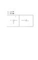
図1は、本実施形態における現実物体の3次元位置を計測する情報処理装置200の機能構成を示すブロック図である。
(Configuration example)
FIG. 1 is a block diagram illustrating a functional configuration of an
図1に示すように、本実施形態に係る情報処理装置は、撮像装置100及び撮像装置110、画像入力部1000、基準点検出部2000、対応点検出部3000、物体位置算出部4000、保持部5000によって構成される。撮像装置100及び撮像装置110によって撮像された画像に基づいて現実物体の3次元位置を計測し、3次元位置情報を出力する。
As illustrated in FIG. 1, the information processing apparatus according to the present embodiment includes an
まず、撮像装置100及び撮像装置110は、ビデオカメラであり、異なる複数の視点から、現実物体150が存在するシーンを同時に撮像する。本実施形態では、撮像装置100の焦点距離やレンズ歪み係数等のカメラ内部パラメータは予め求めておき、既知であるとする。また、撮像装置100及び撮像装置110は、撮像装置間の相対位置姿勢のカメラ外部パラメータが既知であるとする。撮像装置100及び撮像装置110の具体例として、ヘッドマウントディスプレイなどの同じ筺体に装着された2つのカメラなどが挙げられる。
First, the
画像入力部1000は、撮像装置100及び撮像装置110によって撮像された画像をコンピュータ内に取り込む。画像入力部1000は、例えば、PCに設置されたビデオキャプチャカード(画像取り込み機502)である。また、本実施形態では、取得した画像に対してレンズ歪み補正を行うことで、画像の歪みはないものとして扱う。コンピュータ内に取り込んだ画像データは、画像取り込み機502を介してRAM505上の保持部5000に出力する
基準点検出部2000は、撮像装置100及び撮像装置110によって撮像された画像間の対応を比較判定するための基準点の点群となる画像座標群を検出する。図2に示すように、基準点検出部2000は、領域抽出部2010、領域区別設定部2020、交点検出部2060、輪郭線分割部2040、平滑化部2050から構成される。
The
領域抽出部2010は、画像入力部1000によって取得された画像を保持部5000から入力し、色情報に基づいて領域抽出を行う。なお、ここでは、現実物体150の色情報を予め設定しておき、現実物体150の色情報に含まれる領域とそれ以外の領域とに分類する。領域抽出部2010は、抽出した領域を1、それ以外の領域を0とする2値画像を生成する。また、2値画像から抽出領域の輪郭線を算出し、輪郭線情報として保持部5000に出力する。このとき、例えば、輪郭線は輪郭線が囲む領域が1である場合は、時計回り、囲む領域が0である場合は、反時計回りになるように方向を決定しておく。本実施形態において輪郭線情報は、例えば、8連結の画像座標リストとして保持する。ただし、本実施形態は輪郭線情報に、方向性を持つ8連結の画像座標リストで保持することに限定されるものではなく、輪郭線と内部領域の値を適切に表現するデータであれば適用可能である。例えば、輪郭線情報として4連結の画像座標リストと輪郭線が囲む内部の値を持つ変数を対応付けて保持してもよい。
The
領域区別設定部2020は、領域抽出部2010にて抽出した抽出領域にラベル付けを行うことで領域を区別する。ここでは、領域の面積の大きい順にラベルを付け、閾値以下の面積の領域はノイズとして除去する。ノイズ除去を行い、残った領域の輪郭線情報とラベル情報を対応付けて保持部5000へ出力する。
The region
輪郭線取得部2030は、抽出領域の輪郭線を取得する。
The contour
輪郭線分割部2040は、保持部5000から、輪郭線情報を取得し、入力された対象物体の外形の特徴を残して、輪郭線を分割する。
The
本実施形態においては、分割の処理は再帰的に実施するため、最初の分割が終わった時点で、分割点により分割された輪郭線の距離の長さから、分割した輪郭線が分割点を結ぶ真っすぐ線分に近似されたか否かを判定する。線分に近似できない輪郭をさらに分割する。輪郭線分割部2040は、最終的に得られた輪郭線の分割点の画像座標を保持部5000に出力する。輪郭線分割の再帰的処理の詳細については後述する。
In this embodiment, since the division process is performed recursively, the divided contour lines connect the division points from the length of the distance of the contour lines divided by the division points when the first division is completed. It is determined whether or not it is approximated to a straight line segment. A contour that cannot be approximated to a line segment is further divided. The
なお、本実施形態においては輪郭線の分割に再帰的な分割アルゴリズムを利用することに限定されるものではなく、最終的に対象物体の特徴を残して平滑化できる輪郭線分割アルゴリズムであれば適用可能である。例えば、輪郭線の曲率が閾値よりも大きい場合は分割点を追加するという方法でも適用可能である。 Note that the present embodiment is not limited to the use of a recursive division algorithm for dividing the outline, and can be applied to any outline division algorithm that can be smoothed while leaving the features of the target object finally. Is possible. For example, when the curvature of the contour line is larger than a threshold value, a method of adding a dividing point is also applicable.
平滑化部2050は、輪郭線分割部2040で出力された分割点を線分で結ぶことで、元の輪郭線を平滑化した平滑化輪郭線の輪郭線情報を生成する。平滑化した輪郭線情報は保持部5000に出力され、輪郭線取得部2030で取得された元の情報と置き換えられる。以降、置き換えられた輪郭線情報が取得された輪郭線情報であるとする。
The
交点検出部2060は、検出処理の前に、撮像装置100と撮像装置110によって撮像した各画像に走査線を予め設定しておく。この走査線は、各画像間で、現実空間における同じ位置を通過しているとみなした線である。
The
走査線を設定する例として、撮像装置100と撮像装置110との相対位置があらかじめ分かっていれば、画像上においてどの位置を通過しているかを想定して設定することができる。例えば、ヘッドマウントディスプレイの同じ高さの左右に水平で配置されていれば、撮像装置100で撮像された画像と撮像装置110で撮像された画像との各々の同じ高さに水平線を引けばよい。これは、後述するエピポーラ線の一種に含まれる。
As an example of setting a scanning line, if the relative position between the
他にも、走査線を設定する例として、撮像装置100と撮像装置110とが撮像する現実空間に視覚レーザーをライン状に照射すれば、撮像装置100と撮像装置110との両方で撮像されたレーザーラインの延長線を走査線として用いることができる。
In addition, as an example of setting a scanning line, if a visual laser is irradiated in a line shape in a real space captured by the
本実施形態では、走査線として、一般的にエピポーラ線と呼ばれる線を設定する。エピポーラ線について簡単に説明する。2台の撮像装置の視点をそれぞれC,C’とし、3次元空間中のある点をPとすると、このC,C’,Pの3点は空間中に一つの平面Σを定義できる。この平面をエピポーラ平面と呼び、エピポーラ平面と画像面が交差してできる直線をエピポーラ線と呼ぶ。 In this embodiment, a line generally called an epipolar line is set as the scanning line. The epipolar line will be briefly described. If the viewpoints of the two imaging devices are C and C ′, respectively, and a certain point in the three-dimensional space is P, the three points C, C ′, and P can define one plane Σ in the space. This plane is called an epipolar plane, and a straight line formed by the intersection of the epipolar plane and the image plane is called an epipolar line.
本実施形態では、撮像装置100の画像の画像中心を通り、垂直方向に10ピクセル単位で区切る点群Pnと、撮像装置100の視点Cと撮像装置110の視点C’とからエピポーラ平面群Lnを算出する。そして、撮像装置100と撮像装置110の各投影面におけるエピポーラ線群En(必要に応じて走査線300と言い換える)を配置する。
In the present embodiment, the epipolar plane group Ln is formed from the point group Pn that passes through the image center of the image of the
このように、あらかじめエピポーラ線群を用意しておくことで、左右の画像で抽出領域の輪郭線マッチングを高速に行うことができる。 In this way, by preparing the epipolar line group in advance, it is possible to perform contour matching of the extraction region at high speed between the left and right images.
そして、交点検出部2060は、平滑化部2050で算出した輪郭線情報と走査線情報300を入力して、平滑化した輪郭線と走査線の交点を検出する。さらに、交点の近傍における属性を記録する。この属性は、交点が、走査線の走査方向に対して、抽出領域の左側なのか、右側なのかを判定するための特徴である。図8に示すように、走査線上を左から右に探索して、交点上で抽出領域が0から1に変化する場合には正の符号を与え、1から0に変化する場合には負の符号を与える。
Then, the
本実施形態では、例えば輪郭線の方向によって判断する。すなわち、交点における輪郭線の次のピクセルの方向が上、右上、右、左上のいずれかを指している場合は、抽出領域の左側と判断する。逆に、交点における輪郭線の次のピクセルの方向が下、左下、左、右下のいずれかを指している場合は、抽出領域の右側と判断する。 In the present embodiment, the determination is made based on the direction of the contour line, for example. That is, when the direction of the pixel next to the contour line at the intersection point indicates any of the upper, upper right, right, or upper left, it is determined that the pixel is on the left side of the extraction region. Conversely, if the direction of the pixel next to the contour line at the intersection point indicates any of the lower, lower left, left, and lower right, it is determined as the right side of the extraction region.
交点を領域の左側と判断した場合は、属性に1を設定し、領域の右側と判断した場合は属性に−1を設定する。この属性は、対応点検出部3000の対応付けに利用する。
If it is determined that the intersection is on the left side of the area, 1 is set in the attribute. If it is determined that the intersection is on the right side of the area, -1 is set in the attribute. This attribute is used for association by the corresponding
得られた交点の画像座標と属性は、交点情報として保持部5000へ出力する。
The obtained image coordinates and attributes of the intersection are output to the
保持部5000は、以下の管理する情報のデータを保持する。
・カメラ映像(撮像部100、110から得られた映像)
・輪郭線情報(ラベルと画像座標の連結リストを要素として持つ)
・輪郭線の分割点情報(輪郭線平滑化のために生成した分割点の画像座標リスト)
・交点情報(輪郭線とエピポーラ線の交点を表わす画像座標のリストと、交点の領域における左側か右側かを判断する属性リストを要素として持つ)
・対応点情報(対応付け部3000の処理によって出力される左右画像の交点の対応情報)
保持部5000は、管理する情報を対応点検出部3000に出力する。
なお、本実施形態においては、保持部5000に上記のデータ種を保存することに限定されるものではなく、物体配置算出部4000の処理に流用可能な、対象物体の特徴を残した輪郭線の分割点情報を含んでいればよい。
The
・ Camera images (images obtained from the
・ Outline information (has a linked list of labels and image coordinates as elements)
・ Outline division point information (image coordinate list of division points generated for contour smoothing)
・ Intersection information (has a list of image coordinates representing the intersection of the contour line and epipolar line, and an attribute list that determines whether it is the left or right side of the intersection area)
Corresponding point information (corresponding information of intersections of left and right images output by the processing of the association unit 3000)
The
Note that, in the present embodiment, the data type is not limited to being stored in the
対応点検出部3000は、基準点検出部2000で検出された交点情報に基づいて、撮像装置100と撮像装置110とで撮像した画像間の対応関係となる対応点を検出する。
The corresponding
図3は、対応点検出部3000の構成を示すブロック図である。対応点検出部3000は、属性判定部3010、第1の一致度算出部3020、第1の対応点判定部3030、領域対応付け部3040、第2の対応点判定部3050、走査線分割部3060、第3の対応点判定部3080から構成される。
FIG. 3 is a block diagram illustrating a configuration of the corresponding
属性判定部3010は、保持部5000から交点情報と輪郭線情報を入力して、走査線300上における交点の属性をリスト化する。具体的には、走査線上の交点が、走査線の走査方向に対して、抽出領域の左側なのか、右側なのかを判定した属性を走査線ごとにリスト化する。
The
第1の一致度算出部3020は、第1の撮像装置100で撮像した画像における交点属性リストと、第2の撮像装置110で撮像した画像における交点属性リストの比較を行い、一致度Pを算出する。算出した一致度Pを第1の対応点判定部3030へ出力する。
The first matching
第1の対応点判定部3030は、第1の一致度算出部3020から交点属性リストの一致度Pを入力し、交点属性リストの一致度に基づいて、画像間で対応関係となる対応点の判定を行う。対応点の画像座標の組を対応点情報として領域対応付け部3040へ出力する。
The first corresponding
領域対応付け部3040は、第1の対応点判定部3030から対応点情報を入力する。対応点が存在する平滑化された輪郭線と、その輪郭線が境界となる抽出領域のラベルとを対応付け、抽出領域のラベルを平滑化された輪郭線の対応情報として第2の対応点判定部3050へ出力する。
The
第2の対応点判定部3050は、領域対応付け部3040で判定された領域の対応付けから、第1の対応点判定部3030で判定された対応点を通過した輪郭線が通過する他の交点も同様に対応点とする。新たな対応点情報を走査線分割部3060へ出力する。
The second corresponding
走査線分割部3060は、第2の対応点判定部3050から対応点情報を入力し、対応点に基づいて交点属性リストを分割する。具体的には、対応点の位置で走査線を分割した分割走査線を用意する。交点属性リスト内で、対応点の位置にあった属性以外の属性は、分割走査線の何れかの属性となる。分割した交点属性リストを第3の第2の一致度算出部3070へ出力する。
The scanning
第2の一致度算出部3070は、第1の撮像装置100で撮像した画像における分割した交点属性リストと、第2の撮像装置110で撮像した画像における分割した交点属性リストの比較を行い、一致度Qを算出する。算出した一致度Qを第3の対応点判定部3080へ出力する。
The second degree-of-
第3の対応点判定部3080は、走査線分割部3060から分割した交点属性リストを入力する。分割した交点属性リストの一致度Qに基づいて、対応点を判定し、対応点情報を保持部5000に出力する。
The third corresponding
物体配置算出部4000は、交点情報と対応点情報に基づいて、対象物体の3次元配置を算出する。ここでの3次元配置とは、3次元の位置、姿勢、もしくは位置姿勢を示す。
The object
図16は、物体配置算出部4000のブロック図である。物体配置算出部4000は、交点奥行き算出部4010、輪郭線奥行き補間部4020、3次元配置生成部4030から構成される。
FIG. 16 is a block diagram of the object
交点奥行き算出部4010は、保持部5000から交点情報と対応点情報を入力し、2つの画像において対応付けられた交点の撮像装置に対する奥行きを算出する。算出した交点の奥行き値は、撮像装置100、撮像装置110の夫々の画像における交点情報にそれぞれ対応付ける。検出した対応点情報と奥行き値を輪郭線奥行き補間部4020に出力する。
The intersection
輪郭線奥行き補間部4020は、輪郭線上に算出された複数の交点の奥行き値から線形補間することにより輪郭線のピクセル全体に奥行き値設定する。奥行き値付きの輪郭線情報は、3次元配置生成部4030に出力する。
The contour line
3次元配置生成部4030は、保持部5000の輪郭線分割情報を入力し、分割点の画像座標と、分割点における輪郭線の奥行き値とから、対象物体の3次元配置情報を生成する。
The three-dimensional
従来は、3次元配置生成部4030において、対象物体の形状の特徴を残した頂点情報を算出する必要がある。しかし、輪郭線分割部2040において、平滑化処理のために、あらかじめ生成した分割点を流用することにより、頂点情報算出処理の時間を省略することができる。
Conventionally, it is necessary for the three-dimensional
(基準点検出フロー)
次に、基準点検出部2000の処理の詳細について述べる。図4に、基準点検出部2000の処理の流れを示す。
(Reference point detection flow)
Next, details of the processing of the reference
ステップS2011では、予め登録しておいた、被写体となる物体色情報を入力する。 In step S2011, object color information as a subject registered in advance is input.
ステップS2012では、撮像装置100、及び撮像装置110によって撮像した画像の各画素の色と、物体色情報が示す色とを比較する。
In step S2012, the color of each pixel of the image captured by the
ステップS2013では、画像の各画素について色情報と被写体の色情報とを比較し、入力した物体色情報に含まれるならば1、それ以外なら0とする。 In step S2013, the color information for each pixel of the image is compared with the color information of the subject, and is set to 1 if included in the input object color information, and set to 0 otherwise.
ステップS2014では、色情報の比較結果に基づいて2値画像を生成する。ここでは、入力した物体色情報に含まれるならば白、それ以外の領域を黒とする。 In step S2014, a binary image is generated based on the comparison result of the color information. Here, if it is included in the input object color information, it is white, and the other area is black.
ステップS2015では、2値画像のラベリングを行う。 In step S2015, the binary image is labeled.
ステップS2016では、ラベリング後の画像から、設定した閾値よりも面積の小さい領域をノイズとして除去する。すなわち、ノイズと見なした領域内の0と1とを(白と黒とを)反転させる。 In step S2016, a region having an area smaller than the set threshold is removed as noise from the labeled image. That is, 0 and 1 in a region regarded as noise are inverted (white and black).
上記の方法では、物体領域を検出するために色情報によって領域抽出している。そのため、影になる部分や、同系色の領域がある場合には、ステップS2016で行うノイズ処理では、誤検出やノイズを完全に取り除くことができない。図5は、そのようなノイズを含んだ領域抽出結果の2値画像を示す。 In the above method, an area is extracted based on color information in order to detect an object area. For this reason, when there is a shadowed part or a similar color area, the noise processing performed in step S2016 cannot completely remove false detections and noise. FIG. 5 shows a binary image as a region extraction result including such noise.
領域抽出で用いられる色情報は、多次元色空間における座標値として記述できる。例えば、RGB、YIQ、YCbCr、YUV、HSV、Luv、Labなど様々な種類がある。対象とする被写体の色彩特性に合わせて適当なものを任意に用いてよい。また、領域を分割する方法は上記に限るものではなく、色情報を用いる何れの方法で行ってもよい。 Color information used in region extraction can be described as coordinate values in a multidimensional color space. For example, there are various types such as RGB, YIQ, YCbCr, YUV, HSV, Luv, and Lab. Any appropriate one may be used according to the color characteristics of the subject. Further, the method of dividing the region is not limited to the above, and any method using color information may be used.
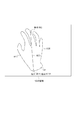
ステップS2017では、輪郭線分割部2040、および平滑化部2050が抽出された領域の輪郭線を平滑化する。平滑化の処理の詳細は後述する。
In step S2017, the contour
ステップS2018では、交点検出部2060が、平滑化された輪郭線と走査線との交点を検出し、画像座標を求める。図6に抽出領域の2値画像に走査線300を重ねて表示した図を示す。本実施形態では、走査線300に前述したエピポーラ線Enを用いるため、撮像装置100で検出された対象物体の画像座標は、撮像装置110で撮像された画像の走査線上で検出されるという性質を持つ。一方で、撮像装置110で検出された対象物体の画像座標は、撮像装置100で撮像された画像の走査線上で検出される。
In step S2018, the
走査線300と平滑化された輪郭線が交わる点を交点情報として保持部5000に保存する。ここで保存された交点情報は、対応点検出部3000の処理によって撮像装置100の画像の交点と撮像装置110の画像における交点が対応付けられる。
A point where the scanning line 300 and the smoothed outline intersect is stored in the
さらに、交点検出部2060は、交点の画像座標における輪郭線の次のピクセルへの方向を参照し、抽出領域が交点において、右側か左側か(走査線の始点側か終点側か)を判断して属性に保存する。この属性は交点座標と対応付けられて交点情報の一要素として記録される。
Further, the
ステップS2019では、交点情報保持手段2040が交点情報と抽出領域の輪郭線情報を対応点検出部3000へ出力する。
In step S2019, the intersection
(輪郭線の分割処理の詳細フロー)
ここで、ステップS2017における輪郭線を分割することで、平滑化を行う処理の詳細を図13に示すフローチャートと図20、図21に示す模式図を用いて説明する。
(Detailed flow of outline division processing)
Here, the details of the process of performing the smoothing by dividing the contour line in step S2017 will be described with reference to the flowchart shown in FIG. 13 and the schematic diagrams shown in FIGS.
ステップS1301では、端点設定を行う。具体的には、輪郭線分割部2040が、輪郭線上にある画素群の画像座標の連結リストを参照し、リストの始点1801A(第1の点)と終点1801B(第2の点)との2つの端点を設定する。そして、中点設定を行う。具体的には、2つの端点の中間となる中点C1802(第3の点)を決定する(図20参照)。例えば、輪郭線の連結リストが200ピクセルで構成されている場合は、100ピクセル目の画像座標を中点C1802と設定する。
In step S1301, end point setting is performed. Specifically, the
ステップS1302では、輪郭線分割部2040が、始点1801A、終点1801B、分割した中点C1802の画像座標を保持部5000の輪郭線の分割点情報として記録する。なお、重複する分割点が存在する場合には記録しない。
In step S1302, the
ステップS1303では、輪郭線分割部2040が、始点1801Aと中点C1802との直線距離L1803と、始点1801Aと中点C1802の2点を通過する輪郭線1804(例えば、元の輪郭線の左半分)の画像座標系における長さNを算出する。画像座標系におけるピクセルに相当する長さNは、上下左右に隣接するピクセル間の長さを1とし、8連結リストで斜め方向に配置された長さはルート2として算出する。ただし、本実施形態では、前述の輪郭線分割方法に限定されるものではなく、輪郭線の特徴的な形状を保ちながら平滑化できる算出方法であれば対応可能である。
In step S1303, the
ステップS1304では、輪郭線分割部2040が、ステップS1303で算出した輪郭線の長さNが予め設定された所定値以上であるかどうか判定する。本実施形態においては、例えば4ピクセルを設定する。輪郭線の長さNが4ピクセル以上であれば、ステップS1305に移行し、4ピクセル未満の場合は、ステップS1307に処理を移す。4ピクセル未満のときに分割を終了して次の輪郭線に処理を移すのは、輪郭線を細かくした線分群を生成しても平滑化の効果が期待できないためである。
In step S1304, the
ステップS1305では、輪郭線分割部2040が、Nの二乗とLの二乗との差を算出し、予め設定された所定値以上であるかどうかを判定する。本実施形態においては、例えば50を設定する。本実施形態では、直線の判定にNとLを用いた式を用いることに限定されるものではなく、輪郭線の特徴的な形状を残して平滑化できる輪郭線分割方法であれば適用可能である。
In step S1305, the
所定値を超える場合は、まだ直線に近似できないと判断してステップS1306に処理を移す。例えば、図20において、始点1801Aと中点C1802における直線距離Lと輪郭線の区間1804の長さNを算出する。この事例では、所定値を超えるため、ステップS1306に処理を移す。
If it exceeds the predetermined value, it is determined that it cannot be approximated to a straight line yet, and the process proceeds to step S1306. For example, in FIG. 20, the straight line distance L between the start point 1801A and the midpoint C1802 and the length N of the
始点Aを変えずに分割点である中点Cを終点Bに置き換えるため、始点Aから始まる線分が直線に近似できるまで輪郭線を細分化する。所定値を下回るまで再帰的に輪郭線が分割された場合は、次の輪郭線の区間に処理を移すため、ステップS1307に移行する。 In order to replace the middle point C, which is a division point, without changing the starting point A, the end point B is subdivided until the line segment starting from the starting point A can be approximated to a straight line. When the contour line is recursively divided until it falls below the predetermined value, the process proceeds to step S1307 in order to shift the process to the next contour line section.
ステップS1306では、中点C1802を終点1801Bに置き換えて、ステップS1301に処理を移す。すなわち、処理する点を入れ替て再帰的に処理を実行する。次の処理では、図21(A)の中点1821を分割点とする。
In step S1306, the middle point C1802 is replaced with the end point 1801B, and the process proceeds to step S1301. That is, the process is recursively executed by changing the points to be processed. In the next process, the
ステップS1307では、輪郭線分割部2040が現在設定されている始点1801Aと終点1801Bの間の輪郭線が直線に近似されたと判定し、始点1801Aと終点1801Bの画像座標を保持部5000の輪郭線の分割点情報として記録する。さらに、輪郭線分割部2040が、保持部5000を参照し、現在処理している輪郭線のうち、処理が完了していない輪郭線の区間がないかどうかを判定する。すべての輪郭線の区間が処理されており、輪郭線の分割点情報に分割点が記録されている場合は処理を終了する。輪郭線の区間のなかで輪郭線が直線に近似できていない場合は、ステップS1308に処理を移す。
In step S1307, the
ステップS1308では、輪郭線分割部2040が、現在選択されている輪郭線の区間以外で分割処理が完了していない輪郭線の区間を選択し、現状の始点Aと終点Bを選択した輪郭線の区間の始点と終点に置き換える。
In step S1308, the
ステップS1306では、始点を変えずに再帰的に分割処理を実行した。一方でステップS1308では、始点と終点をまだ処理が終了していない区間に移して処理を継続し、輪郭線の全区間において、分割処理ができるようにする。 In step S1306, the division process is recursively executed without changing the starting point. On the other hand, in step S1308, the start point and the end point are moved to a section where the processing has not been completed, and the processing is continued so that the division processing can be performed in all the sections of the contour line.
このように、設定された点群のうち輪郭線上で隣り合う点を互いに結ぶ線分群を生成することで、平滑化輪郭線を生成した。すなわち、輪郭線上の2点の距離が、所定値未満になるまで、繰り返し分割し、所定値未満の長さの真っ直ぐの線分群に置き換えを行う。 Thus, the smoothing outline was produced | generated by producing | generating the line segment group which connects the points which adjoin on the outline among the set point groups. That is, the division is repeated until the distance between the two points on the contour line is less than a predetermined value, and a straight line group having a length less than the predetermined value is replaced.
ここで本実施形態において、撮像部100から図20の映像が出力された時の事例を示す。輪郭線を分割する処理を初めて、ステップS1305の判定が所定値を超えなくなるまで輪郭線を細分化したときの分割点の配置例を図21の(A)から(D)の模式図に示している。図のように、始点1801Aを始点とする輪郭線を再帰的に求めている。このように平滑化処理を進めると、最終的に図14のような結果となる。
Here, in this embodiment, an example when the image of FIG. 20 is output from the
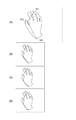
(ノイズ軽減)
次に、この処理により、カメラノイズや照明ノイズ等のノイズを軽減する効果を説明する。図17はノイズがない状態における撮像部100と撮像部110の画像において、対象物体の輪郭線付近を抜き出した図を示している。図18はカメラノイズや照明ノイズ等で交点と対応点との距離が変化する現象を示す模式図である。図19は、平滑化をすることでノイズの影響を軽減する効果があることを説明する模式図である。
(Noise reduction)
Next, the effect of reducing noise such as camera noise and illumination noise by this processing will be described. FIG. 17 is a diagram in which the vicinity of the contour line of the target object is extracted from the images of the
図17(A)は左に配置された撮像部100の画像、図17(B)は右に配置された撮像部110の画像を示す。図17の点線で表示されている線1702Lと1702Rが対象物体150の理想の輪郭線を示している。図17では、ステップS2013で領域抽出部2010が抽出した領域に模様を付けて示した。すなわち、模様が付いているピクセルが1、ついていないピクセルが0を表わしている。さらに、ステップS2015でラベリングにより輪郭線を求めた結果を輪郭線1703Lと1703Rに示している。
17A shows an image of the
この状態で、ステップS2018により走査線と抽出領域(輪郭線)との交点を求めた結果が図17の太枠で表示した交点1701Lと1701Rとする。さらに、図17(A)の交点1701Lを図17(B)の画像の同じ位置に投影した点を対応点1705として提示している。すなわち、ノイズのない理想的な状態では、交点1701Rと対応点1705(交点1701L)は2ピクセル分の距離があることを示している。対象物体と撮像部が静止していれば、理想的にはこの2ピクセルの距離から変化しない。 In this state, the intersections 1701L and 1701R displayed by the thick frame in FIG. 17 are obtained by obtaining the intersections between the scanning line and the extraction region (contour line) in step S2018. Further, a point obtained by projecting the intersection 1701L of FIG. 17A on the same position of the image of FIG. 17B is presented as a corresponding point 1705. That is, in an ideal state without noise, the intersection 1701R and the corresponding point 1705 (intersection 1701L) have a distance of two pixels. If the target object and the imaging unit are stationary, ideally, the distance from the two pixels does not change.
しかし、実際には、カメラノイズや照明ノイズ等でこの距離が変化してしまう。すなわち、対象物体の理想的な輪郭線に対して、図18(B)のように、正常に領域を検出できず、輪郭線の形状が理想とは大幅に異なっている。このときに抽出領域の輪郭線と走査線との交点は理想的な状態からずれが生じる。その結果、交点1701Rと対応点1705(交点1701L)の距離が3ピクセルとして出力される。すなわち、距離が変化したため、理想的な奥行き値に対して誤差が生じてしまう。さらに図18(A)と図18(B)の次のフレームにおける処理結果を示しているのが図18(C)と図18(D)である。次のフレームもノイズの影響により、領域が正しく抽出されず、さらに前のフレームとも形状が異なっている。図18(D)においては、交点1701Rと対応点1705の距離は1となる。すなわち、(A)、(B)と(C)、(D)の2フレーム間で距離が大幅に異なる結果となるため、奥行き値に関しても安定しない。 However, in practice, this distance changes due to camera noise, illumination noise, and the like. That is, as shown in FIG. 18B, the region cannot be normally detected with respect to the ideal contour line of the target object, and the contour shape is significantly different from the ideal. At this time, the intersection between the contour line of the extraction region and the scanning line deviates from an ideal state. As a result, the distance between the intersection 1701R and the corresponding point 1705 (intersection 1701L) is output as 3 pixels. That is, since the distance has changed, an error occurs with respect to the ideal depth value. Further, FIG. 18C and FIG. 18D show the processing results in the next frame of FIG. 18A and FIG. 18B. In the next frame, the region is not correctly extracted due to the influence of noise, and the shape is different from the previous frame. In FIG. 18D, the distance between the intersection 1701R and the corresponding point 1705 is 1. That is, since the distance is significantly different between the two frames (A), (B) and (C), (D), the depth value is not stable.
一方で、本実施形態で示す平滑化を図18(A)〜(D)に適用した図が図19(A)〜(D)である。ノイズにより対象物体の理想的な輪郭線に対して、算出された輪郭線が異なっていることは変らない。しかし、平滑化によって、図19(A)、(B)と図19(C)、(D)の交点1701Rと対応点1705との距離は両フレームとも2であり、安定化の効果があることがわかる。 On the other hand, FIGS. 19A to 19D are diagrams in which the smoothing shown in the present embodiment is applied to FIGS. It remains unchanged that the calculated contour line differs from the ideal contour line of the target object due to noise. However, due to the smoothing, the distance between the intersection 1701R and the corresponding point 1705 in FIGS. 19A and 19B and FIGS. 19C and 19D is 2 in both frames, which has a stabilizing effect. I understand.
(対応付け処理フロー)
次に、対応点検出部3000の処理の詳細について述べる。図7に、対応点検出部3000の処理の流れを示す。
(Association process flow)
Next, details of the processing of the corresponding
ステップS3011では、属性判定部3010が、保持部5000から、交点情報と輪郭線情報を入力する。
In step S <b> 3011, the
ステップS3013では、属性判定部3010が、交点情報と輪郭線情報から、走査線上における交点近傍の属性をリスト化する。図9には、交点近傍の属性を抽出領域に表示した図を示す。ここで、図9において、○は正の符号を表し、△は負の符号を表す。
In step S3013, the
ステップS3014では、第1の一致度算出部3020が、撮像装置100及び撮像装置110で撮像した夫々の画像での属性リストの一致度Pを算出する。属性リストの属性を左側から順にスキャンし、属性の総数をそれぞれS100、S110とし、一致した属性の総数をCとすると、一致度Pは、次のように求める。
In step S3014, the first matching
P=C/S110(S100<=S110のとき)
P=C/S100(S110<S100)
一致度の算出方法は、求めた属性に基づいて算出するものであれば、これに限るものではない。
P = C / S 110 (when S 100 <= S 110 )
P = C / S 100 (S 110 <S 100 )
The degree of coincidence calculation method is not limited to this as long as it is calculated based on the obtained attribute.
図10は、抽出領域の輪郭線と走査線の交点を示した図から、走査線Jを取り出した模式図である。 FIG. 10 is a schematic diagram in which the scanning line J is extracted from the diagram showing the intersection point of the contour line of the extraction region and the scanning line.
ステップS3015では、第1の判定部3030が、一致度Pを読み出し、閾値T以上の一致度であれば、画像間で対応関係にある対応点であると判定する。例えば、図10における走査線J以外(例えば走査線Jの2、3本、上方にある走査線)での属性リストが一致した場合、その交点は対応点であると判定できる。
In step S <b> 3015, the
ステップS3016では、領域対応判定部3040が、対応点であると判定された交点を通過する輪郭線を輪郭とする抽出領域のラベルを、撮像装置100及び撮像装置110で撮像した夫々の画像で対応付ける。
In step S3016, the region
ステップS3017では、第2の対応点判定部3050が、ステップS3016で対応付けられた領域の輪郭線と走査線との交点で、かつまだ対応点と判定されていない交点を対応点として判定する。すなわち、S3015で対応が取れた交点を通過する輪郭線上の他の交点も、同様に対応がとれているものとみなし、対応点として判定する。例えば、図10のC1、C2、及びC1’、C2’は、対応付けできると判定された対応点である。これは、S3015で得た対応点を通過する、S3016で対応すると判定された領域の輪郭線上に存在するため、対応点として判定することができる。
In step S3017, the second corresponding
ステップS3018では、走査線分割部3060が、走査線上の交点近傍の属性をリスト化した交点属性リストを、ステップS3017で対応付けた対応点の位置で分割する。例えば、図10における、走査線J上の交点近傍の属性をリスト化した交点属性リストを、対応点C1及びC2の位置で分割する。これにより撮像装置100で撮像した画像においてJ1、J2、J3、撮像装置100で撮像した画像においてJ1’、J2’、J3’のように夫々3つの分割走査線に分割できる。
In step S3018, the scanning
さらにステップS3018では、走査線分割部3060が、ステップS3017で、分割走査線ごとに、分割した交点属性リストの夫々の一致度を算出する。例えば、図10におけるJ1とJ1’、J2とJ2’、J3とJ3’、の一致度を、第1の一致度算出部3020と同様の処理を行うことで算出する。
In step S3018, the scanning
ステップS3019では、第3の対応点判定部3080が、ステップS3018で算出した一致度に基づいて、まだ対応点であると判定されていない交点を新たな対応点として判定する。図11は、走査線上で対応点を求める方法を説明するための模式図である。図11では、J1とJ1’の部分の交点が一致するため、対応点として判定する。
In step S3019, the third corresponding
ステップS3010では、第3の対応点判定部3080が、撮像装置100で撮像された画像における対応点Cn(n=1,2,,,N)と、撮像装置110で撮像された画像における対応点C’n(n=1,2,,,N)との画像座標の組を対応点情報とする。対応点情報は、保持部5000へ出力する。ここでNは、対応点の組の総数である。
In step S3010, the third corresponding
(3次元配置算出フロー)
次に、物体配置算出部4000の処理の詳細について説明する。図12は、対象物体の3次元配置を算出するフローを示す図である。
(Three-dimensional layout calculation flow)
Next, details of the processing of the object
ステップS4010では、交点奥行き算出部4010が、保持部5000から対応点情報を取得して3次元配置を計測する。本実施形態では、エピポーラ線を利用して3次元配置を算出する。
In step S4010, the intersection
エピポーラ線は、エピポーラ方程式より求めることができる。 The epipolar line can be obtained from the epipolar equation.
エピポーラ方程式について説明する。撮像装置の位置を3×1ベクトルT=(Tx,Ty,Tz)、回転を3×3行列Rで表す。いま行列Eを次式のように置く。 The epipolar equation will be described. The position of the imaging device is represented by a 3 × 1 vector T = (Tx, Ty, Tz), and the rotation is represented by a 3 × 3 matrix R. Now, the matrix E is set as follows:
![]()
![]()
ここで、[T]xは、次式のように表す。 Here, [T] x is expressed as follows.

2台の撮像装置で撮像した画像上の対応点を同次座標でそれぞれx=[x,y,1]T、x’=[x’,y’,1]Tと表すと、エピポーラ方程式は、次式のように表せる。 When the corresponding points on the images picked up by the two image pickup devices are expressed in homogeneous coordinates as x = [x, y, 1] T and x ′ = [x ′, y ′, 1] T, respectively, the epipolar equation is Can be expressed as:
![]()
![]()
したがって、2つの画像上で対応する点xとx’の関係を表す式となり、エピポーラ線を求めることができる。 Therefore, the equation represents the relationship between the corresponding points x and x 'on the two images, and an epipolar line can be obtained.
このようにエピポーラ線は、2台の撮像装置間の相対位置姿勢から求めることが可能である。また、2台の撮像装置間の相対位置姿勢は、カメラキャリブレーションの技術により求めることができる。カメラキャリブレーションについての詳細な説明は省略する。 Thus, the epipolar line can be obtained from the relative position and orientation between the two imaging devices. In addition, the relative position and orientation between the two imaging devices can be obtained by a camera calibration technique. A detailed description of camera calibration is omitted.
次に、光軸の方向と視点の高さをそろえていない2台の撮像装置を用いた3次元配置算出方法について述べる。 Next, a three-dimensional arrangement calculation method using two imaging devices that do not align the optical axis direction and the viewpoint height will be described.
焦点距離や主点位置などの内部パラメータは既知であり、また撮像装置の相対位置姿勢の外部パラメータも既知であるとする。撮像装置の内部パラメータと外部パラメータを合成した行列Pを次式のように表すことができる。 It is assumed that internal parameters such as focal length and principal point position are known, and external parameters of the relative position and orientation of the imaging device are also known. A matrix P obtained by combining the internal parameters and the external parameters of the imaging device can be expressed as the following equation.
撮像装置100で撮像された画像から検出された対応点の座標をCn=[un,vn]とする。求める3次元空間の点の位置をX=[Xn,Yn,Zn]と表すと、次式のように表せる。
The coordinates of the corresponding points detected from the image captured by the
λは、式5の第3行目より決まる実数である。式3を展開してX、Y、Zに関してまとめると、次式のように表せる。
λ is a real number determined from the third line of Equation 5. When
本実施形態では、撮像装置の内部パラメータと外部パラメータは、既知であるのでPは既知のパラメータである。ひとつの撮像装置で撮像した画像から2つの拘束式が得られる。撮像装置110の撮像装置のパラメータをP’とし、撮像された画像から検出された対応点の座標をC’n=[un’,vn’]とすると、次のように4つの拘束式が得られる。
In this embodiment, since the internal parameter and the external parameter of the imaging apparatus are known, P is a known parameter. Two constraint formulas can be obtained from an image captured by one imaging device. Assuming that the parameter of the imaging device of the
式5は、未知数3に対して4つの拘束式が得られる。式5を次式のようにおくと、 In Expression 5, four constraint expressions are obtained for the unknown 3. If Formula 5 is put into the following formula,
![]()
![]()
Xの最小二乗階は、次式のように求めることができる。 The least square floor of X can be obtained as follows.
![]()
![]()
これを、すべての対応点に対して計算することで、物体配置算出部4000は、物体領域の輪郭線上の点である対応点の3次元座標を計測することができる。交点奥行き算出部4010は、撮像装置100を基準にして求めた物体領域の3次元座標のZ座標(奥行き値)を輪郭線上の奥行き補間部4020に出力する。
By calculating this for all corresponding points, the object
ステップS4020では、輪郭線上の奥行き補間部4020が、ステップS4010で得た奥行き値を保持部5000の輪郭線情報の画像座標と対応点情報とに基づいて、輪郭線に沿って線形補間する。
In step S4020, the
ステップS4030では、線形補間された輪郭線から、仮想物体のポリゴンを作成する。 In step S4030, a polygon of a virtual object is created from the linearly interpolated contour line.
ステップS4040では、撮像装置100および撮像装置110で撮像された各画像に、作成されたポリゴンを仮想画像として重畳描画し、重畳された画像を不図示の表示装置へと出力する。
In step S4040, the created polygon is superimposed and drawn as a virtual image on each image captured by the
(MR技術への適用)
本実施形態に係る情報処理装置を、MRにおける撮像装置を備えるヘッドマウンテッドディスプレイやハンドヘルドディスプレイに適用すれば、現実物体と仮想物体との3次元配置情報を比較し、画像や仮想物体を手前に描画することができる。
(Application to MR technology)
When the information processing apparatus according to the present embodiment is applied to a head-mounted display or a hand-held display including an imaging apparatus in MR, the three-dimensional arrangement information of the real object and the virtual object is compared, and the image or the virtual object is brought forward. Can be drawn.
ここで、ヘッドマウンテッドディスプレイとは、頭部に装着するディスプレイのことであり、また、ハンドヘルドディスプレイとは、手持ちのディスプレイである。これらは、複合現実感システムを構築する際に一般的によく利用される。なお、ヘッドマウンテッドディスプレイやハンドヘルドディスプレイに撮像装置を装着する場合には、ディスプレイの光軸と、撮像装置の光軸を一致させることが望ましい。 Here, the head mounted display is a display worn on the head, and the handheld display is a handheld display. These are commonly used when constructing a mixed reality system. In addition, when mounting an imaging device on a head-mounted display or a hand-held display, it is desirable to match the optical axis of the display with the optical axis of the imaging device.
このようにヘッドマウントディスプレイ等の表示装置と組み合わせて手などの物体領域の奥行きを計測することで、現実物体と仮想物体の前後関係を正しく表現することができ、正しく知覚することができる。 Thus, by measuring the depth of an object region such as a hand in combination with a display device such as a head-mounted display, the front-rear relationship between the real object and the virtual object can be correctly expressed and can be perceived correctly.
また、手などの現実物体の3次元配置情報を取得できることにより、現実物体と3Dモデルとの干渉判定が実施可能となる。すなわち、製品設計において、試作品ができる前に工具等の現実物体と3DCADモデルの干渉判定の検証ができるようになり、試作コストを低減できる可能性がある。また、サイバーグローブのような入力装置なしで3Dモデルに直接手で触れて操作することができるようになる。 In addition, since it is possible to acquire three-dimensional arrangement information of a real object such as a hand, it is possible to perform interference determination between the real object and the 3D model. That is, in product design, it becomes possible to verify the interference judgment between a real object such as a tool and a 3D CAD model before a prototype is made, and there is a possibility that the cost of trial production can be reduced. In addition, the 3D model can be directly touched and operated without an input device such as a cyber glove.
上記で説明したように、本実施形態に係る情報処理装置は、画像から検出した物体領域にノイズが含まれる場合であっても、MR技術おける幾何的整合性を向上させ、比較的安定して現実物体の3次元配置を計測することができる。また、安定化のための領域抽出処理の中間情報を、干渉判定を行うための3次元ポリゴンの基本情報として流用できるように設計されているため、より高速に処理可能となり、遅延を軽減することができる。 As described above, the information processing apparatus according to the present embodiment improves the geometric consistency in the MR technique and is relatively stable even when the object region detected from the image includes noise. A three-dimensional arrangement of a real object can be measured. In addition, since it is designed so that the intermediate information of the region extraction process for stabilization can be used as basic information of the three-dimensional polygon for performing the interference determination, processing can be performed at a higher speed and delay can be reduced. Can do.
さらに、計測した現実物体の3次元配置情報と仮想物体の3次元配置情報を比較して、画像または仮想物体を手前に描画することができる。すなわち、現実物体と仮想物体の前後関係を正しく表現することができ、MR技術おける幾何的整合性を向上させ、違和感の少ないMR体験をユーザーに提供することができる。 Further, the measured three-dimensional arrangement information of the real object and the three-dimensional arrangement information of the virtual object can be compared to draw an image or virtual object in front. That is, the front-rear relationship between the real object and the virtual object can be correctly expressed, the geometric consistency in the MR technique can be improved, and an MR experience with less discomfort can be provided to the user.
〔変形例1〕
本実施形態では、2台の撮像装置で3次元配置を計測したが、本実施形態では2台の撮像装置を利用することに限定されるものではなく、3台以上の撮像装置を組み合わせて利用してもよい。
[Modification 1]
In this embodiment, the three-dimensional arrangement is measured by two imaging devices. However, in this embodiment, the present invention is not limited to using two imaging devices, and a combination of three or more imaging devices is used. May be.
例えば、3台の撮像装置を利用して3次元配置を算出する場合は、第1の実施形態における構成に撮像装置120を追加する。撮像装置120からの画像は基準点検出部2000の保持部5000に格納される。
For example, when the three-dimensional arrangement is calculated using three imaging devices, the imaging device 120 is added to the configuration in the first embodiment. The image from the imaging device 120 is stored in the
本実施形態における処理は、第1の実施形態における夫々の処理において、撮像装置120の映像も追加で処理すればよい。ただし、対応点検出部3000の処理では、まず撮像装置100と撮像装置110の関連情報を入力して処理し、次に撮像装置100と撮像装置120の関連情報を入力して2組の対応点を生成する。さらに3次元配置を算出するステップS4010では、
・撮像装置100と撮像装置110の対応点情報で求めた3次元配置と、
・撮像装置100と撮像装置120の対応点情報で求めた3次元配置
とを、平均して3次元配置を算出すればよい。
In the processing in this embodiment, the video of the imaging device 120 may be additionally processed in each processing in the first embodiment. However, in the processing of the corresponding
A three-dimensional arrangement obtained from corresponding point information of the
The three-dimensional arrangement may be calculated by averaging the three-dimensional arrangement obtained from the corresponding point information of the
なお4台以上であっても同様に、ペアとなる撮像装置の計算結果を組み合わせて処理すれば実現可能である。 Similarly, even if there are four or more units, it can be realized by combining and processing the calculation results of the paired imaging devices.
〔変形例2〕
本実施形態では、現実物体150の手の色情報のみを抽出して3次元配置を求めた。しかし、本実施形態では、1つの現実物体の色情報のみを扱うことに限定されるものではなく、複数の異なる色の現実物体を検出して3次元配置を求めてもよい。
[Modification 2]
In the present embodiment, only the color information of the hand of the
複数の異なる色の現実物体の3次元配置を検出する場合、基準点検出部2000で1つの現実物体の色を抽出し、対応点検出部3000と物体配置算出部4000とで3次元配置を求め、次の現実物体の色を抽出して夫々の処理を順次に実行すればよい。
When detecting a three-dimensional arrangement of a plurality of real objects of different colors, the reference
〔その他の実施形態〕
図15は、本実施形態における撮像装置の位置及び姿勢計測装置200のハードウェア構成例を示すブロック図である。図15に示したハードウェア構成は通常のパーソナルコンピュータの構成と同等である。さらに画像取り込み器502、カメラ503が接続されている。画像取り込み器502は撮像装置100及び110で撮像された画像をコンピュータ内に取り込むものであり、画像入力部1000に対応する。画像取り込み器502は例えばビデオキャプチャボードである。カメラで撮像した画像をコンピュータ内に取り込むものであれば何でもよい。CPU501は、記憶媒体503またはROM504またはRAM505、不図示の外部記憶装置等に保存されているプログラムを実行する。それにより、基準点検出部2000、対応付け部処理部3000、物体配置算出部4000として機能する。また夫々の処理部は、記憶媒体503に情報を保存、もしくは情報の読み出しを行う。この場合、記憶媒体から読み出されたプログラムコード自体が前述した実施形態の機能を実現することになり、そのプログラムコードを記憶した記憶媒体は前述した実施形態を構成することになる。
[Other Embodiments]
FIG. 15 is a block diagram illustrating a hardware configuration example of the position and
また、そのプログラムコードの指示に基づき、コンピュータ上で稼働しているオペレーティングシステム(OS)などが実際の処理の一部または全部を行い、その処理によって前述した実施形態の機能が実現される場合も含まれることは言うまでもない。 In addition, the operating system (OS) running on the computer may perform part or all of the actual processing based on the instruction of the program code, and the functions of the above-described embodiments may be realized by the processing. Needless to say, it is included.
さらに、記憶媒体503から読み出されたプログラムコードが、コンピュータに挿入された機能拡張カードやコンピュータに接続された機能拡張ユニットに備わるメモリに書込まれる。その後、そのプログラムコードの指示に基づき、その機能拡張カードや機能拡張ユニットに備わるCPU501などが実際の処理の一部または全部を行い、その処理によって前述した実施形態の機能が実現される場合も含まれることは言うまでもない。
Further, the program code read from the
Claims (12)
予め設定された色情報に基づいて、前記各画像から前記被写体を示す領域を抽出する領域抽出手段と、
前記領域抽出手段で抽出された各領域の輪郭線を取得する輪郭線取得手段と、
前記輪郭線それぞれを平滑化することにより、複数の平滑化輪郭線を取得する平滑化手段と、
前記複数の平滑化輪郭線上の点を前記各画像間で対応づける対応付け手段と、
前記対応付け手段により各画像間で対応づけられた点の三次元座標を導出する導出手段とを有し、
前記平滑化手段は、
前記輪郭線上に第1の点と第2の点とを設定する端点設定手段と、
前記輪郭線上において前記第1の点と前記第2の点との間に第3の点を設定する中点設定手段とを有し、
前記第1の点もしくは前記第2の点と、前記第3の点との距離が所定値未満になるまで、前記第3の点を、前記第1の点若しくは前記第2の点として再帰的に設定し、該再帰的に設定された前記第1の点と前記第2の点との間の点を新たに前記第3の点として設定するように、前記端点設定手段および前記中点設定手段による処理を繰り返し、
前記端点設定手段および前記中点設定手段で設定された点群のうち前記輪郭線上で隣り合う点を結ぶ線分群を前記平滑化輪郭線として取得することを特徴とする情報処理装置。 Image input means for inputting each image obtained by imaging a subject from a plurality of viewpoints;
Based on the preset color information, and region extracting means for extracting a region showing the object from each image,
Contour line acquisition means for acquiring a contour line of each area extracted by the area extraction means;
Smoothing means for obtaining a plurality of smoothed contour lines by smoothing each of the contour lines;
Association means for associating points on the plurality of smoothed contour lines between the images;
It possesses a deriving means for deriving three-dimensional coordinates of points associated between each image by the correlating means,
The smoothing means includes
End point setting means for setting the first point and the second point on the contour line;
Midpoint setting means for setting a third point between the first point and the second point on the contour line;
The third point is recursively defined as the first point or the second point until the distance between the first point or the second point and the third point is less than a predetermined value. The end point setting means and the midpoint setting so that a point between the first point and the second point set recursively is newly set as the third point. Repeat the process by means,
An information processing apparatus that acquires, as the smoothed contour line, a line segment group that connects adjacent points on the contour line among the point groups set by the end point setting unit and the midpoint setting unit .
前記交点検出手段で検出された交点それぞれに対して、前記複数の走査線の各々に沿って前記交点のそれぞれを通過する平滑化輪郭線を輪郭とした領域が当該走査線の走査方向に対して何れの側にあるかを示す属性を判定する属性判定手段とを備え、
前記対応付け手段は、前記属性判定手段で判定された各交点の属性に基づいて、前記交点のうち前記各画像の間で対応関係にある点を対応づけることを特徴とする請求項1乃至3の何れか1項に記載の情報処理装置。 Further, intersection detection means for detecting intersections between the plurality of scanning lines corresponding between the plurality of images and the smoothed contour line,
For each of the intersections detected by the intersection detection means, a region having a smoothed contour line that passes through each of the intersections along each of the plurality of scanning lines is defined with respect to the scanning direction of the scanning line. Attribute determination means for determining an attribute indicating which side is present,
Said correlating means, the attribute based on the attribute of each intersection determined in the determination unit, according to claim 1, wherein the associating the points in the corresponding relationship between each image of the intersection The information processing apparatus according to any one of the above.
前記対応する走査線のそれぞれにおける前記交点の属性の比較を行うことにより、該走査線の第1の一致度を算出する第1の一致度算出手段と、
前記第1の一致度に基づいて、前記走査線で検出された交点のうち該複数の画像の間で対応関係にある対応点を判定する第1の対応点判定手段と、
前記第1の対応点判定手段で対応点と判定されなかった前記交点のうち、前記対応点と判定された交点を通過する平滑化輪郭線の上の他の交点を対応点として判定する第2の対応点判定手段と
を有することを特徴とする請求項4に記載の情報処理装置。 The association means includes
A first coincidence degree calculating means for calculating a first coincidence degree of the scanning line by comparing attributes of the intersections in each of the corresponding scanning lines;
First corresponding point determination means for determining a corresponding point having a correspondence relationship among the plurality of images among the intersection points detected on the scanning line based on the first degree of coincidence;
A second corresponding point on the smoothed contour line that passes through the intersection point determined to be the corresponding point among the intersection points that have not been determined as the corresponding point by the first corresponding point determining unit; The information processing apparatus according to claim 4 , further comprising: a corresponding point determination unit.
前記複数の走査線の各々を、前記第1の対応点判定手段または前記第2の対応点判定手段で対応すると判定された対応点の位置で分割して複数の分割走査線を生成する走査線分割手段と、
前記複数の分割走査線ごとに前記複数の画像の間で前記交点の属性の比較を行うことにより、該複数の画像の間での該分割走査線の第2の一致度を算出する第2の一致度算出手段と、
前記第2の一致度に基づいて、前記交点のうち該複数の画像の間で対応関係にある対応点を判定する第3の対応点判定手段と
を更に有することを特徴とする請求項5に記載の情報処理装置。 The association means includes
A scanning line that generates a plurality of divided scanning lines by dividing each of the plurality of scanning lines at the position of the corresponding point determined to correspond by the first corresponding point determination unit or the second corresponding point determination unit. Dividing means;
A second degree of coincidence of the divided scanning lines between the plurality of images is calculated by comparing the attribute of the intersection between the plurality of images for each of the plurality of divided scanning lines. A degree-of-match calculation means;
6. The apparatus according to claim 5 , further comprising: a third corresponding point determination unit that determines a corresponding point having a correspondence relationship among the plurality of images based on the second degree of coincidence. The information processing apparatus described.
予め設定された色情報に基づいて、前記各画像から前記被写体を示す領域を抽出する領域抽出工程と、
前記領域抽出工程で抽出された各領域の輪郭線を取得する輪郭線取得工程と、
前記輪郭線それぞれを、することにより、複数の平滑化輪郭線を取得する平滑化工程と、
前記複数の平滑化輪郭線上の点を前記各画像間で対応づける対応付け工程と、
前記対応付け工程において各画像間で対応づけられた点の三次元座標を導出する導出工程と
を有し、
前記平滑化工程では、
前記輪郭線上に第1の点と第2の点とを設定する端点設定工程と、
前記輪郭線上において前記第1の点と前記第2の点との間に第3の点を設定する中点設定工程とを有し、
前記第1の点もしくは前記第2の点と、前記第3の点との距離が所定値未満になるまで、前記第3の点を、前記第1の点若しくは前記第2の点として再帰的に設定し、該再帰的に設定された前記第1の点と前記第2の点との間の点を新たに前記第3の点として設定するように、前記端点設定工程および前記中点設定工程による処理を繰り返し、
前記端点設定工程および前記中点設定工程で設定された点群のうち前記輪郭線上で隣り合う点を結ぶ線分群を前記平滑化輪郭線として取得することを特徴とする情報処理方法。 An image input process for inputting each image obtained by imaging a subject from a plurality of viewpoints;
A region extracting step of extracting a region indicating the subject from each image based on preset color information;
A contour acquisition step of acquiring a contour of each region extracted in the region extraction step ;
A smoothing step of obtaining a plurality of smoothed contours by doing each of the contours;
An association step of associating the points on the plurality of smoothed contour lines between the images;
A derivation step for deriving the three-dimensional coordinates of the points associated between the images in the association step,
In the smoothing step,
An endpoint setting step for setting a first point and a second point on the contour line;
A midpoint setting step of setting a third point between the first point and the second point on the contour line;
The third point is recursively defined as the first point or the second point until the distance between the first point or the second point and the third point is less than a predetermined value. And the end point setting step and the midpoint setting so as to newly set the point between the first point and the second point set recursively as the third point. Repeat process by process,
The information processing method characterized by acquiring the line segment group which connects the point adjacent on the said outline among the point groups set by the said end point setting process and the said midpoint setting process as the said smoothing outline .
Priority Applications (2)
| Application Number | Priority Date | Filing Date | Title |
|---|---|---|---|
| JP2011286326A JP5777507B2 (en) | 2011-12-27 | 2011-12-27 | Information processing apparatus, information processing method, and program thereof |
| US13/727,334 US9141873B2 (en) | 2011-12-27 | 2012-12-26 | Apparatus for measuring three-dimensional position, method thereof, and program |
Applications Claiming Priority (1)
| Application Number | Priority Date | Filing Date | Title |
|---|---|---|---|
| JP2011286326A JP5777507B2 (en) | 2011-12-27 | 2011-12-27 | Information processing apparatus, information processing method, and program thereof |
Publications (3)
| Publication Number | Publication Date |
|---|---|
| JP2013134706A JP2013134706A (en) | 2013-07-08 |
| JP2013134706A5 JP2013134706A5 (en) | 2014-12-18 |
| JP5777507B2 true JP5777507B2 (en) | 2015-09-09 |
Family
ID=48654625
Family Applications (1)
| Application Number | Title | Priority Date | Filing Date |
|---|---|---|---|
| JP2011286326A Expired - Fee Related JP5777507B2 (en) | 2011-12-27 | 2011-12-27 | Information processing apparatus, information processing method, and program thereof |
Country Status (2)
| Country | Link |
|---|---|
| US (1) | US9141873B2 (en) |
| JP (1) | JP5777507B2 (en) |
Families Citing this family (15)
| Publication number | Priority date | Publication date | Assignee | Title |
|---|---|---|---|---|
| JP6044705B2 (en) * | 2013-03-27 | 2016-12-14 | 株式会社ニコン | Shape measuring apparatus, structure manufacturing system, shape measuring method, structure manufacturing method, and shape measuring program |
| JP5818857B2 (en) * | 2013-10-24 | 2015-11-18 | キヤノン株式会社 | Information processing apparatus and control method thereof |
| US9269018B2 (en) * | 2014-01-14 | 2016-02-23 | Microsoft Technology Licensing, Llc | Stereo image processing using contours |
| US9697647B2 (en) * | 2014-04-28 | 2017-07-04 | The Regents Of The University Of Michigan | Blending real and virtual construction jobsite objects in a dynamic augmented reality scene of a construction jobsite in real-time |
| GB2536650A (en) | 2015-03-24 | 2016-09-28 | Augmedics Ltd | Method and system for combining video-based and optic-based augmented reality in a near eye display |
| JP6983939B2 (en) * | 2015-06-30 | 2021-12-17 | キヤノン株式会社 | Information processing equipment, information processing methods, programs |
| TWI608448B (en) * | 2016-03-25 | 2017-12-11 | 晶睿通訊股份有限公司 | Setting method of a counting flow path, image monitoring system with setting function of the counting flow path and related computer-readable media |
| JP6955369B2 (en) * | 2017-05-22 | 2021-10-27 | キヤノン株式会社 | Information processing equipment, control methods and programs for information processing equipment |
| CN107704861B (en) * | 2017-10-23 | 2021-07-27 | 九竹物联技术有限公司 | Method for constructing transformation template of image contour data structure for computer vision system |
| JP6894873B2 (en) * | 2018-07-24 | 2021-06-30 | Kddi株式会社 | Image processing equipment, methods and programs |
| JP7240115B2 (en) | 2018-08-31 | 2023-03-15 | キヤノン株式会社 | Information processing device, its method, and computer program |
| JP7345306B2 (en) | 2019-07-30 | 2023-09-15 | キヤノン株式会社 | Image processing device, image processing method |
| US11382712B2 (en) | 2019-12-22 | 2022-07-12 | Augmedics Ltd. | Mirroring in image guided surgery |
| JP2021131490A (en) | 2020-02-20 | 2021-09-09 | キヤノン株式会社 | Information processing device, information processing method, and program |
| US11896445B2 (en) | 2021-07-07 | 2024-02-13 | Augmedics Ltd. | Iliac pin and adapter |
Family Cites Families (20)
| Publication number | Priority date | Publication date | Assignee | Title |
|---|---|---|---|---|
| JPH0997342A (en) * | 1995-08-03 | 1997-04-08 | Sumitomo Electric Ind Ltd | Tree interval distance measurement system |
| JP3813343B2 (en) * | 1997-09-09 | 2006-08-23 | 三洋電機株式会社 | 3D modeling equipment |
| US6901170B1 (en) * | 2000-09-05 | 2005-05-31 | Fuji Xerox Co., Ltd. | Image processing device and recording medium |
| US20030063084A1 (en) * | 2001-09-28 | 2003-04-03 | Burke Gregory Michael | System and method for improving 3D data structure representations |
| JP2003141510A (en) * | 2001-11-05 | 2003-05-16 | Gifu Prefecture | Method and apparatus for outputting image of subject to be pointed |
| JP3863809B2 (en) * | 2002-05-28 | 2006-12-27 | 独立行政法人科学技術振興機構 | Input system by hand image recognition |
| US7035461B2 (en) * | 2002-08-22 | 2006-04-25 | Eastman Kodak Company | Method for detecting objects in digital images |
| US20050017969A1 (en) * | 2003-05-27 | 2005-01-27 | Pradeep Sen | Computer graphics rendering using boundary information |
| JP4052331B2 (en) * | 2003-06-20 | 2008-02-27 | 日本電信電話株式会社 | Virtual viewpoint image generation method, three-dimensional image display method and apparatus |
| GB2405776B (en) * | 2003-09-05 | 2008-04-02 | Canon Europa Nv | 3d computer surface model generation |
| JP4217661B2 (en) * | 2004-06-03 | 2009-02-04 | キヤノン株式会社 | Image processing method and image processing apparatus |
| US7831107B2 (en) * | 2005-10-17 | 2010-11-09 | Canon Kabushiki Kaisha | Image processing apparatus, image processing method, and program |
| JP4973622B2 (en) * | 2007-08-29 | 2012-07-11 | カシオ計算機株式会社 | Image composition apparatus and image composition processing program |
| US8131055B2 (en) * | 2008-01-31 | 2012-03-06 | Caterpillar Inc. | System and method for assembly inspection |
| JP5422264B2 (en) * | 2009-06-09 | 2014-02-19 | 株式会社東芝 | Ultrasonic diagnostic apparatus and medical image processing apparatus |
| JP5567908B2 (en) * | 2009-06-24 | 2014-08-06 | キヤノン株式会社 | Three-dimensional measuring apparatus, measuring method and program |
| US20130124148A1 (en) * | 2009-08-21 | 2013-05-16 | Hailin Jin | System and Method for Generating Editable Constraints for Image-based Models |
| JP5612916B2 (en) * | 2010-06-18 | 2014-10-22 | キヤノン株式会社 | Position / orientation measuring apparatus, processing method thereof, program, robot system |
| JP5578965B2 (en) * | 2010-07-02 | 2014-08-27 | 富士フイルム株式会社 | Object estimation apparatus and method, and program |
| WO2012070474A1 (en) * | 2010-11-26 | 2012-05-31 | 日本電気株式会社 | Object or form information expression method |
-
2011
- 2011-12-27 JP JP2011286326A patent/JP5777507B2/en not_active Expired - Fee Related
-
2012
- 2012-12-26 US US13/727,334 patent/US9141873B2/en not_active Expired - Fee Related
Also Published As
| Publication number | Publication date |
|---|---|
| US20130163883A1 (en) | 2013-06-27 |
| US9141873B2 (en) | 2015-09-22 |
| JP2013134706A (en) | 2013-07-08 |
Similar Documents
| Publication | Publication Date | Title |
|---|---|---|
| JP5777507B2 (en) | Information processing apparatus, information processing method, and program thereof | |
| JP5574852B2 (en) | Information processing apparatus, information processing method, system, and program | |
| US9728012B2 (en) | Silhouette-based object and texture alignment, systems and methods | |
| US10262417B2 (en) | Tooth axis estimation program, tooth axis estimation device and method of the same, tooth profile data creation program, tooth profile data creation device and method of the same | |
| JP5818857B2 (en) | Information processing apparatus and control method thereof | |
| JP4284664B2 (en) | Three-dimensional shape estimation system and image generation system | |
| Du et al. | Edge snapping-based depth enhancement for dynamic occlusion handling in augmented reality | |
| US10692291B2 (en) | Apparatus, method, and medium for generating a 3D model of a finger using captured image | |
| US9224245B2 (en) | Mesh animation | |
| JP2009020761A (en) | Image processing apparatus and method thereof | |
| US11908151B2 (en) | System and method for mobile 3D scanning and measurement | |
| US10803677B2 (en) | Method and system of automated facial morphing for eyebrow hair and face color detection | |
| JP6362401B2 (en) | Image processing apparatus and image processing apparatus control method | |
| US11854156B2 (en) | Method and system of multi-pass iterative closest point (ICP) registration in automated facial reconstruction | |
| Han et al. | 3D human model reconstruction from sparse uncalibrated views | |
| JPH11175765A (en) | Method and device for generating three-dimensional model and storage medium | |
| Furch et al. | Surface tracking assessment and interaction in texture space | |
| US20210074076A1 (en) | Method and system of rendering a 3d image for automated facial morphing | |
| US20210174541A1 (en) | Image-capturing control apparatus, image-capturing control method, and storage medium | |
| JP2009223566A (en) | Image processor, image processing method, and image processing program | |
| Destrez et al. | Joint detection of anatomical points on surface meshes and color images for visual registration of 3D dental models |
Legal Events
| Date | Code | Title | Description |
|---|---|---|---|
| A521 | Request for written amendment filed |
Free format text: JAPANESE INTERMEDIATE CODE: A523 Effective date: 20141031 |
|
| A621 | Written request for application examination |
Free format text: JAPANESE INTERMEDIATE CODE: A621 Effective date: 20141031 |
|
| A131 | Notification of reasons for refusal |
Free format text: JAPANESE INTERMEDIATE CODE: A131 Effective date: 20150106 |
|
| A521 | Request for written amendment filed |
Free format text: JAPANESE INTERMEDIATE CODE: A523 Effective date: 20150309 |
|
| TRDD | Decision of grant or rejection written | ||
| A01 | Written decision to grant a patent or to grant a registration (utility model) |
Free format text: JAPANESE INTERMEDIATE CODE: A01 Effective date: 20150609 |
|
| A61 | First payment of annual fees (during grant procedure) |
Free format text: JAPANESE INTERMEDIATE CODE: A61 Effective date: 20150707 |
|
| R151 | Written notification of patent or utility model registration |
Ref document number: 5777507 Country of ref document: JP Free format text: JAPANESE INTERMEDIATE CODE: R151 |
|
| LAPS | Cancellation because of no payment of annual fees |