KR101195942B1 - Camera calibration method and 3D object reconstruction method using the same - Google Patents
Camera calibration method and 3D object reconstruction method using the same Download PDFInfo
- Publication number
- KR101195942B1 KR101195942B1 KR1020060025209A KR20060025209A KR101195942B1 KR 101195942 B1 KR101195942 B1 KR 101195942B1 KR 1020060025209 A KR1020060025209 A KR 1020060025209A KR 20060025209 A KR20060025209 A KR 20060025209A KR 101195942 B1 KR101195942 B1 KR 101195942B1
- Authority
- KR
- South Korea
- Prior art keywords
- dimensional
- points
- camera
- feature
- features
- Prior art date
Links
Images


Classifications
-
- G—PHYSICS
- G06—COMPUTING; CALCULATING OR COUNTING
- G06T—IMAGE DATA PROCESSING OR GENERATION, IN GENERAL
- G06T7/00—Image analysis
- G06T7/80—Analysis of captured images to determine intrinsic or extrinsic camera parameters, i.e. camera calibration
-
- G—PHYSICS
- G06—COMPUTING; CALCULATING OR COUNTING
- G06T—IMAGE DATA PROCESSING OR GENERATION, IN GENERAL
- G06T17/00—Three dimensional [3D] modelling, e.g. data description of 3D objects
- G06T17/20—Finite element generation, e.g. wire-frame surface description, tesselation
-
- G—PHYSICS
- G06—COMPUTING; CALCULATING OR COUNTING
- G06T—IMAGE DATA PROCESSING OR GENERATION, IN GENERAL
- G06T7/00—Image analysis
- G06T7/30—Determination of transform parameters for the alignment of images, i.e. image registration
- G06T7/33—Determination of transform parameters for the alignment of images, i.e. image registration using feature-based methods
-
- G—PHYSICS
- G06—COMPUTING; CALCULATING OR COUNTING
- G06T—IMAGE DATA PROCESSING OR GENERATION, IN GENERAL
- G06T7/00—Image analysis
- G06T7/70—Determining position or orientation of objects or cameras
- G06T7/73—Determining position or orientation of objects or cameras using feature-based methods
-
- G—PHYSICS
- G06—COMPUTING; CALCULATING OR COUNTING
- G06T—IMAGE DATA PROCESSING OR GENERATION, IN GENERAL
- G06T2207/00—Indexing scheme for image analysis or image enhancement
- G06T2207/30—Subject of image; Context of image processing
- G06T2207/30244—Camera pose
Landscapes
- Engineering & Computer Science (AREA)
- Physics & Mathematics (AREA)
- General Physics & Mathematics (AREA)
- Theoretical Computer Science (AREA)
- Computer Vision & Pattern Recognition (AREA)
- Computer Graphics (AREA)
- Geometry (AREA)
- Software Systems (AREA)
- Image Analysis (AREA)
Abstract
카메라 보정 방법 및 이를 이용한 3차원 물체 재구성 방법이 개시된다. 본 발명의 카메라 보정 방법은 입력 영상 시퀀스로부터 특징을 추적하고 정합하여 특징 트랙을 설정하는 단계; 카메라의 구조 및 모션을 초기화하여 특징들에 대한 3차원 포인트들을 추정하는 하는 단계, 3차원 포인트들을 이용하여 카메라의 자세를 추정하고, 추정된 자세를 기반으로 하여 카메라의 구조를 갱신하는 단계; 및 카메라의 자세를 갱신하는 단계를 포함함을 특징으로 한다.Disclosed are a camera calibration method and a three-dimensional object reconstruction method using the same. The camera calibration method of the present invention comprises the steps of: setting a feature track by tracking and matching features from an input image sequence; Initializing the structure and motion of the camera to estimate three-dimensional points for the features, estimating the pose of the camera using the three-dimensional points, and updating the structure of the camera based on the estimated pose; And updating the pose of the camera.
Description
도 1은 본 발명에 따른 카메라 보정 방법에 대한 흐름도를 도시한 것이다. 1 is a flowchart illustrating a camera calibration method according to the present invention.
도 2a는 카메라에 의해 연속 촬영된 영상 중 하나를 예시한 것이다.2A illustrates one of images continuously photographed by a camera.
도 2b는 카메라의 움직임에 따른 영상에 포함된 물체의 특징 포인트들을 보이는 것이다.2B shows feature points of an object included in an image according to the movement of the camera.
도 3은 본 실시예에 따른 특징 추적 및 정합 방법에 대한 상세 흐름도를 도시한 것이다.3 shows a detailed flowchart of a feature tracking and matching method according to the present embodiment.
도 4는 피라미드 트래킹을 위해 계층적인 해상도를 갖는 영상의 구조를 도시한 것이다.4 illustrates a structure of an image having hierarchical resolution for pyramid tracking.
도 5a는 영상에서 종래의 LKT(Lucas-Kanade-Tomasi) 방법에 의한 특징 포인트 트랙을 도시한 것이다.FIG. 5A illustrates a feature point track by a conventional Lucas-Kanade-Tomasi (LKT) method in an image.
도 5b는 본 발명의 방법에 의한 특징 포인트 트랙을 도시한 것이다.5B illustrates a feature point track by the method of the present invention.
도 6은 SAM(Structure And Motion)의 초기화 방법에 대한 흐름도를 도시한 것이다.6 is a flowchart illustrating a method of initializing a structure and motion (SAM).
도 7a는 본 발명 및 종래 발명에 의한 카메라 위치 에러를 비교하여 도시한 것이다. Figure 7a shows a comparison of the camera position error according to the present invention and the conventional invention.
도 7b는 본 발명 및 종래 발명에 의한 카메라 방향 에러를 비교하여 도시한 것이다.Figure 7b shows a comparison of the camera direction error according to the present invention and the conventional invention.
도 8은 본 발명에 따른 3차원 영상의 재구성 방법에 대한 흐름도를 도시한 것이다.8 is a flowchart illustrating a reconstruction method of a 3D image according to the present invention.
도 9는 도 8의 83단계에 따른 3차원 포인트들로부터 정형화된 물체를 모델링하는 방법에 대한 흐름도를 도시한 것이다.FIG. 9 is a flowchart illustrating a method of modeling a shaped object from three-dimensional points according to
도 10은 도 9의 91단계 내지 93단계를 반복 수행하여 얻어진 원통의 초기 추정 예를 보인 것이다.FIG. 10 shows an example of initial estimation of a cylinder obtained by repeating
도 11은 도 8의 84단계에 따른 비정형화된 물체를 모델링하는 방법을 설명하는 흐름도이다.FIG. 11 is a flowchart illustrating a method of modeling an atypical object according to
도 12(a) 및 12(b)는 영상에서 컵의 손잡이의 윤곽을 도시한 것이다.12 (a) and 12 (b) show the outline of the handle of the cup in the image.
도 13(a)는 손잡이의 실루엣에서 선택된 주요 포인트들을 도시한 것이다.Figure 13 (a) shows the major points selected in the silhouette of the handle.
도 13(b)는 도 13(a)에 도시된 주요 포인트들을 연결한 것이다.FIG. 13 (b) connects the main points shown in FIG. 13 (a).
도 13(c)는 삼각형 모델을 형성하는 도면이다.FIG. 13C is a diagram for forming a triangular model. FIG.
도 13(d)는 도 13(c)의 다각형 내부에서 구한 에지들을 도시한 것이다.FIG. 13 (d) shows edges obtained from inside the polygon of FIG. 13 (c).
도 14a는 종단 에지, 도 14b는 중간 에지 그리고 도 14c는 접합점 에지를 예시한 것이다.14A illustrates the termination edge, FIG. 14B illustrates the middle edge and FIG. 14C illustrates the junction point edge.
도 15는 코히런트 스켈레톤 부분을 도시한 것이다.15 shows the coherent skeleton portion.
도 16(a)는 단면 에지들을 갖는 실루엣을 도시한 것이다.Figure 16 (a) shows a silhouette with cross section edges.
도 16(b)는 2D 스켈레톤을 도시한 것이다.Figure 16 (b) shows the 2D skeleton.
도 17(a) 및 도 17(b)는 3D 단면을 도시한 것이다. 17 (a) and 17 (b) show a 3D cross section.
도 17(c)는 서로 다른 카메라 위치에서 계산된 3D 단면을 갖는 3D 스켈레톤을 도시한 것이다.FIG. 17C shows a 3D skeleton having a 3D cross section calculated at different camera positions.
도 18은 도 17(c)에 대한 3D 볼륨 모델을 도시한 것이다.FIG. 18 illustrates a 3D volume model for FIG. 17C.
도 19는 도 18의 볼륨 모델에 가우스 필터가 사용된 예를 도시한 것이다.FIG. 19 illustrates an example in which a Gaussian filter is used in the volume model of FIG. 18.
도 20(a)은 실루엣을 벗어난 볼륨 표면을 도시한 것이다.20 (a) shows the volume surface out of silhouette.
도 20(b)는 실루엣을 벗어난 볼륨 표면을 실루엣에 맞게 잘라낸 볼륨 모델을 도시한 것이다.FIG. 20 (b) shows a volume model obtained by cutting a volume surface out of a silhouette to a silhouette.
도 21은 도 20(b)에 도시된 바와 같이 교정이 이루어진 결과를 도시한 것이다.FIG. 21 shows the result of the calibration as shown in FIG. 20 (b).
도 22(a)은 다각형 모델을 도시한 것이다.Figure 22 (a) shows a polygonal model.
도 22(b)는 도 22(a)에서 삼각형들의 수가 줄어든 모델을 도시한 것이다.FIG. 22B shows a model in which the number of triangles in FIG. 22A is reduced.
도 23은 도 22(b)의 다각형 모델에 라플라샨 플로우 메쉬 필터(Laplacian flow mesh filter)를 반복적으로 적용한 모델을 도시한 것이다.FIG. 23 illustrates a model in which a Laplacian flow mesh filter is repeatedly applied to the polygonal model of FIG. 22 (b).
도 24는 본 발명에 따른 3차원 네비게이션을 위한 영상 재구성 방법에 대한 흐름도를 도시한 것이다.24 is a flowchart illustrating an image reconstruction method for 3D navigation according to the present invention.
도 25는 도로변 건물 씬(scene)의 일례를 도시한 것이다. 25 shows an example of a roadside building scene.
도 26(a) 및 도 26(b)는 카메라의 방향에 따라 구도가 달라진 씬을 각각 도시한 것이다.26 (a) and 26 (b) respectively show scenes whose composition is changed according to the direction of the camera.
본 발명은 카메라 보정 방법 및 이를 이용한 3차원 물체 재생 방법에 관한 것으로, 특히 보정물 없이 영상 내 점들의 관계를 이용하는 카메라 보정하는 방법 및 이를 이용한 3차원 물체 재구성 방법에 관한 것이다.The present invention relates to a camera correction method and a 3D object reproduction method using the same, and more particularly, to a camera correction method using a relationship between points in an image without corrections and a 3D object reconstruction method using the same.
물체의 3차원적인 표현은 컴퓨터 기술의 발달과 더불어 여러 분야에서 그 필요성이 증대되고 있다. 따라서 현실 세계의 사진과 같은 현실감 있는 3차원 모델을 만들기 위한 연구가 진행되어왔으나, 그러한 연구에도 불구하고 복잡한 물체에 대한 3차원 모델링 작업은 여전히 힘들고 오랜 시간을 요구한다.The three-dimensional representation of an object is increasing in various fields with the development of computer technology. Therefore, studies have been conducted to create realistic 3D models such as photographs of the real world, but despite such studies, 3D modeling of complex objects is still difficult and requires a long time.
3차원 모델링에 있어서 최근 경향은 2차원 사진으로부터 3차원을 재구성하는 것이다. 이러한 새로운 패러다임을 영상기반 모델링(Image-Based Modeling)이라고 하는데, 이 기법의 가장 큰 장점은 실제 세계로부터 획득한 텍스쳐(texture)를 이용하여 좀 더 실제에 가까운 영상을 만들어 내는 것이다. 영상으로부터 3차원 정보를 얻기 위하여 카메라 보정(calibration)을 수행한다. 카메라 보정은 카메라 이외의 다른 장비를 사용하지않고 취득한 영상만을 이용하는 시각 기반(vision-based) 방법에 의해 이루어질 수 있다. 시각 기반 방법은 사전에 알고 있는 체크 패턴을 실세계에 포함하여 그 패턴이 투영된 영상을 이용하여 카메라를 보정하는 방법과 보정물 없이 영상내 점들의 관계만을 이용하여 카메라를 보정하는 방법이 있다.A recent trend in three-dimensional modeling is to reconstruct three-dimensional from two-dimensional pictures. This new paradigm is called Image-Based Modeling. The biggest advantage of this technique is the creation of more realistic images using textures from the real world. Camera calibration is performed to obtain 3D information from the image. Camera calibration may be accomplished by a vision-based method that uses only images acquired without using equipment other than a camera. The visual-based method includes a method of calibrating a camera using an image in which the pattern is projected by including a check pattern known in advance in the real world, and a method of calibrating a camera using only a relationship between points in an image without a correction.
체크 패턴을 이용하는 카메라 보정 방법은 비교적 정확한 카메라 파라미터를 얻으낼 수 있으나 영상 내에 항상 사전에 알고 있는 패턴이 존재해야 하는 전제 조 건이 있으며, 재구성하려고 하는 물체의 최소한 두 면이 영상 내에 존재해야 한다.Camera calibration methods using check patterns can obtain relatively accurate camera parameters, but there is a precondition that a known pattern always exists in the image, and at least two sides of the object to be reconstructed must exist in the image.
따라서 체크 패턴과 같은 보정물이 없이 카메라를 보정하는 방법이 필요하다.Therefore, there is a need for a method of calibrating the camera without corrections such as check patterns.
본 발명이 이루고자 하는 기술적 과제는 보정물 없이 영상 내의 특징 포인트들을 이용하여 카메라를 보정하고, 그에 따라 획득된 파라미터를 이용하여 3차원 물체를 재구성하는 방법을 제공하는데 있다.An object of the present invention is to provide a method of calibrating a camera using feature points in an image without corrections and reconstructing a three-dimensional object using the obtained parameters.
상기 기술적 과제를 이루기 위한, 본 발명의 카메라 보정 방법은 입력 영상 시퀀스로부터 특징을 추적하고 정합하여 특징 트랙을 설정하는 단계; 카메라의 구조 및 모션을 초기화하여 상기 특징들에 대한 3차원 포인트들을 추정하는 하는 단계; 상기 3차원 포인트들을 이용하여 카메라의 자세를 추정하고, 추정된 자세를 기반으로 하여 상기 카메라의 구조를 갱신하는 단계; 및 카메라의 자세를 갱신하는 단계를 포함함을 특징으로 한다.According to an aspect of the present invention, there is provided a camera calibration method, comprising: setting a feature track by tracking and matching features from an input image sequence; Initializing the structure and motion of the camera to estimate three-dimensional points for the features; Estimating the pose of the camera using the three-dimensional points and updating the structure of the camera based on the estimated pose; And updating the pose of the camera.
상기 기술적 과제를 이루기 위한, 본 발명의 3차원 물체 재구성 방법은 입력 영상 시퀀스의 특징 포인트들을 이용하여 카메라를 보정하고 상기 영상에 대한 3차원 포인트들을 얻는 단계; 상기 입력 영상들중 두 프레임으로부터 하나의 물체에 대한 최외곽 표면을 구하고, 상기 3차원 포인트들중 상기 최외곽 표면에 포함되는 3차원 포인트들을 분할하는 단계; 상기 분할된 3차원 포인트들로부터 상기 영상들에 포함된 정형화된 물체를 모델링하는 단계; 및 사용자 상호작용을 통해 비정형화 된 물체의 윤곽 정보를 입력받아 상기 영상들로부터 비정형화된 물체를 모델링하는 단계를 포함함을 특징으로 한다.To achieve the above technical problem, the three-dimensional object reconstruction method of the present invention comprises the steps of calibrating the camera using the feature points of the input image sequence and obtaining three-dimensional points for the image; Obtaining an outermost surface of an object from two frames of the input images, and dividing three-dimensional points included in the outermost surface of the three-dimensional points; Modeling a shaped object included in the images from the divided three-dimensional points; And modeling the atypical object from the images by receiving contour information of the atypical object through user interaction.
상기 기술적 과제를 이루기 위한, 본 발명의 비정형화된 물체의 재구성 방법은 입력 영상 시퀀스로부터 모델링하고자 하는 비정형화된 물체의 실루엣에서 윤곽 포인트들을 각각 입력받는 단계; 입력받은 윤곽 포인트들을 기반으로 삼각화를 이용하여 상기 실루엣에 대한 2차원 스켈레톤을 각각 추출하는 단계; 상기 2차원 스켈레톤들로부터 3차원 물체의 최외곽 표면을 구하고, 상기 최외곽 표면으로부터 3차원 단면을 계산하여 3차원 스켈레톤을 구성하는 단계; 상기 3차원 스켈레톤을 복셀 공간으로 변환하여 볼륨 모델을 만드는 단계; 및 상기 볼륨 모델을 상기 변환과 역으로 수행하여 3차원 다각형 모델을 구성하는 단계를 포함함을 특징으로 한다.According to an aspect of the present invention, there is provided a method of reconstructing an atypical object, the method comprising: receiving contour points from a silhouette of an atypical object to be modeled from an input image sequence; Extracting two-dimensional skeletons of the silhouette by using triangulation based on input contour points; Obtaining an outermost surface of a three-dimensional object from the two-dimensional skeletons, and calculating a three-dimensional cross section from the outermost surface to construct a three-dimensional skeleton; Converting the three-dimensional skeleton into voxel space to create a volume model; And constructing a three-dimensional polygonal model by performing the volume model inversely with the transformation.
상기 기술적 과제를 이루기 위한 본 발명의 도로변 3차원 물체의 재구성 방법은 카메라 방향이 다른 도로변의 두 영상에서 동일하고 정형화된 물체에 대해 정형화된 프레임을 배치하는 단계; 상기 프레임들에 대한 특징 포인트들을 추출하는 단계; 상기 특징 포인트들을 이용하여 상기 카메라를 보정하고 상기 영상에 대한 3차원 포인트들을 얻는 단계; 상기 3차원 포인트들로부터 상기 정형화된 물체를 모델링하는 단계; 및 사용자 상호작용을 통해 비정형화된 물체의 윤곽 정보를 입력받아 상기 영상들로부터 비정형화된 물체를 모델링하는 단계를 포함함을 특징으로 한다.According to an aspect of the present invention, there is provided a method of reconstructing a roadside three-dimensional object, the method comprising: arranging a frame for a same and shaped object in two images of roadsides having different camera directions; Extracting feature points for the frames; Calibrating the camera using the feature points and obtaining three-dimensional points for the image; Modeling the shaped object from the three-dimensional points; And modeling the atypical object from the images by receiving contour information of the atypical object through user interaction.
이하에서 첨부된 도면을 참조하여 본 발명을 상세하게 설명하기로 한다.Hereinafter, the present invention will be described in detail with reference to the accompanying drawings.
도 1은 본 발명에 따른 카메라 보정 방법에 대한 흐름도를 도시한 것이다. 1 is a flowchart illustrating a camera calibration method according to the present invention.
먼저, 획득된 영상으로부터 특징에 대한 트랙(track)을 만든다(11단계). 특징의 트랙은 입력 영상 시퀀스로부터 특징들을 추출하고 연속되는 영상들로부터 동일한 특징들의 위치를 추적하고, 이웃하는 프레임들 간에 대응하는 특징을 정합(matching)함으로써 이루어진다. 특징의 트랙을 만드는 과정을 보다 상세하게 설명하면 다음과 같다.First, a track of a feature is made from the acquired image (step 11). A track of features is achieved by extracting features from an input picture sequence, tracking the location of the same features from successive pictures, and matching corresponding features between neighboring frames. The following describes the process of creating a track of features in more detail.
도 2a는 카메라에 의해 연속 촬영된 영상 중 하나이고, 도 2b는 카메라의 움직임에 따른 영상에 포함된 물체의 특징 포인트들을 보이는 것이다. 도면에서 참조번호 21은 카메라를 나타내고, 22는 특징 포인트들을 나타낸다.2A is one of images continuously photographed by a camera, and FIG. 2B shows feature points of an object included in an image according to the movement of the camera. In the drawings,
도 3은 본 실시예에 따른 특징 추적 및 정합 방법에 대한 상세 흐름도를 도시한 것이다. 먼저, 현재 프레임과 다음 프레임에서 특징들을 검출한다(31단계). 특징 검출은 공지의 해리스 코너 검출기(Harris corner detector) 등을 이용하여 검출할 수 있다. 해리스 코너 검출기는 물체에서 코너점(corner point)들을 찾는 것으로, 픽셀값에 대한 코너 응답(corner response)이 임계치보다 큰 점들을 찾는다. 찾아진 코너점들이 본 실시예의 특징 포인트들이 된다.3 shows a detailed flowchart of a feature tracking and matching method according to the present embodiment. First, features are detected in the current frame and the next frame (step 31). Feature detection can be detected using a known Harris corner detector or the like. The Harris corner detector finds corner points in an object, looking for points where the corner response to the pixel value is greater than the threshold. The found corner points become the feature points of this embodiment.
특징 포인트 추적을 위해 현재 프레임에서 하나의 특징 포인트가 선택되면, 선택된 특징 포인트의 위치에 대응하는 다음 프레임에서의 특징 포인트 위치를 예측한다(32단계). If one feature point is selected in the current frame for feature point tracking, the feature point position is predicted in the next frame corresponding to the position of the selected feature point (step 32).
본 실시예에서 특징 포인트 위치의 예측은 도 4에 도시된 바와 같이 피라미드 트래킹(pyramidal tracking) 형태로 계층적으로 이루어질 수 있다. 도시된 바에 따르면, 피라미드의 각 계층은 동일한 프레임에 대해 서로 다른 해상도를 갖는다. 특징 포인트 예측은 현재 프레임 및 다음 프레임에서 가장 작은 해상도를 갖는 레벨(레벨 3)로부터 시작하여 차츰 해상도가 높은 레벨로 옮겨가면서 반복적으로(iterative) 이루어진다. 즉, 해상도가 낮은 레벨에서 탐색된 특징 포인트가 해상도가 더 높은 레벨에 대한 특징 포인트 예측으로 사용된다. 여기서, 계층 수와 각 계층간 해상도 차는 실험적으로 결정될 수 있다.In the present embodiment, the prediction of the feature point position may be hierarchically in the form of pyramidal tracking as shown in FIG. 4. As shown, each layer of the pyramid has a different resolution for the same frame. Feature point prediction is iterative starting from the level with the smallest resolution (level 3) in the current frame and the next frame and gradually moving to a higher level. That is, the feature points searched at the lower resolution level are used as the feature point prediction for the higher resolution level. Here, the number of layers and the difference in resolution between the layers may be determined experimentally.
예측된 특징 포인트의 위치는 현재 프레임과 다음 프레임간의 차를 반영하여 수정될 수 있다. 즉, 현재 프레임의 특징 포인트를 중심으로하는 윈도우와 다음 프레임에서 예측된 특징 포인트 위치를 중심으로하는 윈도우 사이의 차를 계산하고, 예측된 특징 포인트의 위치를 계산된 차를 반영한 현재 프레임과 다음 프레임 간의 경사(gradient) 방향으로 쉬프트하여 수정된다. 수정되는 위치 δ는 예측된 위치 x에 대해 경사 방향에 따라 회전행렬 D 및 변이(translation) d에 의해 다음 식과 같이 결정된다.The position of the predicted feature point may be modified to reflect the difference between the current frame and the next frame. That is, the difference between the window centered on the feature point of the current frame and the window centered on the predicted feature point position in the next frame is calculated, and the current frame and the next frame reflecting the calculated difference of the predicted feature point positions. Corrected by shifting in the direction of the liver's gradient. The position δ to be corrected is determined by the rotation matrix D and the translation d according to the inclination direction with respect to the predicted position x as follows.

다음으로, 수정된 특징 포인트 위치를 중심으로하는 윈도우를 탐색하여 다음 프레임에서 해당 특징들을 탐색한다(33단계). 윈도우가 클수록 특징 포인트 탐색에 시간이 많이 걸리고 이상치가 많아져서 강건한 추정이 어렵고, 윈도우가 작을수록 대응점을 찾기가 어렵다. 따라서 윈도우 크기는 실험적으로 결정될 수 있다.Next, the window is searched centered on the modified feature point position to search for corresponding features in the next frame (step 33). The larger the window is, the longer the feature point search takes and the more outliers, the more robust the estimation is. The smaller the window is, the harder it is to find a corresponding point. Thus, the window size can be determined experimentally.
특징들이 검출되었다면(34단계), 검출된 특징들을 현재 프레임의 특징과 정합한다(35단계). 정합은 다음과 같이 이루어진다. 먼저, 현재 프레임의 특징 포인트와 검출된 특징들에 대한 대응관계를 각각 계산한다. 대응관계는 공지의 SSD(Sum of Squared Distance) 또는 교차 상관관계(cross-correlation)과 같은 메트릭(metric)을 통해 계산된다. 검출된 특징들중 계산된 값이 임계치를 초과하는 특징들을 유사한 특징들로 선택한다. 선택된 특징들과 현재 프레임의 특징 포인트에 대해 2-뷰 관계 추정(2-view relation estimation)을 수행하여 가장 유사한 특징을 선택한다. 여기서, 2-뷰 관계 추정은 현재 프레임의 특징 포인트를 중심으로하는 윈도우로부터 다음 프레임에서 선택된 특징들을 중심으로하는 윈도우로의 투영성(projectivity) 또는 기초 행렬(fundamental matrix)을 계산하는 것이다.If the features are detected (step 34), the detected features are matched with the features of the current frame (step 35). Matching is done as follows. First, the correspondences between the feature points of the current frame and the detected features are respectively calculated. Correspondence is calculated through metrics such as known sum of squared distance (SSD) or cross-correlation. Among the detected features, those whose calculated value exceeds the threshold are selected as similar features. 2-view relation estimation is performed on the selected features and the feature points of the current frame to select the most similar feature. Here, the two-view relationship estimation is to calculate a projection or fundamental matrix from a window centered on a feature point of the current frame to a window centered on selected features in the next frame.
34단계에서 특징 포인트가 검출되지 않았다면, 32단계에서 예측된 위치를 현재 프레임의 특징 포인트에 대한 다음 프레임의 새로운 트랙 위치로 설정한다(36단계). If the feature point is not detected in
또한 각 특징 포인트의 트랙에 대해, 예를 들어 5개의 연속되는 프레임에서 특징 포인트가 검출되지 않는다면(37단계), 그 트랙은 이상치(outlier)로 판별되어 제거된다(38단계).Further, for a track of each feature point, for example, if no feature point is detected in five consecutive frames (step 37), the track is determined to be outlier and removed (step 38).
도 5a는 영상에서 종래의 LKT(Lucas-Kanade-Tomasi) 방법에 의한 특징 포인트 트랙을 도시한 것이고, 도 5b는 본 발명의 방법에 의한 특징 포인트 트랙을 도시한 것이다. 도면에서, 참조번호 51은 이상치를 나타낸다.FIG. 5A illustrates a feature point track by a conventional Lucas-Kanade-Tomasi (LKT) method in an image, and FIG. 5B illustrates a feature point track by a method of the present invention. In the figure,
도시된 바에 따르면, 종래 발명에 의한 특징 포인트 추적에서는 카메라 위치가 변화하였을 때 물체의 각도나 위치가 바뀜에 따라 특징 포인트들이 약화되어 사라짐으로써 이상치가 발생하였지만, 본원 발명에 의한 특징 포인트 추적에서는 다음 프레임의 특징의 연속성을 예상한 후 연관성을 이용하여 정합함으로써 이상치가 제거되었음을 알 수 있다.As shown, in the feature point tracking according to the present invention, when the camera position is changed, an outlier occurs because the feature points are weakened and disappear as the angle or position of the object is changed. After predicting the continuity of the features, we can see that the outliers have been removed by matching using the correlation.
도 1의 11단계에서 특징의 트랙이 설정되면, 카메라의 구조 및 모션(Structure And Motion, SAM)을 추정한다(12 단계 내지 16단계). SAM 추정을 위해 입력되는 데이터는 카메라로부터 획득한 영상 시퀀스와 카메라의 내부 보정 파라미터 K이다. 카메라 내부 보정 파라미터 K는 다음 식과 같이 내부 보정 행렬로 표현된다.When the track of the feature is set in

여기서, fx, fy는 픽셀들에서 측정된 카메라의 초점 거리(focal length), cx, cy는 카메라의 주점(principal point)의 위치를 나타낸다.Here, f x and f y represent a focal length of the camera measured in pixels, and c x and c y represent positions of principal points of the camera.
이들로부터 SAM을 추정한 결과는 월드 좌표계(world coordinate)에서 카메라의 회전 및 카메라의 위치에 의해 결정되는 카메라의 자세, 즉, 카메라의 외부 보정 행렬(extrinsic calibration matrix) C(k)(단, k=1, …, N, N은 입력 영상의 수 ), 3차원 포인트들 D(i) 형태로 표현되는 구조 및 구조 포인트 D(i)에 대응되는 특징 트랙들이다.The result of estimating SAM from these is the attitude of the camera, which is determined by the camera's rotation and the camera's position in the world coordinate, that is, the camera's external calibration matrix C (k) (where k = 1, ..., N, N are the number of input images), a structure expressed in the form of three-dimensional points D (i) and feature tracks corresponding to the structure point D (i).
SAM 추정을 위해, SAM을 초기화한다(12단계). 도 6은 SAM의 초기화 방법에 대한 흐름도를 도시한 것이다.In order to estimate the SAM, the SAM is initialized (step 12). 6 is a flowchart illustrating a method of initializing a SAM.
먼저, 연속 영상중에서 두 프레임을 선택한다(61단계). 프레임 선택을 위해 호모그라피(homography)에 의해 예측된 특징 포인트 위치의 중간값(median) 에러를 사용한다. 호모그라피는 영상간의 대응관계를 나타내는 것으로, 카메라가 회전하였거나 씬(scene)이 평면적(planar)인 경우 특징 포인트 위치를 예측한다. 호모그라피 예측에 의한 중간값 에러를 이미지 기반 거리(Image-Based Distance, IBD)라고 한다.First, two frames are selected from the continuous images (step 61). We use the median error of the feature point position predicted by homography for frame selection. Homography represents the correspondence between images, and predicts feature point positions when the camera is rotated or when the scene is planar. The median error due to homography prediction is called image-based distance (IBD).
N개의 프레임 쌍에 대해 다음 식과 같이 프레임간의 정합 개수와 IBD의 곱을 구하고, 곱한 결과 가장 큰 값을 갖는 프레임 쌍을 초기화를 위한 두 프레임으로 선택한다.For N frame pairs, the product of the number of matched frames and the IBD is obtained as shown in the following equation, and the multiplied frame pair is selected as two frames for initialization.

여기서, H는 두 프레임간 추정된 호모그라피, n은 두 프레임간 정합된 특징의 수, i=[1, N]이다.Where H is homography estimated between two frames, n is the number of features matched between two frames, i = [1, N].
두 프레임이 선택되면, 두 프레임의 특징 트랙들로부터 얻어지는 기본행렬(fundamental matrix) F, 카메라 내부 보정 행렬 K로부터 에센셜 행렬(essential matrix) Q를 다음 식과 같이 계산한다(62단계).When two frames are selected, an essential matrix Q from the fundamental matrix F obtained from the feature tracks of the two frames and the camera internal correction matrix K is calculated as follows (step 62).
![]()
![]()
여기서, K1,K2는 각각 제1 및 제2카메라의 내부 보정 행렬, T는 전치(transpose)이다.Here, K 1 and K 2 are internal correction matrices of the first and second cameras, respectively, and T is transpose.
에센셜 행렬 Q는 두 카메라 사이의 상대적인 모션을 나타낸다. 이 상대적인 모션은 다음 식과 같이 표현되는 에센셜 행렬로부터 구할 수 있다(63단계).The essential matrix Q represents the relative motion between the two cameras. This relative motion can be obtained from the essential matrix represented by the following equation (step 63).

여기서, R은 제1카메라에 대한 제2카메라의 회전, T는 제1카메라에 대한 제2카메라의 위치로서 T= [tx, ty, tz]이다.Here, R is the rotation of the second camera relative to the first camera, T is the position of the second camera relative to the first camera, T = [t x , t y , t z ].
수학식 5에서 모션을 나타내는 값들인 R, T는 에션셜 행렬에 대한 특이값 분해(Singular Value Decomposition)를 통해 구할 수 있다.In
카메라 모션이 초기화되면, 에션셜 정상치(inlier)로 판별된 특징 정합들에 대해 삼각화(triangulation)를 통한 3차원 포인트들(3d points)을 추정하여 구조를 초기화한다(64단계). When the camera motion is initialized, the structure is initialized by estimating 3D points through triangulation on feature matches determined as essential inliers (step 64).
모션 및 구조 초기화가 이루어지면, 물체에 대한 재투영 에러(reprojection error)가 커진다. 따라서 SAM을 다시 수정해야한다(65단계). SAM의 수정은 현재의 구조를 이용하여 제2카메라의 자세(pose)를 다시 추정하고, 재 추정된 제2카메라의 자세를 이용하여 구조를 재 추정하는 과정을 반복함으로써 재 추정되는 값들이 안정될 때까지 수행한다. SAM 수정이 완료되면, 재투영 에러는 수 픽셀에서 0.2 내지 0.25 픽셀까지 감소하게 된다.Once motion and structure initialization is done, the reprojection error for the object becomes large. Therefore, you must modify the SAM again (step 65). The modification of the SAM is performed by reestimating the pose of the second camera using the current structure and repeating the process of reestimating the structure using the reestimated pose of the second camera. Until done. Once the SAM modification is complete, the reprojection error is reduced from a few pixels to 0.2 to 0.25 pixels.
SAM의 초기화가 완료되면, 연속적인 SAM 추정이 이루어진다(13 및 14단계). 이를 위해 먼저, 카메라에 대한 자세를 추정한다(13단계). 카메라의 자세는 카메라의 위치와 방향을 말한다. 카메라의 방향은 카메라의 롤각(roll angle), 피치각(pitch angle) 및 요각(yaw angle)으로 나타낸다. 카메라 자세는 3차원 포인트들을 카메라에 투영하는 행렬, 즉, 어파인 변환(affine transform)으로부터 얻어진다.When the initialization of the SAM is completed, continuous SAM estimation is made (
SAM이 초기화되면, 3차원 포인트들과 2차원 특징 트랙들이 얻어진다. 그러한 2차원-3차원 대응관계는 각 프레임에 대한 카메라의 외부 보정(extrinsic calibration) 파라미터 추정을 위한 입력 데이터가 된다.When the SAM is initialized, three-dimensional points and two-dimensional feature tracks are obtained. Such two-dimensional to three-dimensional correspondence becomes input data for estimating the camera's extrinsic calibration parameter for each frame.
특징 위치들은 3차원 포인트들의 투영으로부터 얻어지고, 따라서 에러를 포함하게 된다. 또한 이상치를 제거한 다음에도 특징 트랙에서는 이상치가 존재할 수 있으므로, 자세 추정은 잡음(noise)이 있는 경우에도 강건하고 신뢰성이 있어야 한다.Feature positions are obtained from the projection of three-dimensional points, and thus contain an error. Also, since outliers may exist on feature tracks even after removing outliers, posture estimation should be robust and reliable even in the presence of noise.
자세의 품질(quality of pose)은 다음 식으로 표현되는 거리함수 f(P)를 통해 SAM 초기화에서 얻어진 3차원 포인트들을 카메라 투영 행렬을 이용하여 2차원 평면으로 재투영했을 때, 영상에서 얻어진 특징 포인트들과 재투영된 포인트들간의 거리로 알 수 있다. 따라서 f(P)가 최소화되도록 카메라 투영 행렬을 얻음으로써, 카메라의 자세를 추정할 수 있다.The quality of pose is a feature point obtained from an image when the three-dimensional points obtained in the SAM initialization are reprojected to a two-dimensional plane using a camera projection matrix through the distance function f (P) expressed by the following equation. This can be seen as the distance between the points and the reprojected points. Therefore, by obtaining the camera projection matrix such that f (P) is minimized, the pose of the camera can be estimated.

여기서, D는 거리, mi는 2차원 특징 포인트, Mi는 SAM 초기화에서 얻어진 3차원 점, P는 카메라 투영 행렬이다.Where D is a distance, m i is a two-dimensional feature point, M i is a three-dimensional point obtained by SAM initialization, and P is a camera projection matrix.
수학식 6에서 p(D2)은 다음 식과 같이 표현된다.In Equation 6, p (D 2 ) is expressed as follows.

여기서, xi는 2차원 특징 포인트, ![]()
![]()
수학식 7에서 가중치는 다음 식과 같이 정해질 수 있다.In Equation 7, the weight may be determined as follows.

여기서, a는 카메라 중심으로부터 3차원 점을 잇는 선과 카메라 중심선 사이 의 각(angle), n은 카메라 개수를 나타낸다.Here, a is an angle between a line connecting the three-dimensional point from the camera center and the camera center line, and n is the number of cameras.
삼각화는 두 카메라의 각 중심으로부터 3차원 포인트까지 이어지는 선(ray)들이 90°로 교차하도록 3차원 포인트가 두 카메라로부터 관측될 때 가장 잘 이루어진다. 또한 3차원 포인트들의 정확성은 영상의 재구성에 사용되는 카메라 수에도 영향을 받는다. 따라서 수학식 8의 가중치는 카메라 중심과 3차원 포인트가 이루는 각과 재구성에 사용되는 카메라 개수를 반영하여 정해진다.Triangulation works best when the three-dimensional point is viewed from the two cameras so that the lines that extend from each center of the two cameras to the three-dimensional point cross 90 degrees. The accuracy of the three-dimensional points is also affected by the number of cameras used to reconstruct the image. Therefore, the weight of Equation 8 is determined by reflecting the angle formed by the camera center and the three-dimensional point and the number of cameras used for reconstruction.
도 7a는 본 발명 및 종래 발명에 의한 카메라 위치 에러를 비교하여 도시한 것이다. 도 7b는 본 발명 및 종래 발명에 의한 카메라 방향 에러를 비교하여 도시한 것이다. Figure 7a shows a comparison of the camera position error according to the present invention and the conventional invention. Figure 7b shows a comparison of the camera direction error according to the present invention and the conventional invention.
도면에서, 본 발명은 수학식 8의 가중치를 채용하여 수학식 7에 따라 에러를 구한 것이고, 종래 발명은 가중치를 채용하지 않고 수학식 7에 따라 에러를 구한 것이다. 도시된 바에 따르면, 본 발명에 의한 에러가 종래 발명에 의한 에러보다 작은 것을 알 수 있다.In the figure, the present invention employs the weight of Equation 8 to obtain an error according to Equation 7, and the conventional invention calculates the error according to Equation 7 without employing the weight. As shown, it can be seen that the error according to the present invention is smaller than the error according to the conventional invention.
카메라의 자세에 대한 추정이 이루어지면, 추정된 카메라 자세를 기반으로 하여 구조를 갱신(refine)한다(14단계). 구조의 갱신은 다중 뷰(multi-view) 구조를 추정함으로써 이루어진다. 보다 상세하게 설명하면, 3차원 포인트는 영상 시퀀스에서 특징 트랙을 추출하여 추정된다. 일반적인 삼각화는 2개의 보정된 영상으로 투영된 두 점을 이용하여 이루어지는데, 특징 위치가 특징 추적 과정에서 에러가 포함되어 추정되기 때문에 그에 대응하는 3차원 포인트의 위치도 에러가 포함되어 추정된다. 따라서, 서로 다른 프레임에서 추정된 특징 위치의 에러는 독립적으로 다루어질 수 있으므로, 그 3차원 포인트를 다른 프레임에 투영함으로써 그 위치의 정확성을 갱신할 수 있다.When the estimation of the pose of the camera is made, the structure is refined based on the estimated camera pose (step 14). The update of the structure is made by estimating the multi-view structure. In more detail, three-dimensional points are estimated by extracting feature tracks from an image sequence. In general, triangulation is performed by using two points projected by two corrected images. Since the feature position is estimated with an error in the feature tracking process, the position of the corresponding 3D point is estimated with an error. Thus, the error of the estimated feature position in different frames can be handled independently, so that the accuracy of the position can be updated by projecting the three-dimensional point to another frame.
씬(scene)에서 어떤 부분은 입력 영상 시퀀스중 몇개의 프레임들에서만 보일 수 있다. 따라서 구조 초기화에 사용되는 프레임들에서는 해당 부분이 보이지 않을 수 있으므로, 이들 포인트들에 대해서는 연속적인 SAM 추정과정 동안 초기화되어야 한다(15단계). 즉, SAM 초기화에 사용된 영상에서 보이지 않는 포인트들은 나중에 추정될 수 있다. 이를 위해, 각 프레임에 대해서 이전 프레임들중 하나에서 시작되었지만 3차원 포인트가 그 프레임에서 시작되지않은 특징 트랙을 찾는다. 포인트 삼각화(point triangulation)를 위해 일반적인 구조 초기화에 사용되는 알고리즘을 사용할 수 있다.Some parts of the scene can only be seen in a few frames of the input image sequence. Therefore, since the corresponding parts may not be visible in the frames used to initialize the structure, these points should be initialized during the continuous SAM estimation process (step 15). In other words, invisible points in the image used for SAM initialization can be estimated later. To do this, for each frame, find a feature track that started in one of the previous frames but did not start in that frame. For point triangulation, we can use the algorithm used for general structure initialization.
연속적인 SAM 추정과정을 통해 자세 추정에 사용되는 3차원 포인트들은 수차례의 구조 갱신에 의해 변경되고, 결국 모든 프레임에서의 재투영 에러를 증가시킨다. 본 실시예에서는 재투영 에러를 감소시키기 위하여 자세 추정과정 동안 정상치로 표시된 2차원-3차원 정합 세트를 저장하고, 저장된 2차원-3차원 정합 세트에 대해 다시 자세를 추정한다(16단계).Through continuous SAM estimation, the three-dimensional points used for attitude estimation are changed by several structural updates, which in turn increases the reprojection error in every frame. In this embodiment, in order to reduce the reprojection error, the 2D-3D matched set stored as normal values is stored during the posture estimation process, and the attitude is estimated again with respect to the stored 2D-3D matched set (step 16).
이와 같은 카메라 보정 과정에서 출력되는 데이터는 영상으로부터 얻은 3차원 포인트들과 내부 및 외부 카메라 보정 정보이다. 이들 데이터를 이용하여 3차원 영상을 재구성한다. 도 8은 본 발명에 따른 3차원 영상의 재구성 방법에 대한 흐름도를 도시한 것이다.Data output during the camera calibration process are three-dimensional points obtained from an image and internal and external camera calibration information. These data are used to reconstruct a three-dimensional image. 8 is a flowchart illustrating a reconstruction method of a 3D image according to the present invention.
3차원 영상의 재구성을 위해 카메라를 보정한다(81단계). 카메라 보정은 도 1에 도시된 바와 같이 보정물이 없이 보정할 수 있고, 종래의 체크보드(checkerboard)와 같은 보정물을 이용하여 보정할 수도 있다.The camera is calibrated to reconstruct the 3D image (step 81). Camera correction can be corrected without corrections as shown in FIG. 1, or can be corrected using corrections such as conventional checkboards.
카메라 보정이 이루어지면, 물체를 모델링한다(82 내지 84단계). 물체의 모델링 과정을 상세하게 설명하면 다음과 같다.If camera calibration is made, the object is modeled (
먼저, 카메라 보정 결과 얻어진 3차원 포인트들로부터 물체에 속하는 포인트들을 분할한다(82단계). 즉, 3차원 포인트들은 물체에 속하는 점들과 배경에 속하는 점들로 분할된다. 분할을 위해 종래의 영상 편집기 툴(image editor tool)을 사용하여 서로 다른 뷰잉 각(viewing angle)을 갖는 카메라로부터 얻어진 두 프레임에 물체를 포함하는 사각형을 설정한다. 각 카메라 시점으로부터 광선(ray)을 설정된 사각형을 통과하도록 쏘아 만들어진 뷰잉 콘(viewing cone)을 교차(intersection)하여 비주얼 헐(visual hull)을 만들고, 비주얼 헐에 포함되는 3차원 포인트들을 물체에 속하는 점들로 분할한다. 여기서 비주얼 헐은 실루엣 영상들(silhouette images)로 구성되는 가능한 가장 큰 체적을 나타내는 것으로 물체의 최외곽 표면, 즉, 상위 한정 표면(upper bound surface)을 말한다.First, points belonging to an object are divided from three-dimensional points obtained as a result of camera correction (step 82). That is, the three-dimensional points are divided into points belonging to the object and points belonging to the background. A conventional image editor tool is used for segmentation to set a rectangle containing an object in two frames obtained from cameras having different viewing angles. Create a visual hull by intersecting a viewing cone made by shooting a ray from each camera point through a set rectangle. Points belonging to the object are three-dimensional points included in the visual hull. Split into The visual hull here refers to the largest possible volume consisting of silhouette images and refers to the outermost surface of the object, the upper bound surface.
분할이 이루어지면, 물체에 속하는 포인트들로부터 원통 또는 육면체와 같은 정형화된 물체(primitive)를 모델링하고(83단계), 비정형화된 물체에 대해서는 스케치 기반의 편집(sketch-based editing)을 통해 모델링한다(84단계).When partitioning is performed, model a primitive such as a cylinder or a cube from the points belonging to the object (step 83), and sketch-based editing of the unstructured object. (Step 84).
도 9는 도 8의 83단계에 따른 3차원 포인트들로부터 정형화된 물체를 모델링하는 방법에 대한 흐름도를 도시한 것이다. 여기서 정형화된 물체는 원통과 같이 일정한 모양을 갖는 물체를 말한다. 정형화된 물체가 추출되면 사용자는 물체의 개 별 특성에 맞게 변형할 수 있다.FIG. 9 is a flowchart illustrating a method of modeling a shaped object from three-dimensional points according to step 83 of FIG. 8. Here, the standardized object refers to an object having a certain shape such as a cylinder. Once the standardized object is extracted, the user can modify it to suit the individual characteristics of the object.
정형화된 물체의 모델링 대상 데이터는 82단계에서 물체에 속하는 포인트들로 분할된 포인트 구름(point cloud)이다. 이 포인트 구름은 잡음과 이상치들을 포함한다. 물체 추출은 에러 측도(error measure)를 최소화하는 해를 찾는 것으로, 초기 해(initial solution)를 구한 다음 정확한 해를 찾기 위해 최적화하여 이루어진다.The modeling target data of the standardized object is a point cloud divided into points belonging to the object in
초기 해는 원통의 축, 원통의 높이 그리고 원통의 반경을 찾는 것이다. 원통 축을 찾으면 원통의 높이와 반경은 쉽게 추정할 수 있다. 예를 들어, 점 구름의 좌표를 원통 축의 좌표, 즉 수평(tangent) 및 수직(normal) 성분으로 변환하면 된다. The initial solution is to find the axis of the cylinder, the height of the cylinder, and the radius of the cylinder. Once the cylinder axis is found, the height and radius of the cylinder can be easily estimated. For example, the coordinates of the point cloud can be converted into the coordinates of the cylindrical axis, i.e., the tangent and normal components.
원통 축을 찾기 위해 회전하는 강체(rotational solid)의 축을 찾는 방법을 사용할 수 있다. 즉, 강체의 바깥쪽 표면의 임의의 포인트에서 법선 벡터(normal vector)를 생각해 보면, 강체의 회전축은 법선 벡터와 교차하게 될 것이다.To find the cylinder axis, you can use the method of finding the axis of a rotating solid. That is, if you consider a normal vector at any point on the outer surface of the body, the axis of rotation of the body will intersect the normal vector.
그러나, 점 구름에서 법선 벡터를 직접 찾을 수 없으므로, 도 9에 도시된 방법에 따라 법선 벡터를 추정한다. 도시된 흐름도에 따르면, 먼저, 포인트 구름의 3차원 포인트들중 하나를 원점(origin)으로 선택한다(91단계). 원점을 중심으로 소정 범위내에서 이웃 점 세트를 선택한다(92단계). 여기서 이웃 점 세트는 원점을 중심으로 d(>0)이내에 있고, 원점에 가장 가까운 N개의 3차원 포인트들이다.However, since the normal vector cannot be found directly in the point cloud, the normal vector is estimated according to the method shown in FIG. According to the flowchart shown, first, one of three-dimensional points of a point cloud is selected as an origin (step 91). A neighbor point set is selected within a predetermined range around the origin (step 92). Here, the set of neighboring points is within the d (> 0) center of the origin and is the N three-dimensional points closest to the origin.
다음으로, 이웃 점 세트에 대응하는 근사 평면(approximating plane)을 찾는다(93단계). 이를 위해, MSAC(M-estimator SAmpling Consensus)과 같은 강건한 모델 파라미터 추정 방법을 채용하여 이웃 품질 척도(neighborhood quality measure) 를 계산한다. 이웃 품질 척도가 임계치보다 크면 근사 평면의 법선 벡터(normal vector)를 구한다. 91단계 내지 93단계를 반복 수행하여 구해진 법선 벡터들을 이용하여 상술한 바와 같이 원통의 축, 원통의 높이 그리고 원통의 반경을 구할 수 있다. 도 10은 도 9의 91단계 내지 93단계를 반복 수행하여 얻어진 원통의 초기 추정 예를 보인 것이다. Next, an approximate plane corresponding to the neighbor point set is found (step 93). To do this, a robust model parameter estimation method such as MS-estimator SAmpling Consensus (MSAC) is employed to calculate the neighborhood quality measure. If the neighbor quality measure is greater than the threshold, we obtain a normal vector of the approximate plane. As described above, the axes, the height of the cylinder, and the radius of the cylinder can be obtained using the normal vectors obtained by repeating
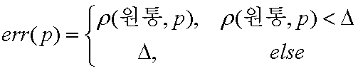
도 10에 도시된 바와 같이, 원통에 대한 초기 추정이 완료되면, 초기 추정에 대해 3차원 포인트들을 피팅(fitting)한다(94단계). 피팅은 비선형 최소 자승 최적화 방법(non-linear least square optimization)을 사용하여 이루어진다. 피팅에 대한 이상치의 영향을 최소화하기 위해 본 실시예에서는 3차원 포인트들에 대해 다음 식과 같이 표현되는 후버(Huber)의 m-추정기(m-estimator)를 적용하여 그 식을 만족하는 3차원 포인트들에 대해서 피팅한다.As shown in FIG. 10, upon completion of the initial estimation for the cylinder, fitting three-dimensional points to the initial estimation (step 94). Fitting is done using a non-linear least square optimization method. In this embodiment, in order to minimize the influence of the outlier on the fitting, three-dimensional points satisfying the equation are applied by applying a mover-estimator of Huber expressed as the following equation for the three-dimensional points. Fitting for.

여기서, ρ(원통, p)는 원통을 이루는 포인트와 이웃 포인트 p의 거리에 대한 함수이다. △는 임계치이다.Here, ρ (cylinder, p) is a function of the distance between the points forming the cylinder and the neighboring point p. Δ is a threshold.
정형화된 물체가 육면체인 경우 일반적인 평면 피팅 방법(generic plane fitting method)를 사용하여 점 구름으로부터 육면체를 재구성한다.If the shaped object is a cube, the cube is reconstructed from the point cloud using the generic plane fitting method.
도 11은 도 8의 84단계에 따른 비정형화된 물체를 모델링하는 방법을 설명하 는 흐름도이다. 먼저, 사용자 상호작용(User Interaction, UI)을 통해 두 영상으로부터 2D 스켈레톤(skeleton)을 추출한다(111단계). 이를 위해, 예를 들어 도 12(a) 및 12(b)에 도시된 영상에서 컵의 손잡이를 재구성하는 경우를 설명하기로 한다.FIG. 11 is a flowchart illustrating a method of modeling an atypical object according to step 84 of FIG. 8. First, a 2D skeleton is extracted from two images through user interaction (UI) (step 111). To this end, for example, a case of reconfiguring the handle of the cup in the image shown in Figs. 12 (a) and 12 (b) will be described.
먼저, UI를 통해 도 13(a)에 도시된 바와 같이 손잡이의 실루엣(130)에 대해 주요 포인트들(131)을 선택한다. 여기서 주요 포인트들은 실루엣의 모양 달라지는 부분, 즉 도 13(a)에 도시된 바와 같이 실루엣의 변곡점 부분들이 될 수 있다. 주요 포인트들이 선택되면, UI는 도 13(b)에 도시된 바와 같이 선택된 포인트들 사이를 연결한다. 연결된 포인트들의 내부에 대해 들로네 삼각화(Delaunay triagulation)에 따라 도 13(c)에 도시된 바와 같이 삼각형 모델을 완성한다. 다음으로, 보로노이 도(Voronoi diagram)에 따라 도 13(d)에 도시된 바와 같이 다각형 내부의 에지들(132)을 구한다. 또한 구해진 에지들을 도 14a 내지도 14c에 도시된 바와 같은 에지들중 하나로 분류한다. 도 14a는 종단 삼각형(terminal triangle)에 위치한 종단 에지(141), 도 14b는 2개의 이웃하는 에지를 갖는 중간 에지(intermediate edge, 142), 도 14c는 2개 이상의 이웃하는 에지를 갖는 접합점 에지(junction edge, 143)를 예시한 것이다.First, the
다음으로, 도 15에 도시된 바와 같이 종단 에지로부터 중간 에지들을 거쳐서 접합점 에지 또는 다른 종단 에지까지 연결하는 패스(path)를 만들어서 코히런트 스켈레톤 부분(skeleton parts)을 만든다. Next, as shown in FIG. 15, coherent skeleton parts are made by making a path connecting the end edge from the end edge to the junction point or another end edge.
다음으로, 종단 삼각형을 정렬하고(sorting), 단면에 대한 스위핑(sweeping)을 통해 도 16(a)에 도시된 바와 같이 단면 에지들(cross-section edges)(150)을 갖는 실루엣을 얻고, 단면 에지의 중간점을 연결하여 도 16(b)에 도시된 바와 같은 2D 스켈레톤(151)을 추출한다. Next, sorting the longitudinal triangles and sweeping the cross section to obtain a silhouette with
2D 스켈레톤이 추출되면, 이로부터 3D 스켈레톤을 구성한다(112단계). 3D 스켈레톤 구성을 위해 먼저, 추출된 복수의 2D 스켈레톤에 대한 비주얼 헐의 교차(intersection)을 만든다. 추출된 각 2D 스켈레톤은 라인 에지(line edge)의 세트이다. 에지의 비주얼 헐은 솔리드 각(solid angle)의 내부 면적이므로, 복수의 2D 스켈레톤으로부터 3D 스켈레톤을 구성하는 문제는 3차원 공간에서 두 솔리드 각이 교차되는 문제와 같다. 즉, 3D 스켈레톤은 두 2D 스켈레톤의 비주얼 헐을 교차함으로써 구성될 수 있다.When the 2D skeleton is extracted, a 3D skeleton is formed therefrom (step 112). To construct a 3D skeleton, we first create an intersection of the visual hulls for the extracted multiple 2D skeletons. Each 2D skeleton extracted is a set of line edges. Since the visual hull of the edge is the internal area of a solid angle, the problem of constructing a 3D skeleton from a plurality of 2D skeletons is the same as the problem of two solid angles intersecting in three-dimensional space. That is, the 3D skeleton can be constructed by intersecting the visual hulls of the two 2D skeletons.
다음으로, 도 17(a)에 도시된 바와 같은 2D 스켈레톤을 갖는 실루엣으로부터 3D 단면을 계산한다. 이를 위해, 3D 스켈레톤의 각 포인트에 대해 단면 에지는 화면 평면(screen plane)에서 3D 스켈레톤 포인트로 변환하고(translation), 원근변환(perspective transformation)을 이용하여 스케일링(scaling)한다. 여기서, 3D 스켈레톤 포인트들의 중간 포인트들(intermediate points)은 보간(interpolation)하여 계산되고, 계산된 포인트들을 화면 평면에 다시 투영하여 실루엣을 벗어나는 단면을 잘라냄으로써 3D 단면을 도 17(b)에 도시된 바와 같이 형성할 수 있다. 도 17(c)는 서로 다른 카메라 위치에서 계산된 3D 단면을 갖는 3D 스켈레톤을 도시한 것이다.Next, the 3D cross section is calculated from the silhouette having the 2D skeleton as shown in Fig. 17A. To this end, for each point in the 3D skeleton, the cross-sectional edge is transformed from the screen plane to the 3D skeleton point and scaled using perspective transformation. Here, intermediate points of the 3D skeleton points are calculated by interpolation, and the 3D cross-section is shown in FIG. 17B by cutting the cross-section out of silhouette by projecting the calculated points back to the screen plane. It can be formed as. FIG. 17C shows a 3D skeleton having a 3D cross section calculated at different camera positions.
113단계에서는 3D 스켈레톤에 대해 3D 볼륨(volume) 모델을 도 18과 같이 구성한다. 이를 위해, 먼저, 3D 스켈레톤 좌표를 소정 크기의 복셀(voxel) 공간에 맞 도록 변환하고, 3D 볼륨 구성을 위한 단면을 만든다. 단면은 각 3D 스켈레톤 에지의 두 포인트 및 두 포인트 사이에 만들어진다. 연속적인 모델을 만들기 위해 중간점을 계산하고, 선택된 단면 모양을 단면의 면적 제한(cross-section area constraints)에 맞도록 조절한다. 이렇게 만들어진 볼륨을 매끄럽게 하기 위해(smoothing) 가우스 필터(Gauss filter)가 사용될 수 있다. 도 19는 가우스 필터가 사용된 예를 도시한 것이다.In
볼륨을 매끄럽게 한 다음, 도 20(a)와 같이 실루엣(130)을 벗어난 볼륨 표면을 도 20(b)와 같이 잘라낸다. 잘라내는 외부 표면들의 수는 스무딩 필터(smoothing filter)의 크기에 따라 정해진다. After the volume is smoothed, the volume surface outside the
고품질의 모델을 얻기 위해, 입력 실루엣의 비주얼 헐을 이용하여 볼륨을 교정한다. 이 과정은 모델의 각 복셀을 실루엣 위로 투영함으로써 이루어진다. 도 21은 교정이 이루어진 결과를 도시한 것이다.To get a high quality model, use the visual hull of the input silhouette to correct the volume. This is done by projecting each voxel in the model onto the silhouette. 21 shows the result of the calibration.
3D 볼륨이 구성된 다음, 3D 다각형을 구성한다(114단계). 먼저, 공지의 에지 기반 알고리즘을 통해 등가면(isosurface)을 구성하고, 볼륨 모델을 만들기 위해 변환된 3D 스켈레톤 좌표를 역변환하여 다각형 모델을 만든다. 렌더링시 결함(artifacts)을 줄이기 위해 도 22(a)에 도시된 다각형 모델에서 도 22(b)에 도시된 바와 같이 삼각형들의 수를 줄일 수 있다. 다음으로 다각형 모델은 라플라샨 플로우 메쉬 필터(Laplacian flow mesh filter)를 반복적으로 적용함으로써 도 23에 도시된 바와 같이 매끄럽게 된다.After the 3D volume is constructed, a 3D polygon is constructed (step 114). First, an isosurface is constructed using known edge-based algorithms, and a polygon model is created by inversely transforming the transformed 3D skeleton coordinates to create a volume model. In order to reduce artifacts in rendering, the number of triangles may be reduced as shown in FIG. 22B in the polygonal model shown in FIG. 22A. The polygonal model is then smoothed as shown in FIG. 23 by repeatedly applying a Laplacian flow mesh filter.
본 발명은 3차원 네비게이션에(3D navigaton)에 적용할 수 있다. 도 24는 본 발명에 따른 3차원 네비게이션을 위한 영상 재구성 방법에 대한 흐름도를 도시한 것이다.The present invention can be applied to 3D navigation. 24 is a flowchart illustrating an image reconstruction method for 3D navigation according to the present invention.
먼저, 두 입력 영상에 대해 기준 물체를 정한 다음, 기준 물체에 육면체와 같은 정형화된 프레임을 배치한다(221단계). 도 25는 도로변 건물 씬의 일례를 도시한 것이다. 도 26(a) 및 도 26(b)는 카메라(240)의 방향에 따라 구도가 달라진 씬을 각각 도시한 것이다. 도 26(a)에서는 건물에 육면체(241)를 씌운 예를 도시한 것이다.First, a reference object is determined for two input images, and then a standardized frame such as a hexahedron is disposed on the reference object (step 221). 25 shows an example of a roadside building scene. 26 (a) and 26 (b) show scenes in which the composition is changed according to the direction of the
건물에 씌운 육면체의 코너점들을 각각 이용하여 두 영상에서 특징점들을 추출하고(222단계), 추출된 특징점들을 이용하여 카메라를 보정함으로써 영상에서 3차원 포인트들과 내부 및 외부 카메라 보정 정보를 얻는다(223단계). 여기서 카메라 보정은 도 1에 도시된 카메라 보정 방법에 따라 보정할 수 있고, 종래의 체크보드를 이용한 카메라 보정 방법에 따라 보정할 수도 있다.Extract the feature points from the two images by using the corner points of the hexahedron respectively (step 222), and obtain the 3D points and the internal and external camera correction information from the image by correcting the camera using the extracted feature points (223). step). The camera correction may be corrected according to the camera correction method shown in FIG. 1, or may be corrected according to a camera correction method using a conventional check board.
다음으로, 3차원 포인트들과 내부 및 외부 카메라 보정 정보를 이용하여 도 8에 도시된 영상 재생 방법에 따라 3차원 정형 및 비정형 물체, 즉 건물, 지형, 지물 등을 모델링한다(223단계).Next, using the 3D points and the internal and external camera correction information, three-dimensional shaped and atypical objects, that is, buildings, terrain, features, and the like, are modeled according to the image reproducing method illustrated in FIG. 8 (step 223).
본 발명은 또한 컴퓨터로 읽을 수 있는 코드로서 구현하는 것이 가능하다. 컴퓨터가 읽을 수 있는 기록매체는 컴퓨터 시스템에 의하여 읽혀질 수 있는 데이터가 저장되는 모든 종류의 기록장치를 포함한다. 컴퓨터가 읽을 수 있는 기록매체의 예로는 ROM, RAM, CD_ROM, 자기 테이프, 플로피 디스크 및 광 데이터 저장장치 등이 있으며, 또한 캐리어 웨이브, 예를 들어 인터넷을 통한 전송의 형태로 구현되는 것도 포함한다. 또한 컴퓨터가 읽을 수 있는 기록매체는 네트워크로 연결된 컴퓨터 시스템에 분산되어, 분산방식으로 컴퓨터가 읽을 수 있는 코드로 저장되고 실행될 수 있다.The invention can also be embodied as computer readable code. A computer-readable recording medium includes all kinds of recording apparatuses in which data that can be read by a computer system is stored. Examples of computer-readable recording media include ROM, RAM, CD_ROM, magnetic tape, floppy disks, optical data storage devices, and the like, and also include those implemented in the form of carrier waves, for example, transmission over the Internet. The computer readable recording medium may also be distributed over a networked computer system and stored and executed in computer readable code in a distributed manner.
본 발명에 따르면, 입력 영상 시퀀스로부터 보정물 없이 영상내 점들의 관계를 이용하여 카메라를 보정할 수 있다. 또한 카메라 보정 결과 얻어진 데이터를 이용하여 정형화된 물체 및 스케치 기반 편집을 통해 비정형화된 물체를 모델링할 수 있다.According to the present invention, the camera can be corrected using the relation of points in the image without correction from the input image sequence. The data obtained from the camera calibration can also be used to model atypical objects through sketch-based and sketch-based editing.
본 발명은 또한 건물, 지형, 지물의 모델링을 통해 행선지까지의 경로를 찾아주는 텔레메텍스(telematics)에 적용할 수 있고, 3차원 가상 쇼핑, 가상현실 또는 가상 체험 등에 사용할 수 있다. 또한 주변 환경과 같은 모델링이 가능하므로 3차원 시뮬레이션 게임 등에도 적용할 수 있다.The present invention can also be applied to telematics that find a route to a destination through modeling of buildings, terrain, and features, and can be used for 3D virtual shopping, virtual reality, or virtual experience. In addition, it can be applied to 3D simulation games because it can be modeled as the surrounding environment.
이상에서와 같이 도면과 명세서에서 최적 실시예가 개시되었다. 여기서, 특정한 용어들이 사용되었으나, 이는 단지 본 발명을 설명하기 위한 목적에서 사용된 것이지 의미한정이나 특허청구범위에 기재된 본 발명의 범위를 제한하기 위하여 사용된 것은 아니다. 그러므로 본 기술분야의 통상의 지식을 가진 자라면 이로부터 다양한 변형 및 균등한 타 실시예가 가능하다는 점을 이해할 것이다. 따라서, 본 발명의 진정한 기술적 보호 범위는 첨부된 특허청구범위의 기술적 사상에 의해 정해져야 할 것이다.As described above, optimal embodiments have been disclosed in the drawings and the specification. Although specific terms are used herein, they are used for the purpose of describing the present invention only and are not used to limit the scope of the present invention described in the meaning of the claims or the claims. Therefore, those skilled in the art will appreciate that various modifications and equivalent embodiments are possible without departing from the scope of the present invention. Accordingly, the true scope of the present invention should be determined by the technical idea of the appended claims.
Claims (32)


Priority Applications (2)
| Application Number | Priority Date | Filing Date | Title |
|---|---|---|---|
| KR1020060025209A KR101195942B1 (en) | 2006-03-20 | 2006-03-20 | Camera calibration method and 3D object reconstruction method using the same |
| US11/723,532 US8896665B2 (en) | 2006-03-20 | 2007-03-20 | Camera calibration method and medium and 3D object reconstruction method and medium using the same |
Applications Claiming Priority (1)
| Application Number | Priority Date | Filing Date | Title |
|---|---|---|---|
| KR1020060025209A KR101195942B1 (en) | 2006-03-20 | 2006-03-20 | Camera calibration method and 3D object reconstruction method using the same |
Publications (2)
| Publication Number | Publication Date |
|---|---|
| KR20070095040A KR20070095040A (en) | 2007-09-28 |
| KR101195942B1 true KR101195942B1 (en) | 2012-10-29 |
Family
ID=38648363
Family Applications (1)
| Application Number | Title | Priority Date | Filing Date |
|---|---|---|---|
| KR1020060025209A KR101195942B1 (en) | 2006-03-20 | 2006-03-20 | Camera calibration method and 3D object reconstruction method using the same |
Country Status (2)
| Country | Link |
|---|---|
| US (1) | US8896665B2 (en) |
| KR (1) | KR101195942B1 (en) |
Cited By (4)
| Publication number | Priority date | Publication date | Assignee | Title |
|---|---|---|---|---|
| KR20180077865A (en) | 2016-12-29 | 2018-07-09 | 단국대학교 산학협력단 | Online apparatus and method for Multiple Camera Multiple Target Tracking Based on Multiple Hypothesis Tracking |
| CN109598763A (en) * | 2018-11-30 | 2019-04-09 | Oppo广东移动通信有限公司 | Camera calibration method, device, electronic equipment and computer readable storage medium |
| US10757331B2 (en) | 2018-06-11 | 2020-08-25 | Semes Co., Ltd. | Camera posture estimation method and substrate processing apparatus |
| US12022052B2 (en) | 2020-08-25 | 2024-06-25 | Samsung Electronics Co., Ltd. | Method and apparatus for 3D reconstruction of planes perpendicular to ground |
Families Citing this family (65)
| Publication number | Priority date | Publication date | Assignee | Title |
|---|---|---|---|---|
| US7542034B2 (en) | 2004-09-23 | 2009-06-02 | Conversion Works, Inc. | System and method for processing video images |
| US8655052B2 (en) * | 2007-01-26 | 2014-02-18 | Intellectual Discovery Co., Ltd. | Methodology for 3D scene reconstruction from 2D image sequences |
| US8274530B2 (en) | 2007-03-12 | 2012-09-25 | Conversion Works, Inc. | Systems and methods for filling occluded information for 2-D to 3-D conversion |
| IL182799A (en) * | 2007-04-26 | 2014-11-30 | Nir Avrahami | Method for estimating the pose of a ptz camera |
| US9418474B2 (en) * | 2008-01-04 | 2016-08-16 | 3M Innovative Properties Company | Three-dimensional model refinement |
| TW200937348A (en) * | 2008-02-19 | 2009-09-01 | Univ Nat Chiao Tung | Calibration method for image capturing device |
| US8401276B1 (en) * | 2008-05-20 | 2013-03-19 | University Of Southern California | 3-D reconstruction and registration |
| US8854430B2 (en) * | 2008-05-23 | 2014-10-07 | Fei Company | Image data processing |
| US8548225B2 (en) * | 2008-08-15 | 2013-10-01 | Adobe Systems Incorporated | Point selection in bundle adjustment |
| JP4636146B2 (en) * | 2008-09-05 | 2011-02-23 | ソニー株式会社 | Image processing method, image processing apparatus, program, and image processing system |
| KR101166719B1 (en) | 2008-12-22 | 2012-07-19 | 한국전자통신연구원 | Method for calculating a limitless homography and method for reconstructing architecture of building using the same |
| GB2479537B8 (en) | 2010-04-12 | 2017-06-14 | Vitec Group Plc | Camera pose correction |
| WO2012044216A1 (en) * | 2010-10-01 | 2012-04-05 | Saab Ab | Method and apparatus for solving position and orientation from correlated point features in images |
| WO2012062813A2 (en) * | 2010-11-09 | 2012-05-18 | The Provost, Fellows, And Scholars Of The College Of The Holy And Undivided Trinity Of Queen Elizabeth, Near Dublin | Method and system for recovery of 3d scene structure and camera motion from a video sequence |
| US9147260B2 (en) * | 2010-12-20 | 2015-09-29 | International Business Machines Corporation | Detection and tracking of moving objects |
| FR2976107B1 (en) * | 2011-05-30 | 2014-01-03 | Commissariat Energie Atomique | METHOD FOR LOCATING A CAMERA AND 3D RECONSTRUCTION IN A PARTIALLY KNOWN ENVIRONMENT |
| JP5887770B2 (en) * | 2011-09-05 | 2016-03-16 | 富士ゼロックス株式会社 | Image processing apparatus and image processing program |
| US9462263B2 (en) * | 2011-11-07 | 2016-10-04 | Intel Corporation | Calibrating a one-dimensional coded light 3D acquisition system |
| WO2013173383A1 (en) * | 2012-05-15 | 2013-11-21 | Brilakis Ioannis | Methods and apparatus for processing image streams |
| US8416236B1 (en) * | 2012-07-19 | 2013-04-09 | Google Inc. | Calibration of devices used to generate images of a three-dimensional object data model |
| CN102982548B (en) * | 2012-12-11 | 2015-11-25 | 清华大学 | Multi-view stereoscopic video acquisition system and camera parameter scaling method thereof |
| US9177384B2 (en) * | 2013-07-31 | 2015-11-03 | Trimble Navigation Limited | Sequential rolling bundle adjustment |
| CN103099623B (en) * | 2013-01-25 | 2014-11-05 | 中国科学院自动化研究所 | Extraction method of kinesiology parameters |
| US9036044B1 (en) * | 2013-07-22 | 2015-05-19 | Google Inc. | Adjusting camera parameters associated with a plurality of images |
| KR20150089663A (en) * | 2014-01-28 | 2015-08-05 | 한국전자통신연구원 | Device for multi-shape primitives fitting of 3D point clouds using graph-based segmentation and method thereof |
| US11051000B2 (en) * | 2014-07-14 | 2021-06-29 | Mitsubishi Electric Research Laboratories, Inc. | Method for calibrating cameras with non-overlapping views |
| EP2983131A1 (en) * | 2014-08-06 | 2016-02-10 | Thomson Licensing | Method and device for camera calibration |
| US9491452B2 (en) | 2014-09-05 | 2016-11-08 | Intel Corporation | Camera calibration |
| US9846963B2 (en) * | 2014-10-03 | 2017-12-19 | Samsung Electronics Co., Ltd. | 3-dimensional model generation using edges |
| CN104887238A (en) * | 2015-06-10 | 2015-09-09 | 上海大学 | Hand rehabilitation training evaluation system and method based on motion capture |
| JP6503906B2 (en) * | 2015-06-10 | 2019-04-24 | 富士通株式会社 | Image processing apparatus, image processing method and image processing program |
| US9609242B2 (en) * | 2015-06-25 | 2017-03-28 | Intel Corporation | Auto-correction of depth-sensing camera data for planar target surfaces |
| US10186024B2 (en) * | 2015-12-29 | 2019-01-22 | Texas Instruments Incorporated | Method and system for real time structure from motion in a computer vision system |
| US11232583B2 (en) * | 2016-03-25 | 2022-01-25 | Samsung Electronics Co., Ltd. | Device for and method of determining a pose of a camera |
| JP6702543B2 (en) * | 2016-05-31 | 2020-06-03 | 株式会社東芝 | Information processing apparatus, method and program |
| GB2553293B (en) * | 2016-08-25 | 2022-06-01 | Advanced Risc Mach Ltd | Graphics processing systems and graphics processors |
| CN106530354B (en) * | 2016-10-31 | 2020-01-14 | 纵目科技(上海)股份有限公司 | Image processing device, image correction method, and calibration point searching method and system |
| CN106600642A (en) * | 2016-10-31 | 2017-04-26 | 纵目科技(上海)股份有限公司 | Image processing device, image correction method and system, and fixed point searching method and system |
| CN106709977B (en) * | 2016-11-16 | 2020-04-03 | 北京航空航天大学 | Automatic light source arrangement method based on scene night scene graph |
| US10630962B2 (en) * | 2017-01-04 | 2020-04-21 | Qualcomm Incorporated | Systems and methods for object location |
| CN106960470B (en) * | 2017-04-05 | 2022-04-22 | 未来科技(襄阳)有限公司 | Three-dimensional point cloud curved surface reconstruction method and device |
| CN109118542B (en) * | 2017-06-22 | 2021-11-23 | 阿波罗智能技术(北京)有限公司 | Calibration method, device, equipment and storage medium between laser radar and camera |
| EP3665653A4 (en) * | 2017-09-11 | 2021-09-29 | Track160, Ltd. | Techniques for rendering three-dimensional animated graphics from video |
| US10504244B2 (en) * | 2017-09-28 | 2019-12-10 | Baidu Usa Llc | Systems and methods to improve camera intrinsic parameter calibration |
| US11636668B2 (en) | 2017-11-10 | 2023-04-25 | Nvidia Corp. | Bilateral convolution layer network for processing point clouds |
| WO2019100216A1 (en) * | 2017-11-21 | 2019-05-31 | 深圳市柔宇科技有限公司 | 3d modeling method, electronic device, storage medium and program product |
| US10657712B2 (en) | 2018-05-25 | 2020-05-19 | Lowe's Companies, Inc. | System and techniques for automated mesh retopology |
| WO2020145668A1 (en) * | 2019-01-08 | 2020-07-16 | 삼성전자주식회사 | Method for processing and transmitting three-dimensional content |
| US11176704B2 (en) | 2019-01-22 | 2021-11-16 | Fyusion, Inc. | Object pose estimation in visual data |
| US10887582B2 (en) | 2019-01-22 | 2021-01-05 | Fyusion, Inc. | Object damage aggregation |
| US11783443B2 (en) | 2019-01-22 | 2023-10-10 | Fyusion, Inc. | Extraction of standardized images from a single view or multi-view capture |
| US11024054B2 (en) * | 2019-05-16 | 2021-06-01 | Here Global B.V. | Method, apparatus, and system for estimating the quality of camera pose data using ground control points of known quality |
| KR20190103085A (en) * | 2019-08-15 | 2019-09-04 | 엘지전자 주식회사 | Intelligent inspection devices |
| KR102593103B1 (en) * | 2019-10-28 | 2023-10-24 | 주식회사 케이티 | Apparatus, method and computer program for aligning of camera |
| US11562474B2 (en) * | 2020-01-16 | 2023-01-24 | Fyusion, Inc. | Mobile multi-camera multi-view capture |
| US11776142B2 (en) | 2020-01-16 | 2023-10-03 | Fyusion, Inc. | Structuring visual data |
| US11605151B2 (en) | 2021-03-02 | 2023-03-14 | Fyusion, Inc. | Vehicle undercarriage imaging |
| CN113034695B (en) * | 2021-04-16 | 2022-11-22 | 广东工业大学 | Wasserstein distance-based object envelope multi-view reconstruction and optimization method |
| CN113223175B (en) * | 2021-05-12 | 2023-05-05 | 武汉中仪物联技术股份有限公司 | Pipeline three-dimensional nonlinear model construction method and system based on real attitude angle |
| US11854224B2 (en) | 2021-07-23 | 2023-12-26 | Disney Enterprises, Inc. | Three-dimensional skeleton mapping |
| KR102612353B1 (en) * | 2021-09-02 | 2023-12-12 | 렉스젠(주) | Image analysis system and method thereto |
| US11550406B1 (en) | 2021-10-14 | 2023-01-10 | Autodesk, Inc. | Integration of a two-dimensional input device into a three-dimensional computing environment |
| US20230119646A1 (en) * | 2021-10-14 | 2023-04-20 | Autodesk, Inc. | Integration of a two-dimensional input device into a three-dimensional computing environment |
| CN114022555A (en) * | 2021-11-09 | 2022-02-08 | 扬州大学江都高端装备工程技术研究所 | Blow molding piece welding pose matching method based on joint line and wall thickness distribution characteristics |
| CN115272587B (en) * | 2022-09-26 | 2023-05-30 | 深圳市纵维立方科技有限公司 | Model file generation method and medium for 3D printing and electronic equipment |
Citations (1)
| Publication number | Priority date | Publication date | Assignee | Title |
|---|---|---|---|---|
| KR100327120B1 (en) | 1999-12-13 | 2002-03-13 | 오길록 | Image Registration Method Using 3D Tracker And Computer Vision For Augmented Reality |
Family Cites Families (16)
| Publication number | Priority date | Publication date | Assignee | Title |
|---|---|---|---|---|
| US1355277A (en) * | 1919-08-11 | 1920-10-12 | Automotive Parts Company | Lubricating system for fans |
| EP0791814A3 (en) | 1997-05-26 | 1997-11-26 | Martin Lehmann | Method for leak testing and leak testing apparatus |
| AU772276B2 (en) * | 2000-01-06 | 2004-04-22 | Eth Zurich | System and method for multi-resolution fairing of non-manifold models |
| JP2001245323A (en) | 2000-02-29 | 2001-09-07 | Minolta Co Ltd | Three-dimensional input method and device |
| JP3436929B2 (en) | 2001-03-30 | 2003-08-18 | 岩手県 | 3D shape measurement system |
| US6996254B2 (en) * | 2001-06-18 | 2006-02-07 | Microsoft Corporation | Incremental motion estimation through local bundle adjustment |
| US20030012410A1 (en) * | 2001-07-10 | 2003-01-16 | Nassir Navab | Tracking and pose estimation for augmented reality using real features |
| GB0125774D0 (en) * | 2001-10-26 | 2001-12-19 | Cableform Ltd | Method and apparatus for image matching |
| GB0208909D0 (en) | 2002-04-18 | 2002-05-29 | Canon Europa Nv | Three-dimensional computer modelling |
| JP3904988B2 (en) * | 2002-06-27 | 2007-04-11 | 株式会社東芝 | Image processing apparatus and method |
| US7343278B2 (en) * | 2002-10-22 | 2008-03-11 | Artoolworks, Inc. | Tracking a surface in a 3-dimensional scene using natural visual features of the surface |
| WO2004068300A2 (en) * | 2003-01-25 | 2004-08-12 | Purdue Research Foundation | Methods, systems, and data structures for performing searches on three dimensional objects |
| US7538774B2 (en) * | 2003-06-20 | 2009-05-26 | Nippon Telegraph And Telephone Corporation | Virtual visual point image generating method and 3-d image display method and device |
| WO2005008275A1 (en) * | 2003-07-08 | 2005-01-27 | Lightswitch Safety Systems, Inc. | Method and element for light detecting and angle of view compensation for optical devices |
| KR100511721B1 (en) | 2003-07-08 | 2005-09-02 | 재단법인서울대학교산학협력재단 | Method for matching a point of interest and assuming fundamental matrix |
| JP4241238B2 (en) * | 2003-08-29 | 2009-03-18 | 株式会社 日立ディスプレイズ | Liquid crystal display |
-
2006
- 2006-03-20 KR KR1020060025209A patent/KR101195942B1/en active IP Right Grant
-
2007
- 2007-03-20 US US11/723,532 patent/US8896665B2/en not_active Expired - Fee Related
Patent Citations (1)
| Publication number | Priority date | Publication date | Assignee | Title |
|---|---|---|---|---|
| KR100327120B1 (en) | 1999-12-13 | 2002-03-13 | 오길록 | Image Registration Method Using 3D Tracker And Computer Vision For Augmented Reality |
Cited By (5)
| Publication number | Priority date | Publication date | Assignee | Title |
|---|---|---|---|---|
| KR20180077865A (en) | 2016-12-29 | 2018-07-09 | 단국대학교 산학협력단 | Online apparatus and method for Multiple Camera Multiple Target Tracking Based on Multiple Hypothesis Tracking |
| US10757331B2 (en) | 2018-06-11 | 2020-08-25 | Semes Co., Ltd. | Camera posture estimation method and substrate processing apparatus |
| CN109598763A (en) * | 2018-11-30 | 2019-04-09 | Oppo广东移动通信有限公司 | Camera calibration method, device, electronic equipment and computer readable storage medium |
| CN109598763B (en) * | 2018-11-30 | 2020-07-21 | Oppo广东移动通信有限公司 | Camera calibration method, device, electronic equipment and computer-readable storage medium |
| US12022052B2 (en) | 2020-08-25 | 2024-06-25 | Samsung Electronics Co., Ltd. | Method and apparatus for 3D reconstruction of planes perpendicular to ground |
Also Published As
| Publication number | Publication date |
|---|---|
| KR20070095040A (en) | 2007-09-28 |
| US8896665B2 (en) | 2014-11-25 |
| US20070253618A1 (en) | 2007-11-01 |
Similar Documents
| Publication | Publication Date | Title |
|---|---|---|
| KR101195942B1 (en) | Camera calibration method and 3D object reconstruction method using the same | |
| CN105701857B (en) | Texturing of 3D modeled objects | |
| Habbecke et al. | A surface-growing approach to multi-view stereo reconstruction | |
| KR101554241B1 (en) | A method for depth map quality enhancement of defective pixel depth data values in a three-dimensional image | |
| JP4392507B2 (en) | 3D surface generation method | |
| Liao et al. | Modeling deformable objects from a single depth camera | |
| CN109242873A (en) | A method of 360 degree of real-time three-dimensionals are carried out to object based on consumer level color depth camera and are rebuild | |
| EP3367334B1 (en) | Depth estimation method and depth estimation apparatus of multi-view images | |
| Dick et al. | Automatic 3D Modelling of Architecture. | |
| WO2013029675A1 (en) | Method for estimating a camera motion and for determining a three-dimensional model of a real environment | |
| EP1063614A2 (en) | Apparatus for using a plurality of facial images from different viewpoints to generate a facial image from a new viewpoint, method thereof, application apparatus and storage medium | |
| Kuschk | Large scale urban reconstruction from remote sensing imagery | |
| CN114782628A (en) | Indoor real-time three-dimensional reconstruction method based on depth camera | |
| Alsadik | Guided close range photogrammetry for 3D modelling of cultural heritage sites | |
| Furukawa | High-fidelity image-based modeling | |
| Saxena et al. | 3-d reconstruction from sparse views using monocular vision | |
| JP3557168B2 (en) | Lens distortion coefficient calculation device and calculation method, computer-readable recording medium storing lens distortion coefficient calculation program | |
| Lhuillier | Toward flexible 3d modeling using a catadioptric camera | |
| WO2000004508A1 (en) | Automated 3d scene scanning from motion images | |
| JP3540696B2 (en) | Image synthesizing method, image synthesizing device, recording medium storing image synthesizing program | |
| Wang et al. | Automatic reconstruction of 3D environment using real terrain data and satellite images | |
| Purohit et al. | Multi-planar geometry and latent image recovery from a single motion-blurred image | |
| KR101673442B1 (en) | The method and apparatus for remeshing visual hull approximation by DBSS(displaced butterfly subdivision surface) | |
| Perrier et al. | Image-based view synthesis for enhanced perception in teleoperation | |
| JP2002170111A (en) | Image synthesizing apparatus and method and recording medium recording image synthesizing program |
Legal Events
| Date | Code | Title | Description |
|---|---|---|---|
| A201 | Request for examination | ||
| E701 | Decision to grant or registration of patent right | ||
| GRNT | Written decision to grant | ||
| FPAY | Annual fee payment |
Payment date: 20150916 Year of fee payment: 4 |
|
| FPAY | Annual fee payment |
Payment date: 20160921 Year of fee payment: 5 |
|
| FPAY | Annual fee payment |
Payment date: 20170918 Year of fee payment: 6 |
|
| FPAY | Annual fee payment |
Payment date: 20180917 Year of fee payment: 7 |
|
| FPAY | Annual fee payment |
Payment date: 20190910 Year of fee payment: 8 |