US7517015B2 - Headrest device - Google Patents
Headrest device Download PDFInfo
- Publication number
- US7517015B2 US7517015B2 US11/545,583 US54558306A US7517015B2 US 7517015 B2 US7517015 B2 US 7517015B2 US 54558306 A US54558306 A US 54558306A US 7517015 B2 US7517015 B2 US 7517015B2
- Authority
- US
- United States
- Prior art keywords
- link
- movable base
- connecting shaft
- fixed base
- base
- Prior art date
- Legal status (The legal status is an assumption and is not a legal conclusion. Google has not performed a legal analysis and makes no representation as to the accuracy of the status listed.)
- Expired - Fee Related
Links
- 238000001514 detection method Methods 0.000 claims abstract description 7
- 238000010276 construction Methods 0.000 description 25
- 206010044565 Tremor Diseases 0.000 description 2
- 208000027418 Wounds and injury Diseases 0.000 description 2
- 230000006378 damage Effects 0.000 description 2
- 230000000694 effects Effects 0.000 description 2
- 208000014674 injury Diseases 0.000 description 2
- 238000000034 method Methods 0.000 description 2
- 230000003213 activating effect Effects 0.000 description 1
- 238000013459 approach Methods 0.000 description 1
- 210000003679 cervix uteri Anatomy 0.000 description 1
- 230000005484 gravity Effects 0.000 description 1
Images


Classifications
-
- B—PERFORMING OPERATIONS; TRANSPORTING
- B60—VEHICLES IN GENERAL
- B60N—SEATS SPECIALLY ADAPTED FOR VEHICLES; VEHICLE PASSENGER ACCOMMODATION NOT OTHERWISE PROVIDED FOR
- B60N2/00—Seats specially adapted for vehicles; Arrangement or mounting of seats in vehicles
- B60N2/24—Seats specially adapted for vehicles; Arrangement or mounting of seats in vehicles for particular purposes or particular vehicles
- B60N2/42—Seats specially adapted for vehicles; Arrangement or mounting of seats in vehicles for particular purposes or particular vehicles the seat constructed to protect the occupant from the effect of abnormal g-forces, e.g. crash or safety seats
- B60N2/4207—Seats specially adapted for vehicles; Arrangement or mounting of seats in vehicles for particular purposes or particular vehicles the seat constructed to protect the occupant from the effect of abnormal g-forces, e.g. crash or safety seats characterised by the direction of the g-forces
- B60N2/4214—Seats specially adapted for vehicles; Arrangement or mounting of seats in vehicles for particular purposes or particular vehicles the seat constructed to protect the occupant from the effect of abnormal g-forces, e.g. crash or safety seats characterised by the direction of the g-forces longitudinal
- B60N2/4228—Seats specially adapted for vehicles; Arrangement or mounting of seats in vehicles for particular purposes or particular vehicles the seat constructed to protect the occupant from the effect of abnormal g-forces, e.g. crash or safety seats characterised by the direction of the g-forces longitudinal due to impact coming from the rear
-
- B—PERFORMING OPERATIONS; TRANSPORTING
- B60—VEHICLES IN GENERAL
- B60N—SEATS SPECIALLY ADAPTED FOR VEHICLES; VEHICLE PASSENGER ACCOMMODATION NOT OTHERWISE PROVIDED FOR
- B60N2/00—Seats specially adapted for vehicles; Arrangement or mounting of seats in vehicles
- B60N2/80—Head-rests
- B60N2/888—Head-rests with arrangements for protecting against abnormal g-forces, e.g. by displacement of the head-rest
Definitions
- the present invention relates to a headrest device.
- a headrest device is mounted on a vehicle, which a headrest device mitigates an impact applied to a cervix by restricting a backward movement of a head of an occupant after moving forward when the vehicle is rear-ended or when that the vehicle is to be rear-ended is predicted.
- a headrest device described in JPH11-334439A includes a drive motor provided in a headrest, a worm fixed to a rotational shaft of the drive motor, and a gear that is engaged with the worm.
- the drive motor is activated by signals transmitted from a sensor which is mounted on a vehicle to predict or detect rear-end collision.
- the headrest device when the collision is either predicted or detected, the headrest is tiled forward by activating the drive motor to protect a head of an occupant and to prevent the occupant from causing hyperextension-hyperflexion injury when the vehicle is rear-ended.
- a stepping motor and a gear mechanism vibrates stays which support a headrest and an attitude of the headrest is fixed when the vehicle is rear-ended, in order to prevent the occupant form causing hyperextension-hyperflexion injury.
- a need thus exists for a headrest device which securely supports a head of an occupant, prevents a load by an impact of the head against a headrest from being applied to a drive portion of the headrest, and downsizes and reduces the weight thereof.
- the present invention provides a headrest device, which includes a fixed base being supported by a seatback, a movable base disposed at a forward position relative to the fixed base, at least one first link being rotatably supported by a connecting shaft provided between the movable base and the fixed base, the first link having a first end connected to the movable base and a second end connected to the fixed base, at least one second link being supported by the connecting shaft so as to rotate relative to the first link, the second link having a first end connected to the movable base and a second end connected to the fixed base, a connection portion including the first link and the second link and connecting the movable base and the fixed base to be relatively movable by a relative rotation between the first link and the second link, a drive portion relatively rotating the first link and the second link in a direction so as to deploy the movable base away from the fixed base on the basis of a detected result by a rear-end collision detection means which is connected to the connection portion to detect and/or
- FIG. 1 is a lateral view of a vehicle provided with a seat for a vehicle having a headrest device according to an embodiment of the present invention.
- FIG. 2 is a lateral view of the vehicle provided with the seat for the vehicle having the headrest device according to the embodiment of the present invention.
- FIG. 3 is a perspective view of a headrest device according to the embodiment of the present invention.
- FIG. 4 is a lateral view of the headrest device according to the embodiment of the present invention.
- FIG. 5 is a lateral view of the headrest device according to the embodiment of the present invention.
- FIG. 6 is a lateral view of the headrest device according to the embodiment of the present invention.
- FIG. 7A is a cross-sectional view of FIG. 7B taken on line 7 A- 7 A according to the embodiment of the present invention.
- FIG. 7B is a magnified view of a portion A in FIG. 5 according to the embodiment of the present invention.
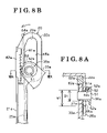
- FIG. 8A is a cross-sectional view of FIG. 8B taken on line 8 A- 8 A according to the embodiment of the present invention.
- FIG. 8B is a magnified view of a portion B in FIG. 6 according to the embodiment of the present invention.
- FIG. 9 is a partial enlarged view according to a modified example of the present invention.
- FIG. 10 is a partial enlarged view according to the modified example of the present invention.
- a vehicle 3 is provided with a seat 2 for a vehicle.
- the seat 2 for the vehicle includes a seat cushion 2 a maintained in a vehicle compartment, a seatback 2 b supported at a rear end of the seat cushion 2 a so as to rotate in a longitudinal direction of the vehicle (i.e., right-left direction in FIG. 1 ), and a headrest 2 c supported by the seatback 2 b.
- the headrest 2 c includes a headrest device 1 which forms a part of a frame of the headrest 2 c.
- the headrest 1 is housed in a space formed between a front cover 4 a which forms a front side of the headrest 2 c and a rear cover 4 b which forms a rear side of the headrest 2 c , and is supported by a headrest stay 4 c provided at a top end portion of the seatback 2 b to be positioned at a top part of the seat back 2 b.
- the headrest device 1 is connected to a controller 5 , and a detection signal is inputted from a sensor 6 serving as a rear-end collision detecting means which predicts or detects rear-ending to a vehicle.
- the controller 5 moves the front cover 4 a in a front-back direction of an occupant seated on the seat 2 , that is a longitudinal direction of the vehicle, relative to the rear cover 4 b according to the embodiment of the present invention.
- the controller 5 moves the front cover 4 from a normal position (i.e., a retracted position shown in FIG.
- the controller 5 and the sensor 6 may be integrally constructed with the headrest device 1 .
- the headrest device 1 includes a fixed base 10 and a movable base 20 which are arranged in parallel to each other, and a connecting portion 30 which connects the fixed base 10 and the movable base 20 .
- the movable base 20 is positioned forward relative to the fixed base 10 .
- the headrest device 1 includes a drive portion 7 connected to the controller 5 (shown in FIG. 1 ).
- the drive portion 7 includes a motor 7 A which is configured to rotate in a positive and reverse direction and a reduction gear which reduces a rotation speed of the motor 7 A.
- the drive portion 7 reduces the rotation speed of the motor 7 A by the reduction gear to rotate an output shaft 7 a in a positive and reverse direction.
- the fixed base 10 is disposed rearward relative to the movable base 20 and fixed to the headrest stay 4 c together with the rear cover 4 b.
- the fixed base 10 includes a fixed plate 11 which extends vertically and connection portions 12 a , 12 b which are plates perpendicularly extended from side end portions of the fixed plate 11 towards the movable base 20 .
- a back surface 11 a of the fixed plate 11 is in contact with the headrest stay 4 c.
- the drive portion 7 is fixed on a front surface 11 b of the fixed plate 11 .
- the connecting portion 30 is connected to the connection portions 12 a , 12 b.
- the front cover 4 a (shown in FIGS. 1-2 ) is fixed to a front side of the movable base 20 .
- the movable base 20 includes a movable plate 21 extended vertically, and connection portions 22 a , 22 b extended approximately perpendicular to the fixed base 10 from side end portions of the movable plate 21 respectively.
- the movable plate 21 is arranged approximately parallel to the fixed plate 11 of the fixed base 10 .
- the front cover 4 a is fixed on a front surface 21 a of the movable plate 21 . Accordingly, the movable plate 21 supports a head of an occupant seated on the seat 2 through the front cover 4 a.
- the connection portions 22 a , 22 b are connected to the connecting portion 30 .
- the connecting portion 30 is positioned between the movable base 20 and the fixed base 10 , and includes a connecting shaft 31 extended approximately parallel to the fixed plate 11 and the movable plate 21 , and a pair of X-links 32 a , 32 b connected by the connecting shaft 31 .
- the connecting shaft 31 is arranged to be approximately perpendicular to a rotational direction of the X-links 32 a , 32 b , and is connected to the output shaft 7 a of the drive portion 7 by means of a link mechanism 8 .
- the connecting shaft 31 is selectively biased forward (i.e., to the left in FIGS. 4 and 5 ) or backward (i.e., to the right in FIGS. 4 and 5 ) in accordance with a rotational direction of the output shaft 7 a.
- the X-links 32 a , 32 b are provided at first and second ends of the connecting shaft 31 respectively.
- the X-links 32 a , 32 b include first links 33 a , 33 b and second links 34 a , 34 b.
- the first link 33 a and the second link 34 a are positioned to cross each other so as to rotate about the connecting shaft 31 .
- the first link 33 b and the second link 34 b are positioned to cross each other so as to rotate about the connecting shaft 31 .
- the first links 33 a , 33 b are slidably connected to the fixed base 10 and the movable base 20 . More particularly, slits 13 a , 13 b vertically extended are formed at bottom ends of the connection portions 12 a , 12 b of the fixed base 10 respectively. Slidable connecting shafts 35 a , 35 b are provided at first ends (i.e., rear ends) of the first links 33 a , 33 b. The slidable connecting shafts 35 a , 35 b are accommodated in the slits 13 a , 13 b respectively so that the first links 33 a , 33 b are slidably connected to the fixed base 10 .
- Slide guiding bores 23 a , 23 b which extend vertically are formed at top ends of the connection portions 22 a , 22 b of the movable base 20 respectively.
- Slidable connecting shafts 36 a , 36 b are provided at second ends (i.e., front ends) of the first links 33 a , 33 b respectively.
- the slidable connecting shafts 36 a , 36 b are accommodated in the slide guiding bores 23 a , 23 b respectively so that the first links 33 a , 33 b are slidably connected to the movable base 20 .
- the second links 34 a , 34 b are rotatably connected to the fixed base 10 and the movable base 20 .
- Connection holes 14 a , 14 b are formed at top ends of the connection portions 12 a , 12 b of the fixed base 10 respectively.
- Rotatable connecting shafts 37 a , 37 b are provided at first ends (i.e., rear ends) of the second links 34 a , 34 b respectively.
- the rotatable connecting shafts 37 a , 37 b are accommodated in the connection holes 14 a , 14 b respectively so that the second links 34 a , 34 b are rotatably connected to the fixed base 10 .
- Connection holes 24 a , 24 b are respectively provided at bottom ends of the connection portions 22 a , 22 b of the movable base 20 (shown in FIGS. 4-6 ).
- Rotatable connecting shafts 38 a , 38 b are provided at second ends (i.e., front ends) of the second links 34 a , 34 b respectively.
- the rotatable connecting shafts 38 a , 38 b are respectively fitted into the connection holes 24 a , 24 b so that the second links 34 a , 34 b are rotatably connected to the movable base 20 .
- the slide guiding bores 23 a , 23 b which the slidable connecting shafts 36 a , 36 b of the first links 33 a , 33 b respectively are fitted through, are configured to allow the slidable connecting shafts 36 a , 36 b to move in a front-back direction of the headrest (i.e., there is a clearance between the connecting shafts 36 a , 36 b and the slide guiding bores 23 a , 23 b respectively).
- FIGS. 7-8 constructions of the slidable connecting shafts 36 a , 36 b and the slide guiding bores 23 a , 23 b will be explained in details as follows.
- each of the slidable connecting shafts 36 a , 36 b of the first links 33 a , 33 b includes a pin 51 (i.e., serving as a slidable connecting shaft) which penetrates the first links 33 a , 33 b in a plate thickness direction, and a bushing 52 (i.e., serving as a slidable connecting shaft) provided coaxially to the pin 51 .
- Front sidewall surfaces 61 a , 61 b are concaved at the slide guiding bores 23 a , 23 b.
- the slide guiding bores 23 a , 23 b has width W 1 which is longer than diameter D 1 of the bushing 52 (shown in FIG. 7A ).
- the bushing 52 includes a flange portion 52 a which projects outward in a radial direction from an end thereof. An external diameter of the flange portion 52 a is longer than the width W 1 of the slide guiding bores 23 a , 23 b.
- the movable base 20 moves (i.e., rotates) backward rotating about the rotatable connecting shafts 38 a , 38 b within a range (i.e., serving as a clearance between the slidable connecting shafts and the slide guiding bores respectively) allowed by the width W 1 of the slide guiding bore 23 a, 23 b , and thus the first links 33 a , 33 b and the movable base 20 are selectively contacted to each other or separated from each other.
- the slide guiding bores 23 a , 23 b are long bores which include a wider width portion and a narrower width portion, which a narrower width portion narrows gradually, as shown in FIG. 7B .
- the slidable connecting shafts 36 a , 36 b are fitted into the narrower width portion of the slide guiding bores 23 a , 23 b , respectively, when the movable base 20 is retracted.
- the slidable connecting shafts 36 a , 36 b are in the wider width portion of the slide guiding bores 23 a , 23 b , respectively, when the movable base 20 is deployed.
- a clearance between the slidable connecting shafts 36 a , 36 b and the slide guiding bores 23 a, 23 b , respectively, in a state where the movable base 20 is retracted becomes narrower than a clearance between the slidable connecting shafts 36 a , 36 b and the slide guiding bores 23 a, 23 b , respectively, in a state where the movable base 20 is deployed or in a process of being deployed from the fixed base 10 .
- shakiness of the headrest can be prevented in a state where the movable base 20 is retracted.
- the movable base 20 is provided with latches 62 a , 62 b (i.e., serving as a relative rotation restricting portion; serving as a second engaging portion) which contact the first links 33 a , 33 b respectively by a relative rotation between the movable base 20 and the second links 34 a , 34 b about the rotatable connecting shafts 38 a , 38 b.
- latches 62 a , 62 b i.e., serving as a relative rotation restricting portion; serving as a second engaging portion
- the latches 62 a , 62 b are provided at positions where the latches 62 a , 62 b contact the first links 33 a , 33 b of the movable plate 21 , and are extended in a sliding direction of the first links 33 a , 33 b.
- Plural teeth 63 a , 63 b i.e., serving as a first engaging portion are formed at the second end portions of the first links 33 a , 33 b opposing to the latches 62 a , 62 b respectively.
- a movement of the slidable connecting shafts 36 a , 36 b in the slide guiding bores 23 a , 23 b is prevented by a respective engagement between the first links 33 a , 33 b (i.e., serving as a first engaging portion) and the latches 62 a , 62 b (i.e., serving as a second engaging portion).
- a sliding movement of the slidable connecting shafts 36 a , 36 b in the slide guiding bores 23 a , 23 b is locked (prevented) by a latch mechanism including the teeth 63 a , 63 b (i.e., the first engaging portion) of the first links 33 a , 33 b and the latches 62 a, 62 b (i.e., second engaging portion).
- Springs 64 a , 64 b are provided at the movable base 20 .
- the springs 64 a , 64 b formed in a bar/stick shape extended in a longitudinal direction of the slide guiding bores 23 a, 23 b.
- the springs 64 a , 64 b are provided between the connection portions 22 a , 22 b of the movable base 20 and the flange portion 52 a of the bushing 52 respectively in a plate thickness direction (i.e., right, left direction in FIGS. 7A and 8A ) of the connection portions 22 a , 22 b, and are fixed to outer surfaces 26 a , 26 b of the connection portions 22 a , 22 b by means of fixing support portions 25 a , 25 b respectively.
- the springs 64 a , 64 b are positioned distance W 2 distant from rear side wall surfaces 65 a , 65 b of the slide guiding bores 23 a , 23 b respectively, which distance W 2 is shorter than the width W 1 of the slide guiding bores 23 a , 23 b in a front-back direction and is longer than diameter D 1 of the slidable connecting shafts 36 a , 36 b.
- a movement of the slidable connecting shafts 36 a , 36 b towards the front side wall surfaces 61 a , 61 b is prevented by the springs 64 a , 64 b respectively. Accordingly, the first links 33 a , 33 b slide relative to the movable base 20 without contacting the latches 62 a , 62 b.
- the springs 64 a , 64 b have elasticity, and the springs 64 a , 64 b are configured to deflect forward when a force greater than a predetermined load (e.g., a load applied to the movable base 20 and transmitted to the slidable connecting shafts 36 a , 36 b when the headrest device 1 supports a head of an occupant at rear-end collision) is applied thereto from the slidable connection shafts 36 a , 36 b.
- a predetermined load e.g., a load applied to the movable base 20 and transmitted to the slidable connecting shafts 36 a , 36 b when the headrest device 1 supports a head of an occupant at rear-end collision
- the first links 33 a , 33 b and the second links 34 a , 34 b rotate in opposite directions from one another about the connecting shaft 31 .
- the second links 34 a , 34 b rotate counterclockwise in FIG. 4 about the rotatable connecting shafts 37 a , 37 b.
- the first links 33 a , 33 b are guided by the slits 13 a , 13 b and the slidable guiding bores 23 a , 23 b respectively to rotate counterclockwise about the connecting shaft 31 .
- the first links 33 a, 33 b and the second links 34 a , 34 b rotate about the connecting shaft 31 in opposite directions from one another to move the movable base 20 to be away from the fixed base 10 .
- the X-links 32 a , 32 b rotate, and the movable base 20 is deployed away from the fixed base 10 to stop at the forward position (i.e., shown in FIG. 2 ).
- the second links 34 a , 34 b are connected to top end portions of the fixed base 10 and the second ends of the second links 34 a , 34 b are connected to bottom end portions of the movable base 20 , when the second links 34 a , 34 b rotate clockwise in FIG. 4 about the rotatable connecting shafts 37 a , 37 b , the movable base 20 is deployed away from the fixed base 10 and moves upward relative to the fixed base 10 . Accordingly, the headrest device 1 is deployed forward while displacing in an obliquely upward direction.
- the drive portion 7 drives the X-links 32 a , 32 b on the basis of control signals from the controller 5 so that the movable base 20 retracts back to the fixed base 10 . More particularly, first, the connecting shaft 31 , which connects the X-links 32 a and 32 b , moves backward by the link mechanism 8 .
- the first links 33 a , 33 b and the second links 34 a , 34 b rotate about the connecting shaft 31 in the opposite directions from one another.
- the second links 34 a , 34 b rotate counterclockwise in FIG. 5 about the rotatable connecting shafts 37 a , 37 b.
- the first links 33 a , 33 b are guided by the slits 13 a , 13 b and the slidable guiding bores 23 a , 23 b , respectively, to rotate clockwise about the connecting shaft 31 .
- the first links 33 a , 33 b and the second links 34 a , 34 b rotate about the connecting shaft 31 and the movable base 20 retracts back to the fixed base 10 .
- the X-links 32 a , 32 b rotate and the movable base 20 retracts back to the fixed base 10 to stop at a retracted position. Accordingly, the headrest device 1 is retracted rearward.
- FIGS. 6-8 An operation of the headrest device 1 at a rear-end collision will be explained as follows. As shown in FIGS. 6-8 , when a load greater than a predetermined load is applied from a front side of the headrest device 1 (i.e., a head of an occupant is supported by the movable base 20 at a rear-end collision), the springs 64 a , 64 b are deflected, and a top end portion of the movable base 20 is tilted towards the fixed base 10 pivotally about the rotatable connecting shafts 38 a , 38 b.
- the front side wall surfaces 61 a , 61 b of the slide guiding bores 23 a , 23 b move towards the slidable connecting shafts 36 a , 36 b , the teeth 63 a, 63 b of the first links 33 a , 33 b and the latches 62 a , 62 b of the movable base 20 contact one another, and the latches 62 a , 62 b are engaged with the teeth 63 a , 63 b formed on the first links 33 a , 33 b respectively (shown in FIGS. 7 and 8 ).
- the slide movement of the first links 33 a , 33 b is restricted by the latch mechanism including the latches 62 a , 62 b and the teeth 63 a , 63 b. Because the second links 34 a , 34 b connected to the movable base 20 is configured to be allowed only to rotate, relative rotations between the first links 33 a , 33 b and the second links 34 a , 34 b are prevented when the slide movement of the first links 33 a , 33 b is prevented.
- the slidable connecting shafts 36 a , 36 b moves to the rear side wall surfaces 65 a , 65 b in the slide guiding bores 23 a , 23 b , and the respective engagements between the teeth 63 a , 63 b and the latches 62 a , 62 b are released. That is, the springs 64 a , 64 b serve as a biasing portion which separates the first links 33 a , 33 b from the latches 62 a , 62 b.
- first links 33 a , 33 b and the second links 34 a , 34 b become relatively rotatable, and the X-links 32 a , 32 b enable to relatively move the movable base 20 and the fixed base 10 again.
- the load applied to the movable base 20 is equal to or less than the predetermined load, relative rotations between the first links 33 a , 33 b and the second links 34 a , 34 b are not restricted because the first links 33 a , 33 b and the latches 62 a , 62 b are not engaged.
- the load applied to the movable base 20 is supported by the fixed base 10 and the connecting portion 30 at which the relative rotation between the first links 33 a , 33 b and the second links 34 a , 34 b is restricted by the latches (i.e., relative rotation restricting portion) 62 a , 62 b. Accordingly, the movable base 20 securely supports a head of an occupant at a position apart from the fixed base 10 , where the movable base 20 is not retracted back by a load imposed thereon at a rear-end collision.
- the load which is applied to the movable base 20 is supported by the connecting portion 30 and the fixed base 10 and is not transmitted to the drive portion 7 .
- a small size motor when a motor is applied as the drive portion 7 , a small size motor can be used because a torque having a degree that can support a load applied to the movable base is not necessary. Further, in case a spring is applied as the drive portion, elastic force that can support a load applied to the movable base is not necessary. Accordingly, a smaller size drive portion than known headrest devices can be applied, which contributes to lightening and downsizing the headrest device.
- Slide movement of the first links 33 a , 33 b is restricted by the latch mechanism including the teeth 63 a , 63 b serving as a first engaging portion respectively provided at the first links 33 a , 33 b , and the latches 62 a , 62 b serving as a second engaging portion provided at the movable base 20 . Accordingly, for example, compared to a case where a slide movement of the first links are prevented by frictions, the slide movement of the first links can be restricted more securely.
- latches 62 a , 62 b are arranged along a sliding direction of the slidable connecting shafts 36 a , 36 b , engageable positions between the latches 62 a , 62 b and the teeth 63 a , 63 b are determined with short intervals in a sliding direction of the first links 33 a , 33 b.
- This construction enables the headrest device to flexibly respond to contact positions between the first links 33 a , 33 b and the latches 62 a , 62 b respectively, which contact positions vary in accordance with a relative distance between the movable base 20 and the fixed base 10 . That is, relative movement between the movable base 20 and the fixed base 10 can be restricted even in a state where the movable base 20 is not fully moved to the forward position.
- the headrest device 1 By rotating the motor 7 A in a normal direction or reverse direction, the headrest device 1 can be deployed or retracted without manual operation by an occupant.
- the springs 64 a , 64 b serving as the biasing member are provided.
- aforementioned effects (1) and (2) can be achieved.
- the movable base 20 is driven by the motor 7 A in a direction being away from the fixed base by the motor 7 A which can rotate in a normal direction and a reverse direction with the construction of the foregoing embodiment
- the construction of the present invention is not limited.
- the movable base and the fixed base may be biased in a direction deployed away from each other by a biasing force of a spring.
- a load applied to the headrest device at rear-end collision is supported by the connection portion by a restriction of the rotation between the first links and the second links. Accordingly, a head of an occupant can be appropriately supported even if the spring does not have an elastic force which can support a load applied to the movable base, and thus contributing to downsizing a drive portion.
- the connecting portion 30 includes pairs of X-links 32 a and 32 b which are connected by the connecting shaft 31 according to the embodiment of the present invention, equal to or more than three links may be applied. Further, although a single X-link may be provided on the connecting portion 30 , in that case, a guide member which supports an attitude of the X-link and a movement in a thickness direction is required.
- the latches 62 a , 62 b are provided at the positions which contact the first links 33 a , 33 b when the movable base 20 moves rearward, and a slide movement of the first links 33 a , 33 b is restricted by the latch mechanism including the teeth 63 a , 63 b serving as the first engaging portion and the latches 62 a , 62 b serving as the second engaging portion.
- the construction of the present invention is not limited to this construction.
- the second engaging portion may be a groove or/and a pin, or the like, which is formed at a position contacting the first links of the movable base, and is variable.
- the construction of the first engaging portion can be varied likewise.
- a fitting portion which fits to the slidable connecting shaft may be provided on the front side wall surface of the slide guiding bore, and the slide movement of the first links may be restricted by fitting the slide connecting shaft and the fitting portion.
- a biasing portion e.g., a spring which makes the movable base tilt in a direction to disengage the latches and the first links
- a biasing portion e.g., a spring which makes the movable base tilt in a direction to disengage the latches and the first links
- a hook 73 which contacts a spring 71 from the same side with a slidable connecting shaft 72 may be provided.
- a movement of the spring 71 towards the slidable connecting shaft 72 is prevented by the hook 73 , and a risk of a slide movement of the slidable connecting shaft 72 in a slide guiding bore 74 is reduced by the spring 71 .
- the latches i.e., the relative rotation restricting portion
- the teeth 63 a , 63 b are provided at the side of the first links 33 a , 33 b that is close to the movable base 20
- the latches 62 a , 62 b and the teeth 63 a , 63 b of the first links 33 a , 33 b may be provided at the side closer to or on the fixed base.
- the latches (i.e., relative rotation restricting portion) 62 a , 62 b and the respective first links 33 a , 33 b can be contacted more securely when a load is imposed on the movable base 20 compared to a case when the latches (i.e., relative rotation restricting portion) are provide at the fixed base.
- the latches i.e. relative rotation restricting portion
- the relative rotation restricting position may be provided at a bottom end portion of the movable base, and construction can be varied.
- the latches may be more securely engaged with the first links when the latches are provided at the top end portion of the movable base than at the bottom end portion because the movable base supports a head of an occupant at the top end thereof at rear-end collision.
- connection portion 30 is driven by the link mechanism 8 according to the embodiment, a method for transmitting a drive force from the drive portion to the connection portion may be varied.
- the second links 34 a , 34 b are connected to the top end portion of the fixed base 10 and the bottom end portion of the movable base 20 so as to rotate according to the embodiment, the construction of the present invention is not limited.
- the first links may be connected to the top end portion of the fixed base and the bottom end portion of the movable base so as to slide.
- the headrest device 1 which can follow a behavior of a head of an occupant, which is likely floated upward when a vehicle is rear-ended, can be attained.
- first links 33 a , 33 b are connected to the fixed base 10 and the movable base 20 to be slidable and the second links 34 a , 34 b are connected to the fixed base 10 and the movable base 20 to be rotatable according to the embodiment
- the construction of the present invention is not limited to this construction.
- a first end of a first link may be connected to a fixed base and a movable base to be rotatable and a second end of the first link may be connected to the fixed base and the movable base to be slidable, and constructions can be varied.
- the construction of the present invention is not limited to this construction.
- the movable base 20 may be moved rearward by biasing the bottom end of the movable base 20 rearward by a manual operation of an occupant.
- the X-links 32 a and 32 b are provided at respective ends of the connecting shaft 31 and are driven integrally by means of the connecting shaft 31 , the construction of the present invention is not limited to this construction. In this regard, by integrally driving the X-links 32 a and 32 b by means of the connecting shaft 31 , operations of the X-links 32 a and 32 b accord with each other, which enables to securely support a head of an occupant.
- a distance between the movable base and the fixed base is maintained when the movable base retracts back to (i.e. approaches) or deploys away from the fixed base in accordance with a relative rotation between the first links and the second links, and when the relative rotation between the first links and the second links is restricted by the relative rotation restricting portion.
- the movable base can securely support a head of an occupant at a position deployed away from the fixed base without being moved back by a load applied to the movable base at rear-end collision.
- the load applied to the movable base is supported by the fixed base and the connection portion where the relative rotation between the first links and the second links is restricted, the load imposed on the movable base is not transmitted to the drive portion.
- a motor when a motor is applied as the drive portion, a small size motor can be applied because a torque with a degree, which can support the load applied to the movable base, is not necessary.
- a spring when a spring is applied as the drive portion, elastic force with a degree, which can support the load applied to the movable base, is not necessary. Accordingly, compared to the known headrest devices, a smaller size drive portion can be used, which contributes to lightening and downsizing the headrest device.
- a slide movement of the slidable connecting shaft which is slidably connected to the movable base is restricted by a load applied to the movable base.
- a slide movement of the first links is prevented at at least one of the movable base and the fixed base which are connected to the second links which is only allowed to rotate, a rotation of the first links and the second links about the connecting shaft is restricted. Accordingly, a relative rotation between the first links and the second links is restricted in accordance with a degree of the load applied to the movable base, and a predetermined distance between the movable base and the fixed base can be maintained.
- the first links and the relative rotation restricting portion are biased to be disengaged from each other by biasing force of the biasing portion, when a degree of a load applied to the movable base becomes less than the biasing force of the biasing portion, the first links and the relative rotation restricting portion are disengaged so as to release a restriction by the relative rotation restricting portion. Accordingly, the restriction by the relative rotation restricting portion can be released without manual operation by an occupant.
- a slide movement of a first link is prevented by friction
- a slide movement of the slidable connecting shaft along the slide guiding bore can be securely restricted.
- the biasing portion is deflected, for example, towards the slidable connecting shaft, a slide movement of the slidable connecting shaft is not prevented.
- the headrest device can be deployed or retracted by rotating the motor in a normal direction or reverse direction.
- shakiness of the headrest can be prevented in a state where the movable base is retracted.
- a headrest device which securely supports a head of an occupant, prevents an application of a load by the head at a rear-end collision, and contributes to lightening and downsizing thereof can be provided.
Landscapes
- Engineering & Computer Science (AREA)
- Aviation & Aerospace Engineering (AREA)
- Transportation (AREA)
- Mechanical Engineering (AREA)
- Seats For Vehicles (AREA)
- Chair Legs, Seat Parts, And Backrests (AREA)
Abstract
Description
Claims (16)
Applications Claiming Priority (2)
| Application Number | Priority Date | Filing Date | Title |
|---|---|---|---|
| JP2005302194A JP4294629B2 (en) | 2005-10-17 | 2005-10-17 | Headrest device |
| JP2005-302194 | 2005-10-17 |
Publications (2)
| Publication Number | Publication Date |
|---|---|
| US20070085400A1 US20070085400A1 (en) | 2007-04-19 |
| US7517015B2 true US7517015B2 (en) | 2009-04-14 |
Family
ID=37896580
Family Applications (1)
| Application Number | Title | Priority Date | Filing Date |
|---|---|---|---|
| US11/545,583 Expired - Fee Related US7517015B2 (en) | 2005-10-17 | 2006-10-11 | Headrest device |
Country Status (3)
| Country | Link |
|---|---|
| US (1) | US7517015B2 (en) |
| JP (1) | JP4294629B2 (en) |
| DE (1) | DE102006035352B4 (en) |
Cited By (42)
| Publication number | Priority date | Publication date | Assignee | Title |
|---|---|---|---|---|
| US20090008972A1 (en) * | 2007-07-05 | 2009-01-08 | E & E Manufacturing Company, Inc. | Adjustable Headrest for a Vehicle Seat |
| DE102009039422A1 (en) | 2008-09-02 | 2010-03-04 | Toyota Boshoku Kabushiki Kaisha, Kariya-shi | headrest |
| US20100283306A1 (en) * | 2009-05-06 | 2010-11-11 | Lear Corporation | Seat assembly and an adjustable head restraint assembly |
| US20110241393A1 (en) * | 2008-11-17 | 2011-10-06 | Johnson Controls Gmbh | Crash-active headrest having a locking pushbutton |
| US8899685B2 (en) | 2012-06-27 | 2014-12-02 | Porter Group, Llc | Vehicle seat headrest assembly having vertical and longitudinal adjustment |
| US9649962B2 (en) | 2013-01-24 | 2017-05-16 | Ford Global Technologies, Llc | Independent cushion extension and thigh support |
| US9707873B2 (en) | 2013-01-24 | 2017-07-18 | Ford Global Technologies, Llc | Flexible seatback system |
| US9707870B2 (en) | 2013-01-24 | 2017-07-18 | Ford Global Technologies, Llc | Flexible seatback system |
| US9789795B2 (en) * | 2012-09-26 | 2017-10-17 | Ts Tech Co., Ltd. | Head rest |
| US9802512B1 (en) | 2016-04-12 | 2017-10-31 | Ford Global Technologies, Llc | Torsion spring bushing |
| US9834166B1 (en) | 2016-06-07 | 2017-12-05 | Ford Global Technologies, Llc | Side airbag energy management system |
| US9845029B1 (en) | 2016-06-06 | 2017-12-19 | Ford Global Technologies, Llc | Passive conformal seat with hybrid air/liquid cells |
| US9849817B2 (en) | 2016-03-16 | 2017-12-26 | Ford Global Technologies, Llc | Composite seat structure |
| US9849856B1 (en) | 2016-06-07 | 2017-12-26 | Ford Global Technologies, Llc | Side airbag energy management system |
| US9889773B2 (en) | 2016-04-04 | 2018-02-13 | Ford Global Technologies, Llc | Anthropomorphic upper seatback |
| US9914378B1 (en) | 2016-12-16 | 2018-03-13 | Ford Global Technologies, Llc | Decorative and functional upper seatback closeout assembly |
| US9950652B2 (en) | 2016-04-27 | 2018-04-24 | Ford Global Technologies, Llc | Telescoping head restraint |
| US9987958B2 (en) * | 2015-10-26 | 2018-06-05 | Ford Global Technologies, Llc | Quick disconnect headrest |
| US9994135B2 (en) | 2016-03-30 | 2018-06-12 | Ford Global Technologies, Llc | Independent cushion thigh support |
| US10046683B2 (en) | 2014-01-23 | 2018-08-14 | Ford Global Technologies, Llc | Suspension seat back and cushion system having an inner suspension panel |
| US10046682B2 (en) | 2015-08-03 | 2018-08-14 | Ford Global Technologies, Llc | Back cushion module for a vehicle seating assembly |
| US10065546B2 (en) | 2014-04-02 | 2018-09-04 | Ford Global Technologies, Llc | Vehicle seating assembly with manual independent thigh supports |
| US10099592B2 (en) | 2016-04-27 | 2018-10-16 | Ford Global Technologies, Llc | Telescoping power head restraint with cover assembly |
| US10144322B2 (en) | 2016-04-27 | 2018-12-04 | Ford Global Technologies, Llc | Power head restraint with flexible closeout cover member |
| US10166895B2 (en) | 2016-06-09 | 2019-01-01 | Ford Global Technologies, Llc | Seatback comfort carrier |
| US20190047455A1 (en) * | 2016-02-29 | 2019-02-14 | Jifeng Automotive Interior Gmbh | Headrest with an improved adjustment device |
| US10220737B2 (en) | 2016-04-01 | 2019-03-05 | Ford Global Technologies, Llc | Kinematic back panel |
| US10239431B2 (en) | 2016-09-02 | 2019-03-26 | Ford Global Technologies, Llc | Cross-tube attachment hook features for modular assembly and support |
| US20190111819A1 (en) * | 2015-10-05 | 2019-04-18 | Adient Luxembourg Holding S.À R.L. | Headrest of a vehicle seat |
| US10279714B2 (en) | 2016-08-26 | 2019-05-07 | Ford Global Technologies, Llc | Seating assembly with climate control features |
| US10286824B2 (en) | 2016-08-24 | 2019-05-14 | Ford Global Technologies, Llc | Spreader plate load distribution |
| US10286818B2 (en) | 2016-03-16 | 2019-05-14 | Ford Global Technologies, Llc | Dual suspension seating assembly |
| US10315546B2 (en) * | 2014-07-01 | 2019-06-11 | Hyundai Dymos Incorporated | Headrest reclining module |
| US10369905B2 (en) | 2014-10-03 | 2019-08-06 | Ford Global Technologies, Llc | Tuned flexible support member and flexible suspension features for comfort carriers |
| US10377279B2 (en) | 2016-06-09 | 2019-08-13 | Ford Global Technologies, Llc | Integrated decking arm support feature |
| US10391910B2 (en) | 2016-09-02 | 2019-08-27 | Ford Global Technologies, Llc | Modular assembly cross-tube attachment tab designs and functions |
| US10427573B2 (en) * | 2013-12-18 | 2019-10-01 | Ts Tech Co., Ltd. | Headrest having engaging members and locking mechanism with engaging portions |
| US20190308536A1 (en) * | 2018-04-10 | 2019-10-10 | Grammer Ag | Headrest |
| US10589650B2 (en) * | 2017-08-25 | 2020-03-17 | Nhk Spring Co., Ltd. | Headrest device |
| US10596936B2 (en) | 2017-05-04 | 2020-03-24 | Ford Global Technologies, Llc | Self-retaining elastic strap for vent blower attachment to a back carrier |
| US20250145070A1 (en) * | 2022-02-18 | 2025-05-08 | Woobo Tech Co., Ltd. | Powered Head Restraint |
| US12508965B2 (en) * | 2023-11-28 | 2025-12-30 | Hyundai Motor Company | Device for adjusting position of vehicle headrest |
Families Citing this family (20)
| Publication number | Priority date | Publication date | Assignee | Title |
|---|---|---|---|---|
| WO2005073019A1 (en) * | 2004-01-30 | 2005-08-11 | Toyota Boshoku Kabushiki Kaisha | Head rest control device and active head rest |
| JP4444815B2 (en) * | 2004-12-28 | 2010-03-31 | トヨタ紡織株式会社 | Headrest |
| JP4018112B2 (en) * | 2005-11-17 | 2007-12-05 | アイシン精機株式会社 | Vehicle headrest device |
| US7845721B2 (en) * | 2007-02-14 | 2010-12-07 | Inoac Corporation | Headrest |
| US7766423B2 (en) * | 2007-04-12 | 2010-08-03 | Gm Global Technology Operations, Inc. | Active material head restraint assembly |
| US7883148B2 (en) * | 2007-04-12 | 2011-02-08 | GM Global Technology Operations LLC | Active material head restraint assembly |
| US7992933B2 (en) * | 2007-06-21 | 2011-08-09 | Lear Corporation | Integrated vehicle seat with active head restraint system |
| DE102007041521A1 (en) * | 2007-08-31 | 2009-03-05 | Johnson Controls Gmbh | Headrest for a vehicle |
| JP5217387B2 (en) * | 2007-11-21 | 2013-06-19 | トヨタ紡織株式会社 | Hinge structure of connecting member |
| US8100472B2 (en) * | 2008-03-17 | 2012-01-24 | Lear Corporation | Vehicle active head restraint system with a locking linkage |
| WO2012111097A1 (en) | 2011-02-15 | 2012-08-23 | トヨタ自動車株式会社 | Headrest device for vehicle |
| US20130285431A1 (en) * | 2012-04-26 | 2013-10-31 | Martur Sunger Ve Koltuk Tesisleri Ticaret Ve Sanayi Anonim Sirketi | Rear headrest mechanism used in the passenger seats of motor vehicles |
| CN104736386A (en) * | 2012-09-26 | 2015-06-24 | 提爱思科技股份有限公司 | Head rest |
| KR101784154B1 (en) | 2016-10-18 | 2017-10-11 | 현대다이모스(주) | Headrest apparatus |
| US10953810B2 (en) * | 2018-11-01 | 2021-03-23 | Safran Seats Usa Llc | Impact bracket stress-deformation release mechanism |
| DE102019200101B4 (en) * | 2019-01-07 | 2023-10-19 | Adient Us Llc | Adjustment mechanism and headrest |
| US11148570B2 (en) * | 2019-11-26 | 2021-10-19 | GM Global Technology Operations LLC | Actuating rear center head restraint |
| KR102362526B1 (en) * | 2020-10-26 | 2022-02-18 | 대원강업주식회사 | Neck Support HeadRest |
| US11987158B2 (en) * | 2022-07-05 | 2024-05-21 | GM Global Technology Operations LLC | Energy absorbing headrest for a vehicle |
| DE102024203686B4 (en) * | 2024-04-19 | 2026-01-22 | Adient Us Llc | HEADREST |
Citations (17)
| Publication number | Priority date | Publication date | Assignee | Title |
|---|---|---|---|---|
| US4762367A (en) * | 1986-09-04 | 1988-08-09 | General Motors Corporation | Vehicle headrest |
| US5020855A (en) * | 1990-02-09 | 1991-06-04 | Prince Corporation | Adjustable headrest |
| JPH08187139A (en) | 1995-01-06 | 1996-07-23 | Nec Home Electron Ltd | On-board headrest device |
| JPH11334439A (en) | 1998-05-27 | 1999-12-07 | Mazda Motor Corp | Vehicle occupant protection system |
| US6082817A (en) * | 1997-02-27 | 2000-07-04 | Inova Gmbh Technische Entwicklungen | Motor vehicle seat |
| US6623073B2 (en) * | 2001-02-24 | 2003-09-23 | Keiper Gmbh & Co. Kg | Head restraint for a vehicle seat |
| US20040262974A1 (en) | 2003-06-27 | 2004-12-30 | Aisin Seiki Kabushiki Kaisha. | Headrest apparatus for a vehicle seat |
| JP2005087650A (en) | 2003-09-19 | 2005-04-07 | Aisin Seiki Co Ltd | Headrest |
| JP2005177227A (en) | 2003-12-22 | 2005-07-07 | T S Tec Kk | Headrest of car seat |
| US20050280304A1 (en) * | 2004-06-16 | 2005-12-22 | Fumitoshi Akaike | Head rests |
| US20060071518A1 (en) * | 2003-06-05 | 2006-04-06 | Keiper Gmbh & Co. Kg | Crash-active headrest |
| US7070235B2 (en) * | 2002-12-21 | 2006-07-04 | Keiper Gmbh & Co. Kg | Crash-active headrest |
| US20060226688A1 (en) * | 2005-03-23 | 2006-10-12 | Aisin Seiki Kabushiki Kaisha | Headrest |
| US20060279114A1 (en) * | 2004-11-26 | 2006-12-14 | Toda Shigeyoshi | Head rests |
| US7284793B2 (en) * | 2004-04-10 | 2007-10-23 | Itw Automotive Products Gmbh & Co. Kg | Expandable crash-active neck rest |
| US20070246989A1 (en) * | 2006-04-21 | 2007-10-25 | Brockman Mark A | Adjustable headrest |
| US20070257528A1 (en) * | 2004-01-30 | 2007-11-08 | Fumitoshi Akaike | Head Rest Control Device and Active Head Rest |
Family Cites Families (1)
| Publication number | Priority date | Publication date | Assignee | Title |
|---|---|---|---|---|
| DE10260582B3 (en) * | 2002-12-21 | 2004-06-03 | Keiper Gmbh & Co. Kg | Crash-active headrest for vehicle seat has upper and lower rockers taking up direction relative to each other which deviates from parallel |
-
2005
- 2005-10-17 JP JP2005302194A patent/JP4294629B2/en not_active Expired - Lifetime
-
2006
- 2006-10-11 US US11/545,583 patent/US7517015B2/en not_active Expired - Fee Related
- 2006-10-16 DE DE102006035352.8A patent/DE102006035352B4/en not_active Expired - Fee Related
Patent Citations (19)
| Publication number | Priority date | Publication date | Assignee | Title |
|---|---|---|---|---|
| US4762367A (en) * | 1986-09-04 | 1988-08-09 | General Motors Corporation | Vehicle headrest |
| US5020855A (en) * | 1990-02-09 | 1991-06-04 | Prince Corporation | Adjustable headrest |
| JPH08187139A (en) | 1995-01-06 | 1996-07-23 | Nec Home Electron Ltd | On-board headrest device |
| US6082817A (en) * | 1997-02-27 | 2000-07-04 | Inova Gmbh Technische Entwicklungen | Motor vehicle seat |
| JPH11334439A (en) | 1998-05-27 | 1999-12-07 | Mazda Motor Corp | Vehicle occupant protection system |
| US6623073B2 (en) * | 2001-02-24 | 2003-09-23 | Keiper Gmbh & Co. Kg | Head restraint for a vehicle seat |
| US7070235B2 (en) * | 2002-12-21 | 2006-07-04 | Keiper Gmbh & Co. Kg | Crash-active headrest |
| US20060071518A1 (en) * | 2003-06-05 | 2006-04-06 | Keiper Gmbh & Co. Kg | Crash-active headrest |
| JP2005013604A (en) | 2003-06-27 | 2005-01-20 | Aisin Seiki Co Ltd | Active headrest |
| US20040262974A1 (en) | 2003-06-27 | 2004-12-30 | Aisin Seiki Kabushiki Kaisha. | Headrest apparatus for a vehicle seat |
| JP2005087650A (en) | 2003-09-19 | 2005-04-07 | Aisin Seiki Co Ltd | Headrest |
| JP2005177227A (en) | 2003-12-22 | 2005-07-07 | T S Tec Kk | Headrest of car seat |
| US20070257528A1 (en) * | 2004-01-30 | 2007-11-08 | Fumitoshi Akaike | Head Rest Control Device and Active Head Rest |
| US7284793B2 (en) * | 2004-04-10 | 2007-10-23 | Itw Automotive Products Gmbh & Co. Kg | Expandable crash-active neck rest |
| US20050280304A1 (en) * | 2004-06-16 | 2005-12-22 | Fumitoshi Akaike | Head rests |
| US7073856B2 (en) * | 2004-06-16 | 2006-07-11 | Toyota Boshoku Kabushiki Kaisha | Head rests |
| US20060279114A1 (en) * | 2004-11-26 | 2006-12-14 | Toda Shigeyoshi | Head rests |
| US20060226688A1 (en) * | 2005-03-23 | 2006-10-12 | Aisin Seiki Kabushiki Kaisha | Headrest |
| US20070246989A1 (en) * | 2006-04-21 | 2007-10-25 | Brockman Mark A | Adjustable headrest |
Non-Patent Citations (1)
| Title |
|---|
| Japanese Official Action issued on Dec. 24, 2008 in Japanese counterpart application, and partial English language translation of Official Action. |
Cited By (54)
| Publication number | Priority date | Publication date | Assignee | Title |
|---|---|---|---|---|
| US7798570B2 (en) * | 2007-07-05 | 2010-09-21 | E & E Manufacturing Company, Inc. | Adjustable headrest for a vehicle seat |
| US20090008972A1 (en) * | 2007-07-05 | 2009-01-08 | E & E Manufacturing Company, Inc. | Adjustable Headrest for a Vehicle Seat |
| DE102009039422A1 (en) | 2008-09-02 | 2010-03-04 | Toyota Boshoku Kabushiki Kaisha, Kariya-shi | headrest |
| US8162393B2 (en) | 2008-09-02 | 2012-04-24 | Toyota Boshoku Kabushiki Kaisha | Headrest |
| US20110241393A1 (en) * | 2008-11-17 | 2011-10-06 | Johnson Controls Gmbh | Crash-active headrest having a locking pushbutton |
| US8979202B2 (en) * | 2008-11-17 | 2015-03-17 | Johnson Controls Gmbh | Crash-active headrest having a locking pushbutton |
| US20100283306A1 (en) * | 2009-05-06 | 2010-11-11 | Lear Corporation | Seat assembly and an adjustable head restraint assembly |
| US8939512B2 (en) * | 2009-05-06 | 2015-01-27 | Lear Corporation | Seat assembly and an adjustable head restraint assembly |
| US8899685B2 (en) | 2012-06-27 | 2014-12-02 | Porter Group, Llc | Vehicle seat headrest assembly having vertical and longitudinal adjustment |
| US9789795B2 (en) * | 2012-09-26 | 2017-10-17 | Ts Tech Co., Ltd. | Head rest |
| US10449881B2 (en) | 2012-09-26 | 2019-10-22 | Ts Tech Co., Ltd. | Head rest |
| US9707873B2 (en) | 2013-01-24 | 2017-07-18 | Ford Global Technologies, Llc | Flexible seatback system |
| US9707870B2 (en) | 2013-01-24 | 2017-07-18 | Ford Global Technologies, Llc | Flexible seatback system |
| US9649962B2 (en) | 2013-01-24 | 2017-05-16 | Ford Global Technologies, Llc | Independent cushion extension and thigh support |
| US9873360B2 (en) | 2013-01-24 | 2018-01-23 | Ford Global Technologies, Llc | Flexible seatback system |
| US9873362B2 (en) | 2013-01-24 | 2018-01-23 | Ford Global Technologies, Llc | Flexible seatback system |
| US10427573B2 (en) * | 2013-12-18 | 2019-10-01 | Ts Tech Co., Ltd. | Headrest having engaging members and locking mechanism with engaging portions |
| US10046683B2 (en) | 2014-01-23 | 2018-08-14 | Ford Global Technologies, Llc | Suspension seat back and cushion system having an inner suspension panel |
| US10065546B2 (en) | 2014-04-02 | 2018-09-04 | Ford Global Technologies, Llc | Vehicle seating assembly with manual independent thigh supports |
| DE112015003087B4 (en) | 2014-07-01 | 2023-01-19 | Hyundai Dymos Incorporated | headrest adjustment module |
| US10315546B2 (en) * | 2014-07-01 | 2019-06-11 | Hyundai Dymos Incorporated | Headrest reclining module |
| US10369905B2 (en) | 2014-10-03 | 2019-08-06 | Ford Global Technologies, Llc | Tuned flexible support member and flexible suspension features for comfort carriers |
| US10046682B2 (en) | 2015-08-03 | 2018-08-14 | Ford Global Technologies, Llc | Back cushion module for a vehicle seating assembly |
| US20190111819A1 (en) * | 2015-10-05 | 2019-04-18 | Adient Luxembourg Holding S.À R.L. | Headrest of a vehicle seat |
| US10899260B2 (en) * | 2015-10-05 | 2021-01-26 | Adient Luxembourg Holding S.Á R.L. | Headrest of a vehicle seat |
| US9987958B2 (en) * | 2015-10-26 | 2018-06-05 | Ford Global Technologies, Llc | Quick disconnect headrest |
| US10654389B2 (en) * | 2016-02-29 | 2020-05-19 | Jifeng Automotive Interior Gmbh | Headrest with an improved adjustment device |
| US20190047455A1 (en) * | 2016-02-29 | 2019-02-14 | Jifeng Automotive Interior Gmbh | Headrest with an improved adjustment device |
| US9849817B2 (en) | 2016-03-16 | 2017-12-26 | Ford Global Technologies, Llc | Composite seat structure |
| US10286818B2 (en) | 2016-03-16 | 2019-05-14 | Ford Global Technologies, Llc | Dual suspension seating assembly |
| US9994135B2 (en) | 2016-03-30 | 2018-06-12 | Ford Global Technologies, Llc | Independent cushion thigh support |
| US10220737B2 (en) | 2016-04-01 | 2019-03-05 | Ford Global Technologies, Llc | Kinematic back panel |
| US9889773B2 (en) | 2016-04-04 | 2018-02-13 | Ford Global Technologies, Llc | Anthropomorphic upper seatback |
| US9802512B1 (en) | 2016-04-12 | 2017-10-31 | Ford Global Technologies, Llc | Torsion spring bushing |
| US10703237B2 (en) | 2016-04-27 | 2020-07-07 | Ford Global Technologies, Llc | Power head restraint with flexible closeout cover member |
| US9950652B2 (en) | 2016-04-27 | 2018-04-24 | Ford Global Technologies, Llc | Telescoping head restraint |
| US10144322B2 (en) | 2016-04-27 | 2018-12-04 | Ford Global Technologies, Llc | Power head restraint with flexible closeout cover member |
| US10099592B2 (en) | 2016-04-27 | 2018-10-16 | Ford Global Technologies, Llc | Telescoping power head restraint with cover assembly |
| US9845029B1 (en) | 2016-06-06 | 2017-12-19 | Ford Global Technologies, Llc | Passive conformal seat with hybrid air/liquid cells |
| US9849856B1 (en) | 2016-06-07 | 2017-12-26 | Ford Global Technologies, Llc | Side airbag energy management system |
| US9834166B1 (en) | 2016-06-07 | 2017-12-05 | Ford Global Technologies, Llc | Side airbag energy management system |
| US10166895B2 (en) | 2016-06-09 | 2019-01-01 | Ford Global Technologies, Llc | Seatback comfort carrier |
| US10377279B2 (en) | 2016-06-09 | 2019-08-13 | Ford Global Technologies, Llc | Integrated decking arm support feature |
| US10286824B2 (en) | 2016-08-24 | 2019-05-14 | Ford Global Technologies, Llc | Spreader plate load distribution |
| US10279714B2 (en) | 2016-08-26 | 2019-05-07 | Ford Global Technologies, Llc | Seating assembly with climate control features |
| US10391910B2 (en) | 2016-09-02 | 2019-08-27 | Ford Global Technologies, Llc | Modular assembly cross-tube attachment tab designs and functions |
| US10239431B2 (en) | 2016-09-02 | 2019-03-26 | Ford Global Technologies, Llc | Cross-tube attachment hook features for modular assembly and support |
| US9914378B1 (en) | 2016-12-16 | 2018-03-13 | Ford Global Technologies, Llc | Decorative and functional upper seatback closeout assembly |
| US10596936B2 (en) | 2017-05-04 | 2020-03-24 | Ford Global Technologies, Llc | Self-retaining elastic strap for vent blower attachment to a back carrier |
| US10589650B2 (en) * | 2017-08-25 | 2020-03-17 | Nhk Spring Co., Ltd. | Headrest device |
| US20190308536A1 (en) * | 2018-04-10 | 2019-10-10 | Grammer Ag | Headrest |
| US10960802B2 (en) * | 2018-04-10 | 2021-03-30 | Grammer Ag | Headrest |
| US20250145070A1 (en) * | 2022-02-18 | 2025-05-08 | Woobo Tech Co., Ltd. | Powered Head Restraint |
| US12508965B2 (en) * | 2023-11-28 | 2025-12-30 | Hyundai Motor Company | Device for adjusting position of vehicle headrest |
Also Published As
| Publication number | Publication date |
|---|---|
| DE102006035352A1 (en) | 2007-04-19 |
| US20070085400A1 (en) | 2007-04-19 |
| DE102006035352B4 (en) | 2016-06-30 |
| JP4294629B2 (en) | 2009-07-15 |
| JP2007106384A (en) | 2007-04-26 |
Similar Documents
| Publication | Publication Date | Title |
|---|---|---|
| US7517015B2 (en) | Headrest device | |
| JP4690085B2 (en) | Headrest | |
| US8141945B2 (en) | Vehicle seat | |
| US7073856B2 (en) | Head rests | |
| US11807138B2 (en) | Seat rail module for a vehicle seat for vehicle seat deceleration in the event of a crash | |
| US8469448B2 (en) | Operation mechanism of side support apparatus and side support apparatus using same for vehicular seat | |
| US6385517B1 (en) | Passenger protecting apparatus for use in a vehicle | |
| US20080252123A1 (en) | Vehicle seats | |
| US7648200B2 (en) | Headrest device | |
| US8511750B2 (en) | Vehicle seat device | |
| JPH09301031A (en) | Lock mechanism mounted on vehicle seat and vehicle seat mounted with this mechanism | |
| US20050006920A1 (en) | Seat apparatus | |
| CN112188972A (en) | Manual pitch easy entry seat with power return | |
| US7311330B2 (en) | Holding device for a motor vehicle safety means | |
| JP2006298257A (en) | Buckle device | |
| JP4032827B2 (en) | Seat vertical device | |
| JP4024662B2 (en) | Vehicle seat structure | |
| JP4891719B2 (en) | Automotive seat | |
| KR101028398B1 (en) | Active headrest | |
| JP2007276715A (en) | Vehicle occupant protection device | |
| JP2010234884A (en) | Seat device for vehicle | |
| KR100747876B1 (en) | Reclining prevention structure of vehicle seat | |
| JP2008149862A (en) | Vehicle seat headrest | |
| JP2001063467A (en) | Step device | |
| JPH06255413A (en) | Vehicle seat |
Legal Events
| Date | Code | Title | Description |
|---|---|---|---|
| AS | Assignment |
Owner name: TOYOTA JIDOSHA KABUSHIKI KAISHA, JAPAN Free format text: ASSIGNMENT OF ASSIGNORS INTEREST;ASSIGNORS:TERADA, TAKAMI;YAMADA, YUKIFUMI;MIZUNO, TAKUYA;AND OTHERS;REEL/FRAME:018409/0140;SIGNING DATES FROM 20060926 TO 20061006 Owner name: TOYOTA BOSHOKU KABUSHIKI KAISHA, JAPAN Free format text: ASSIGNMENT OF ASSIGNORS INTEREST;ASSIGNORS:TERADA, TAKAMI;YAMADA, YUKIFUMI;MIZUNO, TAKUYA;AND OTHERS;REEL/FRAME:018409/0140;SIGNING DATES FROM 20060926 TO 20061006 Owner name: AISIN SEIKI KABUSHIKI KAISHA, JAPAN Free format text: ASSIGNMENT OF ASSIGNORS INTEREST;ASSIGNORS:TERADA, TAKAMI;YAMADA, YUKIFUMI;MIZUNO, TAKUYA;AND OTHERS;REEL/FRAME:018409/0140;SIGNING DATES FROM 20060926 TO 20061006 |
|
| FEPP | Fee payment procedure |
Free format text: PAYOR NUMBER ASSIGNED (ORIGINAL EVENT CODE: ASPN); ENTITY STATUS OF PATENT OWNER: LARGE ENTITY |
|
| STCF | Information on status: patent grant |
Free format text: PATENTED CASE |
|
| FPAY | Fee payment |
Year of fee payment: 4 |
|
| FPAY | Fee payment |
Year of fee payment: 8 |
|
| FEPP | Fee payment procedure |
Free format text: MAINTENANCE FEE REMINDER MAILED (ORIGINAL EVENT CODE: REM.); ENTITY STATUS OF PATENT OWNER: LARGE ENTITY |
|
| LAPS | Lapse for failure to pay maintenance fees |
Free format text: PATENT EXPIRED FOR FAILURE TO PAY MAINTENANCE FEES (ORIGINAL EVENT CODE: EXP.); ENTITY STATUS OF PATENT OWNER: LARGE ENTITY |
|
| STCH | Information on status: patent discontinuation |
Free format text: PATENT EXPIRED DUE TO NONPAYMENT OF MAINTENANCE FEES UNDER 37 CFR 1.362 |
|
| FP | Lapsed due to failure to pay maintenance fee |
Effective date: 20210414 |