US7469979B2 - Pedestal system - Google Patents
Pedestal system Download PDFInfo
- Publication number
- US7469979B2 US7469979B2 US10/804,717 US80471704A US7469979B2 US 7469979 B2 US7469979 B2 US 7469979B2 US 80471704 A US80471704 A US 80471704A US 7469979 B2 US7469979 B2 US 7469979B2
- Authority
- US
- United States
- Prior art keywords
- face plate
- drawer assembly
- front wall
- extending
- flange
- Prior art date
- Legal status (The legal status is an assumption and is not a legal conclusion. Google has not performed a legal analysis and makes no representation as to the accuracy of the status listed.)
- Expired - Lifetime, expires
Links
Images




Classifications
-
- E—FIXED CONSTRUCTIONS
- E05—LOCKS; KEYS; WINDOW OR DOOR FITTINGS; SAFES
- E05B—LOCKS; ACCESSORIES THEREFOR; HANDCUFFS
- E05B65/00—Locks or fastenings for special use
- E05B65/46—Locks or fastenings for special use for drawers
- E05B65/462—Locks or fastenings for special use for drawers for two or more drawers
-
- E—FIXED CONSTRUCTIONS
- E05—LOCKS; KEYS; WINDOW OR DOOR FITTINGS; SAFES
- E05B—LOCKS; ACCESSORIES THEREFOR; HANDCUFFS
- E05B65/00—Locks or fastenings for special use
- E05B65/46—Locks or fastenings for special use for drawers
- E05B65/462—Locks or fastenings for special use for drawers for two or more drawers
- E05B65/463—Drawer interlock or anti-tilt mechanisms, i.e. when one drawer is open, at least one of the remaining drawers is locked
- E05B65/464—Drawer interlock or anti-tilt mechanisms, i.e. when one drawer is open, at least one of the remaining drawers is locked comprising two or more lock elements aligned in end-to-end abutting relation
Definitions
- the present invention relates to a pedestal system, and in particular to a plurality of connector assemblies and accessories for a pedestal system.
- Storage devices such as filing cabinets for use within office settings are well known in the art. These storage devices typically include a cabinet defining an interior space and a plurality of drawers slidably mounted within the cabinet for conveniently storing office supplies and materials therein.
- these storage cabinets have typically required components and accessories that are uniquely designed for each particular storage cabinet, including uniquely designed coupling systems for coupling the storage cabinet to other office furniture, outer aesthetic cover plates for covering the exposed drawer ends associated therewith, as well as attachments for drawer lock/interlock assemblies.
- these systems and assemblies of the known storage cabinets are typically complicated in design, thereby requiring specialized tools or skilled persons for assembly, and are typically expensive to manufacture.
- a storage system is needed that utilizes coupling systems, drawer cover assemblies, drawer lock/interlock assemblies, and the like, that are interchangeable within various storage cabinet configurations, may be assembled/disassembled without the use of specially designed tools and/or personnel, and are relatively inexpensive to manufacture.
- One aspect of the present invention is to provide a drawer assembly that includes a bottom wall, a pair of sidewalls opposed across the bottom wall from one another and extending upwardly from the bottom wall, a rear wall extending upwardly from the bottom wall and between the pair of sidewalls, and a front wall extending upwardly from the bottom wall between the pair of sidewalls and opposed across the bottom wall from the rear wall, wherein the front wall includes at least one laterally-extending flange located proximate an uppermost edge thereof.
- the drawer assembly also includes a face plate having at least one laterally-extending flange located substantially proximate an upper edge thereof, wherein at least a select one of a group consisting of at least one flange of the front wall and of the at least one flange of the face plate includes a pair of flanges defining a first gap therebetween, and wherein the remaining one of the group consisting of the at least one flange of the front wall and the at least one flange of the face plate includes an outwardly-extending first tab that is received into the gap, thereby coupling the face plate with the front wall.
- FIG. 1 Another aspect of the present invention is to provide a drawer assembly that includes a bottom wall, a pair of sidewalls opposed across the bottom wall from one another and extending upwardly from the bottom wall, a rear wall extending upwardly from the bottom wall and between the pair of sidewalls, and a front wall extending upwardly from the bottom wall between the pair of sidewalls and opposed across the bottom wall from the rear wall, wherein the front wall includes at least one laterally-extending flange located proximate an uppermost edge thereof, and at least one forwardly-extending tab located along a side edge of the front wall.
- the drawer assembly also includes a face plate having at least one laterally-extending flange located substantially proximate an uppermost edge thereof, and a rearwardly-exposed abutment surface, wherein the flange of the front and the flange of the face plate engage one another, and wherein the tab of front wall engages the abutment surface of the face plate, thereby coupling the face plate with the front wall.
- Yet another aspect of the present invention is to provide a storage cabinet that includes a housing member including a pair of sidewalls, a rear wall, a top wall and a bottom wall cooperating to define an interior space and a forwardly-facing aperture providing access to the interior space, and at least one drawer assembly operably coupled to the housing member for rectilinear movement into and from the interior of the housing member.
- the at least one drawer assembly includes a bottom wall, a pair of sidewalls opposed across the bottom wall of the at least one drawer assembly from one another and extending upwardly from the bottom wall of the at least one drawer assembly, a rear wall extending upwardly from the bottom wall of the at least one drawer assembly and between the pair of sidewalls of the at least one drawer assembly, and a front wall extending upwardly from the bottom wall of the at least one drawer assembly between the pair of sidewalls of the at least one drawer assembly and opposed across the bottom wall of the at least one drawer assembly from the rear wall of the at least one drawer assembly, wherein the front wall includes at least one laterally-extending flange located proximate an uppermost edge thereof.
- the at least one drawer assembly further includes a face plate having at least one laterally-extending flange located substantially proximate an upper edge thereof. At least a select one of a group consisting of the at least one flange of the front wall of the least one drawer assembly and of the least one flange of the face plate includes a pair of flanges defining a first gap therebetween, and wherein the remaining one of the group consisting of the at least one flange of the front wall of the at least one drawer assembly and the at least one flange of the faceplate includes an outwardly-extending first tab that is received into the gap, thereby coupling the face plate with the front wall of the at least one door assembly.
- Still yet another aspect of the present invention is to provide a storage cabinet that includes a housing member including a pair of sidewalls, a rear wall, a top wall and a bottom wall that cooperate to define an interior space and a forwardly-facing aperture providing access to the interior space, and at least one drawer assembly operably coupled to the housing member for rectilinear movement into and from the interior of the housing member.
- the at least one drawer assembly includes a bottom wall, a pair of sidewalls opposed across the bottom wall of the at least one drawer assembly from one another and extending upwardly from the bottom wall of the at least one drawer assembly and between the pair of sidewalls of the at least one drawer assembly, and a front wall extending upwardly from the bottom wall of the least one drawer assembly and between the pair of sidewalls of the least one drawer assembly, and opposed across the bottom wall of the at least one drawer assembly from the rear wall of the at least one drawer assembly, wherein the front wall includes at least one laterally-extending flange located proximate an uppermost edge thereof, and at least one forwardly-extending tab located along a side edge of the front wall.
- the at least one drawer assembly further includes a face plate having at least one laterally-extending flange located substantially proximate an upper edge thereof, and a rearwardly-exposed abutment surface.
- the flange of the front wall of the at least one drawer assembly and the flange of the faceplate engage one another, and the tab of the front wall of the at least one drawer assembly engages the abutment surface of the faceplate, thereby coupling the face plate with the front wall of the at least one drawer assembly.
- Another aspect of the present invention is to provide a coupling system for coupling a furniture component to a free-standing partition assembly, wherein the partition assembly includes a connector member having a plurality of longitudinally-extending and aligned slots located in an outwardly exposed face thereof.
- the coupling assembly includes a first bracket adapted to couple to a furniture component and having a plurality of first engagement members spaced along a length thereof and adapted to engage a plurality of first slots of a connector member of a partition assembly, and a second bracket adapted to couple to a furniture component and having a plurality of second engagement members located along a length thereof and adapted to engage a plurality of second slots of a connector member longitudinally aligned with a plurality of first slots, and wherein the second bracket is longitudinally shiftable with respect to the first bracket prior to coupling the second bracket with a furniture component.
- Still another aspect of the present invention is to provide a furniture system that includes a free-standing partition assembly that includes a connector member having a plurality of longitudinally-extending and aligned slots located in an outwardly exposed face thereof, a furniture component, and a coupling assembly.
- the coupling assembly includes a first bracket coupled to the furniture component and having a plurality of first engagement members spaced along the length thereof, wherein the first engagement members are engaged within a portion of a plurality of slots of the connector member, and a second bracket coupled to the furniture component and having a plurality of second engagement members spaced along the length thereof and engaged within a portion of the plurality of slots of the connector member, wherein the second bracket is longitudinally shiftable with respect to the first bracket prior to the second bracket being coupled with the furniture component.
- connection plate for supporting a furniture component from a worksurface that includes a body portion adapted to couple to a furniture component, and at least one engagement member extending forwardly of the body portion and adapted to slidably engage a first bracket extending below and coupled to a worksurface.
- the connector plate further includes a forward portion extending forward of the body portion and adapted to couple with a second bracket extending below and coupled to the worksurface.
- Still yet another aspect of the present invention is to provide a furniture assembly that includes a worksurface, a first bracket affixed to an underside of the worksurface, and a second bracket affixed to an underside of the worksurface.
- the furniture assembly also includes a furniture component including a bottom wall, a pair of sidewalls extending upwardly from and opposed across the bottom wall from one another, a rear wall extending upwardly from the bottom wall and between the sidewalls, and a rim extending inwardly from and along upper edges of the sidewalls and the rear wall.
- the furniture system further includes a connection plate that includes a body portion coupled with the flange of the furniture component, at least one engagement member extending forward of the body portion and slidably engaging the first bracket, and a forward portion extending forward of the body portion and coupled with the second bracket, thereby supporting the furniture component from the worksurface.
- Another aspect of the present invention is to provide a divider for segmenting an interior space of a drawer assembly, the drawer assembly including a bottom wall having a plurality of apertures spaced along a length thereof, a pair of sidewalls extending upwardly from and opposed across the bottom wall from one another, wherein each sidewall includes a plurality of notches spaced along the length thereof, and aligned with the apertures of the bottom wall.
- the divider including a substantially planar body portion having a top edge, a bottom edge and pair of side edges, a first tab member extending downwardly from the bottom edge of the body portion, wherein the first tab member is adapted to engage an aperture in a bottom wall of the drawer assembly, and a pair of second tab members extending outwardly from the side edges of the body portion, wherein the second tab members are adapted to engage notches in a pair of sidewalls of a drawer assembly, thereby positively locating the divider within a drawer assembly.
- Yet another aspect of the present invention is to provide a drawer assembly that includes a bottom wall having a plurality of apertures spaced along a length thereof, a pair of sidewalls extending upwardly from and opposed across the bottom wall from one another, wherein each sidewall has a plurality of apertures spaced along the length thereof, a back wall extending upwardly from the bottom wall and between the sidewalls, and a front wall extending upwardly from the bottom wall and between the sidewalls.
- the drawer assembly further includes a drawer divider including a substantially planar body portion having a top edge, a bottom edge and a pair of side edges, a first tab member extending downwardly from the bottom edge of the body portion, wherein the first tab member engages one of the apertures in the bottom wall, and a pair of second apertures extending outwardly from the side edges of the body portion, wherein the second tab members engage notches in the sidewalls, thereby positively locating the divider along the length of the bottom and sidewalls.
- a drawer divider including a substantially planar body portion having a top edge, a bottom edge and a pair of side edges, a first tab member extending downwardly from the bottom edge of the body portion, wherein the first tab member engages one of the apertures in the bottom wall, and a pair of second apertures extending outwardly from the side edges of the body portion, wherein the second tab members engage notches in the sidewalls, thereby positively locating the divider along the length of the bottom and sidewalls.
- Still another aspect of the present invention is to provide an attachment assembly for coupling a lock/interlock drawer assembly within an interior of a furniture component, wherein the furniture component includes a bottom wall, a top wall, a pair of sidewalls, and a rear wall that cooperate to define the interior space and a forwardly-facing opening adapted to receive at least one drawer assembly therein, such that the at least one drawer assembly is moveable between an open position, wherein the drawer assembly extends at least partially outwardly from the interior of the furniture component, and a closed position, wherein the drawer assembly is retracted into the interior of the furniture component.
- the attachment assembly comprises a guide member having a longitudinally-extending channel, a first end and a second end, and at least one drawer locking assembly slidably received within the channel of the guide member and adapted to engage the at least one drawer assembly disposed within a furniture component.
- Each drawer lock assembly is operable between a locked position, wherein at least one drawer assembly is prevented from being moved from a closed position, to an unlocked position, wherein at least one drawer assembly may be moved from a closed position to an open position.
- the attachment assembly further includes a top connector having a downwardly-exposed recess receiving the first end of the guide member therein, and at least one tab member adapted to engage an aperture within the furniture component, thereby coupling the first end of the guide member to a furniture component, and a bottom connector member having an upwardly-exposed recess receiving the second end of the guide member therein, and at least one tab member adapted to engage an aperture within the furniture component, thereby coupling the second end of the guide member to a furniture component.
- Still another aspect of the present invention is to provide a furniture system that includes a furniture component including a bottom wall, a top wall, a pair of sidewalls and a rear wall that cooperate to define an interior space and a forwardly-facing opening, and at least one drawer assembly mounted within the interior space of the furniture component such that the drawer assembly is moveable between an open position, wherein the drawer assembly extends at least partially outwardly from the interior of the furniture component, and a closed position, wherein the drawer assembly is retracted into the interior of the furniture component.
- the furniture system also includes a guide member having a longitudinally-extending channel, a first end and a second end, and at least one drawer locking assembly slidably received within the channel of the guide member and adapted to engage the at least one drawer assembly disposed within the furniture component.
- Each drawer lock assembly is operable between a locked position, wherein the at least one drawer assembly is prevented from being moved from the closed position to the open position, and an unlocked position, wherein the at least one drawer assembly is moveable from the closed position to the open position.
- the furniture system further includes a top connector member having a downwardly-exposed recess receiving the first end of the guide member therein, and at least one tab member engaging an aperture within one of the sidewalls, thereby coupling the first end of the guide member to the furniture component, and a bottom connector having an upwardly-exposed recess receiving the second end of the guide member therein, and at least one tab member engaging an aperture within the furniture component, thereby coupling a second end of the guide member to the furniture component.
- Still yet another aspect of the present invention is to provide a furniture system that includes a furniture component including a bottom wall, a top wall, a pair of sidewalls and a rear wall that cooperate to define an interior space and a forwardly-facing opening, and at least one drawer assembly mounted within the interior space of the furniture component such that the drawer assembly is moveable between an open position wherein the drawer assembly extends at least partially outwardly from the interior of the furniture component, and a closed position, wherein the drawer assembly is retracted into the interior of the furniture component.
- the furniture system also includes a guide member having a longitudinally-extending channel, a first end and a second end, and at least one drawer locking assembly slidably received within the channel of the guide member and adapted to engage the at least one drawer assembly disposed within the furniture component.
- Each drawer lock assembly is operable between a locked position, wherein the at least one drawer assembly is prevented from being moved from the closed position to the open position, to an unlocked position, wherein the at least one drawer assembly is moveable from the closed position to the open position.
- the furniture system further includes a top connector member having a downwardly-exposed recess receiving the first end of the guide member therein, and at least one tab member engaging an aperture within one of the sidewalls, thereby coupling the first end of the guide member to the furniture component, and a bottom connector member having an upwardly-exposed recess receiving the second end of the guide member therein, and at least one tab member engaging an aperture within the furniture component, thereby coupling the second end of the guide member to the furniture component.
- Yet another aspect of the present invention is to provide a drawer lock/interlock assembly for a furniture component including an interior space and a forwardly-facing opening adapted to slidably receive at least two drawer assemblies therein, each drawer assembly being slidable between an open position, wherein the drawer assembly extends at least partially outwardly from the interior of the furniture component, and a closed position, wherein the drawer assembly is retracted into the interior of the furniture component, and further wherein each drawer assembly includes a pin member fixedly attached thereto.
- the drawer lock/interlock assembly includes a guide member having a longitudinally-extending channel, and a cam member slidably coupled to the guide member and having an arcuately-shaped cam surface adapted to abut a pin member of the drawer assembly when the drawer assembly is moved from a closed position to an open position, wherein the cam surface is shaped such that a force exerted on a drawer assembly to move a drawer assembly from a closed position to an open position remains constant.
- the present inventive pedestal system includes assemblies and subsystems that may be utilized within a wide variety of storage systems, are relatively inexpensive to manufacture, and may be assembled/disassembled without the use of specialized tools and/or skilled personnel. Moreover, the pedestal system disclosed herein is efficient in assembly/disassembly as well as in use, is capable of a long-operating life, and is particularly well adapted for the proposed use.
- FIG. 1 is a top perspective view of a furniture system embodying the present invention and including partition panels, pedestal systems and worksurfaces;
- FIG. 2 is a perspective view of a pedestal system, wherein a drawer assembly of the pedestal system is exploded from within a housing, and wherein a drawer divider subdivides the drawer assembly;
- FIG. 3A is an exploded rear perspective view of a first embodiment of a connector assembly
- FIG. 3B is an exploded front perspective view of the first embodiment of the connector assembly
- FIG. 4 is a rear perspective view of the first embodiment of the connector assembly shown connecting a pedestal system to a partition panel;
- FIG. 5A is a perspective view of a plurality of tabs of a first bracket and a second bracket of the first embodiment of the connector assembly shown in an unlocked position;
- FIG. 5B is a perspective rear view of the plurality of tabs of the first and second brackets of the first embodiment of the connector assembly shown in a locked position;
- FIG. 6 is an exploded rear perspective view of a second embodiment of a connector assembly
- FIG. 7 is a rear perspective view of the second embodiment of the connector assembly shown connecting a pedestal system to a partition panel;
- FIG. 8 is an exploded perspective view of a pedestal system and a hanger bracket for supporting the pedestal system from a worksurface with a portion of the worksurface shown in dashed line to reveal lower beams associated therewith;
- FIG. 9 is a perspective view of the hanger bracket
- FIG. 10 is a side view of the hanger bracket
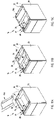
- FIG. 11A is a perspective view of the pedestal system and the hanger bracket and a first step of assembly thereof;
- FIG. 11B is a perspective view of the pedestal system and the hanger bracket and a second step of assembly thereof;
- FIG. 11C is a perspective view of the pedestal system and the hanger bracket and a third step of assembly thereof;
- FIG. 11D is a side view of the pedestal system being assembled with the worksurface, wherein rear support arms of the hanger bracket is slidably received within a first support bracket;
- FIG. 11E is a side view of the pedestal system being assembled with the worksurface, wherein a forward portion of the hanger bracket is coupled with a second support beam;
- FIG. 12 is an exploded rear perspective view of the drawer assembly
- FIG. 13 is a rear perspective view of a face plate assembled with a front wall of the drawer assembly
- FIG. 14 is a perspective view of the drawer divider supported within the drawer assembly
- FIG. 15 is a front cross-sectional view of the drawer divider located within the drawer assembly
- FIG. 16 is a front view of a hanger member of the drawer divider
- FIG. 17 is a side view of the hanger member
- FIG. 18 is a front perspective view of a lock/interlock assembly supported within the housing
- FIG. 19 is a side view of the lock/interlock assembly
- FIG. 20 is a side view of a cam lifter of the lock/interlock assembly
- FIG. 21 is a top view of the cam lifter
- FIG. 22 is a side view of a stop member of the lock/interlock assembly
- FIG. 23 is a top view of the stop member
- FIG. 24 is an enlarged front perspective view of a top connector of the lock/interlock assembly mounted within the housing;
- FIG. 25 is an enlarged rear perspective view of the top connector mounted within the housing
- FIG. 26 is an enlarged front perspective view of a bottom connector of the lock/interlock assembly mounted within the housing;
- FIG. 27 is an enlarged rear perspective view of the bottom connector mounted within the housing
- FIG. 28 is a top cross-sectional view of the lock actuator mounted within the housing
- FIG. 29 is a front cross-sectional view of the actuator mounted within the housing
- FIG. 30 is an end cross-sectional view of the lock actuator mounted within the housing.
- FIG. 31 is a top cross-sectional perspective view of the lock actuator connected to the lock/interlock assembly.
- the terms “upper,” “lower,” “right,” “left,” “rear,” “front,” “vertical,” “horizontal,” and derivatives thereof shall relate to the invention as oriented in FIG. 1 .
- the invention may assume various alternative orientations and step sequences, except where expressly specified to the contrary.
- the specific devices and processes illustrated in the attached drawings, and described in the following specification are exemplary embodiments of the inventive concepts defined in the appended claims. Hence, specific dimensions and other physical characteristics relating to the embodiments disclosed herein are not to be considered as limiting, unless the claims expressly state otherwise.
- the reference numeral 10 generally designates a furniture system ( FIG. 1 ) that includes a plurality of partition panels 12 and a plurality of worksurfaces 14 supported by a plurality of pedestal systems 16 . As illustrated, the pedestal systems 16 are configured so as to be coupled with the partition panels 12 and/or the associated worksurfaces 14 .
- Each pedestal system 16 ( FIG. 2 ) includes a housing 17 having a bottom wall 18 , a pair of sidewalls 20 extending upwardly from and opposed across the bottom wall 18 from one another, and a rear wall 22 extending upwardly from the bottom wall 18 and between the sidewalls 20 .
- the bottom wall 18 , sidewalls 20 and rear wall 22 cooperate with one another to define an interior space 24 and a forwardly-facing front opening 26 providing access to the interior space 24 .
- a lip 28 extends about an uppermost periphery of the sidewalls 20 and rear wall 22 and includes a pair of flanges 30 extending inwardly from each sidewall 20 , a flange 32 extending forwardly from the rear wall 22 , a rear structural member 34 extending between the sidewalls 20 proximate the flange 32 of the rear wall 22 , and a front structural member 36 extending between the sidewalls 20 and located forwardly of the rear structural member 34 .
- Each pedestal system 16 further includes a plurality of drawer assemblies 38 slidable supported within the housing 17 by drawer supports 40 located on opposite sides of each drawer assembly 38 . The drawer supports 40 allow each drawer assembly 38 to be moved from between a storage position A ( FIG.
- each drawer assembly 38 is slidably supported by a pair of drawer supports 40 each including a track member 41 affixed to an interior surface 21 of the associated sidewall 20 , at least one first slide member 42 slidably coupled with the track member 41 , and a second slide member 43 affixed to the associated drawer assembly 38 and slidably coupled with the first slide member 42 , in a manner as known in the art.
- the second slide member 43 is coupled with the first slide member 42 in a manner that allows separation therebetween, thereby allowing the associated drawer assembly 38 to be completely removed from within the interior space 24 of the housing 17 , as is further known in the art.
- the partition assembly 12 includes a plurality of partition panels 46 supported between a plurality of support posts 48 .
- Each support post 48 includes a cover member 50 covering a post member 52 ( FIG. 4 ) therein.
- Each post member 52 includes a forward surface 54 and a rearward surface 56 each including a plurality of longitudinally-extending and aligned slots 58 .
- Each cover member 50 includes longitudinally-extending channels 60 that align with and provide access to the slots 58 when the cover member 50 is assembled about the associated post member 52 .
- each pedestal system 16 is coupled with a post member 52 of the partition assembly 12 by a coupling assembly 62 .
- the coupling assembly 62 includes an L-shaped first mounting bracket 64 having an elongated, planar body portion 66 and a coupling flange 68 extending orthogonally and rearwardly from the body portion 66 .
- the body portion 66 includes a plurality of apertures 67 extending therethrough.
- the coupling flange 68 includes a plurality of rearwardly-extending T-shaped tabs 70 extending along the length of the first mounting bracket 64 .
- the coupling assembly 62 further includes a second mounting bracket 72 having a planar body portion 74 , a coupling flange 76 extending rearwardly from and orthogonally to the body portion 74 , a top flange 78 located near an end of the body portion 74 and extending laterally across and orthogonally thereto, and a bottom flange 79 located near an end of the body portion 74 opposite the flange 78 , and extending across and orthogonal to the body portion 74 .
- the body portion 74 includes a plurality of apertures 80 extending therethrough.
- the coupling flange 76 includes a plurality of rearwardly-extending, T-shaped tabs 82 extending along the length thereof.
- the first mounting bracket 64 is secured to a rear surface 23 of the rear wall 22 by a plurality of mechanical fasteners such as machine screws 84 that are received within the apertures 67 of the first mounting bracket 64 and are self-tapped into the rear wall 22 of the housing 17 , such that the body portion 66 of the first mounting bracket 64 abuts the rear surface 23 of the rear wall 22 and is securely fastened thereto.
- the second mounting bracket 72 is then aligned with the first mounting bracket 64 such that the body portion 74 of the second mounting bracket 72 abuts the body portion 66 of the first mounting bracket 64 and the flange 78 of the second mounting bracket 72 is closely aligned with an end 86 of the first mounting bracket 64 .
- the second mounting bracket 72 is then used as a template for marking the location of the apertures 80 of the second mounting bracket 72 onto the body portion 66 of the first mounting bracket 64 .
- the second mounting bracket 72 is then removed and holes 87 are drilled through the body portion 66 of the first mounting bracket 64 and the rear wall 22 of the housing 17 at the locations as marked and corresponding to the apertures 80 of the second mounting bracket 72 .
- the second mounting bracket 72 ( FIG. 5A ) is then assembled with the post member 52 by inserting the tabs 82 of the second mounting bracket 72 into the slots 58 of the post member 52 .
- the first mounting bracket 64 along with the associated housing 17 , is then positioned such that the tabs 70 of the first mounting bracket 64 engage the slots 58 of the post member 52 , and the rear wall 22 of the housing 17 is located proximate the associated partition panel 46 .
- the flange 78 of the second mounting bracket 72 is then grasped, either by hand or by use of a tool, and moved upwardly in a direction as indicated and represented by directional arrow 88 ( FIG. 5B ), such that the tabs 82 of the second mounting bracket 72 and the tab 70 of the first mounting bracket 64 engage the slots 58 of the post member 52 , thereby securely coupling the pedestal system 16 to the partition assembly 12 .
- a plurality of mechanical fasteners such as screws 88 are then used to secure the second mounting bracket 72 in place by accessing the apertures 87 of the rear wall 82 and first mounting bracket 64 and the apertures 80 of the second mounting bracket 72 through the interior space 24 of the housing 17 .
- a coupling assembly 90 is utilized to couple the housing 17 of the associated pedestal system 16 to the partition assembly 12 .
- the coupling assembly 90 includes a first mounting bracket 92 , a second mounting bracket 94 , and a wedge 96 .
- the first mounting bracket 92 is L-shaped and includes a planar body portion 98 and a coupling flange 100 extending rearwardly from and orthogonally to the body portion 98 .
- the body portion 98 includes a plurality of apertures 99 extending therethrough.
- the first mounting bracket 92 further includes a plurality of T-shaped tabs 102 spaced along the length of and extending rearwardly from the coupling flange 100 .
- the second mounting bracket 94 is L-shaped and includes a body portion 104 having a pair of laterally-extending slots 106 , and a coupling flange 108 extending rearwardly from and orthogonally to the body portion 104 .
- the coupling flange 108 includes a pair of rearwardly-facing, rectangularly-shaped, spaced-apart tabs 110 .
- the tabs 110 are each provided with a width that is only slightly less than the length of each slot 58 of the post member 52 .
- the wedge member 96 is U-shaped and includes a centrally disposed slot 112 .
- the first mounting bracket 22 is affixed to the rear wall 22 of the housing 17 by a plurality of mechanical fasteners such as screws 114 that are received within the apertures 99 of the first mounting bracket 92 and are self-tapped into the rear wall 22 of the housing 17 , such that the body portion 98 of the first mounting bracket 92 abuts and is securely fastened to the rear surface 23 of the rear wall 22 .
- a pair of screws 116 are extended through the slots 106 and secured into a weld nut 118 such that the second mounting bracket 94 is still allowed to float along a length of the screws 116 .
- the second mounting bracket 94 is then assembled with the associated post member 52 by inserting the tabs 110 of the second mounting bracket 94 into the slots 58 of the post member 52 , and is held in place until the first mounting bracket 92 and the housing 17 are moved into position.
- the first mounting bracket 92 and the housing 17 are moved into position such that the tabs 102 of the first mounting bracket 92 are received within the slots 58 of the post member 52 and the second mounting bracket 94 is trapped between the first mounting bracket 92 and the post member 52 .
- the housing 17 and the first mounting bracket 92 In order to properly position the first mounting bracket 92 and the housing 17 with respect to the post member 52 , the housing 17 and the first mounting bracket 92 must be elevated with respect to the post member, moved rearwardly until the tabs 102 of the first mounting bracket 92 are received within the slots 58 of the post member 52 , and lowered with respect to the post member 52 , such that the tabs 102 of the first mounting bracket 92 engage the slots 58 of the post member 52 . It should be noted that the second mounting bracket 94 is allowed to float along a length of the screws 116 at this point during the assembly.
- the second mounting bracket 94 is then secured into position by inserting the wedge member 96 between the body portion 98 of the first mounting bracket 92 and the body portion 104 of the second mounting bracket 94 , and such that the weld nut 118 is received into the slot 112 of the wedge member 96 , thereby preventing the second mounting bracket 94 from sliding along a length of the screws 116 and forcing the tabs 110 of the second mounting bracket 94 to remain engaged into the slots 58 of the post member 52 , thereby preventing dislodgement of the tabs 102 of the first mounting bracket 92 from within the slots 58 of the post member 52 .
- the pedestal system 16 may be hangingly supported from an associated worksurface 14 .
- the worksurface 14 includes a top surface 120 , a bottom surface 122 , ends 124 , a front edge 126 , and a rear edge 128 .
- the worksurface 14 ( FIG. 1 ) may be supported at either end 124 by an end wall 130 extending between the floor and the associated end 124 to which the end wall 130 is secured, a pedestal system 16 , or may be secured to the partition assembly 12 along the rear edge 128 of the worksurface 14 in a manner as is known in the art.
- a first support bracket 132 is affixed to the bottom surface 122 of the worksurface 14 and extends longitudinally therealong proximate the rear edge 128 .
- the first support bracket 132 ( FIG. 11D ) includes a plurality of slots 134 extending along the length thereof.
- a second support bracket 140 extends longitudinally along and is affixed to the bottom surface 122 of the worksurface 14 .
- the second support bracket 140 includes a plurality of apertures 142 spaced along the length thereof.
- connection plate 144 is positioned between the worksurface 14 and the pedestal system 16 and supports the pedestal system 16 from the worksurface 14 .
- the connection plate 144 ( FIGS. 9 and 10 ) includes a planar body portion 146 having a pair of support arms 148 extending laterally outwardly and rearwardly therefrom. Each support arm 148 includes an aperture 150 extending therethrough.
- the connection plate 144 also includes a planar engagement member 152 extending upwardly and rearwardly from the body portion 146 , thereby forming a gap 154 between the engagement member 152 and the support arms 148 of the body portion 146 .
- the engagement member 152 extends laterally across the body portion 146 and includes a pair of rearwardly-extending tab members 156 each including an upwardly-turned tip 158 .
- the connection plate 144 further includes a planar forward portion 160 extending forwardly from the body portion 146 and that includes a pair of laterally outwardly extending tabs 162 , and a plurality of apertures 164 extending therethrough.
- the forward portion 160 is upwardly offset from the body portion 146 .
- the support arms 148 of the body portion 146 and the tabs 162 of the forward portion 160 are configured so as to provide an offset or relief 166 therebetween.
- connection plate 144 In assembly, as best illustrated in FIGS. 11A-11E , the connection plate 144 is placed in a substantially vertical position with respect to the pedestal assembly 16 and is lowered and rotated in position such that the flanges 30 of each sidewall 20 are received within the reliefs 166 of the connection plate 144 ( FIG. 11A ). The connection plate 144 is then vertically and horizontally rotated such that the flanges 30 of the sidewalls 20 are positioned between the support arms 148 and the tabs 162 of the connection plate 144 ( FIG. 11B ). The connection plate 144 is then slid rearwardly until the rear structural member 34 is located within the gap 154 of the connection plate 144 and between the support arms 148 and the engagement member 152 ( FIG. 11C ).
- connection plate 144 is then secured to the pedestal system 16 by a plurality of mechanical fasteners such as screws 168 that extend through apertures 35 of the rear structural member 34 and into the apertures 150 of the connection plate 144 .
- the pedestal system 16 and the connection plate 144 are positioned beneath the worksurface 114 such that the support flange 138 of the first support bracket 132 is received into the gap 154 between the engagement member 152 and the support arms 148 of the connection plate 144 ( FIG. 11D ).
- the pedestal system 16 is then rotated upwardly until the forward portion 160 of the connection plate 144 is proximate the second support bracket 140 , and mechanical fasteners such as screws 170 are inserted into the apertures 164 of the connection plate 144 and are received within the apertures 142 of the second mounting bracket 140 , thereby securely fastening the connection plate 144 to the bottom surface 122 of the worksurface 14 and supporting the pedestal system 16 from the worksurface 14 ( FIG. 11E ).
- a third mounting bracket 171 ( FIGS. 11D and 11E ) is secured to the bottom 122 of the worksurface 14 proximate the front edge 126 .
- a plurality of screws 173 are then used to secure the pedestal system 16 to the worksurface 14 by extending the screw 173 through the front structural member 36 and into the third mounting bracket 171 .
- Each drawer assembly 38 ( FIG. 12 ) includes a bottom wall 172 integrally formed with a pair of sidewalls 174 that extend orthogonally upwardly from and are opposed across the bottom wall 172 from one another, a rear wall 176 that extends orthogonally upwardly from the bottom wall 172 and between the sidewalls 174 , a front wall 178 that extends orthogonally upwardly from the bottom wall 172 and between the sidewalls 174 , and a face plate 180 that is operably coupled with the front wall 178 .
- the bottom wall 172 includes a plurality of centrally-located, laterally-extending and longitudinally-aligned slots 182 extending therethrough.
- Each sidewall 174 includes an integrally formed and longitudinally-extending rail 184 located along an upper edge thereof.
- Each rail 184 includes a plurality of apertures 186 spaced along the length thereof.
- a drawer actuator pin 189 is fixedly connected to and extends outwardly from one of the sidewalls 174 .
- the rear wall 176 includes a rail 188 extending along the length thereof and located proximate an uppermost edge thereof.
- the rear wall 176 further includes a bottom flange 190 and a pair of side flanges 192 that are affixed to the bottom wall 172 and the sidewalls 174 by spot welding, thereby affixing the rear wall 176 with the bottom wall 172 and sidewalls 174 , respectively.
- the front wall 178 is rectangularly-box shaped and includes a rear surface 194 , and a pair of side surfaces 196 , a top surface 198 and a bottom surface 200 each extending forwardly from and orthogonally to the rear surface 194 .
- the front wall 178 is formed of a single piece of shaped sheet metal, however, other materials suitable for such application may be substituted therefore.
- the side surfaces 196 and the bottom surface 200 of the front wall 178 are secured to the sidewalls 174 and the bottom wall 172 of the drawer assembly 38 , respectively, by way of spot welding, and the like.
- the front wall 178 further includes a pair of upwardly-disposed hook members 202 extending forwardly from and integrally formed with the side surfaces 196 .
- the hook members 202 are located proximate the bottom surface 200 of the front wall 178 .
- the front wall 178 further includes a plurality of laterally and upwardly-extending tabs 204 integrally formed with the top surface 198 .
- the tabs 204 are laterally spaced across the front wall 178 so as to define gaps 206 therebetween. Each gap 206 is partially defined by a recess 208 extending rearwardly from the tabs 204 and into the top surface 198 .
- the tabs 204 cooperate to form a flange 210 extending laterally across an upper edge of the front wall 178 .
- the top surface 198 of the front wall 178 further includes a laterally-extending slot 212 for receiving the actuator arm 214 of a lock mechanism therethrough, as discussed below.
- the face plate 180 includes an aesthetic front surface 218 , a stepped top surface 220 , stepped side surfaces 222 and a bottom surface 224 .
- the front surface 218 is provided with an aesthetic cover of paint, fabric, or other finish as desired by the end user.
- the top surface 220 includes a first section 226 extending rearwardly from and orthogonally to the front surface 218 , a step section 228 extending downwardly from and orthogonal to the first section 226 , and a second section 230 extending rearwardly from and orthogonally to the step section 228 .
- a laterally-extending flange 232 is integrally formed with the second section 230 and extends downwardly from and orthogonally to the second section 230 .
- the flange 232 includes a pair of downwardly-extending and spaced-apart tabs 234 each having tapered sidewalls 236 .
- the tabs 234 are located so as to align with the gaps 206 and the recesses 208 of the front wall 178 , as described below.
- Each side surfaces 222 includes a first section 238 extending rearwardly from and orthogonally to the front surface 218 , a step section 240 extending inwardly from and orthogonally to the first section 238 , a second section 242 extending rearwardly from and orthogonally to the first step section 240 , and a second step section 244 extending inwardly from and orthogonally to the second section 242 .
- An L-shaped tab member 246 is integrally formed with and extends inwardly from an orthogonal to the second step section 244 .
- the tab member 246 includes a first portion 248 that is substantially planar with the second step section 244 and that includes an abutment wall 250 along the lower edge thereof, and a second portion 252 extending orthogonally to and rearwardly from the first portion 248 and having a plurality of apertures 254 spaced therealong.
- a flange 256 extends longitudinally along, upwardly from and orthogonally to the bottom surface 224 .
- the face plate 180 ( FIGS. 12 and 13 ) is aligned with the sidewalls 174 of the drawer assembly 38 , such that the second portion 252 of each tab member 246 is located inwardly of the side surfaces 196 of the front wall 178 , and further such that the abutment wall 250 of each tab member 246 is located upwardly from the hook members 202 .
- the face plate 180 is then moved inwardly toward the front wall 178 until the tabs 234 are vertically aligned with the gaps 206 and the recesses 208 of the front wall 178 .
- the face place 180 is then lowered with respect to the front wall 178 until the tabs 234 are received within the gaps 206 and the recesses 208 of the front wall 178 , the tabs 204 of the front wall 178 are located in front of the flange 232 of the face plate 180 , and the abutment walls 250 are received within the hook members 202 , thereby coupling the face plate 180 with the front wall 178 .
- a plurality of screws 253 are then placed through apertures 187 of the sidewalls 174 and are threadably received into apertures 254 of the face plate 180 , thereby securely fastening the face plate 180 to the front wall 178 .
- a drawer divider 260 ( FIGS. 2 and 14 ) is provided to subdivide the interior space 44 of each drawer assembly 38 .
- the drawer divider 260 includes a planar body portion 262 having a top edge 264 , a bottom edge 266 and side edges 268 .
- the bottom edge 266 includes a centrally-located and downwardly-extending tab 270 .
- a notch 274 extends inwardly from each side edge 268 , thereby defining a tab 276 on each side of the body portion 262 .
- Each tab 276 includes an aperture 272 extending therethrough.
- the drawer divider 260 further includes a pair of hook-shaped engagement or hanger members 278 ( FIGS.
- a pair of inwardly-extending tabs 283 are located within the pocket 282 of the sleeve 280 and engage the apertures 277 of the tabs 276 .
- the hook-shaped portion 284 includes a flexibly resilient and outwardly-extending arm portion 286 having a knob 288 located at an end thereof.
- Each hanger member 278 includes a semi-circularly shaped tab 290 extending outwardly towards the arm portion 286 .
- the drawer divider 260 is placed within the interior space 44 of the drawer assembly 38 such that the tab 270 is received within one of the slots 182 of the bottom wall 172 , and further such that the tabs 290 are received within corresponding apertures 186 of the sidewalls 174 , thereby positively locating the drawer divider 260 within the drawer assembly 38 and subdividing the interior space 44 .
- the simultaneous engagement of the bottom tab 270 and the side tabs 290 with the drawer assembly 38 prevents any tipping or rotation of the divider 260 with respect to the drawer assembly 38 .
- the arm portions 286 of the hanger members 278 bias the knobs 288 into engagement with the rails 184 of the sidewalls 174 and the tabs 290 into engagement within the apertures 186 of the sidewalls 174 .
- the pedestal system 16 further includes a lock/interlock system 292 ( FIGS. 18 and 19 ) for locking the drawer assemblies 38 in a closed position, as well as for interlocking the actuation of the drawer assemblies 38 to one another.
- the lock/interlock system 292 includes a lock/interlock assembly 294 secured to the interior surface 21 of at least one of the sidewalls 20 .
- the lock/interlock 294 includes a guide member 296 having a longitudinally-extending C-shaped channel 298 having a finite operable length, a plurality of cam assemblies 300 slidably coupled with the channel 298 , a plurality of stop members 302 slidably coupled with the channel 298 and interspaced with the cam assemblies 300 , and a plurality of lift bars 304 slidably received within the channel 298 and interspaced with the cam assemblies 300 and the stop members 302 .
- Each cam assembly 300 ( FIGS. 20 and 21 ) includes a slide member 306 , and a cam member 308 pivotally coupled to the slide member 306 at a pivot point 310 .
- the slide member 306 includes a main body portion 312 having an arcuately-shaped leading edge 314 , and a T-shaped slide portion 316 that is slidably received within the channel 298 .
- the cam member 308 includes a first cam surface 317 and a second cam surface 318 divided by a pin receiving, arcuately-shaped pocket 320 , and wherein the distance between the second cam surface 318 and the pivot point 310 is greater than the distance between the first cam surface 317 and the pivot point 310 . It should be noted that the radius of the curve formed by the leading edge 314 remains constant with respect to the pivot point 310 .
- Each stop member 302 ( FIGS. 22 and 23 ) includes a first abutment surface 322 having a recess 323 , a second abutment surface 324 angled with respect to the first abutment surface 322 , and a bottom surface 326 .
- Each stop member 302 further includes a rearwardly-extending T-shaped slide portion 328 slidably received within the channel 298 .
- each cam assembly 300 abuts the second abutment surface 324 of the associated stop member 302 when the corresponding drawer assembly is in the closed position.
- a coil spring 330 is located within the channel 298 at an uppermost portion thereof, and functions to resiliently force the cam assemblies 300 , stop members 302 and lift bars 304 downwardly within the guide member 296 .
- the slide portion 316 of the slide member 306 abuts the lift bar or rod 304 located directly above, which in turn acts on any stop member 302 and cam assembly 300 located above that point.
- the cam assemblies 300 , stop members 302 and lift bars 304 located above the lift point are allowed to move upwardly closing the gap 334 as defined between a first stop member 336 slidably received within the channel 298 , and a second stop member 338 fixedly received within an end of the channel 298 . Subsequent opening of additional drawer assemblies 38 is prevented as the gap 334 is completely closed by the opening of the first drawer assembly 338 and the resulting movement of the associated lock/interlock assembly 294 , thereby prohibiting the movement of any additional cam assemblies 300 .
- An attachment assembly for mounting the lock/interlock system 292 within the interior space 24 of the housing 17 includes a top connector member 340 ( FIGS. 24 and 25 ) having a body portion 342 , a pair of rearwardly-disposed channels 344 for receiving the guide member 296 therein, a pair of downwardly-extending legs 346 that guide along the edge of the guide member 296 , a rearwardly-extending L-shaped first tab 348 , and a rearwardly-extending second tab 350 spaced apart from the first tab 348 .
- the top connector member 340 further includes a forwardly-extending guide arm 349 having an upwardly-extending prong 351 located at a distal end thereof.
- the attachment assembly further includes a rectangularly-shaped bottom connector member 352 ( FIGS. 26 and 27 ) having a pair of channels 354 extending therethrough for receiving the guide member 296 therein.
- the bottom connector member 352 also includes a pair of downwardly-opening, rearwardly-extending and laterally-spaced hooks 3
- a hat-shaped upright 357 is attached to the interior surface 21 of one of the sidewalls 20 by way of welding, an adhesive or the like.
- the upright 357 includes a first laterally-extending, rectangularly-shaped aperture 360 located near an upper end thereof, and a pair of laterally spaced-apart square-shaped apertures 362 located near a lower end thereof.
- the bottom connector member 352 is coupled with the upright 357 by inserting the hooks 356 into the apertures 362 .
- the lower end of the guide member 296 of the lock/interlock system 292 is then placed within the channels 354 of the bottom connector member 352 .
- the top connector member 340 is then aligned with the top of the guide member 296 of the lock/interlock system 292 , and the guide member 296 is slightly rotated such that the first tab 348 of the top connector member 340 can be inserted into the aperture 360 of the upright 358 .
- the guide member 296 is rotated and pressed inwardly toward the upright 357 , such that the second tab 350 is closely received within the aperture 360 , thereby preventing disengagement of the first tab 348 from within the aperture 360 and securely coupling the lock/interlock system 292 within the interior space 24 of the housing 17 .
- the lock mechanism 216 ( FIGS. 12 ) includes a key-actuated tumbler assembly 364 mounted within the face plate 180 and in operable communication with the actuator arm 214 .
- the actuator arm 214 is received within a slot 366 of a locking arm 368 that is slidably coupled within the front structural member 36 of the housing 17 .
- the locking arm 368 ( FIGS. 28-31 ) includes a body portion 370 having a forwardly-extending channel 376 , and an upwardly-extending, inverted V-shaped, flexibly resilient prong 378 having a free end 380 .
- the locking arm 368 is slidably coupled with the C-shaped front structural member 36 by locating the channel 376 of the locking arm 368 about a first channel 382 of the front structural member 36 and pressing the locking arm 368 upwardly toward the front structural member 36 , thereby forcing the prong 378 past a second flange 384 of the front structural member 36 .
- the locking arm 368 further includes a rearwardly-extending, triangularly-shaped arm 386 , a spring receiver 388 extending outwardly from the arm 386 , and a coupling loop 390 .
- the spring receiver 388 receives a coil spring 392 thereabout that is biased between the arm 386 and the associated sidewall 20 of the housing 17 , thereby biasing the locking arm 368 toward an unlocked position.
- the coupling loop 390 includes a retention member 394 and a stop member 396 that cooperate to form a broken loop. In assembly, the guide arm 349 of the top connector member 340 is slidably received within the coupling loop 390 such that the retention member 394 extends above the guide arm 349 and the stop member 396 is located below the guide arm 349 .
- the tumbler assembly 364 is key-actuated between a locked position, and an unlocked position.
- the actuator arm 214 rotates in a clockwise direction about the tumbler assembly 364 and forces the locking arm 368 to slide overcoming the biasing force as exerted thereon by the coil spring 392 and such that the stop member 396 of the locking arm 368 is located within the gap 334 of the lock/interlock system 292 , thereby preventing any of the components of the lock/interlock assembly 294 from sliding within the guide member 296 and effectively locking each and every drawer assembly 38 in the closed position within the housing 17 .
- the tumbler assembly In an unlocked position the tumbler assembly is key-actuated in a clockwise direction, such that the biasing force of the coil spring 392 biases the locking arm 368 in a direction away from the lock/interlock system 292 , thereby removing the stop member 396 from within the gap 334 an allowing the drawer assemblies 38 to be moved to the open position.
- the present inventive pedestal system includes assemblies and subsystems that may be utilized within a wide variety of storage systems, are relatively inexpensive to manufacture, and may be assembled/disassembled without the use of specialized tools and/or skilled personnel. Moreover, the pedestal system disclosed herein are efficient in assembly/disassembly as well as in use, is capable of a long-operating life, and is particularly well adapted for the proposed use.
Landscapes
- Drawers Of Furniture (AREA)
Abstract
Description
Claims (26)
Priority Applications (2)
| Application Number | Priority Date | Filing Date | Title |
|---|---|---|---|
| US10/804,717 US7469979B2 (en) | 2004-03-19 | 2004-03-19 | Pedestal system |
| US12/332,813 US20090091228A1 (en) | 2004-03-19 | 2008-12-11 | Pedestal system |
Applications Claiming Priority (1)
| Application Number | Priority Date | Filing Date | Title |
|---|---|---|---|
| US10/804,717 US7469979B2 (en) | 2004-03-19 | 2004-03-19 | Pedestal system |
Related Child Applications (1)
| Application Number | Title | Priority Date | Filing Date |
|---|---|---|---|
| US12/332,813 Division US20090091228A1 (en) | 2004-03-19 | 2008-12-11 | Pedestal system |
Publications (2)
| Publication Number | Publication Date |
|---|---|
| US20050204646A1 US20050204646A1 (en) | 2005-09-22 |
| US7469979B2 true US7469979B2 (en) | 2008-12-30 |
Family
ID=34984652
Family Applications (2)
| Application Number | Title | Priority Date | Filing Date |
|---|---|---|---|
| US10/804,717 Expired - Lifetime US7469979B2 (en) | 2004-03-19 | 2004-03-19 | Pedestal system |
| US12/332,813 Abandoned US20090091228A1 (en) | 2004-03-19 | 2008-12-11 | Pedestal system |
Family Applications After (1)
| Application Number | Title | Priority Date | Filing Date |
|---|---|---|---|
| US12/332,813 Abandoned US20090091228A1 (en) | 2004-03-19 | 2008-12-11 | Pedestal system |
Country Status (1)
| Country | Link |
|---|---|
| US (2) | US7469979B2 (en) |
Cited By (11)
| Publication number | Priority date | Publication date | Assignee | Title |
|---|---|---|---|---|
| US20070159800A1 (en) * | 2006-01-10 | 2007-07-12 | Funai Electric Co., Ltd. | Cabinet for electric apparatus |
| US20090091226A1 (en) * | 2006-01-19 | 2009-04-09 | Youngs Bradley D | Storage cabinet assembly |
| US20100066224A1 (en) * | 2007-02-06 | 2010-03-18 | Bsh Bosch Und Siemens Hausgerate Gmbh | Telescopic pull-out arrangement |
| USD625941S1 (en) * | 2008-02-22 | 2010-10-26 | Julius Blum Gmbh | Front plate |
| US20110095667A1 (en) * | 2009-10-27 | 2011-04-28 | Jamie Toland | Desk drawer face converter module |
| US8919264B1 (en) | 2014-04-08 | 2014-12-30 | WL Innovations, LLC | Work surface height adjustor with universal mount |
| US9206827B2 (en) | 2012-11-20 | 2015-12-08 | Avery Dennison Corporation | Wall mount organization system |
| US20220151385A1 (en) * | 2020-11-13 | 2022-05-19 | InnovaShelf LLC | Floating fixture wall mount system and method of use |
| US20220175137A1 (en) * | 2020-12-09 | 2022-06-09 | Grass Gmbh | Furniture drawer |
| US11653761B2 (en) * | 2019-08-15 | 2023-05-23 | Bsh Home Appliances Corporation | Removable appliance door with repeatable alignment |
| TWI842394B (en) * | 2023-02-14 | 2024-05-11 | 川湖科技股份有限公司 | Slide rail mechanism |
Families Citing this family (29)
| Publication number | Priority date | Publication date | Assignee | Title |
|---|---|---|---|---|
| US7784887B2 (en) * | 2007-03-21 | 2010-08-31 | Larry Mitchell Grela | Toolbox assembly |
| US8104850B2 (en) | 2007-05-30 | 2012-01-31 | Steelcase Inc. | Furniture storage unit |
| US20090102337A1 (en) * | 2007-10-17 | 2009-04-23 | Larry Mitchell Grela | Side cabinet and hutch system |
| US8827387B2 (en) | 2007-10-17 | 2014-09-09 | Larry Mitchell Grela | Side cabinet and hutch system |
| US20100072716A1 (en) * | 2008-09-19 | 2010-03-25 | Larry Mitchell Grela | Portable tool storage assembly |
| US8157337B2 (en) | 2009-06-16 | 2012-04-17 | Edwin Dizon Manalang | Tool box storage assembly |
| US9630312B2 (en) | 2009-06-16 | 2017-04-25 | Larry Mitchell Grela | Tool box storage assembly |
| USD649377S1 (en) | 2009-06-17 | 2011-11-29 | Larry Mitchell Grela | Storage assembly |
| USD677934S1 (en) | 2010-09-21 | 2013-03-19 | Larry Mitchell Grela | Toolbox |
| AT511091B1 (en) * | 2011-04-19 | 2012-09-15 | Blum Gmbh Julius | DRAWER WHEEL WITH TILT ADJUSTMENT |
| USD678694S1 (en) | 2011-06-08 | 2013-03-26 | Larry Mitchell Grela | Tool box |
| US8613456B2 (en) | 2011-10-11 | 2013-12-24 | Larry Mitchell Grela | Toolbox assembly |
| CN103455110A (en) * | 2012-06-01 | 2013-12-18 | 鸿富锦精密工业(深圳)有限公司 | Server tray |
| US9388609B2 (en) | 2013-10-17 | 2016-07-12 | Larry Mitchell Grela | Drawer latch assembly and toolbox assembly |
| US9181731B2 (en) | 2013-10-17 | 2015-11-10 | Larry Mitchell Grela | Drawer latch assembly and a toolbox assembly |
| US8944537B1 (en) | 2013-10-17 | 2015-02-03 | Edwin Dizon Manalang | Drawer latch assembly a toolbox assembly |
| CN110177290B (en) | 2014-04-27 | 2021-10-26 | Lg电子株式会社 | Method and apparatus for transmitting or receiving service guide fragments |
| USD747875S1 (en) | 2014-11-22 | 2016-01-26 | Edwin Dizon Manalang | Tool box |
| KR102468763B1 (en) * | 2016-02-05 | 2022-11-18 | 삼성전자 주식회사 | Image processing apparatus and control method thereof |
| US9894996B1 (en) | 2016-10-31 | 2018-02-20 | Larry Mitchell Grela | Cabinet |
| US10293478B2 (en) | 2017-06-06 | 2019-05-21 | Larry Mitchell Grela | Storage hutch assembly |
| USD869881S1 (en) | 2018-03-23 | 2019-12-17 | Hni Technologies Inc. | Undermount storage structure |
| US11006749B2 (en) | 2018-03-23 | 2021-05-18 | Hni Technologies Inc. | Systems, brackets, and methods for mounting storage structures to office work surfaces |
| US10954696B2 (en) | 2018-11-19 | 2021-03-23 | Larry Mitchell Grela | Storage assembly with a drawer having a drawer pull assembly and a method for locking a drawer |
| US11304507B2 (en) * | 2020-02-27 | 2022-04-19 | Jacob Atherton | Modular component desk system |
| USD1135384S1 (en) | 2024-05-17 | 2026-07-21 | Larry Mitchell Grela | Workstation or toolbox |
| USD1135383S1 (en) | 2024-05-17 | 2026-07-21 | Larry Mitchell Grela | Workstation or toolbox |
| USD1136582S1 (en) | 2024-05-17 | 2026-07-28 | Larry Mitchell Grela | Workstation or toolbox |
| USD1135385S1 (en) | 2024-05-17 | 2026-07-21 | Larry Mitchell Grela | Workstation or toolbox |
Citations (116)
| Publication number | Priority date | Publication date | Assignee | Title |
|---|---|---|---|---|
| US960833A (en) | 1908-03-06 | 1910-06-07 | Winfield S Crum | Delivery-basket. |
| US1136071A (en) | 1913-12-18 | 1915-04-20 | Yawman & Erbe Mfg Co | Metallic-furniture drawer. |
| US1172189A (en) | 1914-07-06 | 1916-02-15 | Art Metal Construction Co | Drawer-head. |
| US1222451A (en) * | 1912-10-28 | 1917-04-10 | U S Steel Furniture Company | Furniture-drawer. |
| US1352002A (en) | 1920-04-26 | 1920-09-07 | Emil J Jones | Knockdown sheet-metal drawer |
| US1649805A (en) | 1925-11-09 | 1927-11-22 | Gen Fireproofing Co | Metal desk construction |
| US1757293A (en) | 1925-12-17 | 1930-05-06 | Jamestown Metal Equipment Co I | Drawer |
| US1770836A (en) | 1928-09-24 | 1930-07-15 | Boote Charles | Filing device |
| US1906191A (en) | 1928-05-01 | 1933-04-25 | Thomas Bertram | Box and shelves and partitions therefor |
| US1933932A (en) | 1933-06-15 | 1933-11-07 | Standard School Fixtures Compa | Student desk |
| US2020373A (en) | 1934-02-05 | 1935-11-12 | Jr Ernst H Petzold | Baking pan |
| US2663449A (en) | 1951-11-06 | 1953-12-22 | Smart Dorothy Delle | Variable volume baking device |
| US3024075A (en) | 1958-08-13 | 1962-03-06 | Home O Nize Co | Removable drawer front |
| US3179480A (en) | 1963-03-04 | 1965-04-20 | Globe Wernicke Co Division Of | Filing drawer construction |
| US3273952A (en) * | 1964-07-14 | 1966-09-20 | H J Scheirich Company | Method of making furniture drawers or the like and article produced thereby |
| US3346311A (en) | 1966-04-04 | 1967-10-10 | Bears Waldo Whitman | Desk construction |
| US3358692A (en) | 1965-03-17 | 1967-12-19 | Visirecord Inc | Filing system |
| US3547300A (en) | 1969-04-22 | 1970-12-15 | Lyon Metal Product Inc | Extension plates for metal drawers and the like |
| US3565502A (en) | 1969-04-16 | 1971-02-23 | Blickman Inc | Cantilever mounted laboratory equipment module system |
| US3649095A (en) * | 1970-09-21 | 1972-03-14 | Art Lloyd Metal Products Corp | Pilfer-proof desk and work table drawer |
| US3650586A (en) | 1970-04-02 | 1972-03-21 | Paul Leslie Nightingale | Laboratory bench or table |
| US3705754A (en) * | 1970-02-16 | 1972-12-12 | Hon Ind Inc | Filing units |
| US3752553A (en) | 1971-07-29 | 1973-08-14 | Amerock Corp | Drawer with snap-on front panel |
| US3799638A (en) | 1972-08-17 | 1974-03-26 | Steelcase Inc | Drawer interlock |
| US3809449A (en) | 1970-10-15 | 1974-05-07 | All Steel Inc | Foundation framework for metal office furniture |
| US3838902A (en) | 1972-06-09 | 1974-10-01 | Interburo Holding | Easily assemblable furniture, such as a desk |
| US3857622A (en) | 1973-06-01 | 1974-12-31 | Steelcase Inc | Nd panel support system |
| US3862789A (en) | 1973-06-01 | 1975-01-28 | Steelcase Inc | Suspended pedestal desk |
| US3883196A (en) | 1973-06-01 | 1975-05-13 | Steelcase Inc | End panel support system |
| US3890023A (en) | 1973-06-01 | 1975-06-17 | Steelcase Inc | End panel support system |
| US3900236A (en) | 1974-06-28 | 1975-08-19 | Gf Business Equip | File interlock |
| US3909090A (en) | 1974-11-18 | 1975-09-30 | Gf Business Equip | Office appliance |
| US3920298A (en) | 1974-07-05 | 1975-11-18 | Camilo Muebles Inc | Convertible desk and secretarial return |
| US3933402A (en) | 1974-07-15 | 1976-01-20 | Joerns Furniture Company | Drawer with removable front panel |
| US4013254A (en) | 1976-01-07 | 1977-03-22 | Westinghouse Electric Corporation | Mounting clip lock |
| US4102470A (en) | 1977-01-28 | 1978-07-25 | Hiebert, Inc. | Drawer file folder stop |
| US4176889A (en) | 1978-06-30 | 1979-12-04 | Pleion Corporation | Modular storage unit assembly |
| US4239309A (en) | 1979-07-31 | 1980-12-16 | Lear Siegler, Inc. | Filing cabinet including drawer interlock |
| US4298236A (en) | 1980-07-14 | 1981-11-03 | Artopex Inc. | Safety lock system for vertically stacked storage elements |
| EP0058535A2 (en) | 1981-02-12 | 1982-08-25 | Arenson International Limited | Improvements in desks |
| US4355851A (en) | 1980-11-28 | 1982-10-26 | Herman Miller, Inc. | Drawer interlock system |
| US4429930A (en) | 1981-12-24 | 1984-02-07 | Nightingale Saro Inc. | Interlock for drawers |
| GB2071995B (en) | 1980-03-13 | 1984-02-22 | Vickers Ltd | Parts or assembling drawers and the like |
| US4441767A (en) | 1982-04-21 | 1984-04-10 | Avm Corporation | Cabinet drawer anti-tip lock device |
| US4480883A (en) | 1983-02-25 | 1984-11-06 | Office Specialty Division Of Hollanding Inc. | Anti-tip blocking device |
| US4541599A (en) | 1983-08-19 | 1985-09-17 | Westinghouse Electric Corp. | Self-locking mounting clip system |
| US4633789A (en) | 1984-08-17 | 1987-01-06 | Haworth, Inc. | Toolless mounting arrangement |
| US4637667A (en) | 1985-05-16 | 1987-01-20 | Joyce International, Inc. | Positive interlock for file cabinet |
| US4660905A (en) | 1984-06-13 | 1987-04-28 | Trendway Corporation | Modular storage units |
| US4671481A (en) | 1985-10-15 | 1987-06-09 | Herman Miller, Inc. | Antidislodgement clips |
| US4732430A (en) | 1987-02-26 | 1988-03-22 | Byrns James E | Blow molded drawer front |
| US4761045A (en) | 1987-05-22 | 1988-08-02 | Metalworks, Inc. | Drawer and cabinet assembly |
| US4768844A (en) | 1987-05-08 | 1988-09-06 | Hauserman, Inc. | Office cabinet |
| US4770476A (en) | 1987-06-05 | 1988-09-13 | Lakso Matthew L | Multiple drawer locking system |
| US4786119A (en) | 1987-12-23 | 1988-11-22 | Metalworks, Inc. | Locking clip for securing a bolt holding panel members together |
| US4815796A (en) | 1986-05-14 | 1989-03-28 | Julius Blum Gesellschaft M.B.H. | Drawer |
| US4830440A (en) | 1987-06-15 | 1989-05-16 | Haworth, Inc. | Tool-free cabinet attachment |
| US4865404A (en) | 1988-07-18 | 1989-09-12 | Harpers | Interlock for multi-drawer cabinet |
| US4889396A (en) | 1988-12-12 | 1989-12-26 | G. A. Richards Company | Drawer interlock |
| GB2199737B (en) | 1986-11-04 | 1990-03-07 | Abbott Brothers | Desks |
| US4936640A (en) | 1988-07-26 | 1990-06-26 | Pundra Industries Ltd. | Anti-tip mechanism and method for providing anti-tip device |
| US4957334A (en) | 1988-11-01 | 1990-09-18 | Priority Mfg. Corp. | Interlock system |
| US4966423A (en) | 1989-12-21 | 1990-10-30 | Russ Bassett Company | Cabinet drawer interlocking apparatus |
| US4971281A (en) | 1989-05-22 | 1990-11-20 | Hon Industries Inc. | Anti-dislodgement mechanism |
| US4993784A (en) | 1988-12-07 | 1991-02-19 | Engineered Security Products Corporation | Locking device |
| US5016946A (en) * | 1990-03-05 | 1991-05-21 | Innovative Concepts, Inc. | Modular storage container for diskettes |
| US5040858A (en) | 1988-07-05 | 1991-08-20 | Paul Hettich Gmbh & Co. | Mounting for furniture having superimposed drawers |
| US5040856A (en) * | 1987-02-27 | 1991-08-20 | Sub-Zero Freezer Company, Inc. | Comestible storage compartment for refrigeration unit |
| US5050942A (en) | 1987-08-11 | 1991-09-24 | Supreme Equipment And Systems Corp. | File interlock system |
| US5054255A (en) | 1989-10-27 | 1991-10-08 | Herbert Maninfior Design/Engineering | Wall panel construction and connection system |
| US5056876A (en) | 1988-11-29 | 1991-10-15 | Steelcase Inc. | Drawer lock and interlock mechanism |
| US5056877A (en) | 1990-05-08 | 1991-10-15 | Pundra Industries Limited | Locking anti-tip device |
| US5074627A (en) | 1990-07-13 | 1991-12-24 | Reff Incorporated | Anti-tilt and locking mechanism for multi-drawer cabinets |
| US5161870A (en) | 1991-08-30 | 1992-11-10 | Westinghouse Electric Corp. | File drawer having removable outer drawer head |
| US5176436A (en) | 1991-10-21 | 1993-01-05 | Quest Engineering, Ltd. | Strap type drawer interlock structure |
| US5184887A (en) | 1990-10-26 | 1993-02-09 | Herman Miller, Inc. | Drawer interlock system |
| US5199774A (en) | 1990-11-27 | 1993-04-06 | Kimball International, Inc. | Combination lock and interlock for a file cabinet |
| US5230492A (en) | 1991-10-01 | 1993-07-27 | Integrated Metal Technology, Inc. | Support bracket |
| US5303994A (en) | 1992-06-05 | 1994-04-19 | Steelcase Inc. | Drawer interlock |
| US5309686A (en) | 1992-02-19 | 1994-05-10 | Kimball International, Inc. | Work space partition system |
| US5312180A (en) | 1992-10-09 | 1994-05-17 | Steelcase Inc. | File drawer compressor |
| US5333949A (en) | 1992-10-05 | 1994-08-02 | Krueger International, Inc. | File drawer interlock mechanism |
| US5335986A (en) | 1993-01-08 | 1994-08-09 | Metalworks, Inc. | Interlock assembly |
| US5352030A (en) | 1992-09-11 | 1994-10-04 | Wolfgang Derle | Anti-tip device |
| US5427445A (en) | 1994-10-05 | 1995-06-27 | Quest Engineering | Drawer interlock structure |
| US5433516A (en) | 1987-03-24 | 1995-07-18 | Hon Industries, Inc. | Filing cabinets |
| US5437503A (en) | 1993-06-01 | 1995-08-01 | General Electric Company | Modular storage drawer assembly for use in a refrigerator |
| US5494246A (en) | 1994-06-17 | 1996-02-27 | Haworth, Inc. | Passive lock for end panel assembly |
| US5567027A (en) | 1993-06-11 | 1996-10-22 | Herman Miller, Inc. | Cabinet drawer lock |
| US5599077A (en) | 1994-02-25 | 1997-02-04 | Flexiform Business Furniture Limited | Cabinet locking system |
| US5599078A (en) | 1995-11-08 | 1997-02-04 | Alb Industries Ltd. | Anti-tip device for file cabinets |
| US5702167A (en) | 1994-12-20 | 1997-12-30 | Huwil-Werke Gmbh | Drawer locking means for drawers arranged one above the other |
| US5772294A (en) | 1994-08-31 | 1998-06-30 | Hendrich; Ronald D. | Multi-drawer cabinet having a drawer lock-out mechanism |
| US5823650A (en) | 1997-03-28 | 1998-10-20 | Lin; Tsung Lung | Drawer assembly |
| US5855423A (en) | 1998-02-11 | 1999-01-05 | Planhold Corporation | Flat file cabinet with drawer interlock |
| US5921648A (en) | 1997-12-31 | 1999-07-13 | Rong; Liu Ching | Drawer assembly for a storage bin |
| US5931548A (en) | 1997-02-18 | 1999-08-03 | Steelcase Inc. | Drawer interlock to non-interlock conversion device |
| US5951133A (en) | 1997-09-11 | 1999-09-14 | Dittberner; Daniel J. | Drawer head |
| US5988778A (en) | 1996-07-12 | 1999-11-23 | Accuride International, Inc. | Rod-based file interlock system |
| US6007170A (en) | 1997-10-02 | 1999-12-28 | Haworth, Inc. | Knock-down vertical file |
| US6050661A (en) | 1997-11-24 | 2000-04-18 | Alfit Aktiengesellschaft | Drawer |
| US6056380A (en) | 1999-08-30 | 2000-05-02 | Nien; Hsiu-Chung | Simplified assembly document drawer structure |
| US6082839A (en) | 1997-06-12 | 2000-07-04 | Inaba Saisakusho Co., Ltd | Drawer control for office cabinets |
| US6109708A (en) | 1998-11-23 | 2000-08-29 | Timberline Lock Ltd. | Locking mechanism for drawer system |
| US6112485A (en) | 1998-11-04 | 2000-09-05 | Haworth, Inc. | Post-panel connector arrangement |
| US6186606B1 (en) | 1998-10-17 | 2001-02-13 | The Marvel Group, Inc. | Lateral File Locking System |
| US6202965B1 (en) | 1998-12-21 | 2001-03-20 | The Marvel Group, Inc. | Panel fastening system for modular office furniture |
| US6312186B1 (en) | 1998-02-09 | 2001-11-06 | Julius Blum Gesellschaft M.B.H. | Fastening device |
| US20020014817A1 (en) | 1996-07-12 | 2002-02-07 | Lammens Arthur E. | File interlock system and mechanism |
| US6409293B1 (en) | 2001-07-24 | 2002-06-25 | Ching-Chang Chang | Cabinet and drawer assembly structure |
| US6419333B2 (en) | 1997-10-02 | 2002-07-16 | Haworth, Inc. | Knock-down vertical file |
| US6428129B1 (en) | 2001-08-03 | 2002-08-06 | Shun-Teng Chen | Cabinet |
| US6450596B1 (en) | 2000-10-26 | 2002-09-17 | Nan Juen Industrial Co., Ltd. | Interlocking device for drawers |
| US20020185943A1 (en) | 2001-06-01 | 2002-12-12 | Stefano Gentili | Drawer interlock |
| US6516507B2 (en) | 2001-06-15 | 2003-02-11 | Knoll, Inc. | Method of making a metal drawer head |
| US20030062810A1 (en) | 2001-10-03 | 2003-04-03 | Florian Westwinkel | Modular housing |
Family Cites Families (5)
| Publication number | Priority date | Publication date | Assignee | Title |
|---|---|---|---|---|
| US5325641A (en) * | 1992-02-03 | 1994-07-05 | T. J. Hale Company | System for mounting a wall panel |
| US5285602A (en) * | 1992-03-09 | 1994-02-15 | T. J. Hale Company | Modular wall system with "slideby" mounting feature |
| US5746034B1 (en) * | 1994-12-30 | 2000-10-17 | Steelcase Inc | Partition system |
| US6481678B1 (en) * | 1999-01-29 | 2002-11-19 | The Marvel Group, Inc. | Electrical housing for modular office furniture |
| US20020112411A1 (en) * | 2001-02-22 | 2002-08-22 | Gravel Donald P. | Bracket assembly for partition panels |
-
2004
- 2004-03-19 US US10/804,717 patent/US7469979B2/en not_active Expired - Lifetime
-
2008
- 2008-12-11 US US12/332,813 patent/US20090091228A1/en not_active Abandoned
Patent Citations (118)
| Publication number | Priority date | Publication date | Assignee | Title |
|---|---|---|---|---|
| US960833A (en) | 1908-03-06 | 1910-06-07 | Winfield S Crum | Delivery-basket. |
| US1222451A (en) * | 1912-10-28 | 1917-04-10 | U S Steel Furniture Company | Furniture-drawer. |
| US1136071A (en) | 1913-12-18 | 1915-04-20 | Yawman & Erbe Mfg Co | Metallic-furniture drawer. |
| US1172189A (en) | 1914-07-06 | 1916-02-15 | Art Metal Construction Co | Drawer-head. |
| US1352002A (en) | 1920-04-26 | 1920-09-07 | Emil J Jones | Knockdown sheet-metal drawer |
| US1649805A (en) | 1925-11-09 | 1927-11-22 | Gen Fireproofing Co | Metal desk construction |
| US1757293A (en) | 1925-12-17 | 1930-05-06 | Jamestown Metal Equipment Co I | Drawer |
| US1906191A (en) | 1928-05-01 | 1933-04-25 | Thomas Bertram | Box and shelves and partitions therefor |
| US1770836A (en) | 1928-09-24 | 1930-07-15 | Boote Charles | Filing device |
| US1933932A (en) | 1933-06-15 | 1933-11-07 | Standard School Fixtures Compa | Student desk |
| US2020373A (en) | 1934-02-05 | 1935-11-12 | Jr Ernst H Petzold | Baking pan |
| US2663449A (en) | 1951-11-06 | 1953-12-22 | Smart Dorothy Delle | Variable volume baking device |
| US3024075A (en) | 1958-08-13 | 1962-03-06 | Home O Nize Co | Removable drawer front |
| US3179480A (en) | 1963-03-04 | 1965-04-20 | Globe Wernicke Co Division Of | Filing drawer construction |
| US3273952A (en) * | 1964-07-14 | 1966-09-20 | H J Scheirich Company | Method of making furniture drawers or the like and article produced thereby |
| US3358692A (en) | 1965-03-17 | 1967-12-19 | Visirecord Inc | Filing system |
| US3346311A (en) | 1966-04-04 | 1967-10-10 | Bears Waldo Whitman | Desk construction |
| US3565502A (en) | 1969-04-16 | 1971-02-23 | Blickman Inc | Cantilever mounted laboratory equipment module system |
| US3547300A (en) | 1969-04-22 | 1970-12-15 | Lyon Metal Product Inc | Extension plates for metal drawers and the like |
| US3705754A (en) * | 1970-02-16 | 1972-12-12 | Hon Ind Inc | Filing units |
| US3650586A (en) | 1970-04-02 | 1972-03-21 | Paul Leslie Nightingale | Laboratory bench or table |
| US3649095A (en) * | 1970-09-21 | 1972-03-14 | Art Lloyd Metal Products Corp | Pilfer-proof desk and work table drawer |
| US3809449A (en) | 1970-10-15 | 1974-05-07 | All Steel Inc | Foundation framework for metal office furniture |
| US3752553A (en) | 1971-07-29 | 1973-08-14 | Amerock Corp | Drawer with snap-on front panel |
| US3838902A (en) | 1972-06-09 | 1974-10-01 | Interburo Holding | Easily assemblable furniture, such as a desk |
| US3799638A (en) | 1972-08-17 | 1974-03-26 | Steelcase Inc | Drawer interlock |
| US3857622A (en) | 1973-06-01 | 1974-12-31 | Steelcase Inc | Nd panel support system |
| US3862789A (en) | 1973-06-01 | 1975-01-28 | Steelcase Inc | Suspended pedestal desk |
| US3883196A (en) | 1973-06-01 | 1975-05-13 | Steelcase Inc | End panel support system |
| US3890023A (en) | 1973-06-01 | 1975-06-17 | Steelcase Inc | End panel support system |
| US3900236A (en) | 1974-06-28 | 1975-08-19 | Gf Business Equip | File interlock |
| US3920298A (en) | 1974-07-05 | 1975-11-18 | Camilo Muebles Inc | Convertible desk and secretarial return |
| US3933402A (en) | 1974-07-15 | 1976-01-20 | Joerns Furniture Company | Drawer with removable front panel |
| US3909090A (en) | 1974-11-18 | 1975-09-30 | Gf Business Equip | Office appliance |
| US4013254A (en) | 1976-01-07 | 1977-03-22 | Westinghouse Electric Corporation | Mounting clip lock |
| US4102470A (en) | 1977-01-28 | 1978-07-25 | Hiebert, Inc. | Drawer file folder stop |
| US4176889A (en) | 1978-06-30 | 1979-12-04 | Pleion Corporation | Modular storage unit assembly |
| US4239309A (en) | 1979-07-31 | 1980-12-16 | Lear Siegler, Inc. | Filing cabinet including drawer interlock |
| GB2071995B (en) | 1980-03-13 | 1984-02-22 | Vickers Ltd | Parts or assembling drawers and the like |
| US4298236A (en) | 1980-07-14 | 1981-11-03 | Artopex Inc. | Safety lock system for vertically stacked storage elements |
| US4355851A (en) | 1980-11-28 | 1982-10-26 | Herman Miller, Inc. | Drawer interlock system |
| EP0058535A2 (en) | 1981-02-12 | 1982-08-25 | Arenson International Limited | Improvements in desks |
| US4429930A (en) | 1981-12-24 | 1984-02-07 | Nightingale Saro Inc. | Interlock for drawers |
| US4441767A (en) | 1982-04-21 | 1984-04-10 | Avm Corporation | Cabinet drawer anti-tip lock device |
| US4480883A (en) | 1983-02-25 | 1984-11-06 | Office Specialty Division Of Hollanding Inc. | Anti-tip blocking device |
| US4541599A (en) | 1983-08-19 | 1985-09-17 | Westinghouse Electric Corp. | Self-locking mounting clip system |
| US4660905A (en) | 1984-06-13 | 1987-04-28 | Trendway Corporation | Modular storage units |
| US4633789A (en) | 1984-08-17 | 1987-01-06 | Haworth, Inc. | Toolless mounting arrangement |
| US4637667A (en) | 1985-05-16 | 1987-01-20 | Joyce International, Inc. | Positive interlock for file cabinet |
| US4671481A (en) | 1985-10-15 | 1987-06-09 | Herman Miller, Inc. | Antidislodgement clips |
| US4815796A (en) | 1986-05-14 | 1989-03-28 | Julius Blum Gesellschaft M.B.H. | Drawer |
| GB2199737B (en) | 1986-11-04 | 1990-03-07 | Abbott Brothers | Desks |
| US4732430A (en) | 1987-02-26 | 1988-03-22 | Byrns James E | Blow molded drawer front |
| US5040856A (en) * | 1987-02-27 | 1991-08-20 | Sub-Zero Freezer Company, Inc. | Comestible storage compartment for refrigeration unit |
| US5433516A (en) | 1987-03-24 | 1995-07-18 | Hon Industries, Inc. | Filing cabinets |
| US4768844A (en) | 1987-05-08 | 1988-09-06 | Hauserman, Inc. | Office cabinet |
| US4761045A (en) | 1987-05-22 | 1988-08-02 | Metalworks, Inc. | Drawer and cabinet assembly |
| US4770476A (en) | 1987-06-05 | 1988-09-13 | Lakso Matthew L | Multiple drawer locking system |
| US4830440A (en) | 1987-06-15 | 1989-05-16 | Haworth, Inc. | Tool-free cabinet attachment |
| US5050942A (en) | 1987-08-11 | 1991-09-24 | Supreme Equipment And Systems Corp. | File interlock system |
| US4786119A (en) | 1987-12-23 | 1988-11-22 | Metalworks, Inc. | Locking clip for securing a bolt holding panel members together |
| US5040858A (en) | 1988-07-05 | 1991-08-20 | Paul Hettich Gmbh & Co. | Mounting for furniture having superimposed drawers |
| US4865404A (en) | 1988-07-18 | 1989-09-12 | Harpers | Interlock for multi-drawer cabinet |
| US4936640A (en) | 1988-07-26 | 1990-06-26 | Pundra Industries Ltd. | Anti-tip mechanism and method for providing anti-tip device |
| US4957334A (en) | 1988-11-01 | 1990-09-18 | Priority Mfg. Corp. | Interlock system |
| US5056876A (en) | 1988-11-29 | 1991-10-15 | Steelcase Inc. | Drawer lock and interlock mechanism |
| US4993784A (en) | 1988-12-07 | 1991-02-19 | Engineered Security Products Corporation | Locking device |
| US4889396A (en) | 1988-12-12 | 1989-12-26 | G. A. Richards Company | Drawer interlock |
| US4971281A (en) | 1989-05-22 | 1990-11-20 | Hon Industries Inc. | Anti-dislodgement mechanism |
| US5054255A (en) | 1989-10-27 | 1991-10-08 | Herbert Maninfior Design/Engineering | Wall panel construction and connection system |
| US4966423A (en) | 1989-12-21 | 1990-10-30 | Russ Bassett Company | Cabinet drawer interlocking apparatus |
| US5016946A (en) * | 1990-03-05 | 1991-05-21 | Innovative Concepts, Inc. | Modular storage container for diskettes |
| US5056877A (en) | 1990-05-08 | 1991-10-15 | Pundra Industries Limited | Locking anti-tip device |
| US5074627A (en) | 1990-07-13 | 1991-12-24 | Reff Incorporated | Anti-tilt and locking mechanism for multi-drawer cabinets |
| US5184887A (en) | 1990-10-26 | 1993-02-09 | Herman Miller, Inc. | Drawer interlock system |
| US5199774A (en) | 1990-11-27 | 1993-04-06 | Kimball International, Inc. | Combination lock and interlock for a file cabinet |
| US5161870A (en) | 1991-08-30 | 1992-11-10 | Westinghouse Electric Corp. | File drawer having removable outer drawer head |
| US5230492A (en) | 1991-10-01 | 1993-07-27 | Integrated Metal Technology, Inc. | Support bracket |
| US5176436A (en) | 1991-10-21 | 1993-01-05 | Quest Engineering, Ltd. | Strap type drawer interlock structure |
| US5309686A (en) | 1992-02-19 | 1994-05-10 | Kimball International, Inc. | Work space partition system |
| US5303994A (en) | 1992-06-05 | 1994-04-19 | Steelcase Inc. | Drawer interlock |
| US5352030A (en) | 1992-09-11 | 1994-10-04 | Wolfgang Derle | Anti-tip device |
| US5333949A (en) | 1992-10-05 | 1994-08-02 | Krueger International, Inc. | File drawer interlock mechanism |
| US5312180A (en) | 1992-10-09 | 1994-05-17 | Steelcase Inc. | File drawer compressor |
| US5335986A (en) | 1993-01-08 | 1994-08-09 | Metalworks, Inc. | Interlock assembly |
| US5437503A (en) | 1993-06-01 | 1995-08-01 | General Electric Company | Modular storage drawer assembly for use in a refrigerator |
| US5567027A (en) | 1993-06-11 | 1996-10-22 | Herman Miller, Inc. | Cabinet drawer lock |
| US5599077A (en) | 1994-02-25 | 1997-02-04 | Flexiform Business Furniture Limited | Cabinet locking system |
| US5494246A (en) | 1994-06-17 | 1996-02-27 | Haworth, Inc. | Passive lock for end panel assembly |
| US5772294A (en) | 1994-08-31 | 1998-06-30 | Hendrich; Ronald D. | Multi-drawer cabinet having a drawer lock-out mechanism |
| US5427445A (en) | 1994-10-05 | 1995-06-27 | Quest Engineering | Drawer interlock structure |
| US5702167A (en) | 1994-12-20 | 1997-12-30 | Huwil-Werke Gmbh | Drawer locking means for drawers arranged one above the other |
| US5599078A (en) | 1995-11-08 | 1997-02-04 | Alb Industries Ltd. | Anti-tip device for file cabinets |
| US5988778A (en) | 1996-07-12 | 1999-11-23 | Accuride International, Inc. | Rod-based file interlock system |
| US20020014817A1 (en) | 1996-07-12 | 2002-02-07 | Lammens Arthur E. | File interlock system and mechanism |
| US5931548A (en) | 1997-02-18 | 1999-08-03 | Steelcase Inc. | Drawer interlock to non-interlock conversion device |
| US5997114A (en) | 1997-02-18 | 1999-12-07 | Steelcase Development Inc. | Drawer interlock to non-interlock conversion device |
| US5823650A (en) | 1997-03-28 | 1998-10-20 | Lin; Tsung Lung | Drawer assembly |
| US6082839A (en) | 1997-06-12 | 2000-07-04 | Inaba Saisakusho Co., Ltd | Drawer control for office cabinets |
| US5951133A (en) | 1997-09-11 | 1999-09-14 | Dittberner; Daniel J. | Drawer head |
| US6231141B1 (en) | 1997-10-02 | 2001-05-15 | Haworth, Inc. | Knock-down vertical file |
| US6007170A (en) | 1997-10-02 | 1999-12-28 | Haworth, Inc. | Knock-down vertical file |
| US6419333B2 (en) | 1997-10-02 | 2002-07-16 | Haworth, Inc. | Knock-down vertical file |
| US6050661A (en) | 1997-11-24 | 2000-04-18 | Alfit Aktiengesellschaft | Drawer |
| US5921648A (en) | 1997-12-31 | 1999-07-13 | Rong; Liu Ching | Drawer assembly for a storage bin |
| US6312186B1 (en) | 1998-02-09 | 2001-11-06 | Julius Blum Gesellschaft M.B.H. | Fastening device |
| US5855423A (en) | 1998-02-11 | 1999-01-05 | Planhold Corporation | Flat file cabinet with drawer interlock |
| US6186606B1 (en) | 1998-10-17 | 2001-02-13 | The Marvel Group, Inc. | Lateral File Locking System |
| US6112485A (en) | 1998-11-04 | 2000-09-05 | Haworth, Inc. | Post-panel connector arrangement |
| US6109708A (en) | 1998-11-23 | 2000-08-29 | Timberline Lock Ltd. | Locking mechanism for drawer system |
| US6202965B1 (en) | 1998-12-21 | 2001-03-20 | The Marvel Group, Inc. | Panel fastening system for modular office furniture |
| US6056380A (en) | 1999-08-30 | 2000-05-02 | Nien; Hsiu-Chung | Simplified assembly document drawer structure |
| US6450596B1 (en) | 2000-10-26 | 2002-09-17 | Nan Juen Industrial Co., Ltd. | Interlocking device for drawers |
| US20020185943A1 (en) | 2001-06-01 | 2002-12-12 | Stefano Gentili | Drawer interlock |
| US6516507B2 (en) | 2001-06-15 | 2003-02-11 | Knoll, Inc. | Method of making a metal drawer head |
| US6409293B1 (en) | 2001-07-24 | 2002-06-25 | Ching-Chang Chang | Cabinet and drawer assembly structure |
| US6428129B1 (en) | 2001-08-03 | 2002-08-06 | Shun-Teng Chen | Cabinet |
| US20030062810A1 (en) | 2001-10-03 | 2003-04-03 | Florian Westwinkel | Modular housing |
Cited By (16)
| Publication number | Priority date | Publication date | Assignee | Title |
|---|---|---|---|---|
| US20070159800A1 (en) * | 2006-01-10 | 2007-07-12 | Funai Electric Co., Ltd. | Cabinet for electric apparatus |
| US20090091226A1 (en) * | 2006-01-19 | 2009-04-09 | Youngs Bradley D | Storage cabinet assembly |
| US20100066224A1 (en) * | 2007-02-06 | 2010-03-18 | Bsh Bosch Und Siemens Hausgerate Gmbh | Telescopic pull-out arrangement |
| US8141966B2 (en) * | 2007-02-06 | 2012-03-27 | Bsh Bosch Und Siemens Hausgerate Gmbh | Telescopic pull-out arrangement |
| USD625941S1 (en) * | 2008-02-22 | 2010-10-26 | Julius Blum Gmbh | Front plate |
| USD638237S1 (en) | 2008-02-22 | 2011-05-24 | Julius Blum Gmbh | Front plate |
| US20110095667A1 (en) * | 2009-10-27 | 2011-04-28 | Jamie Toland | Desk drawer face converter module |
| US9206827B2 (en) | 2012-11-20 | 2015-12-08 | Avery Dennison Corporation | Wall mount organization system |
| US10231556B2 (en) | 2012-11-20 | 2019-03-19 | Ccl Label, Inc. | Wall mount organization system |
| US8919264B1 (en) | 2014-04-08 | 2014-12-30 | WL Innovations, LLC | Work surface height adjustor with universal mount |
| US11653761B2 (en) * | 2019-08-15 | 2023-05-23 | Bsh Home Appliances Corporation | Removable appliance door with repeatable alignment |
| US20220151385A1 (en) * | 2020-11-13 | 2022-05-19 | InnovaShelf LLC | Floating fixture wall mount system and method of use |
| US12193571B2 (en) * | 2020-11-13 | 2025-01-14 | InnovaShelf LLC | Floating fixture wall mount system and method of use |
| US20220175137A1 (en) * | 2020-12-09 | 2022-06-09 | Grass Gmbh | Furniture drawer |
| US11896127B2 (en) * | 2020-12-09 | 2024-02-13 | Grass Gmbh | Furniture drawer |
| TWI842394B (en) * | 2023-02-14 | 2024-05-11 | 川湖科技股份有限公司 | Slide rail mechanism |
Also Published As
| Publication number | Publication date |
|---|---|
| US20050204646A1 (en) | 2005-09-22 |
| US20090091228A1 (en) | 2009-04-09 |
Similar Documents
| Publication | Publication Date | Title |
|---|---|---|
| US20090091228A1 (en) | Pedestal system | |
| CA2783173C (en) | Office workwall system | |
| US6076308A (en) | Partition panel system with adjustable overhead storage | |
| US7264321B1 (en) | Door mounting system for a storage unit | |
| CA2311840C (en) | Shelving accessory mounting system for a cabinet assembly | |
| US8104850B2 (en) | Furniture storage unit | |
| US5222791A (en) | Securing apparatus for the front panel of a drawer | |
| US7044509B2 (en) | Closure latch assembly | |
| CA1273467A (en) | Rail panel mounting latch | |
| US8857927B2 (en) | Drawer insert for file cabinet | |
| JPS63181706A (en) | Apparatus for mounting adjustable front panel of drawer | |
| KR20060014068A (en) | Drawer slide adjustment mechanism | |
| EP1149544A2 (en) | Storage cabinet removably mounted on a worksurface by support stanchions | |
| CA2519121C (en) | Drawer | |
| EP0090618B1 (en) | Furniture units | |
| US5718492A (en) | Connection structure for courtesy panel on furniture | |
| US5749125A (en) | Hinge bracket for a cabinet door | |
| US20070164642A1 (en) | Storage cabinet assembly | |
| CA2337950A1 (en) | Compartment with drawers and structure for allowing only one drawer to be outside compartment at a time | |
| CA2409804C (en) | Latch-type tile mounting system | |
| CA3093506A1 (en) | Pull-out guide | |
| JP4083602B2 (en) | Door plate fixture | |
| JP2581498Y2 (en) | Drawer mounting device for furniture | |
| US20240398115A1 (en) | Installation system for cooking appliance and method for installing cooking appliance | |
| AU586015B2 (en) | Pivoted drawer lock mechanism |
Legal Events
| Date | Code | Title | Description |
|---|---|---|---|
| AS | Assignment |
Owner name: STEELCASE DEVELOPMENT CORPORATION, MICHIGAN Free format text: ASSIGNMENT OF ASSIGNORS INTEREST;ASSIGNORS:TUPPER, PAUL L.;BATTEY, PETER J.;HASBANY, JOHN HANNA J.;AND OTHERS;REEL/FRAME:015837/0199;SIGNING DATES FROM 20040311 TO 20040628 |
|
| AS | Assignment |
Owner name: STEELCASE INC., MICHIGAN Free format text: MERGER;ASSIGNOR:STEELCASE DEVELOPMENT CORPORATION;REEL/FRAME:020360/0944 Effective date: 20071017 Owner name: STEELCASE INC.,MICHIGAN Free format text: MERGER;ASSIGNOR:STEELCASE DEVELOPMENT CORPORATION;REEL/FRAME:020360/0944 Effective date: 20071017 |
|
| STCF | Information on status: patent grant |
Free format text: PATENTED CASE |
|
| FEPP | Fee payment procedure |
Free format text: PAYOR NUMBER ASSIGNED (ORIGINAL EVENT CODE: ASPN); ENTITY STATUS OF PATENT OWNER: LARGE ENTITY |
|
| CC | Certificate of correction | ||
| FPAY | Fee payment |
Year of fee payment: 4 |
|
| FPAY | Fee payment |
Year of fee payment: 8 |
|
| MAFP | Maintenance fee payment |
Free format text: PAYMENT OF MAINTENANCE FEE, 12TH YEAR, LARGE ENTITY (ORIGINAL EVENT CODE: M1553); ENTITY STATUS OF PATENT OWNER: LARGE ENTITY Year of fee payment: 12 |
|
| AS | Assignment |
Owner name: U.S. BANK TRUST COMPANY, NATIONAL ASSOCIATION, AS COLLATERAL AGENT, TENNESSEE Free format text: PATENT SECURITY AGREEMENT;ASSIGNORS:AMQ SOLUTIONS, LLC;HALCON FURNITURE LLC;SMITH SYSTEM MANUFACTURING COMPANY;AND OTHERS;REEL/FRAME:074944/0368 Effective date: 20260109 Owner name: WELLS FARGO BANK, NATIONAL ASSOCIATION, AS ADMINISTRATIVE AGENT, NORTH CAROLINA Free format text: PATENT SECURITY AGREEMENT;ASSIGNORS:AMQ SOLUTIONS, LLC;HALCON FURNITURE LLC;SMITH SYSTEM MANUFACTURING COMPANY;AND OTHERS;REEL/FRAME:074944/0784 Effective date: 20260109 |