US7469509B2 - Window assembly with serviceable glazing retention system - Google Patents
Window assembly with serviceable glazing retention system Download PDFInfo
- Publication number
- US7469509B2 US7469509B2 US11/290,659 US29065905A US7469509B2 US 7469509 B2 US7469509 B2 US 7469509B2 US 29065905 A US29065905 A US 29065905A US 7469509 B2 US7469509 B2 US 7469509B2
- Authority
- US
- United States
- Prior art keywords
- frame
- glazing
- tab
- interlock
- retaining bracket
- Prior art date
- Legal status (The legal status is an assumption and is not a legal conclusion. Google has not performed a legal analysis and makes no representation as to the accuracy of the status listed.)
- Expired - Fee Related, expires
Links
Images


Classifications
-
- E—FIXED CONSTRUCTIONS
- E06—DOORS, WINDOWS, SHUTTERS, OR ROLLER BLINDS IN GENERAL; LADDERS
- E06B—FIXED OR MOVABLE CLOSURES FOR OPENINGS IN BUILDINGS, VEHICLES, FENCES OR LIKE ENCLOSURES IN GENERAL, e.g. DOORS, WINDOWS, BLINDS, GATES
- E06B3/00—Window sashes, door leaves, or like elements for closing wall or like openings; Layout of fixed or moving closures, e.g. windows in wall or like openings; Features of rigidly-mounted outer frames relating to the mounting of wing frames
- E06B3/54—Fixing of glass panes or like plates
- E06B3/5481—Fixing of glass panes or like plates by means of discrete fixing elements, e.g. glazing clips, glaziers points
Definitions
- the present invention generally relates to window assemblies and, more particularly, to window assemblies for passenger vehicles having glazings serviceable without removing the remainder of the window assemblies.
- Passenger vehicles such as, for example, busses, recreational vehicles, vans, sport utility vehicles, cross over vehicles, rail cars and the like typically have windows. These windows can be fixed windows wherein glazings cannot be opened, moving windows wherein glazings can be selectively opened by the passengers, and combination windows having both fixed and moving glazings.
- the glazings of these window assemblies often become damaged though accidents and vandalism.
- the entire window assemblies typically must be removed from the passenger vehicles in order to repair or replace the glazings.
- repairing and/or replacing glazings is a relatively time consuming and expensive process.
- a window assembly comprises, in combination, a glazing, a frame encircling a periphery of the glazing and securable about an opening in a support structure, and at least one retaining bracket secured to the glazing.
- the retaining bracket has at least one tab forming an interlock with the frame to secure the glazing to the frame so that the glazing is selectively removable from the frame without removing the frame from the support structure.
- a window assembly for a passenger vehicle comprises, in combination, a glazing, a frame encircling a periphery of the glazing and securable about an opening in the passenger vehicle, and at least one retaining bracket secured to the glazing.
- the retaining bracket has at least one tab forming an interlock with the frame to secure the glazing to the frame so that the glazing is selectively removable from the frame without removing the frame from the passenger vehicle.
- the glazing is located on a first side of the frame and the tab is located on a second side of the frame opposite the first side.
- the retaining bracket extends through an aperture in the frame and engages at least one edge of the aperture to form the interlock.
- a window assembly for a passenger vehicle comprises, in combination, a glazing, a frame encircling a periphery of the glazing and securable about an opening in the passenger vehicle, and at least one retaining bracket secured to the glazing.
- the retaining bracket has first and second tabs extending in opposite directions and forming an interlock with the frame to secure the glazing to the frame so that the glazing is selectively removable from the frame without removing the frame from the passenger vehicle.
- the glazing is located on a first side of the frame and the first and second tabs are located on a second side of the frame opposite the first side and the retaining bracket extends through an aperture in the frame. The first and second tabs engage opposite edges of the aperture to form the interlock.
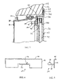
- FIG. 1 is a cross-sectional, side elevational view of a window assembly for a passenger vehicle according to a preferred embodiment of the present invention
- FIG. 2 is an enlarged, fragmented view showing a portion of the window assembly of FIG. 1 at a retention bracket;
- FIG. 3 is an enlarged, fragmented inside elevational view of the window assembly of FIGS. 1 and 2 showing the retention bracket;
- FIG. 4 is an inside elevational view of the retention bracket of the window assembly of FIGS. 1 to 3 ;
- FIG. 5 is a side elevational view of the retention bracket of FIG. 4 ;
- FIG. 6 is an enlarged, fragmented inside elevational view similar to FIG. 3 but showing an alternative retention bracket
- FIG. 7 is an enlarged, fragmented inside elevational view similar to FIGS. 3 and 6 but showing another alternative retention bracket.
- foreword or fore generally refers to a direction toward the front of the passenger vehicle and aft
- rear or rearward generally refers to a direction toward the rear of the passenger vehicle.
- inward or inner generally refers to a direction toward the inside of the passenger vehicle and outward or outer generally refers to a direction toward the outside of the passenger vehicle.
- the window assembly 10 for a passenger vehicle 12 is typically installed in a window opening 14 of a support structure such as the body of the passenger vehicle 12 .
- the passenger vehicle 12 can be, for example, a bus, a recreational vehicle, a van, a sport utility vehicle, a cross over vehicle, a rail car, and the like.
- the window opening 14 is typically defined by a header 16 , a footer 18 spaced below the header, and a pair of side jambs (not specifically shown) connecting ends of the header and footer 16 , 18 .
- FIGS. 1 to 3 illustrate a window assembly 10 for a passenger vehicle 12 according to the present invention.
- the illustrated window assembly 10 includes a frame 20 extending about a periphery of the window opening 14 , a glazing or glazing assembly at least partially closing the frame 20 and the window opening 14 , and at least one retention or retaining bracket 24 secured to the gazing assembly and forming a interlock with the frame 20 to secure the glazing assembly 22 to the frame 20 so that the glazing assembly 22 is selectively removable from the frame 20 without removing the frame 20 from the passenger vehicle 12 .
- the illustrated glazing assembly 22 includes a first or outer glazing pane 26 and a second or inner glazing pane 28 spaced inward of the outer glazing pane 26 .
- a spacer 30 is positioned between the first glazing pane 26 and the second glazing pane 28 about a periphery of the glazing panes 26 , 28 to create an insulating space or gap 32 between the glazing panes 26 , 28 .
- the insulating gap 32 provides an insulative capability for the glazing assembly 22 .
- the spacer 30 may be formed of aluminum, plastic, or any other suitable material that will become readily apparent to those skilled in the art given the benefit of this disclosure.
- the first glazing pane 26 has a thickness of at least approximately 1 ⁇ 8 inches thick
- the second glazing pane 28 has a thickness of at least approximately 1 ⁇ 8 inches thick
- the insulating gap 30 has a thickness of at least approximately 3/16 inches thick. It is noted that while the illustrated glazing assembly 22 is an insulated glazing assembly having two panes 26 , 28 , the glazing assembly 22 can alternatively have a single pane or more than two panes within the scope of the present invention.
- the illustrated frame 20 in cross-section, includes a horizontal portion 34 , an outer flange 36 perpendicularly and outwardly extending from an outer edge of the horizontal portion 34 , an inner flange 38 perpendicularly and inwardly extending from an inner edge of the horizontal portion 34 , and a seat flange 40 perpendicularly and inwardly extending from an intermediate location of the horizontal portion 34 to form an outwardly facing seat for the glazing assembly 22 .
- the outer flange 36 is sized and shaped to engage an outer surface of the header 16 .
- a seal or sealant 42 is positioned between the outer flange 36 and the header 16 to provide a weatherproof seal.
- the seal 42 is preferably formed of an elastomeric material such as natural or synthetic rubber, ethylene-propylene terploymer (EPDM), vinyl, polyvinyl chloride, thermoplastic elastomer, a closed-cell foam material or the like.
- EPDM ethylene-propylene terploymer
- vinyl vinyl
- polyvinyl chloride polyvinyl chloride
- thermoplastic elastomer a closed-cell foam material or the like.
- the illustrated seat flange 40 is sized and shaped to provide a seat for the glazing assembly 22 wherein an outer surface of the outer glazing 26 is substantially flush with the outer surface of the outer flange 36 .
- the frame 20 can alternatively be sized and shaped so that the glazing assembly 22 is not flush mounted.
- the frame 20 can alternatively be sized and shaped so that it is a hidden frame, that is, the frame 20 is substantially not visible from the outside of the passenger vehicle 12 except through the glazing assembly 22 .
- the illustrated glazing assembly 22 is seated within the frame 20 against the seat flange 40 .
- a seal or sealant 44 is positioned between the seat flange 40 and the inner glazing pane 28 to provide a weatherproof seal.
- the seal 44 is preferably formed of an elastomeric material such as natural or synthetic rubber, ethylene-propylene terploymer (EPDM), vinyl, polyvinyl chloride, thermoplastic elastomer, a closed-cell foam material or the like.
- EPDM ethylene-propylene terploymer
- vinyl vinyl
- polyvinyl chloride polyvinyl chloride
- thermoplastic elastomer a closed-cell foam material or the like.
- Other suitable materials for the seal 44 will become readily apparent to those skilled in the art given the benefit of this disclosure.
- At least one opening 46 is provided within the seat flange 40 for passage of the retaining bracket 24 therethrough as described in more detail herein below.
- the illustrated opening 46 is provided below the seal 44 , that is, within the sealed interior.
- the illustrated opening 46 is a closed aperture in the form of a rectangular slot having substantially parallel upper and lower edges. It is noted, however, that the opening 46 can alternatively have any other suitable shape such as for example can be a notch in the lower edge of the seat flange 40 .
- the illustrated frame 20 is generally rectangular-shaped to closely match the window opening 14 but can be of any other suitable shape depending on the shape of the window opening 14 .
- the frame 20 may be a continuous one piece component or can be several components secured together.
- the frame 20 may be formed of aluminum, stainless steel, plastic, or the like. Other suitable materials for the frame 20 will become readily apparent to those skilled in the art given the benefit of this disclosure.
- the illustrated retaining bracket 24 includes a vertical portion 48 , a flange 50 perpendicularly and outwardly extending from an edge of the vertical portion 48 , a horizontal portion 52 perpendicularly and inwardly extending from an intermediate location of the vertical portion 48 , and a tab 54 extending from the horizontal portion 52 .
- the flange 50 is sized and shaped to extend along the top edge of the inner glazing pane 28 .
- the vertical portion 48 is sized and shaped to extend along the inner surface of the inner glazing pane 28 .
- the horizontal portion 52 is sized and shaped to extend through the opening 46 in the frame 20 to position the tab 54 at the inner side of the seat flange 40 of the frame 20 .
- the tab 54 is sized and shaped to form the interlock with the seat flange 40 as described in more detail hereinafter.
- the illustrated retaining bracket 24 is a unitary, one-piece component formed by bending sheet metal. It is noted, however, other suitable materials for the retaining bracket 24 will become readily apparent to those skilled in the art given the benefit of this disclosure.
- the illustrated retaining bracket 24 is secured to the glazing assembly 22 with adhesive 56 but can alternatively be secured in other manner such as mechanical fasteners or the like. Other suitable connections for the retaining bracket 24 will become readily apparent to those skilled in the art given the benefit of this disclosure.
- the retaining bracket 24 With the retaining bracket 24 secured to the glazing assembly 22 , the retaining bracket 24 extends through the frame opening 46 so that the tab 54 is positioned on the opposite side of the seat flange 40 to form an interlock with the seat flange 40 to retain the glazing assembly 22 to the frame 20 .
- the illustrated tab 54 engages the upper edge (as viewed in FIGS. 2 and 3 ) of the opening 46 to form the interlock.
- the illustrated window assembly 10 is provided with one of the retaining brackets 24 at each side of the glazing assembly 22 . It is noted, however, that a greater or lesser number of retaining brackets 24 can be utilized within the scope of the present invention. For example, there can be more than one retaining bracket 24 on a side and/or there can be retaining brackets 24 on less than all of the sides.
- the tabs 54 are bent and/or removed so that the inner portions of the retaining brackets 24 can be removed through the openings 46 to remove the glazing assembly 22 from the frame 20 without removing the frame 20 from the passenger vehicle 12 .
- the inner portions of the retaining brackets 24 are inserted through the openings 46 and the tabs 54 are bent to form the interlock with the seat flange 40 to secure the glazing assembly 22 to the frame 20 .
- FIG. 6 illustrates that the retaining bracket 24 can alternatively have other configurations.
- the alternative retaining bracket 24 shows that there can be more than one of the tabs 54 .
- the illustrated retaining bracket 24 has first and second tabs 54 , 58 extending from opposite sides of the horizontal portion 52 and in opposite directions. Configured in this manner, the tabs 54 , 58 engage opposite edges of the opening 46 to form the interlock.
- the illustrated window assembly 10 provides a serviceable glazing assembly 22 that can be repaired and/or replaced without removing the frame 20 from the passenger vehicle 12 .
Abstract
Description
Claims (18)
Priority Applications (1)
| Application Number | Priority Date | Filing Date | Title |
|---|---|---|---|
| US11/290,659 US7469509B2 (en) | 2005-11-29 | 2005-11-29 | Window assembly with serviceable glazing retention system |
Applications Claiming Priority (1)
| Application Number | Priority Date | Filing Date | Title |
|---|---|---|---|
| US11/290,659 US7469509B2 (en) | 2005-11-29 | 2005-11-29 | Window assembly with serviceable glazing retention system |
Publications (2)
| Publication Number | Publication Date |
|---|---|
| US20070130851A1 US20070130851A1 (en) | 2007-06-14 |
| US7469509B2 true US7469509B2 (en) | 2008-12-30 |
Family
ID=38137873
Family Applications (1)
| Application Number | Title | Priority Date | Filing Date |
|---|---|---|---|
| US11/290,659 Expired - Fee Related US7469509B2 (en) | 2005-11-29 | 2005-11-29 | Window assembly with serviceable glazing retention system |
Country Status (1)
| Country | Link |
|---|---|
| US (1) | US7469509B2 (en) |
Cited By (4)
| Publication number | Priority date | Publication date | Assignee | Title |
|---|---|---|---|---|
| US20090145040A1 (en) * | 2007-10-10 | 2009-06-11 | Macphail Bryan Daniel | Clip-in window assembly for vehicles |
| US20120131867A1 (en) * | 2010-11-29 | 2012-05-31 | Atwood Mobile Products Llc | Flexible clamp frame and installation method for window |
| US10385607B2 (en) * | 2014-04-28 | 2019-08-20 | Jan Franck | Fixed glazing |
| US11503796B2 (en) * | 2010-08-25 | 2022-11-22 | Hochland Se | Device for producing processed cheese portions |
Citations (17)
| Publication number | Priority date | Publication date | Assignee | Title |
|---|---|---|---|---|
| JPS57209421A (en) * | 1981-06-20 | 1982-12-22 | Hori Glass Kk | Retainer for window glass of automobiles |
| JPS5989214A (en) * | 1982-11-08 | 1984-05-23 | Tougou Seisakusho:Kk | Holding device for window molding in automobiles |
| US4561223A (en) * | 1983-02-03 | 1985-12-31 | Defender Energy Of Connecticut, Inc. | Panel fastener system and retaining member |
| JPS62191217A (en) * | 1986-02-17 | 1987-08-21 | Nissan Motor Co Ltd | Fixing device for automobile window panel |
| JPS62210120A (en) * | 1986-03-12 | 1987-09-16 | Toyoda Gosei Co Ltd | Lighting window for vehicle |
| US4703973A (en) * | 1983-09-02 | 1987-11-03 | Toyota Jidosha Kabushiki Kaisha | Mounting apparatus for a vehicle window |
| JPS63184520A (en) * | 1987-01-27 | 1988-07-30 | Hino Motors Ltd | Window molding for automobile |
| US4951907A (en) * | 1989-03-14 | 1990-08-28 | Peter Gold | Automotive window retention system and retention element therefor |
| US4986595A (en) * | 1990-01-24 | 1991-01-22 | Gold Peter N | Mechanical interlock of curable sealant for modular framed auto glass parts |
| US5531496A (en) * | 1994-07-28 | 1996-07-02 | Saturn Corporation | Automotive glass enclosure retaining fixture |
| US6101772A (en) * | 1999-02-23 | 2000-08-15 | Dinesol Plastics, Inc. | Window-mounting device |
| US6224136B1 (en) * | 1998-03-06 | 2001-05-01 | Nissan Motor Co., Ltd. | Structure for positioning windshield for vehicle and method of mounting windshield |
| US20010030449A1 (en) * | 1997-11-18 | 2001-10-18 | Saint-Gobain Vitrage | Quickly detachable glazing sheet |
| US6378931B1 (en) * | 1999-10-29 | 2002-04-30 | Exatec, Llc. | Molded plastic automotive window panel and method of installation |
| US6694683B2 (en) * | 2001-10-19 | 2004-02-24 | Illinois Tool Works Inc. | Sight glass retainer system and method for making same |
| US20040251714A1 (en) * | 2003-06-12 | 2004-12-16 | Guardian Industries Corp. | System for attaching colored insert to vehicle frame assembly |
| US20070063539A1 (en) * | 2005-09-12 | 2007-03-22 | Dimario Joseph | Snap-in mounting clip, panel having a snap-in mounting clip, and method of mounting the panel |
-
2005
- 2005-11-29 US US11/290,659 patent/US7469509B2/en not_active Expired - Fee Related
Patent Citations (18)
| Publication number | Priority date | Publication date | Assignee | Title |
|---|---|---|---|---|
| JPS57209421A (en) * | 1981-06-20 | 1982-12-22 | Hori Glass Kk | Retainer for window glass of automobiles |
| JPS5989214A (en) * | 1982-11-08 | 1984-05-23 | Tougou Seisakusho:Kk | Holding device for window molding in automobiles |
| US4561223A (en) * | 1983-02-03 | 1985-12-31 | Defender Energy Of Connecticut, Inc. | Panel fastener system and retaining member |
| US4703973A (en) * | 1983-09-02 | 1987-11-03 | Toyota Jidosha Kabushiki Kaisha | Mounting apparatus for a vehicle window |
| JPS62191217A (en) * | 1986-02-17 | 1987-08-21 | Nissan Motor Co Ltd | Fixing device for automobile window panel |
| JPS62210120A (en) * | 1986-03-12 | 1987-09-16 | Toyoda Gosei Co Ltd | Lighting window for vehicle |
| JPS63184520A (en) * | 1987-01-27 | 1988-07-30 | Hino Motors Ltd | Window molding for automobile |
| US4951907A (en) * | 1989-03-14 | 1990-08-28 | Peter Gold | Automotive window retention system and retention element therefor |
| US4986595A (en) * | 1990-01-24 | 1991-01-22 | Gold Peter N | Mechanical interlock of curable sealant for modular framed auto glass parts |
| US5531496A (en) * | 1994-07-28 | 1996-07-02 | Saturn Corporation | Automotive glass enclosure retaining fixture |
| US20010030449A1 (en) * | 1997-11-18 | 2001-10-18 | Saint-Gobain Vitrage | Quickly detachable glazing sheet |
| US6364404B1 (en) * | 1997-11-18 | 2002-04-02 | Saint-Gobain Vitrage | Quickly detachable glazing sheet |
| US6224136B1 (en) * | 1998-03-06 | 2001-05-01 | Nissan Motor Co., Ltd. | Structure for positioning windshield for vehicle and method of mounting windshield |
| US6101772A (en) * | 1999-02-23 | 2000-08-15 | Dinesol Plastics, Inc. | Window-mounting device |
| US6378931B1 (en) * | 1999-10-29 | 2002-04-30 | Exatec, Llc. | Molded plastic automotive window panel and method of installation |
| US6694683B2 (en) * | 2001-10-19 | 2004-02-24 | Illinois Tool Works Inc. | Sight glass retainer system and method for making same |
| US20040251714A1 (en) * | 2003-06-12 | 2004-12-16 | Guardian Industries Corp. | System for attaching colored insert to vehicle frame assembly |
| US20070063539A1 (en) * | 2005-09-12 | 2007-03-22 | Dimario Joseph | Snap-in mounting clip, panel having a snap-in mounting clip, and method of mounting the panel |
Cited By (6)
| Publication number | Priority date | Publication date | Assignee | Title |
|---|---|---|---|---|
| US20090145040A1 (en) * | 2007-10-10 | 2009-06-11 | Macphail Bryan Daniel | Clip-in window assembly for vehicles |
| US7753434B2 (en) * | 2007-10-10 | 2010-07-13 | Dura Global Technologies, Llc | Clip-in window assembly for vehicles |
| US11503796B2 (en) * | 2010-08-25 | 2022-11-22 | Hochland Se | Device for producing processed cheese portions |
| US20120131867A1 (en) * | 2010-11-29 | 2012-05-31 | Atwood Mobile Products Llc | Flexible clamp frame and installation method for window |
| US8327603B2 (en) * | 2010-11-29 | 2012-12-11 | Atwood Mobile Products Llc | Flexible clamp frame and installation method for window |
| US10385607B2 (en) * | 2014-04-28 | 2019-08-20 | Jan Franck | Fixed glazing |
Also Published As
| Publication number | Publication date |
|---|---|
| US20070130851A1 (en) | 2007-06-14 |
Similar Documents
| Publication | Publication Date | Title |
|---|---|---|
| US10150512B2 (en) | Automobile pillar structure | |
| JP4661341B2 (en) | Automotive roof structure | |
| US5893600A (en) | Reglazable window | |
| US20020078631A1 (en) | Lightweight door for motor vehicles | |
| US20080122262A1 (en) | Multi-Pane Window Assembly With Two-Sided Frame | |
| US20110272974A1 (en) | Whole glass roof for a motor vehicle | |
| US7469509B2 (en) | Window assembly with serviceable glazing retention system | |
| US20040111973A1 (en) | Weatherstrip forming a slideway for a motor vehicle window | |
| US10118651B2 (en) | Interior body panel fit and finish tabs and methods of installation and use thereof | |
| US8033597B2 (en) | Glazed transit vehicle door or window | |
| GB2047784A (en) | Glazing vehicle windows | |
| US3600858A (en) | Weatherstrip assembly | |
| GB2111573A (en) | Glazing strip | |
| US2261038A (en) | Window panel mounting | |
| US7188399B2 (en) | Method of fitting flush glazing | |
| US20050072053A1 (en) | Seal and molding assembly | |
| US20040060242A1 (en) | Weatherstrip forming a slideway for a motor vehicle window | |
| US3744186A (en) | Vehicle window structure | |
| US8297683B2 (en) | Mounting frame member for motor vehicle tailgate having frameless window pane | |
| US9789752B1 (en) | Window shade hook assembly, and methods of use and manufacture thereof | |
| JP2008179234A (en) | Mounting structure for weather strip | |
| CN212685543U (en) | Rail vehicle | |
| JP6094445B2 (en) | Vehicle door mounting structure | |
| CN218400171U (en) | Roof sealing structure of convertible car and convertible car | |
| CN215761228U (en) | Novel window for cross-country caravan |
Legal Events
| Date | Code | Title | Description |
|---|---|---|---|
| AS | Assignment |
Owner name: DURA GLOBAL TECHNOLOGIES, INC., MICHIGAN Free format text: ASSIGNMENT OF ASSIGNORS INTEREST;ASSIGNOR:CRIPE, TODD ELLSWORTH;REEL/FRAME:017309/0001 Effective date: 20051129 |
|
| AS | Assignment |
Owner name: GOLDMAN SACHS CREDIT PARTNERS, LP,NEW YORK Free format text: SECURITY AGREEMENT;ASSIGNORS:DURA AUTOMOTIVE SYSTEMS, INC.;ATWOOD MOBILE PRODUCTS, INC.;UNIVERSAL TOOL & STAMPING COMPANY, INC.;AND OTHERS;REEL/FRAME:018654/0176 Effective date: 20061031 Owner name: GOLDMAN SACHS CREDIT PARTNERS, LP, NEW YORK Free format text: SECURITY AGREEMENT;ASSIGNORS:DURA AUTOMOTIVE SYSTEMS, INC.;ATWOOD MOBILE PRODUCTS, INC.;UNIVERSAL TOOL & STAMPING COMPANY, INC.;AND OTHERS;REEL/FRAME:018654/0176 Effective date: 20061031 Owner name: GOLDMAN SACHS CREDIT PARTNERS, LP, NEW YORK Free format text: ASSIGNMENT OF ASSIGNORS INTEREST;ASSIGNORS:DURA AUTOMOTIVE SYSTEMS, INC.;ATWOOD MOBILE PRODUCTS, INC.;UNIVERSAL TOOL & STAMPING COMPANY, INC.;AND OTHERS;REEL/FRAME:018654/0176 Effective date: 20061031 |
|
| AS | Assignment |
Owner name: DURA OPERATING CORP., MICHIGAN Free format text: TERMINATION AND RELEASE;ASSIGNOR:GOLDMAN SACHS CREDIT PARTNERS, L.P., AS COLLATERAL AGRENT;REEL/FRAME:020478/0674 Effective date: 20080130 Owner name: UNIVERSAL TOOL & STAMPING COMPANY, INC., MICHIGAN Free format text: TERMINATION AND RELEASE;ASSIGNOR:GOLDMAN SACHS CREDIT PARTNERS, L.P., AS COLLATERAL AGRENT;REEL/FRAME:020478/0674 Effective date: 20080130 Owner name: DURA AUTOMOTIVE SYSTEMS CABLE OPERATIONS, INC., MI Free format text: TERMINATION AND RELEASE;ASSIGNOR:GOLDMAN SACHS CREDIT PARTNERS, L.P., AS COLLATERAL AGRENT;REEL/FRAME:020478/0674 Effective date: 20080130 Owner name: DURA GLOBAL TECHNOLOGIES, INC., MICHIGAN Free format text: TERMINATION AND RELEASE;ASSIGNOR:GOLDMAN SACHS CREDIT PARTNERS, L.P., AS COLLATERAL AGRENT;REEL/FRAME:020478/0674 Effective date: 20080130 Owner name: ATWOOD MOBILE PRODUCTS, INC., MICHIGAN Free format text: TERMINATION AND RELEASE;ASSIGNOR:GOLDMAN SACHS CREDIT PARTNERS, L.P., AS COLLATERAL AGRENT;REEL/FRAME:020478/0674 Effective date: 20080130 Owner name: DURA AUTOMOTIVE SYSTEMS, INC., MICHIGAN Free format text: TERMINATION AND RELEASE;ASSIGNOR:GOLDMAN SACHS CREDIT PARTNERS, L.P., AS COLLATERAL AGRENT;REEL/FRAME:020478/0674 Effective date: 20080130 Owner name: DURA OPERATING CORP.,MICHIGAN Free format text: TERMINATION AND RELEASE;ASSIGNOR:GOLDMAN SACHS CREDIT PARTNERS, L.P., AS COLLATERAL AGRENT;REEL/FRAME:020478/0674 Effective date: 20080130 Owner name: UNIVERSAL TOOL & STAMPING COMPANY, INC.,MICHIGAN Free format text: TERMINATION AND RELEASE;ASSIGNOR:GOLDMAN SACHS CREDIT PARTNERS, L.P., AS COLLATERAL AGRENT;REEL/FRAME:020478/0674 Effective date: 20080130 Owner name: DURA AUTOMOTIVE SYSTEMS CABLE OPERATIONS, INC.,MIC Free format text: TERMINATION AND RELEASE;ASSIGNOR:GOLDMAN SACHS CREDIT PARTNERS, L.P., AS COLLATERAL AGRENT;REEL/FRAME:020478/0674 Effective date: 20080130 Owner name: DURA GLOBAL TECHNOLOGIES, INC.,MICHIGAN Free format text: TERMINATION AND RELEASE;ASSIGNOR:GOLDMAN SACHS CREDIT PARTNERS, L.P., AS COLLATERAL AGRENT;REEL/FRAME:020478/0674 Effective date: 20080130 Owner name: ATWOOD MOBILE PRODUCTS, INC.,MICHIGAN Free format text: TERMINATION AND RELEASE;ASSIGNOR:GOLDMAN SACHS CREDIT PARTNERS, L.P., AS COLLATERAL AGRENT;REEL/FRAME:020478/0674 Effective date: 20080130 Owner name: DURA AUTOMOTIVE SYSTEMS, INC.,MICHIGAN Free format text: TERMINATION AND RELEASE;ASSIGNOR:GOLDMAN SACHS CREDIT PARTNERS, L.P., AS COLLATERAL AGRENT;REEL/FRAME:020478/0674 Effective date: 20080130 |
|
| AS | Assignment |
Owner name: WILMINGTON TRUST COMPANY, AS SECOND LIEN COLLATERA Free format text: SECOND LIEN PATENT SECURITY AGREEMENT;ASSIGNOR:DURA GLOBAL TECHNOLOGIES, INC.;REEL/FRAME:021590/0917 Effective date: 20080627 |
|
| STCF | Information on status: patent grant |
Free format text: PATENTED CASE |
|
| AS | Assignment |
Owner name: GENERAL ELECTRIC CAPITAL CORPORATION, AS AGENT, IL Free format text: SECURITY AGREEMENT;ASSIGNORS:DURA GLOBAL TECHNOLOGIES, INC.;ATWOOD MOBILE PRODUCTS, INC. (AN ILLINOIS CORPORATION);DURA OPERATING CORP. (A DELAWARE CORPORATION);AND OTHERS;REEL/FRAME:022482/0336 Effective date: 20080627 Owner name: GENERAL ELECTRIC CAPITAL CORPORATION, AS AGENT,ILL Free format text: SECURITY AGREEMENT;ASSIGNORS:DURA GLOBAL TECHNOLOGIES, INC.;ATWOOD MOBILE PRODUCTS, INC. (AN ILLINOIS CORPORATION);DURA OPERATING CORP. (A DELAWARE CORPORATION);AND OTHERS;REEL/FRAME:022482/0336 Effective date: 20080627 |
|
| AS | Assignment |
Owner name: DURA GLOBAL TECHNOLOGIES, INC.,MICHIGAN Free format text: RELEASE OF SECURITY INTEREST IN PATENTS AS RECORDE;ASSIGNOR:GENERAL ELECTRIC CAPITAL CORPORATION, AS COLLATERAL AGENT;REEL/FRAME:023963/0961 Effective date: 20100107 Owner name: ATWOOD MOBILE PRODUCTS, INC.,MICHIGAN Free format text: RELEASE OF SECURITY INTEREST IN PATENTS AS RECORDE;ASSIGNOR:GENERAL ELECTRIC CAPITAL CORPORATION, AS COLLATERAL AGENT;REEL/FRAME:023963/0961 Effective date: 20100107 Owner name: DURA AUTOMOTIVE SYSTEMS CABLE OPERATIONS, INC.,MIC Free format text: RELEASE OF SECURITY INTEREST IN PATENTS AS RECORDE;ASSIGNOR:GENERAL ELECTRIC CAPITAL CORPORATION, AS COLLATERAL AGENT;REEL/FRAME:023963/0961 Effective date: 20100107 Owner name: DURA OPERATING CORP.,MICHIGAN Free format text: RELEASE OF SECURITY INTEREST IN PATENTS AS RECORDE;ASSIGNOR:GENERAL ELECTRIC CAPITAL CORPORATION, AS COLLATERAL AGENT;REEL/FRAME:023963/0961 Effective date: 20100107 Owner name: WACHOVIA CAPITAL FINANCE CORPORATION (CENTRAL),ILL Free format text: SECURITY AGREEMENT;ASSIGNOR:DURA GLOBAL TECHNOLOGIES, INC.;REEL/FRAME:023957/0946 Effective date: 20100121 Owner name: WACHOVIA CAPITAL FINANCE CORPORATION (CENTRAL), IL Free format text: SECURITY AGREEMENT;ASSIGNOR:DURA GLOBAL TECHNOLOGIES, INC.;REEL/FRAME:023957/0946 Effective date: 20100121 Owner name: DURA GLOBAL TECHNOLOGIES, INC., MICHIGAN Free format text: RELEASE OF SECURITY INTEREST IN PATENTS AS RECORDE;ASSIGNOR:GENERAL ELECTRIC CAPITAL CORPORATION, AS COLLATERAL AGENT;REEL/FRAME:023963/0961 Effective date: 20100107 Owner name: ATWOOD MOBILE PRODUCTS, INC., MICHIGAN Free format text: RELEASE OF SECURITY INTEREST IN PATENTS AS RECORDE;ASSIGNOR:GENERAL ELECTRIC CAPITAL CORPORATION, AS COLLATERAL AGENT;REEL/FRAME:023963/0961 Effective date: 20100107 Owner name: DURA AUTOMOTIVE SYSTEMS CABLE OPERATIONS, INC., MI Free format text: RELEASE OF SECURITY INTEREST IN PATENTS AS RECORDE;ASSIGNOR:GENERAL ELECTRIC CAPITAL CORPORATION, AS COLLATERAL AGENT;REEL/FRAME:023963/0961 Effective date: 20100107 Owner name: DURA OPERATING CORP., MICHIGAN Free format text: RELEASE OF SECURITY INTEREST IN PATENTS AS RECORDE;ASSIGNOR:GENERAL ELECTRIC CAPITAL CORPORATION, AS COLLATERAL AGENT;REEL/FRAME:023963/0961 Effective date: 20100107 |
|
| AS | Assignment |
Owner name: DURA GLOBAL TECHNOLOGIES, INC.,MICHIGAN Free format text: RELEASE BY SECURED PARTY;ASSIGNOR:WILMINGTON TRUST COMPANY;REEL/FRAME:023915/0548 Effective date: 20100121 Owner name: ATWOOD MOBILE PRODUCTS, INC.,MICHIGAN Free format text: RELEASE BY SECURED PARTY;ASSIGNOR:WILMINGTON TRUST COMPANY;REEL/FRAME:023915/0548 Effective date: 20100121 Owner name: DURA AUTOMOTIVE SYSTEMS CABLE OPERATIONS, INC.,MIC Free format text: RELEASE BY SECURED PARTY;ASSIGNOR:WILMINGTON TRUST COMPANY;REEL/FRAME:023915/0548 Effective date: 20100121 Owner name: DURA OPERATING CORP.,MICHIGAN Free format text: RELEASE BY SECURED PARTY;ASSIGNOR:WILMINGTON TRUST COMPANY;REEL/FRAME:023915/0548 Effective date: 20100121 Owner name: DURA GLOBAL TECHNOLOGIES, INC., MICHIGAN Free format text: RELEASE BY SECURED PARTY;ASSIGNOR:WILMINGTON TRUST COMPANY;REEL/FRAME:023915/0548 Effective date: 20100121 Owner name: ATWOOD MOBILE PRODUCTS, INC., MICHIGAN Free format text: RELEASE BY SECURED PARTY;ASSIGNOR:WILMINGTON TRUST COMPANY;REEL/FRAME:023915/0548 Effective date: 20100121 Owner name: DURA AUTOMOTIVE SYSTEMS CABLE OPERATIONS, INC., MI Free format text: RELEASE BY SECURED PARTY;ASSIGNOR:WILMINGTON TRUST COMPANY;REEL/FRAME:023915/0548 Effective date: 20100121 Owner name: DURA OPERATING CORP., MICHIGAN Free format text: RELEASE BY SECURED PARTY;ASSIGNOR:WILMINGTON TRUST COMPANY;REEL/FRAME:023915/0548 Effective date: 20100121 |
|
| AS | Assignment |
Owner name: PATRIARCH PARTNERS AGENCY SERVICES, LLC,NEW YORK Free format text: SECURITY AGREEMENT;ASSIGNORS:DURA OPERATING CORP.;ATWOOD MOBILE PRODUCTS, INC.;DURA AUTOMOTIVE SYSTEMS, INC.;AND OTHERS;REEL/FRAME:024055/0001 Effective date: 20100121 Owner name: PATRIARCH PARTNERS AGENCY SERVICES, LLC, NEW YORK Free format text: SECURITY AGREEMENT;ASSIGNORS:DURA OPERATING CORP.;ATWOOD MOBILE PRODUCTS, INC.;DURA AUTOMOTIVE SYSTEMS, INC.;AND OTHERS;REEL/FRAME:024055/0001 Effective date: 20100121 |
|
| AS | Assignment |
Owner name: DEUTSCHE BANK TRUST COMPANY AMERICAS,NEW YORK Free format text: SECURITY AGREEMENT;ASSIGNORS:DURA OPERATING CORP.;ATWOOD MOBILE PRODUCTS, INC.;DURA AUTOMOTIVE SYSTEMS, INC.;AND OTHERS;REEL/FRAME:024195/0001 Effective date: 20100121 Owner name: DEUTSCHE BANK TRUST COMPANY AMERICAS, NEW YORK Free format text: SECURITY AGREEMENT;ASSIGNORS:DURA OPERATING CORP.;ATWOOD MOBILE PRODUCTS, INC.;DURA AUTOMOTIVE SYSTEMS, INC.;AND OTHERS;REEL/FRAME:024195/0001 Effective date: 20100121 |
|
| AS | Assignment |
Owner name: WILMINGTON TRUST (LONDON) LIMITED,UNITED KINGDOM Free format text: SECURITY AGREEMENT;ASSIGNORS:DURA OPERATING CORP.;ATWOOD MOBILE PRODUCTS, INC.;DURA AUTOMOTIVE SYSTEMS, INC.;AND OTHERS;REEL/FRAME:024244/0282 Effective date: 20100121 Owner name: WILMINGTON TRUST (LONDON) LIMITED, UNITED KINGDOM Free format text: SECURITY AGREEMENT;ASSIGNORS:DURA OPERATING CORP.;ATWOOD MOBILE PRODUCTS, INC.;DURA AUTOMOTIVE SYSTEMS, INC.;AND OTHERS;REEL/FRAME:024244/0282 Effective date: 20100121 |
|
| FPAY | Fee payment |
Year of fee payment: 4 |
|
| FPAY | Fee payment |
Year of fee payment: 8 |
|
| FEPP | Fee payment procedure |
Free format text: MAINTENANCE FEE REMINDER MAILED (ORIGINAL EVENT CODE: REM.); ENTITY STATUS OF PATENT OWNER: LARGE ENTITY |
|
| LAPS | Lapse for failure to pay maintenance fees |
Free format text: PATENT EXPIRED FOR FAILURE TO PAY MAINTENANCE FEES (ORIGINAL EVENT CODE: EXP.); ENTITY STATUS OF PATENT OWNER: LARGE ENTITY |
|
| STCH | Information on status: patent discontinuation |
Free format text: PATENT EXPIRED DUE TO NONPAYMENT OF MAINTENANCE FEES UNDER 37 CFR 1.362 |
|
| FP | Lapsed due to failure to pay maintenance fee |
Effective date: 20201230 |