US7460831B2 - System and method for excluding narrow band noise from a communication channel - Google Patents
System and method for excluding narrow band noise from a communication channel Download PDFInfo
- Publication number
- US7460831B2 US7460831B2 US11/220,870 US22087005A US7460831B2 US 7460831 B2 US7460831 B2 US 7460831B2 US 22087005 A US22087005 A US 22087005A US 7460831 B2 US7460831 B2 US 7460831B2
- Authority
- US
- United States
- Prior art keywords
- signal
- digital
- filtering
- frequency
- filter
- Prior art date
- Legal status (The legal status is an assumption and is not a legal conclusion. Google has not performed a legal analysis and makes no representation as to the accuracy of the status listed.)
- Expired - Lifetime, expires
Links
Images


Classifications
-
- H—ELECTRICITY
- H04—ELECTRIC COMMUNICATION TECHNIQUE
- H04B—TRANSMISSION
- H04B1/00—Details of transmission systems, not covered by a single one of groups H04B3/00 - H04B13/00; Details of transmission systems not characterised by the medium used for transmission
- H04B1/69—Spread spectrum techniques
- H04B1/707—Spread spectrum techniques using direct sequence modulation
- H04B1/7097—Interference-related aspects
- H04B1/71—Interference-related aspects the interference being narrowband interference
-
- H—ELECTRICITY
- H04—ELECTRIC COMMUNICATION TECHNIQUE
- H04B—TRANSMISSION
- H04B7/00—Radio transmission systems, i.e. using radiation field
- H04B7/14—Relay systems
-
- H—ELECTRICITY
- H04—ELECTRIC COMMUNICATION TECHNIQUE
- H04B—TRANSMISSION
- H04B7/00—Radio transmission systems, i.e. using radiation field
- H04B7/14—Relay systems
- H04B7/15—Active relay systems
- H04B7/155—Ground-based stations
- H04B7/15528—Control of operation parameters of a relay station to exploit the physical medium
- H04B7/15542—Selecting at relay station its transmit and receive resources
-
- H—ELECTRICITY
- H04—ELECTRIC COMMUNICATION TECHNIQUE
- H04B—TRANSMISSION
- H04B7/00—Radio transmission systems, i.e. using radiation field
- H04B7/14—Relay systems
- H04B7/15—Active relay systems
- H04B7/155—Ground-based stations
- H04B7/15564—Relay station antennae loop interference reduction
- H04B7/15578—Relay station antennae loop interference reduction by gain adjustment
Definitions
- the present invention relates generally to the field of communications. More specifically, the present invention relates to digital filtering of one or more communication channels.
- Degradation of signal-to-noise ratio (“SNR”) as well as Bit energy to noise ratio (“Eb/No”) or Bit energy to interference ratio (“Eb/I”) or Carrier to-Interference (“C/I”) ratio may occur due to interference signals that may typically appear in a communication channel with a desired received signal carried along a transmission medium (e.g. coax, unshielded conductor, wave guide, open air or even optical fiber or RF over fiber) at the receiver input.
- a transmission medium e.g. coax, unshielded conductor, wave guide, open air or even optical fiber or RF over fiber
- These degradations and interferences may occur in communications technologies including, for: example, CDMA, EVDO, and WCDMA, respectively operating under the 3G CDMA 2000 and UMTS standards, as well as TDMA and GSM.
- Signal quality attenuation and its resulting Eb/I degradation may limit bandwidth over a transmission medium. Interference from outside signals within the frequency range of a communication channel may also reduce Eb/I of the channel and reduce the amount of data the channel may carry and/or may block or saturate the communication channel receiver. In some situations, it may cause a loss of a full frequency channel. Additionally, in some situations, Eb/I degradation, e.g., due to interference signals, may render a communication (traffic or control) channel inoperative and may even degrade the base station capacity.
- signal repeaters may be placed at intervals along the transmitting path.
- Repeaters are well known and may be used for optical, microwave and radio frequency (RF) communication systems. Repeaters have been used as part of cellular transmission systems to extend the range of coverage between a cellular base station and a cellular handset.
- RF radio frequency
- a broadband repeater e.g., pass wide range of operating frequencies
- a frequency range of the spectrum e.g. 800 MHz, 900 MHz, PCS, Public Safety, or any other network operating band
- interference signals present in the vicinity of the repeater, and within the frequency range of one of the communication channels to be repeated may also be repeated and amplified by the repeater, effectively reducing the Eb/I of a communication channel to be repeated.
- Interference signals may further introduce interferences to a base station receiver that may cause, for example, a CDMA cell shrink, or may lower the base station capacity.
- FIG. 1A there is shown a spectral diagram exemplifying frequency bands or channels (e.g. 1.25 MHz each) of a first cellular operator which may be used within the frequency range of the “Operating Band” in a CDMA channel.
- a narrow band interference signal of, for example, 25 KHz bandwidth, introduced by some outside source, within the frequency range of a second communication channel of the first cellular operator.
- the interference signals may reduce the Eb/I of one or more communication channels, and the use of a conventional repeater may serve to boost the interference signal and reduce the Eb/I of the communication channel with which it is interfering.
- Repeaters, as part of a Cellular network system are typically installed geographically far from base station coverage. The interference may appear in the vicinity of the repeater receiver horizon or in the vicinity of the base station receiver horizon, and may create a problem from the horizon to the base station receiver. Repeaters and/or base stations are not generally capable of solving these problems.
- FIG. 1B shows a spectral diagram exemplifying possible channel frequency bands that a second cellular operator may use in the same geographic location as the first cellular operator of FIG. 1A .
- the second operator of FIG. 1B may use communication channels with a narrower bandwidth (e.g. 200 KHz) than those used by the first operator in FIG. 1A , and may also use two or more communication channels having adjacent frequency bands, to create the required traffic capability.
- one channel may be primarily used for traffic and the other channels may be primarily used for access. All channels may generally need to be operational, so that the communication may be adequately performed. This scenario may typically occur in broader areas, e.g., between states, countries, or in areas close to water such as lakes and seas.
- Base stations that are installed near a water source may receive an undesired signal from far base stations or even from far countries because water is an excellent conducer of RF waves. Accordingly, as shown in FIG. 1A , the frequency bands of the operator B, e.g., the third channel in FIG. 1B , may overlap and interfere with the frequency bands of operator A, e.g., with the second channel in FIG. 1A . Additionally or alternatively, as shown in FIG. 1B , the frequency bands of the operator A, e.g., the fourth channel in FIG. 1A , may overlap and interfere with the frequency bands of operator B, e.g., with the sixth channel in FIG. 1B .
- Another exemplary scenario of communication without using a repeater may occur in the context of an outdoor environment.
- interferences in the operating base station receiver e.g., interference signals such as TV stations or other cellular operators. These interferences may affect the base station, for example resulting in cell shrinkage and/or lower base station capacity.
- the interference signal may have an adverse effect on the base station receiver. Either the receiver may not be able to extract data from the channel, or in some cases, the receiver may fully block the receiver capacity or control channel.
- An interference signal may be of a fixed nature, having relatively fixed frequencies and amplitudes.
- an interference signal may be intermittent and of an unstable nature.
- the center frequencies and frequency-band-size of communication channels used by one or more wireless service operators/providers in a given geographic location may vary substantially, and thus each channel may have considerably different filtering requirements when passing through a repeater and/or at the input stage of a base-station.
- a system and method are provided for enabling digital filtering of communication channels, including adjusting the channels center frequencies.
- the system and method may enable, for example, isolating frequencies associated with individual communication channels and/or groups of communication channels, and in some cases to extracting or excluding frequencies associated with narrow band noise, or interference from a communication channel.
- the system and method may enable, for example, adjusting the channels center frequencies.
- Some embodiments of the present invention relate to digital filtering of one or more communication channels to facilitate the operation of a repeater, by filtering communication signals received at the base-station, and/or by excluding narrow band noise/interference either at a base-station or at a repeater.
- Some embodiments of the present invention relate to a receiver that may receive a signal associated with a certain communication channel at a specific frequency.
- An analog to digital converter may generate a digital signal correlated to the received signal and the digital signal may be passed though a digital filter, configured to filter the digital signal and pass frequency components at or around the frequency of the communication channel's specific frequency.
- a digital to analog converter may generate an analog signal correlated to the filtered digital signal.
- the analog signal may be passed or inputted directly or indirectly into a base station receiver.
- a transmitter may retransmit the analog signal either to a base station, a handset or to a repeater.
- a second digital filter configured to pass frequency components, at, or around a second frequency associated with a second communication channel.
- a down-converter to down-convert a received signal to an intermediate frequency signal.
- the down converter may down convert the received signal to a desired radio frequency signal.
- an up-converter may be included to up-convert to a transmission frequency an analog signal correlated to the filtered digital signal.
- a digital filter may be configured to filter out an interference signal.
- the digital filter may either be a notch filter or a combination of two filters having partially overlapping band pass characteristics.
- a control unit may program the first and/or second digital filters according to digital filter parameters and/or coefficients, stored in a filter parameter database.
- the controller may also receive digital filter parameters and/or coefficients from a remote location through a modem.
- the control unit may receive signals from one or more performance monitors of a system according to present invention indicating performance parameters, such as signal delay, phase shift, gain, and presence of noise/interference.
- the controller may adjust or change the digital filter parameters and/or coefficients of one or more digital filter in order to bring system performance within operational requirements.
- the digital signal may be mixed with a digital sinusoidal signal at a shifted frequency Fshift.
- the shifted frequency may be set and adjusted by the controller, either in response to performance monitor signals or based on instructions received through a modem.
- an analog signal produced by the digital to analog converter may be provided to the input of a base station receiver.
- one or more of the filter elements may include a time domain to frequency domain conversion engine, a frame shaping unit, and a frequency domain to time domain conversion engine.
- the frequency domain conversion engine and the method to operate the engine may provide capabilities to monitoring the communication channel traffic and may enable to detect interferences characteristics.
- the data on the existing interference and its characteristic may give a tool, for example, to a customer, to decide if the communication channel is damageable from the interference.
- FIG. 1A is a spectral diagram showing four multi-frequency signals of four, respective, communication channels, which may be used by a cellular operator in a specific geographic region, where the second communication channel is corrupted by an interference signal;
- FIG. 1B is a spectral diagram showing five multi-frequency signals of five, respective, communication channels, which may be used by a second wireless service provider/operator in a specific geographic region, where the communication channels are of a smaller bandwidth than those of FIG. 1A and wherein two pairs of channels are adjacent to one another;
- FIG. 2A is a block diagram showing an example of a bi-directional repeater with digital filters and digital frequency shifters according to some embodiments of the present invention
- FIG. 2B is a block diagram showing an example of a bi-directional repeater with digital filters, a control unit, a performance monitor, and a modem according to some embodiments of the present invention
- FIG. 3 is a block diagram showing one possible embodiment of the digital filters and frequency shifters block of FIG. 2A ;
- FIGS. 4A to 4C are spectral diagrams showing examples of frequency responses of digital filters 1400 A through 1400 D in FIG. 3 ;
- FIG. 4D is a spectral diagram showing an example of a frequency domain representation of a digital sinusoidal signal at a shifted frequency
- FIGS. 4E and 4F are spectral diagrams showing examples of frequency shifted communication channels
- FIG. 5A shows a block diagram of a multiple-channel digital filtering configuration or block according to some embodiments of the present invention
- FIG. 5B is a series of spectral diagrams illustrating exemplary effects on a signal by elements in the uplink path of the multiple-channel digital filtering block of FIG. 5A ;
- FIG. 5C is a series of spectral diagrams illustrating exemplary effects on a signal by elements in the downlink path of the multiple-path digital filtering configuration of FIG. 5A ;
- FIG. 6A is a block diagram of an alternative digital filtering configuration or block 140 incorporating a Fast Fourier Transform (“FFT”), programmable frame shaping, and an Inverse Fast Fourier Transform (“IFFT”), according to some embodiments of the present invention
- FIG. 6B is a series of time domain and spectral diagrams illustrating exemplary effects on a signal by each element in the digital filtering block of FIG. 6A .
- FIG. 7 is a block diagram showing another example of a bi-directional repeater with digital filters and digital frequency shifters according to some embodiments of the present invention, where digital filter and frequency shifting parameters may be adjusted and/or regulated;
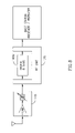
- FIG. 8 is a block diagram showing a communication channel with digital filtering system and or frequency shifting, which may be combined, for example, with a Tower Mounted Amplifier (TMA) or Tower Top Amplifier (TTA) in front of a base station front end according to some embodiments of the present invention configured to operate in conjunction with a base station; and
- TMA Tower Mounted Amplifier
- TTA Tower Top Amplifier
- FIG. 9 is a flow chart describing a method of implementing digital filtering, according to some embodiments of the present invention.
- Embodiments of the present invention may include apparatuses for performing the operations herein.
- Such apparatuses may be specialty constructed for the desired purposes, or they may be implemented using a general purpose computer selectively activated or reconfigured by a computer program stored in the computer.
- a computer program may be stored in a computer readable storage medium, such as, but is not limited to, any type of disk including floppy disks, optical disks, CD-ROMs, magnetic-optical disks, read-only memories (ROMs), random access memories (RAMs), electrically programmable read-only memories (EPROMs), electrically erasable and programmable read only memories (EEPROMs), magnetic or optical cards, or any other type of media suitable for storing electronic instructions, and capable of being coupled to a computer system bus.
- the bi-directional repeater 100 may include two basic sections: (A) an upstream or up-link section which receives signals from a mobile device (e.g. cell phone) and retransmits the signal to a base-station; and (B) a downstream or down-link section which receives signals from either a base-station or an upstream repeater, and retransmits the signals to a mobile device or to a downstream repeater.
- A an upstream or up-link section which receives signals from a mobile device (e.g. cell phone) and retransmits the signal to a base-station
- B a downstream or down-link section which receives signals from either a base-station or an upstream repeater, and retransmits the signals to a mobile device or to a downstream repeater.
- an input filter 110 U which for this example, may be a radio frequency (“RF”) filter, or more specifically, may be a filter tuned to pass frequencies in the range of an Operating Band, e.g., 800 to 830 MHz.
- the input RF filter 110 U may receive signals from an antenna and may pass frequencies in the frequency range of one or more communication channels to be repeated to a down converter 120 U.
- the down converter 120 U may mix a received signal with a sine or cosine signal of a given frequency such that the received signal may be down-converted to an intermediate frequency (“IF”) signal. Alternatively, the received signal may be down converted directly to the desired RF signal.
- IF intermediate frequency
- Either or both of the input RF filter 110 U and the down converter 120 U may include a signal amplifier (not shown in FIG. 2 ).
- An analog to digital (“A/D”) converter 130 U may sample, e.g., at the rate of 60 M Samples/Sec, the IF signal and may generate a digital signal representing the sampled IF signal.
- the digital signal representing the IF signal may enter digital filter and frequency shifter block 140 U.
- FIG. 3 there is shown a block diagram of an exemplary embodiment of a digital filter and frequency shifter block 140 U, including, for example, digital filters 1400 A to 1400 D, mixers 146 A and 146 B, and digital sinusoidal generators 144 A and 144 B.
- the frequency shifter implemented in the digital filter and frequency shifter block 140 U may be digital.
- a digital signal entering block 140 U may be filtered by each of a plurality of digital filters 1400 A through 1400 D and the output of each of the digital filters may be combined by an adder 142 or by a functionally equivalent device.
- Each of the filters within the digital filter 140 U may have a separate and distinct, e.g., independently defined, frequency response.
- Digital filters 140 U and/or 140 D may include any number of digital filters and/or combination of filters, and the four digital filters 1400 A to 1400 D in FIG. 3 are described only as an example.
- Digital filters are well known in the field of communications. Implementation of a digital filter bank may be performed using a single processor or multiple processors, e.g., a digital signal processor (“DSP”), or may be implemented on a single or multiple dedicated digital filtering circuits, e.g., field programmable digital filters. In the example of FIG. 3 , there are shown five discrete digital filter circuits. As part of some embodiments of the present invention, digital filters 1400 A through 1400 D may be field programmable digital filters (“FPDF”). That is, each filter's transfer function, along with its frequency response, may be programmed, reprogrammed or adjusted, as required.
- FPDF field programmable digital filters
- FIGS. 4A through 4C there are shown examples of possible frequency responses for digital filters 1400 A through 1400 D of FIG. 3 , where digital filters 1400 A through 1400 D may correspond to the first through the fourth communication channels exemplified in FIG. 1A , respectively. That is, the impulse response or frequency transfer characteristic for each digital filter 1400 A through 1400 D may be separately set or adjusted to pass frequency components of digital signals that are at or around the carrier/center frequency of the filter's corresponding communication channel.
- digital filter 1400 A may be programmed with a transfer function having a band pass frequency response peaking at or around the carrier frequency of the first communication channel shown in FIG. 1A .
- Digital filter 1400 C may be programmed with a transfer function having a band pass frequency response peaking at or around the carrier/center frequency of the third communication channel shown in FIG. 1B , and may have a bandwidth smaller than that of filter 1400 A, since the channels shown in FIG. 1B are narrower than those shown in FIG. 1A .
- Digital filters 1400 B 1 and 1400 B 2 of FIG. 3 may be arranged in series and each may be programmed to have a partially overlapping band-pass frequency response with the other, as shown in FIG. 4B .
- An application of the resulting frequency response of the combined filters may be the exclusion of interference signals such as the one shown in the second channel of operator A in FIG. 1A .
- the filters may be configured to produce a frequency response having two sub-bands or a notch or stop band, at or around the frequency of the interference signal. For example, as shown in FIG.
- a communication channel may have frequency components between, for example 824 Mhz and 849 Mhz (known as the cellular frequency band), and an interference signal, e.g., a television signal from a neighboring country, may have a frequency band of, for example, 839 Mhz to 840 Mhz.
- the filters 1400 B 1 and 1400 B 2 may be configured to produce a frequency response to pass most of the frequency components between the cellular frequency band and to exclude or suppress frequency components between, for example, 839 Mhz to 840 Mhz, thereby stopping the interference signal from propagating through the digital filter 140 U and being repeated or retransmitted.
- a notch filter e.g., a stop band filter, a two sub-bands filter, or any other suitable filter and/or combination of filters
- the selected frequency response may have the property of passing most of the frequency components of a communication channel, and suppressing, or excluding frequency components of an interference signal within the frequency band of the communication channel.
- the frequency response to an interference signal may be based on a predetermined, e.g., anticipated interference pattern, such as but not limited to a television signal from a neighboring country, or in response to an actual received interference signal, e.g., a temporary random signal, which may not be known in advance.
- the digital filter or filters may include ASIC's and FPGA's and/or a DSP engine which are well known in the art, and which may be reprogrammed in response to a shift in the frequency composition of an interference signal. That is, if the frequency band of the interference signal changes, the digital filter or filters may be reprogrammed, manually or automatically, to shift the notch or stop band region to correspond with the interference signal's frequency band. Notch filters performance may be changed to optimize the channel performance.
- Such optimization of the channel performance may be achieved, for example, by reprogramming and/or modifying various parameters, e.g., the filter bandwidth, attenuation, delay, by modifying the filter slops, or by providing linear phase, and minimum in/out band delay variation etc.
- various parameters e.g., the filter bandwidth, attenuation, delay, by modifying the filter slops, or by providing linear phase, and minimum in/out band delay variation etc.
- the first frequency-shifting unit may include, for example, a digital sinusoidal signal generator 144 A to produce a digital sinusoidal signal, e.g., a numerical control oscillator, at a shifted frequency F shift1 , and a digital mixer 146 A to mix the digital sinusoidal signal with an output of a digital filter, e.g., digital filter 1400 D.
- the second frequency shifter unit may include a digital sinusoidal signal generator 144 B to produce a digital sinusoidal signal at a shifted frequency F shift2 , and a digital mixer 146 B to mix the digital sinusoidal signal with the output of digital signal adder 142 .
- the third frequency shifter unit may include a digital sinusoidal signal generator 144 C to produce a digital sinusoidal signal at a shifted frequency F shift3 , and a digital mixer 146 C to mix the digital sinusoidal signal with an input to a digital filter, e.g., 1400 C.
- Signal shifting units may shift the frequency of the signals to which they are applied by the frequency of the digital sinusoidal signal produced by their respective digital sinusoidal generators.
- FIG. 4D shows a spectral diagram of a digital sinusoidal signal, which digital sinusoidal signal appears as an impulse at the frequency of the signal (F shift ).
- FIG. 4D shows a spectral diagram of a digital sinusoidal signal, which digital sinusoidal signal appears as an impulse at the frequency of the signal (F shift ).
- FIG. 4E shows a spectral diagram depicting a shift in the frequency components of a single communication channel, as may result from the application of a frequency shifter to the either the input or output of a digital filter 140 .
- FIG. 4F shows a spectral diagram depicting a shift in the frequency components of several communication channels, as may result from the application of a digital frequency shifter to the output of digital signal adder 142 .
- mixing a digital signal with a digital sinusoidal signal may result in shifting of the frequency components of the digital signal by the frequency of the sinusoidal signal.
- the shift may be both up and down in frequency, and harmonics may also be produced by the process.
- filters may be used to isolate the desired frequency band.
- Digital filters may be used to remove harmonics from the output of mixers 146 A and 146 A, if desired.
- a digital to analog converter (“D/A”) 150 U may convert the digital signal output of the block 140 U to an analog signal, which may then be up-converted by up-converter 160 U to the original frequency received at input RF filter 110 U.
- An output filter 170 U may be used to remove harmonics that may have been introduced into the signal by the up-converter 160 U.
- Either or both of the up-converter 160 U and the output RF filter 170 U may include a signal amplifier (not shown in FIG. 2A ). The filtered signal may then propagate to and out of a transmission antenna.
- the downstream or down-link (B) section of the bi-directional repeater 100 may substantially mirror the up-stream section (A) discussed above.
- One difference may be that the input RF filter 110 D, digital filters and digital frequency shifter block 140 D and output RF filter 170 D may be tuned to receive and pass frequencies of downstream communication channels, as opposed to passing frequencies at or around upstream communication channels.
- the specific frequency bands to which each of the filters is set may depend on the specific frequencies of the communication channels, upstream and downstream, that an operator may wish to repeat within a specific geographic location.
- the frequencies shown in FIGS. 1A and 1B are only examples of such communication channel frequencies. No distinction is made between upstream and downstream channels in FIG. 2A . However, it will be understood by one of ordinary skill in the art that in a cellular system, or any other two-way wireless communication system, there may be a corresponding upstream communication channel for each downstream communication channel.
- the relation between an upstream channel frequency and a downstream channel frequency may be fixed, or each may be negotiated or set separately between a mobile device and a base station.
- FIG. 2B there is shown a block diagram of an embodiment of the present invention including a control unit 200 connected to digital filters 140 U and 140 D and receiving performance data from a performance monitor 180 .
- the control unit 200 may program and/or adjust configurations, parameters, and consequently filtering characteristics, of each of the digital filters 1400 A to 1400 D (shown in FIG. 3 ) within either of the digital filters 140 U and 140 D.
- the control unit 200 may program or adjust each digital filter 1400 A, 1400 B, 1400 C, or 1400 D based on parameters stored in parameter databases 210 A and 210 B, based on instructions received remotely (e.g., via modem or other external source), or in response to performance signals received from a performance monitor 180 .
- the control unit 200 may program or adjust the parameters and/or digital filter coefficients of a specific digital filter 1400 A, 1400 B 1400 C, or 1400 D, or digital filters 140 U and 140 D, collectively, in order to accommodate operational or performance requirements associated with a specific communication channel or set of communication channels.
- the control unit 200 may program one of the digital filters 1400 A- 1400 D corresponding to the frequency band of the first communication channel in FIG. 1A .
- the control unit 200 may produce or generate a digital filter 1400 A, 1400 B, 1400 C, or 1400 D with a digital filter configuration and coefficients resulting in band pass frequency response characteristics consistent with the center frequency and bandwidth of the first communication channel in FIG. 1A .
- the control unit 200 may program or adjust a second digital filter with a configuration and coefficients to produce a second digital filter 1400 A, 1400 B, 1400 C, or 1400 D having band pass frequency response characteristics consistent with the center frequency and bandwidth of the second communication channel in FIG. 1A , and having a notch in the band pass region.
- control unit 200 may program a third digital filter to filter either a single narrowband communication channel, e.g., the fifth channel shown in FIG. 1B , or a set of adjacent narrowband channels, e.g., the third and fourth communication channels shown in FIG. 1B .
- Each digital filter 1400 A- 1400 D may be programmed with a unique and independent configuration and coefficients and may have a frequency response completely independent from those of any of other filters in either digital filter 140 U or 140 D.
- the control unit 200 may adjust a filter's configuration and/or coefficients in response to signals from the performance monitor 180 .
- Performance monitor 180 may monitor parameters such as signal delay, phase shift, and gain across the one or more filters and/or one or more other components of a system according to embodiments of the present invention. For example, if the performance monitor indicates to the controller that signal delay, phase shift, and/or signal loss across one of the filters 1400 A- 1400 D exceeds a threshold value, the control unit 200 may adjust or change the digital filter's configuration to compensate accordingly.
- complex filter configurations may provide more well defined and enhanced filtering parameters than relatively simpler configurations; however, such enhanced parameters may be obtained at the expense of time delays and phase shifts across the filter.
- control unit 200 may reprogram or adjust that particular filter to a simpler configuration. Such reprogramming may be implemented manually and/or automatically. Although simpler filter configurations may produce poorer characteristics, such as smaller, less defined slopes on the edges of the filter's band, the delay and/or phase shift values of such configurations may be improved significantly.
- the control unit 200 may program digital filter 1400 A, 1400 B, 1400 C, or 1400 D to have a bandwidth sufficient to pass frequency components of multiple adjacent communications channels, for example, the third and fourth channels in FIG. 1B .
- control unit 200 may dynamically alter the configurations and coefficients of any of the filters 1400 A- 1400 D, based either on data stored in databases 210 A and 210 B, or on data received from a remote source, for example, via modem 220 , or on a combination of both.
- Database 210 A may store data related to downlink conversion
- database 210 B may store data related to uplink conversion.
- the controller may receive an instruction through the modem 220 to reconfigure the bandwidth of a filter currently configured to pass only one communication channel, to now pass two communication channels.
- the control unit 200 may be instructed to reconfigure filters based on data in the databases 210 A and 210 B and/or may be provided with the new configuration and coefficients via modem 220 . Furthermore, new filter configuration and coefficient data may first be uploaded to databases 210 A and 210 B from a remote source, for example, via modem 220 , following which control unit 200 may receive an instruction to reconfigure filter 1400 A, 1400 B, 1400 C, and/or 1400 D based on the new data. In another embodiment of the present invention, performance monitoring data from the performance monitor 180 may be sent to control unit 200 via modem 220 .
- FIG. 8 there is shown an embodiment of the present invention suitable as an input stage to a conventional cellular base station, a conventional repeater, or any other communication system with a receiver.
- a pre-filtering stage 115 which may include, for example, a low noise amplifier (“LNA”) and attenuator.
- a RF unit 125 may contain a down converter and may down convert the output of the pre-filtering block to an intermediate frequency (“IF”) signal.
- An A/D converter (not shown) may be included in the RF unit 125 or in a digital filter block 140 U.
- the down converted signal may be converted into a digital signal by the A/D converter, and the digital signal may be filtered by digital filters in the digital filter block 140 U as described above (see also up link section A in FIG. 2A , FIG. 3 and FIGS. 4A-G ).
- the digital filters 1400 A, 1400 B, 1400 C, or 1400 D may be configured to produce any one of a number of transfer characteristics or frequency responses, including notch filtering of a narrow band interference signal.
- the digital signal may be converted back into an analog signal using a D/A converter (not shown).
- the output of the D/A converter may be up converted, if a corresponding down conversion step was previously used, e.g., before digitizing the signal.
- the D/A converter may either be part of the digital filters block 140 U or part of the RF unit 125 .
- the up converter if used, may be part of the RF unit 125 .
- the analog output of the above described embodiment of the present invention may be supplied to an RF input stage of a conventional base station, as shown in FIG. 8 , or to the input stage of a conventional repeater, or to any other receiver used as part of a RF communication system.
- FIG. 5A there is shown a block diagram of a multiple-path digital filtering configuration of block 140 U of FIG. 8 according to some embodiments of the present invention.
- the filtering configuration of FIG. 5A may have multiple parallel signal paths where each signal path may induce multiple filtering elements.
- the first and second signal paths may include a digital down converter, a base band digital filter, and digital up converter.
- FIG. 5B shows a series of spectral diagrams illustrating exemplary effects on an input signal by elements in the top path of the multiple-path digital filtering block of FIG. 5A
- FIG. 5C shows a series of spectral diagrams illustrating exemplary effects on an input signal by elements in the lower path of the multiple-path digital filtering block of FIG.
- a digital down converter may shift downward the frequency components of a digital signal, e.g., by a frequency of a first digital sinusoidal signal (F DDC ) provided by a first digital sinusoidal source.
- F DDC first digital sinusoidal signal
- a digital base-band filter may be used to filter the down-converted or down-shifted digital signal
- a digital up converter may up-convert or shift up the frequency band of the output of the digital base-band filter by a frequency of, e.g., a digital sinusoidal signal (F DUC ) provided by either the first or second digital sinusoidal source.
- each digital down converter and each digital up converter may be associated with a separate digital (e.g., sinusoidal) signal source, wherein each of the digital signal sources may be individually controlled to provide a separate digital signal of any frequency within the source's operating range.
- Each of the base stations band digital filters may be programmed with a separate configuration and/or filter coefficients.
- the digital converters, digital up converters, their associated digital sources and each digital base band filter may be individually adjusted or controlled by control unit 200 .
- FIG. 6A there is shown a block diagram of an alternative digital filtering block 140 where signal filtering may be accomplished using a Data Framing unit 1401 , a spectrum analyzer (e.g., Fast Fourier Transform (“FFT”) engine) 1402 , a programmable frame shaping unit 1403 , and an Inverse Fast Fourier Transform (“IFFT”) engine 1404 ; and to FIG. 6B , which shows a series of time domain and spectral diagrams illustrating exemplary effects on a signal by each element in the digital filtering block of FIG. 6A .
- FFT Fast Fourier Transform
- IFFT Inverse Fast Fourier Transform
- a sampled data stream may be parsed by the Data Framing unit 1401 into individual frames of data.
- the frames may or may not partially overlap, and each frame may pass through a Fast Fourier Transform engine 1402 , or some other time domain to frequency domain conversion block.
- Each frame of data output by the FFT engine 1402 may pass through a programmable FFT frame shaping block 1403 .
- the frame shaping block may be programmed to suppress or notch out portions of the frame associated with undesired frequency components and to not affect or, optionally, to boost elements in the frame associated with frequencies of interest.
- the IFFT engine 1404 may be used to convert a frequency domain frame, which has passed through the frame shaping unit or block, back into a time domain frame.
- the frames may then be recombined into a digital data stream representing the original data stream in the time domain, but with unwanted frequency components removed and with wanted frequency components either untouched or enhanced.
- the programmable FFT frame shaping unit 1403 may be programmed by a control unit 200 . Removing unwanted frequency components may be done manually or automatically by the programmable FFT frame shaping unit in accordance with the instructions programmed into control unit 200 .
- control unit 200 may include a modem that may enable remote access to remotely remove unwanted frequency components, or to remotely program control unit 200 .
- the filtering configuration of FIG. 6A may allow for the filtering of a large number of non-adjacent communication channels, e.g., of varying bandwidths and center frequencies, to be performed using, for example, three processing elements; namely, the FFT engine 1402 , the programmable FFT frame shaping unit 1403 , and the IFFT engine 1404 .
- the two filtering methodologies lies in the fact that conventional digital filters operate purely in the time domain, while the filtering block of FIG. 6A converts a digital time domain signal into the frequency domain before stripping out or nullifying values corresponding to unwanted frequency components.
- the frequency domain conversion engine and the method to operate the engine may provide capabilities to monitoring the communication channel traffic and may enable to detect interferences characteristics.
- the data on the existing interference and its characteristic may provide an end user, for example a customer, with a tool to decide if the communication channel is damageable from the interference.
- FIG. 7 there is shown another possible embodiment of a bi-directional repeater 100 according to the present invention.
- the bi-directional repeaters of FIGS. 2A and 2B there are two sections; (A) an upstream or up-link section, and (B) a downstream or down-link section.
- the up-link and down-link sections may substantially mirror one another except for the frequencies they are tuned to pass and retransmit.
- a duplexer including an input RF filter 110 D.
- the input RF filter 110 D may lead to a pre-filtering stage 115 D which may include a low noise amplifier (“LNA”) and an attenuator.
- the output of the pre-filtering block 115 D may enter an RF unit 125 D which may down convert the output and may also include an A/D converter.
- Digital filters and digital frequency shifters in a digital block 140 D may be similar to the ones described for FIGS. 2A , 2 B, 3 or 4 A through 4 C, or may include any other digital filters and digital frequency shifters suitable for the present invention.
- the output of the digital filter block 140 D may enter the RF unit 125 D, which may up convert the output and may also include a D/A converter.
- a power amplifier block 145 D may include, for example, an attenuator, a high-power amplifier, and a power monitor.
- An automatic gain control circuit (“AGC”) may adjust the attenuator such that the output signal from the power amplifier block 145 D remains substantially steady.
- AGC may enable automated gain setting, automated gain balancing and/or automated oscillation protection.
- the output signal of the power amplifier block 145 D may propagate to and through a duplexer including an output filter 170 D.
- the bi-directional repeater 100 of FIG. 7 may be configured to repeat specific sets of communication channels, at or around specific carrier/center frequencies, in the upstream direction, and/or to repeat specific sets of communication channels, at or around specific carrier frequencies, in the downstream direction.
- Digital filters and digital frequency shifters in the digital blocks 140 U and 140 D may be adjusted to pass only frequencies at or around the carrier frequencies of the relevant communication channels. Frequency components of one or more communication channels may be shifted using a digital frequency shifter. Carrier frequency offsets due to up-conversion or down-conversion may be taken into account and compensated for within the digital filters.
- the bi-directional repeater 100 of the present invention may be adjusted to notch out narrow band noise interference(s) within the communication channels' frequency band.
- Monitor 180 may be used to track characteristics such as gain, time delay and phase across various elements of the repeater 100 , including individual digital filters. Monitor 180 may transmit signals indicative of the monitored characteristics to a controller 200 , which may make adjustments to various elements of repeater 100 , including individual digital filters and frequency shifters 140 U, in response to the monitor signal. Controller 200 may make changes to filter configuration and coefficients based on data stored in databases 210 A and 210 B and instruction or data received through modem 220 . Performance monitoring data may be transmitted to a remote location via modem 220 .
- the described invention may be used for various types of wireless or wire communication systems, including but not limited to a Tower Mounted Amplifier, wireless, wire, cable or fiber servers, e.g., where a narrow interference has to be filtered out, and/or where phase linearity and filter parameters have to be software programmable, and/or when the interference may occur in the communication channel.
- a received signal may be sampled and a data stream corresponding to the received signal in the time domain may be produced.
- the stream may be filtered in accordance with one or more sets of frequency bands associated with one or more, respective, communication channels.
- one or more communication channels may be configured based on one or more selected parameters.
- the method may further include, at block 93 , down converting the received signal to an intermediate frequency prior to the sampling by the analog to digital converter, and/or, at block 94 , up converting an output from the digital to analog converter into an output radio frequency filter.
- the method may include converting an output of the filtering block into an analog signal.
- the filtering may include, at block 96 , converting the data stream from the time domain to a frequency domain; shaping a frame of the data stream; and converting the data stream back from the frequency domain to the time domain
- the signal filtering method may include monitoring signal flow characteristics; indicating the signal flow characteristics to the controller; and reconfiguring one or more filtering elements if the signal flow characteristics are not within predefined ranges.
- the monitoring of the signal flow characteristics may include gaining a signal; delaying the signal; and shifting a phase of the signal.
- the monitoring includes transmitting the signal flow characteristics to a remote location via a modem.
- the signal filtering method may include implementing automatic gain setting, implementing automatic gain balancing, and/or implementing oscillation control. In other embodiments the method may include analyzing a traffic load.
Priority Applications (7)
| Application Number | Priority Date | Filing Date | Title |
|---|---|---|---|
| US11/220,870 US7460831B2 (en) | 2002-06-20 | 2005-09-06 | System and method for excluding narrow band noise from a communication channel |
| CNA2006101371998A CN1972153A (zh) | 2005-09-06 | 2006-09-06 | 排除通信信道的窄带噪声的系统和方法 |
| EA200601437A EA200601437A1 (ru) | 2002-06-20 | 2006-09-06 | Система и способ исключения узкополосного шума из канала передачи данных |
| EP06018719A EP1760902A3 (fr) | 2005-09-06 | 2006-09-06 | Système et procédé de réduction de signaux de bruit à bande étroite dans un canal de communication |
| IL177926A IL177926A (en) | 2005-09-06 | 2006-09-06 | System and method for excluding narrow band noise from a communication channel |
| KR1020060085803A KR101336351B1 (ko) | 2005-09-06 | 2006-09-06 | 통신 채널로부터 협대역 노이즈를 배제하기 위한 시스템 및방법 |
| CA002558849A CA2558849A1 (fr) | 2005-09-06 | 2006-09-06 | Systeme et methode permettant de filtrer le bruit a bande etroite d'une voie de communication |
Applications Claiming Priority (3)
| Application Number | Priority Date | Filing Date | Title |
|---|---|---|---|
| US10/175,146 US6873823B2 (en) | 2002-06-20 | 2002-06-20 | Repeater with digital channelizer |
| US10/609,588 US20040014438A1 (en) | 2002-06-20 | 2003-07-01 | System and method for excluding narrow band noise from a communication channel |
| US11/220,870 US7460831B2 (en) | 2002-06-20 | 2005-09-06 | System and method for excluding narrow band noise from a communication channel |
Related Parent Applications (1)
| Application Number | Title | Priority Date | Filing Date |
|---|---|---|---|
| US10/609,588 Continuation-In-Part US20040014438A1 (en) | 2002-06-20 | 2003-07-01 | System and method for excluding narrow band noise from a communication channel |
Publications (2)
| Publication Number | Publication Date |
|---|---|
| US20060019604A1 US20060019604A1 (en) | 2006-01-26 |
| US7460831B2 true US7460831B2 (en) | 2008-12-02 |
Family
ID=37500687
Family Applications (1)
| Application Number | Title | Priority Date | Filing Date |
|---|---|---|---|
| US11/220,870 Expired - Lifetime US7460831B2 (en) | 2002-06-20 | 2005-09-06 | System and method for excluding narrow band noise from a communication channel |
Country Status (6)
| Country | Link |
|---|---|
| US (1) | US7460831B2 (fr) |
| EP (1) | EP1760902A3 (fr) |
| KR (1) | KR101336351B1 (fr) |
| CN (1) | CN1972153A (fr) |
| CA (1) | CA2558849A1 (fr) |
| IL (1) | IL177926A (fr) |
Cited By (54)
| Publication number | Priority date | Publication date | Assignee | Title |
|---|---|---|---|---|
| US20100197257A1 (en) * | 2009-02-04 | 2010-08-05 | Qualcomm Incorporated | Adjustable receive filter responsive to frequency spectrum information |
| US20100197249A1 (en) * | 2009-02-04 | 2010-08-05 | Qualcomm Incorporated | Adjustable transmission filter |
| US20100197256A1 (en) * | 2009-02-04 | 2010-08-05 | Qualcomm Incorporated | Adjustable receive filter |
| US7787823B2 (en) | 2006-09-15 | 2010-08-31 | Corning Cable Systems Llc | Radio-over-fiber (RoF) optical fiber cable system with transponder diversity and RoF wireless picocellular system using same |
| US7848654B2 (en) | 2006-09-28 | 2010-12-07 | Corning Cable Systems Llc | Radio-over-fiber (RoF) wireless picocellular system with combined picocells |
| US20110117834A1 (en) * | 2007-05-22 | 2011-05-19 | Telstra Corporation Limited | Repeater system for extended cell coverage |
| US8111998B2 (en) | 2007-02-06 | 2012-02-07 | Corning Cable Systems Llc | Transponder systems and methods for radio-over-fiber (RoF) wireless picocellular systems |
| US8175459B2 (en) | 2007-10-12 | 2012-05-08 | Corning Cable Systems Llc | Hybrid wireless/wired RoF transponder and hybrid RoF communication system using same |
| WO2012099723A1 (fr) * | 2011-01-20 | 2012-07-26 | Mediatek Singapore Pte. Ltd. | Convertisseur suréchantillonné continu dans le temps ayant une immunité au bruit améliorée |
| US8275265B2 (en) | 2010-02-15 | 2012-09-25 | Corning Cable Systems Llc | Dynamic cell bonding (DCB) for radio-over-fiber (RoF)-based networks and communication systems and related methods |
| US8548330B2 (en) | 2009-07-31 | 2013-10-01 | Corning Cable Systems Llc | Sectorization in distributed antenna systems, and related components and methods |
| US8644844B2 (en) | 2007-12-20 | 2014-02-04 | Corning Mobileaccess Ltd. | Extending outdoor location based services and applications into enclosed areas |
| US8867919B2 (en) | 2007-07-24 | 2014-10-21 | Corning Cable Systems Llc | Multi-port accumulator for radio-over-fiber (RoF) wireless picocellular systems |
| US8873585B2 (en) | 2006-12-19 | 2014-10-28 | Corning Optical Communications Wireless Ltd | Distributed antenna system for MIMO technologies |
| US9037143B2 (en) | 2010-08-16 | 2015-05-19 | Corning Optical Communications LLC | Remote antenna clusters and related systems, components, and methods supporting digital data signal propagation between remote antenna units |
| US9042732B2 (en) | 2010-05-02 | 2015-05-26 | Corning Optical Communications LLC | Providing digital data services in optical fiber-based distributed radio frequency (RF) communication systems, and related components and methods |
| US9112611B2 (en) | 2009-02-03 | 2015-08-18 | Corning Optical Communications LLC | Optical fiber-based distributed antenna systems, components, and related methods for calibration thereof |
| US9178635B2 (en) | 2014-01-03 | 2015-11-03 | Corning Optical Communications Wireless Ltd | Separation of communication signal sub-bands in distributed antenna systems (DASs) to reduce interference |
| US9184843B2 (en) | 2011-04-29 | 2015-11-10 | Corning Optical Communications LLC | Determining propagation delay of communications in distributed antenna systems, and related components, systems, and methods |
| US9219879B2 (en) | 2009-11-13 | 2015-12-22 | Corning Optical Communications LLC | Radio-over-fiber (ROF) system for protocol-independent wired and/or wireless communication |
| US9240835B2 (en) | 2011-04-29 | 2016-01-19 | Corning Optical Communications LLC | Systems, methods, and devices for increasing radio frequency (RF) power in distributed antenna systems |
| US9247543B2 (en) | 2013-07-23 | 2016-01-26 | Corning Optical Communications Wireless Ltd | Monitoring non-supported wireless spectrum within coverage areas of distributed antenna systems (DASs) |
| US9258052B2 (en) | 2012-03-30 | 2016-02-09 | Corning Optical Communications LLC | Reducing location-dependent interference in distributed antenna systems operating in multiple-input, multiple-output (MIMO) configuration, and related components, systems, and methods |
| US9325429B2 (en) | 2011-02-21 | 2016-04-26 | Corning Optical Communications LLC | Providing digital data services as electrical signals and radio-frequency (RF) communications over optical fiber in distributed communications systems, and related components and methods |
| US9357551B2 (en) | 2014-05-30 | 2016-05-31 | Corning Optical Communications Wireless Ltd | Systems and methods for simultaneous sampling of serial digital data streams from multiple analog-to-digital converters (ADCS), including in distributed antenna systems |
| US9385810B2 (en) | 2013-09-30 | 2016-07-05 | Corning Optical Communications Wireless Ltd | Connection mapping in distributed communication systems |
| US9420542B2 (en) | 2014-09-25 | 2016-08-16 | Corning Optical Communications Wireless Ltd | System-wide uplink band gain control in a distributed antenna system (DAS), based on per band gain control of remote uplink paths in remote units |
| US9455784B2 (en) | 2012-10-31 | 2016-09-27 | Corning Optical Communications Wireless Ltd | Deployable wireless infrastructures and methods of deploying wireless infrastructures |
| US9525488B2 (en) | 2010-05-02 | 2016-12-20 | Corning Optical Communications LLC | Digital data services and/or power distribution in optical fiber-based distributed communications systems providing digital data and radio frequency (RF) communications services, and related components and methods |
| US9525472B2 (en) | 2014-07-30 | 2016-12-20 | Corning Incorporated | Reducing location-dependent destructive interference in distributed antenna systems (DASS) operating in multiple-input, multiple-output (MIMO) configuration, and related components, systems, and methods |
| US9531452B2 (en) | 2012-11-29 | 2016-12-27 | Corning Optical Communications LLC | Hybrid intra-cell / inter-cell remote unit antenna bonding in multiple-input, multiple-output (MIMO) distributed antenna systems (DASs) |
| US9602210B2 (en) | 2014-09-24 | 2017-03-21 | Corning Optical Communications Wireless Ltd | Flexible head-end chassis supporting automatic identification and interconnection of radio interface modules and optical interface modules in an optical fiber-based distributed antenna system (DAS) |
| US9621293B2 (en) | 2012-08-07 | 2017-04-11 | Corning Optical Communications Wireless Ltd | Distribution of time-division multiplexed (TDM) management services in a distributed antenna system, and related components, systems, and methods |
| US9647758B2 (en) | 2012-11-30 | 2017-05-09 | Corning Optical Communications Wireless Ltd | Cabling connectivity monitoring and verification |
| US9661781B2 (en) | 2013-07-31 | 2017-05-23 | Corning Optical Communications Wireless Ltd | Remote units for distributed communication systems and related installation methods and apparatuses |
| US9673904B2 (en) | 2009-02-03 | 2017-06-06 | Corning Optical Communications LLC | Optical fiber-based distributed antenna systems, components, and related methods for calibration thereof |
| US9681313B2 (en) | 2015-04-15 | 2017-06-13 | Corning Optical Communications Wireless Ltd | Optimizing remote antenna unit performance using an alternative data channel |
| US9715157B2 (en) | 2013-06-12 | 2017-07-25 | Corning Optical Communications Wireless Ltd | Voltage controlled optical directional coupler |
| US9729267B2 (en) | 2014-12-11 | 2017-08-08 | Corning Optical Communications Wireless Ltd | Multiplexing two separate optical links with the same wavelength using asymmetric combining and splitting |
| US9730228B2 (en) | 2014-08-29 | 2017-08-08 | Corning Optical Communications Wireless Ltd | Individualized gain control of remote uplink band paths in a remote unit in a distributed antenna system (DAS), based on combined uplink power level in the remote unit |
| US9775123B2 (en) | 2014-03-28 | 2017-09-26 | Corning Optical Communications Wireless Ltd. | Individualized gain control of uplink paths in remote units in a distributed antenna system (DAS) based on individual remote unit contribution to combined uplink power |
| US9807700B2 (en) | 2015-02-19 | 2017-10-31 | Corning Optical Communications Wireless Ltd | Offsetting unwanted downlink interference signals in an uplink path in a distributed antenna system (DAS) |
| US9948349B2 (en) | 2015-07-17 | 2018-04-17 | Corning Optical Communications Wireless Ltd | IOT automation and data collection system |
| US9974074B2 (en) | 2013-06-12 | 2018-05-15 | Corning Optical Communications Wireless Ltd | Time-division duplexing (TDD) in distributed communications systems, including distributed antenna systems (DASs) |
| US10096909B2 (en) | 2014-11-03 | 2018-10-09 | Corning Optical Communications Wireless Ltd. | Multi-band monopole planar antennas configured to facilitate improved radio frequency (RF) isolation in multiple-input multiple-output (MIMO) antenna arrangement |
| US10110308B2 (en) | 2014-12-18 | 2018-10-23 | Corning Optical Communications Wireless Ltd | Digital interface modules (DIMs) for flexibly distributing digital and/or analog communications signals in wide-area analog distributed antenna systems (DASs) |
| US10128951B2 (en) | 2009-02-03 | 2018-11-13 | Corning Optical Communications LLC | Optical fiber-based distributed antenna systems, components, and related methods for monitoring and configuring thereof |
| US10136200B2 (en) | 2012-04-25 | 2018-11-20 | Corning Optical Communications LLC | Distributed antenna system architectures |
| US10135533B2 (en) | 2014-11-13 | 2018-11-20 | Corning Optical Communications Wireless Ltd | Analog distributed antenna systems (DASS) supporting distribution of digital communications signals interfaced from a digital signal source and analog radio frequency (RF) communications signals |
| US10187151B2 (en) | 2014-12-18 | 2019-01-22 | Corning Optical Communications Wireless Ltd | Digital-analog interface modules (DAIMs) for flexibly distributing digital and/or analog communications signals in wide-area analog distributed antenna systems (DASs) |
| US10236924B2 (en) | 2016-03-31 | 2019-03-19 | Corning Optical Communications Wireless Ltd | Reducing out-of-channel noise in a wireless distribution system (WDS) |
| US10560214B2 (en) | 2015-09-28 | 2020-02-11 | Corning Optical Communications LLC | Downlink and uplink communication path switching in a time-division duplex (TDD) distributed antenna system (DAS) |
| US10659163B2 (en) | 2014-09-25 | 2020-05-19 | Corning Optical Communications LLC | Supporting analog remote antenna units (RAUs) in digital distributed antenna systems (DASs) using analog RAU digital adaptors |
| US11178609B2 (en) | 2010-10-13 | 2021-11-16 | Corning Optical Communications LLC | Power management for remote antenna units in distributed antenna systems |
Families Citing this family (32)
| Publication number | Priority date | Publication date | Assignee | Title |
|---|---|---|---|---|
| TWI364175B (en) * | 2003-08-28 | 2012-05-11 | Gct Semiconductor Inc | System and method for filtering signals in a transceiver |
| WO2005107086A1 (fr) * | 2004-04-27 | 2005-11-10 | Mitsubishi Denki Kabushiki Kaisha | Appareil radio |
| GB2414876B (en) * | 2004-06-05 | 2006-06-07 | Zarlink Semiconductor Ltd | Tuner |
| US8004975B1 (en) * | 2005-08-22 | 2011-08-23 | Avaya Inc. | Method and apparatus providing adjacent channel interference avoidance |
| US20080143885A1 (en) * | 2006-12-14 | 2008-06-19 | Analog Devices, Inc. | Television upconverter structures |
| EP1976121A1 (fr) * | 2007-03-31 | 2008-10-01 | Sony Deutschland Gmbh | Filtre numérique |
| US8977215B2 (en) * | 2008-03-07 | 2015-03-10 | Electronic Warfare Associates, Inc. | Frequency translation device and wireless communication system using the same |
| US8325785B2 (en) * | 2008-05-07 | 2012-12-04 | Broadcom Corporation | Method and system for communicating via a spatial multilink repeater |
| US8295333B2 (en) * | 2008-05-07 | 2012-10-23 | Broadcom Corporation | Method and system for inter-PCB communication utilizing a spatial multi-link repeater |
| CN101651463B (zh) * | 2008-08-13 | 2012-12-12 | 大唐移动通信设备有限公司 | 一种基带信号窄带干扰的抑制方法及装置 |
| FR2937812B1 (fr) * | 2008-10-28 | 2010-10-22 | Thales Sa | Transpondeur et procede de reproduction de signal associe |
| JP5328913B2 (ja) * | 2009-06-12 | 2013-10-30 | 株式会社エヌ・ティ・ティ・ドコモ | 中継増幅装置 |
| US8948687B2 (en) * | 2009-12-11 | 2015-02-03 | Andrew Llc | System and method for determining and controlling gain margin in an RF repeater |
| DE102010000193A1 (de) * | 2010-01-26 | 2011-07-28 | Vodafone Holding GmbH, 40213 | Vorrichtung und Verfahren zur Frequenzumsetzung |
| CN102404271B (zh) * | 2011-11-23 | 2015-07-15 | 广东盛路通信科技股份有限公司 | 一种ofdm接收机的窄带干扰抑制装置及方法 |
| US9526075B2 (en) * | 2013-01-08 | 2016-12-20 | Whoop Wireless Llc | System, a device and a method for adjusting signal strength in a distributed amplifier system |
| AU2015342842A1 (en) | 2014-11-07 | 2017-05-18 | Nextivity, Inc. | System and method for selecting an operator to boost in a repeater |
| CN105050084A (zh) * | 2015-06-19 | 2015-11-11 | 余凤莲 | 一种无线业务自适应服务系统 |
| US10862529B2 (en) | 2015-08-18 | 2020-12-08 | Wilson Electronics, Llc | Separate uplink and downlink antenna repeater architecture |
| EP3363125A4 (fr) * | 2015-10-14 | 2019-09-04 | Wilson Electronics, LLC | Découpage en canaux pour amplificateurs de signaux |
| US10715302B2 (en) | 2015-10-14 | 2020-07-14 | Wilson Electronics, Llc | Channelization for signal boosters |
| EP3516790A4 (fr) * | 2016-09-23 | 2020-05-06 | Wilson Electronics, LLC | Accès en fonction de l'emplacement à des bandes de communication sélectionnées |
| US20190196555A1 (en) * | 2017-06-16 | 2019-06-27 | Wilson Electronics, Llc | Multiple donor antenna repeater |
| CN107592149B (zh) * | 2017-09-22 | 2020-02-11 | 北京大学 | 一种全双工滤波转发中继结构及其离散频域响应设计方法 |
| US10879995B2 (en) | 2018-04-10 | 2020-12-29 | Wilson Electronics, Llc | Feedback cancellation on multiband booster |
| US10879996B2 (en) * | 2018-04-10 | 2020-12-29 | Wilson Electronics, Llc | Feedback cancellation on multiband booster |
| CN109391274B (zh) * | 2018-09-25 | 2020-06-30 | 中国联合网络通信集团有限公司 | 一种数据处理方法及处理装置、无线中继设备以及介质 |
| US11218237B2 (en) | 2018-09-27 | 2022-01-04 | Wilson Electronics, Llc | Intermediate frequency (IF) filtering for enhanced crossover attenuation in a repeater |
| US11792833B2 (en) * | 2019-05-14 | 2023-10-17 | Qualcomm Incorporated | Analog phased-array repeaters with digitally-assisted frequency translation and phase adjustment |
| US11764859B2 (en) * | 2020-07-10 | 2023-09-19 | Wilson Electronics, Llc | Software-defined filtering in a repeater |
| CN113746522B (zh) * | 2021-07-21 | 2022-10-04 | 北京赫微科技有限公司 | 一种5g直放站信号处理方法 |
| EP4277158A1 (fr) * | 2022-05-09 | 2023-11-15 | Unitron NV | Amplificateur de signal de télécommunication mobile |
Citations (32)
| Publication number | Priority date | Publication date | Assignee | Title |
|---|---|---|---|---|
| US4598410A (en) | 1984-09-17 | 1986-07-01 | Ncr Corporation | Bidirectional repeater apparatus |
| EP0542520A2 (fr) | 1991-11-14 | 1993-05-19 | Nokia Mobile Phones Ltd. | Filtre réglable |
| US5867535A (en) | 1995-08-31 | 1999-02-02 | Northrop Grumman Corporation | Common transmit module for a programmable digital radio |
| US5886276A (en) * | 1997-01-16 | 1999-03-23 | The Board Of Trustees Of The Leland Stanford Junior University | System and method for multiresolution scalable audio signal encoding |
| US5930692A (en) | 1994-12-16 | 1999-07-27 | Qualcomm Incorporated | Method and apparatus for increasing receiver immunity to interference |
| EP0969601A2 (fr) | 1998-07-02 | 2000-01-05 | Deutsche Thomson-Brandt Gmbh | Procedé d'amélioration d'un signal utile dans un récepteur radio |
| US6151373A (en) | 1997-04-03 | 2000-11-21 | At&T Corp. | Weak signal resolver |
| US6161024A (en) | 1998-10-15 | 2000-12-12 | Airnet Communications Corporations | Redundant broadband multi-carrier base station for wireless communications using omni-directional overlay on a tri-sectored wireless system |
| US6167237A (en) | 1997-02-28 | 2000-12-26 | U.S. Philips Corporation | Universal wireless communication system, a transmission protocol, a wireless communication station, and a radio base station |
| US20010004586A1 (en) | 1999-12-20 | 2001-06-21 | Samsung Electronic Co., Ltd. | Apparatus and method for compensating received signal strength indicator according to temperature |
| US6336041B1 (en) | 1997-09-19 | 2002-01-01 | Uni.Com S.P.A. | System for equalization and precompensation for TDMA communications |
| US20020013131A1 (en) | 1998-11-24 | 2002-01-31 | Markus Doetsch | Frequency-stabilized transmitting/receiving configuration |
| US20020039383A1 (en) | 2000-06-16 | 2002-04-04 | Oki Techno Centre Pte Ltd. | Methods and apparatus for reducing signal degradation |
| US6370371B1 (en) * | 1998-10-21 | 2002-04-09 | Parkervision, Inc. | Applications of universal frequency translation |
| US20020042290A1 (en) | 2000-10-11 | 2002-04-11 | Williams Terry L. | Method and apparatus employing a remote wireless repeater for calibrating a wireless base station having an adaptive antenna array |
| US20020090915A1 (en) | 2000-01-10 | 2002-07-11 | Komara Michael A. | Method and apparatus for equalization in transmit and receive levels in a broadband transceiver system |
| US6445904B1 (en) * | 2000-02-17 | 2002-09-03 | Andrew Corporation | Repeater diversity system |
| US20020136288A1 (en) | 2001-01-31 | 2002-09-26 | Comspace Corporation | Data adaptive ramp in a digital filter |
| US6483817B1 (en) | 1998-10-14 | 2002-11-19 | Qualcomm Incorporated | Digital combining of forward channels in a base station |
| WO2003001690A1 (fr) | 2001-06-22 | 2003-01-03 | Intel Corporation | Filtre adaptatif |
| US6529488B1 (en) | 1998-08-18 | 2003-03-04 | Motorola, Inc. | Multiple frequency allocation radio frequency device and method |
| US20030076899A1 (en) * | 2001-10-18 | 2003-04-24 | The Aerospace Corporation | Polyphase channelization system |
| US20030103560A1 (en) | 2000-06-15 | 2003-06-05 | Steffen Buch | Digital interpolation filter and method of operating the digital interpolation filter |
| US20030114103A1 (en) * | 2001-12-19 | 2003-06-19 | Radio Frequency Systems, Inc. | Repeater for use in a wireless communication system |
| RU2208294C2 (ru) | 2001-05-08 | 2003-07-10 | Федеральное Государственное унитарное предприятие Воронежский научно-исследовательский институт связи | Устройство борьбы с шумовыми помехами |
| US6615021B1 (en) * | 1999-11-02 | 2003-09-02 | Andrew Corporation | Method and apparatus for transmitting radio frequency signals to and from a pager |
| US20030201830A1 (en) | 2002-04-26 | 2003-10-30 | Robert Stengel | Frequency selective distributed amplifier |
| WO2003103170A2 (fr) | 2002-05-31 | 2003-12-11 | Matsushita Electric Industrial Co., Ltd. | Regles d'adaptation de largeur de bandes pour filtre antiparasites pour un filtrage inverse avec une vitesse et une largeur de bande de rejection de perturbations |
| US20040042557A1 (en) | 2002-08-29 | 2004-03-04 | Kabel Allan M. | Partial band reconstruction of frequency channelized filters |
| DE10253671B3 (de) | 2002-11-18 | 2004-08-19 | Infineon Technologies Ag | Unterdrückung der Nachbarkanalinterferenz durch adaptive Kanalfilterung in Mobilfunkempfängern |
| US6963603B1 (en) * | 2000-06-06 | 2005-11-08 | Ikanos Communication, Inc. | Method and apparatus for pre-compensation of an XDSL modem |
| US20070064788A1 (en) * | 2005-07-27 | 2007-03-22 | Yonge Lawrence W Iii | Managing spectra of modulated signals in a communication network |
Family Cites Families (3)
| Publication number | Priority date | Publication date | Assignee | Title |
|---|---|---|---|---|
| JP3195700B2 (ja) * | 1993-10-23 | 2001-08-06 | 株式会社スペクトラ | 音声分析装置 |
| US6058148A (en) * | 1997-06-27 | 2000-05-02 | Ford Motor Company | Digital processing radio receiver with adaptive bandwidth control |
| US20040014438A1 (en) | 2002-06-20 | 2004-01-22 | Abraham Hasarchi | System and method for excluding narrow band noise from a communication channel |
-
2005
- 2005-09-06 US US11/220,870 patent/US7460831B2/en not_active Expired - Lifetime
-
2006
- 2006-09-06 CA CA002558849A patent/CA2558849A1/fr not_active Abandoned
- 2006-09-06 KR KR1020060085803A patent/KR101336351B1/ko active IP Right Grant
- 2006-09-06 EP EP06018719A patent/EP1760902A3/fr not_active Withdrawn
- 2006-09-06 IL IL177926A patent/IL177926A/en active IP Right Grant
- 2006-09-06 CN CNA2006101371998A patent/CN1972153A/zh active Pending
Patent Citations (34)
| Publication number | Priority date | Publication date | Assignee | Title |
|---|---|---|---|---|
| US4598410A (en) | 1984-09-17 | 1986-07-01 | Ncr Corporation | Bidirectional repeater apparatus |
| EP0542520A2 (fr) | 1991-11-14 | 1993-05-19 | Nokia Mobile Phones Ltd. | Filtre réglable |
| US5930692A (en) | 1994-12-16 | 1999-07-27 | Qualcomm Incorporated | Method and apparatus for increasing receiver immunity to interference |
| RU2196384C2 (ru) | 1994-12-16 | 2003-01-10 | Квэлкомм Инкорпорейтед | Способ и устройство для повышения помехозащищенности приемника |
| US5867535A (en) | 1995-08-31 | 1999-02-02 | Northrop Grumman Corporation | Common transmit module for a programmable digital radio |
| US5886276A (en) * | 1997-01-16 | 1999-03-23 | The Board Of Trustees Of The Leland Stanford Junior University | System and method for multiresolution scalable audio signal encoding |
| US6167237A (en) | 1997-02-28 | 2000-12-26 | U.S. Philips Corporation | Universal wireless communication system, a transmission protocol, a wireless communication station, and a radio base station |
| US6151373A (en) | 1997-04-03 | 2000-11-21 | At&T Corp. | Weak signal resolver |
| US6336041B1 (en) | 1997-09-19 | 2002-01-01 | Uni.Com S.P.A. | System for equalization and precompensation for TDMA communications |
| US6370370B1 (en) | 1998-07-02 | 2002-04-09 | Sabine Roth | Method for improving the wanted signal in a radio receiving unit |
| EP0969601A2 (fr) | 1998-07-02 | 2000-01-05 | Deutsche Thomson-Brandt Gmbh | Procedé d'amélioration d'un signal utile dans un récepteur radio |
| US6529488B1 (en) | 1998-08-18 | 2003-03-04 | Motorola, Inc. | Multiple frequency allocation radio frequency device and method |
| US6483817B1 (en) | 1998-10-14 | 2002-11-19 | Qualcomm Incorporated | Digital combining of forward channels in a base station |
| US6161024A (en) | 1998-10-15 | 2000-12-12 | Airnet Communications Corporations | Redundant broadband multi-carrier base station for wireless communications using omni-directional overlay on a tri-sectored wireless system |
| US6370371B1 (en) * | 1998-10-21 | 2002-04-09 | Parkervision, Inc. | Applications of universal frequency translation |
| US20020013131A1 (en) | 1998-11-24 | 2002-01-31 | Markus Doetsch | Frequency-stabilized transmitting/receiving configuration |
| US6615021B1 (en) * | 1999-11-02 | 2003-09-02 | Andrew Corporation | Method and apparatus for transmitting radio frequency signals to and from a pager |
| US20010004586A1 (en) | 1999-12-20 | 2001-06-21 | Samsung Electronic Co., Ltd. | Apparatus and method for compensating received signal strength indicator according to temperature |
| US20020090915A1 (en) | 2000-01-10 | 2002-07-11 | Komara Michael A. | Method and apparatus for equalization in transmit and receive levels in a broadband transceiver system |
| US6445904B1 (en) * | 2000-02-17 | 2002-09-03 | Andrew Corporation | Repeater diversity system |
| US6963603B1 (en) * | 2000-06-06 | 2005-11-08 | Ikanos Communication, Inc. | Method and apparatus for pre-compensation of an XDSL modem |
| US20030103560A1 (en) | 2000-06-15 | 2003-06-05 | Steffen Buch | Digital interpolation filter and method of operating the digital interpolation filter |
| US20020039383A1 (en) | 2000-06-16 | 2002-04-04 | Oki Techno Centre Pte Ltd. | Methods and apparatus for reducing signal degradation |
| US20020042290A1 (en) | 2000-10-11 | 2002-04-11 | Williams Terry L. | Method and apparatus employing a remote wireless repeater for calibrating a wireless base station having an adaptive antenna array |
| US20020136288A1 (en) | 2001-01-31 | 2002-09-26 | Comspace Corporation | Data adaptive ramp in a digital filter |
| RU2208294C2 (ru) | 2001-05-08 | 2003-07-10 | Федеральное Государственное унитарное предприятие Воронежский научно-исследовательский институт связи | Устройство борьбы с шумовыми помехами |
| WO2003001690A1 (fr) | 2001-06-22 | 2003-01-03 | Intel Corporation | Filtre adaptatif |
| US20030076899A1 (en) * | 2001-10-18 | 2003-04-24 | The Aerospace Corporation | Polyphase channelization system |
| US20030114103A1 (en) * | 2001-12-19 | 2003-06-19 | Radio Frequency Systems, Inc. | Repeater for use in a wireless communication system |
| US20030201830A1 (en) | 2002-04-26 | 2003-10-30 | Robert Stengel | Frequency selective distributed amplifier |
| WO2003103170A2 (fr) | 2002-05-31 | 2003-12-11 | Matsushita Electric Industrial Co., Ltd. | Regles d'adaptation de largeur de bandes pour filtre antiparasites pour un filtrage inverse avec une vitesse et une largeur de bande de rejection de perturbations |
| US20040042557A1 (en) | 2002-08-29 | 2004-03-04 | Kabel Allan M. | Partial band reconstruction of frequency channelized filters |
| DE10253671B3 (de) | 2002-11-18 | 2004-08-19 | Infineon Technologies Ag | Unterdrückung der Nachbarkanalinterferenz durch adaptive Kanalfilterung in Mobilfunkempfängern |
| US20070064788A1 (en) * | 2005-07-27 | 2007-03-22 | Yonge Lawrence W Iii | Managing spectra of modulated signals in a communication network |
Non-Patent Citations (4)
| Title |
|---|
| C.F.N. Cowan et al., "Adaptive Filters", Moscow, Mir, 1988, pp. 189-195, 234-241. |
| International Search Report from WO2004/002015((PCT/IL03/00526), published Dec. 31, 2003. |
| International Search Report from WO2005/004499 (PCT/IL04/00572), published Jan. 13, 2005. |
| Search Report for Eurasian application 200601437, mailed on Feb. 11, 2007. |
Cited By (100)
| Publication number | Priority date | Publication date | Assignee | Title |
|---|---|---|---|---|
| US7787823B2 (en) | 2006-09-15 | 2010-08-31 | Corning Cable Systems Llc | Radio-over-fiber (RoF) optical fiber cable system with transponder diversity and RoF wireless picocellular system using same |
| US7848654B2 (en) | 2006-09-28 | 2010-12-07 | Corning Cable Systems Llc | Radio-over-fiber (RoF) wireless picocellular system with combined picocells |
| US9130613B2 (en) | 2006-12-19 | 2015-09-08 | Corning Optical Communications Wireless Ltd | Distributed antenna system for MIMO technologies |
| US8873585B2 (en) | 2006-12-19 | 2014-10-28 | Corning Optical Communications Wireless Ltd | Distributed antenna system for MIMO technologies |
| US8111998B2 (en) | 2007-02-06 | 2012-02-07 | Corning Cable Systems Llc | Transponder systems and methods for radio-over-fiber (RoF) wireless picocellular systems |
| US9002260B2 (en) * | 2007-05-22 | 2015-04-07 | Telstra Corporation Limited | Repeater system for extended cell coverage |
| US20110117834A1 (en) * | 2007-05-22 | 2011-05-19 | Telstra Corporation Limited | Repeater system for extended cell coverage |
| US8867919B2 (en) | 2007-07-24 | 2014-10-21 | Corning Cable Systems Llc | Multi-port accumulator for radio-over-fiber (RoF) wireless picocellular systems |
| US8718478B2 (en) | 2007-10-12 | 2014-05-06 | Corning Cable Systems Llc | Hybrid wireless/wired RoF transponder and hybrid RoF communication system using same |
| US8175459B2 (en) | 2007-10-12 | 2012-05-08 | Corning Cable Systems Llc | Hybrid wireless/wired RoF transponder and hybrid RoF communication system using same |
| US8644844B2 (en) | 2007-12-20 | 2014-02-04 | Corning Mobileaccess Ltd. | Extending outdoor location based services and applications into enclosed areas |
| US9112611B2 (en) | 2009-02-03 | 2015-08-18 | Corning Optical Communications LLC | Optical fiber-based distributed antenna systems, components, and related methods for calibration thereof |
| US10128951B2 (en) | 2009-02-03 | 2018-11-13 | Corning Optical Communications LLC | Optical fiber-based distributed antenna systems, components, and related methods for monitoring and configuring thereof |
| US9900097B2 (en) | 2009-02-03 | 2018-02-20 | Corning Optical Communications LLC | Optical fiber-based distributed antenna systems, components, and related methods for calibration thereof |
| US9673904B2 (en) | 2009-02-03 | 2017-06-06 | Corning Optical Communications LLC | Optical fiber-based distributed antenna systems, components, and related methods for calibration thereof |
| US10153841B2 (en) | 2009-02-03 | 2018-12-11 | Corning Optical Communications LLC | Optical fiber-based distributed antenna systems, components, and related methods for calibration thereof |
| US8204444B2 (en) * | 2009-02-04 | 2012-06-19 | Qualcomm Incorporated | Adjustable transmission filter responsive to internal sadio status |
| US20100197257A1 (en) * | 2009-02-04 | 2010-08-05 | Qualcomm Incorporated | Adjustable receive filter responsive to frequency spectrum information |
| US8204443B2 (en) * | 2009-02-04 | 2012-06-19 | Qualcomm Incorporated | Adjustable receive filter responsive to internal radio status |
| US20100197256A1 (en) * | 2009-02-04 | 2010-08-05 | Qualcomm Incorporated | Adjustable receive filter |
| US20100197249A1 (en) * | 2009-02-04 | 2010-08-05 | Qualcomm Incorporated | Adjustable transmission filter |
| US8548330B2 (en) | 2009-07-31 | 2013-10-01 | Corning Cable Systems Llc | Sectorization in distributed antenna systems, and related components and methods |
| US9485022B2 (en) | 2009-11-13 | 2016-11-01 | Corning Optical Communications LLC | Radio-over-fiber (ROF) system for protocol-independent wired and/or wireless communication |
| US9729238B2 (en) | 2009-11-13 | 2017-08-08 | Corning Optical Communications LLC | Radio-over-fiber (ROF) system for protocol-independent wired and/or wireless communication |
| US9219879B2 (en) | 2009-11-13 | 2015-12-22 | Corning Optical Communications LLC | Radio-over-fiber (ROF) system for protocol-independent wired and/or wireless communication |
| US8275265B2 (en) | 2010-02-15 | 2012-09-25 | Corning Cable Systems Llc | Dynamic cell bonding (DCB) for radio-over-fiber (RoF)-based networks and communication systems and related methods |
| US8831428B2 (en) | 2010-02-15 | 2014-09-09 | Corning Optical Communications LLC | Dynamic cell bonding (DCB) for radio-over-fiber (RoF)-based networks and communication systems and related methods |
| US9319138B2 (en) | 2010-02-15 | 2016-04-19 | Corning Optical Communications LLC | Dynamic cell bonding (DCB) for radio-over-fiber (RoF)-based networks and communication systems and related methods |
| US9270374B2 (en) | 2010-05-02 | 2016-02-23 | Corning Optical Communications LLC | Providing digital data services in optical fiber-based distributed radio frequency (RF) communications systems, and related components and methods |
| US9853732B2 (en) | 2010-05-02 | 2017-12-26 | Corning Optical Communications LLC | Digital data services and/or power distribution in optical fiber-based distributed communications systems providing digital data and radio frequency (RF) communications services, and related components and methods |
| US9525488B2 (en) | 2010-05-02 | 2016-12-20 | Corning Optical Communications LLC | Digital data services and/or power distribution in optical fiber-based distributed communications systems providing digital data and radio frequency (RF) communications services, and related components and methods |
| US9042732B2 (en) | 2010-05-02 | 2015-05-26 | Corning Optical Communications LLC | Providing digital data services in optical fiber-based distributed radio frequency (RF) communication systems, and related components and methods |
| US10014944B2 (en) | 2010-08-16 | 2018-07-03 | Corning Optical Communications LLC | Remote antenna clusters and related systems, components, and methods supporting digital data signal propagation between remote antenna units |
| US9037143B2 (en) | 2010-08-16 | 2015-05-19 | Corning Optical Communications LLC | Remote antenna clusters and related systems, components, and methods supporting digital data signal propagation between remote antenna units |
| US11224014B2 (en) | 2010-10-13 | 2022-01-11 | Corning Optical Communications LLC | Power management for remote antenna units in distributed antenna systems |
| US11212745B2 (en) | 2010-10-13 | 2021-12-28 | Corning Optical Communications LLC | Power management for remote antenna units in distributed antenna systems |
| US11178609B2 (en) | 2010-10-13 | 2021-11-16 | Corning Optical Communications LLC | Power management for remote antenna units in distributed antenna systems |
| US11671914B2 (en) | 2010-10-13 | 2023-06-06 | Corning Optical Communications LLC | Power management for remote antenna units in distributed antenna systems |
| US8913892B2 (en) | 2010-10-28 | 2014-12-16 | Coring Optical Communications LLC | Sectorization in distributed antenna systems, and related components and methods |
| WO2012099723A1 (fr) * | 2011-01-20 | 2012-07-26 | Mediatek Singapore Pte. Ltd. | Convertisseur suréchantillonné continu dans le temps ayant une immunité au bruit améliorée |
| US8570200B2 (en) | 2011-01-20 | 2013-10-29 | Mediatek Singapore Pte. Ltd. | Continuous-time oversampled converter having enhanced immunity to noise |
| US10205538B2 (en) | 2011-02-21 | 2019-02-12 | Corning Optical Communications LLC | Providing digital data services as electrical signals and radio-frequency (RF) communications over optical fiber in distributed communications systems, and related components and methods |
| US9325429B2 (en) | 2011-02-21 | 2016-04-26 | Corning Optical Communications LLC | Providing digital data services as electrical signals and radio-frequency (RF) communications over optical fiber in distributed communications systems, and related components and methods |
| US9813164B2 (en) | 2011-02-21 | 2017-11-07 | Corning Optical Communications LLC | Providing digital data services as electrical signals and radio-frequency (RF) communications over optical fiber in distributed communications systems, and related components and methods |
| US10148347B2 (en) | 2011-04-29 | 2018-12-04 | Corning Optical Communications LLC | Systems, methods, and devices for increasing radio frequency (RF) power in distributed antenna systems |
| US9369222B2 (en) | 2011-04-29 | 2016-06-14 | Corning Optical Communications LLC | Determining propagation delay of communications in distributed antenna systems, and related components, systems, and methods |
| US9240835B2 (en) | 2011-04-29 | 2016-01-19 | Corning Optical Communications LLC | Systems, methods, and devices for increasing radio frequency (RF) power in distributed antenna systems |
| US9184843B2 (en) | 2011-04-29 | 2015-11-10 | Corning Optical Communications LLC | Determining propagation delay of communications in distributed antenna systems, and related components, systems, and methods |
| US9806797B2 (en) | 2011-04-29 | 2017-10-31 | Corning Optical Communications LLC | Systems, methods, and devices for increasing radio frequency (RF) power in distributed antenna systems |
| US9807722B2 (en) | 2011-04-29 | 2017-10-31 | Corning Optical Communications LLC | Determining propagation delay of communications in distributed antenna systems, and related components, systems, and methods |
| US9258052B2 (en) | 2012-03-30 | 2016-02-09 | Corning Optical Communications LLC | Reducing location-dependent interference in distributed antenna systems operating in multiple-input, multiple-output (MIMO) configuration, and related components, systems, and methods |
| US9813127B2 (en) | 2012-03-30 | 2017-11-07 | Corning Optical Communications LLC | Reducing location-dependent interference in distributed antenna systems operating in multiple-input, multiple-output (MIMO) configuration, and related components, systems, and methods |
| US10136200B2 (en) | 2012-04-25 | 2018-11-20 | Corning Optical Communications LLC | Distributed antenna system architectures |
| US10349156B2 (en) | 2012-04-25 | 2019-07-09 | Corning Optical Communications LLC | Distributed antenna system architectures |
| US9973968B2 (en) | 2012-08-07 | 2018-05-15 | Corning Optical Communications Wireless Ltd | Distribution of time-division multiplexed (TDM) management services in a distributed antenna system, and related components, systems, and methods |
| US9621293B2 (en) | 2012-08-07 | 2017-04-11 | Corning Optical Communications Wireless Ltd | Distribution of time-division multiplexed (TDM) management services in a distributed antenna system, and related components, systems, and methods |
| US9455784B2 (en) | 2012-10-31 | 2016-09-27 | Corning Optical Communications Wireless Ltd | Deployable wireless infrastructures and methods of deploying wireless infrastructures |
| US9531452B2 (en) | 2012-11-29 | 2016-12-27 | Corning Optical Communications LLC | Hybrid intra-cell / inter-cell remote unit antenna bonding in multiple-input, multiple-output (MIMO) distributed antenna systems (DASs) |
| US9647758B2 (en) | 2012-11-30 | 2017-05-09 | Corning Optical Communications Wireless Ltd | Cabling connectivity monitoring and verification |
| US10361782B2 (en) | 2012-11-30 | 2019-07-23 | Corning Optical Communications LLC | Cabling connectivity monitoring and verification |
| US9715157B2 (en) | 2013-06-12 | 2017-07-25 | Corning Optical Communications Wireless Ltd | Voltage controlled optical directional coupler |
| US9974074B2 (en) | 2013-06-12 | 2018-05-15 | Corning Optical Communications Wireless Ltd | Time-division duplexing (TDD) in distributed communications systems, including distributed antenna systems (DASs) |
| US11792776B2 (en) | 2013-06-12 | 2023-10-17 | Corning Optical Communications LLC | Time-division duplexing (TDD) in distributed communications systems, including distributed antenna systems (DASs) |
| US11291001B2 (en) | 2013-06-12 | 2022-03-29 | Corning Optical Communications LLC | Time-division duplexing (TDD) in distributed communications systems, including distributed antenna systems (DASs) |
| US9967754B2 (en) | 2013-07-23 | 2018-05-08 | Corning Optical Communications Wireless Ltd | Monitoring non-supported wireless spectrum within coverage areas of distributed antenna systems (DASs) |
| US9247543B2 (en) | 2013-07-23 | 2016-01-26 | Corning Optical Communications Wireless Ltd | Monitoring non-supported wireless spectrum within coverage areas of distributed antenna systems (DASs) |
| US10292056B2 (en) | 2013-07-23 | 2019-05-14 | Corning Optical Communications LLC | Monitoring non-supported wireless spectrum within coverage areas of distributed antenna systems (DASs) |
| US9526020B2 (en) | 2013-07-23 | 2016-12-20 | Corning Optical Communications Wireless Ltd | Monitoring non-supported wireless spectrum within coverage areas of distributed antenna systems (DASs) |
| US9661781B2 (en) | 2013-07-31 | 2017-05-23 | Corning Optical Communications Wireless Ltd | Remote units for distributed communication systems and related installation methods and apparatuses |
| US9385810B2 (en) | 2013-09-30 | 2016-07-05 | Corning Optical Communications Wireless Ltd | Connection mapping in distributed communication systems |
| US9178635B2 (en) | 2014-01-03 | 2015-11-03 | Corning Optical Communications Wireless Ltd | Separation of communication signal sub-bands in distributed antenna systems (DASs) to reduce interference |
| US9775123B2 (en) | 2014-03-28 | 2017-09-26 | Corning Optical Communications Wireless Ltd. | Individualized gain control of uplink paths in remote units in a distributed antenna system (DAS) based on individual remote unit contribution to combined uplink power |
| US9807772B2 (en) | 2014-05-30 | 2017-10-31 | Corning Optical Communications Wireless Ltd. | Systems and methods for simultaneous sampling of serial digital data streams from multiple analog-to-digital converters (ADCs), including in distributed antenna systems |
| US9357551B2 (en) | 2014-05-30 | 2016-05-31 | Corning Optical Communications Wireless Ltd | Systems and methods for simultaneous sampling of serial digital data streams from multiple analog-to-digital converters (ADCS), including in distributed antenna systems |
| US9929786B2 (en) | 2014-07-30 | 2018-03-27 | Corning Incorporated | Reducing location-dependent destructive interference in distributed antenna systems (DASS) operating in multiple-input, multiple-output (MIMO) configuration, and related components, systems, and methods |
| US10256879B2 (en) | 2014-07-30 | 2019-04-09 | Corning Incorporated | Reducing location-dependent destructive interference in distributed antenna systems (DASS) operating in multiple-input, multiple-output (MIMO) configuration, and related components, systems, and methods |
| US9525472B2 (en) | 2014-07-30 | 2016-12-20 | Corning Incorporated | Reducing location-dependent destructive interference in distributed antenna systems (DASS) operating in multiple-input, multiple-output (MIMO) configuration, and related components, systems, and methods |
| US9730228B2 (en) | 2014-08-29 | 2017-08-08 | Corning Optical Communications Wireless Ltd | Individualized gain control of remote uplink band paths in a remote unit in a distributed antenna system (DAS), based on combined uplink power level in the remote unit |
| US10397929B2 (en) | 2014-08-29 | 2019-08-27 | Corning Optical Communications LLC | Individualized gain control of remote uplink band paths in a remote unit in a distributed antenna system (DAS), based on combined uplink power level in the remote unit |
| US9929810B2 (en) | 2014-09-24 | 2018-03-27 | Corning Optical Communications Wireless Ltd | Flexible head-end chassis supporting automatic identification and interconnection of radio interface modules and optical interface modules in an optical fiber-based distributed antenna system (DAS) |
| US9602210B2 (en) | 2014-09-24 | 2017-03-21 | Corning Optical Communications Wireless Ltd | Flexible head-end chassis supporting automatic identification and interconnection of radio interface modules and optical interface modules in an optical fiber-based distributed antenna system (DAS) |
| US10659163B2 (en) | 2014-09-25 | 2020-05-19 | Corning Optical Communications LLC | Supporting analog remote antenna units (RAUs) in digital distributed antenna systems (DASs) using analog RAU digital adaptors |
| US9420542B2 (en) | 2014-09-25 | 2016-08-16 | Corning Optical Communications Wireless Ltd | System-wide uplink band gain control in a distributed antenna system (DAS), based on per band gain control of remote uplink paths in remote units |
| US9788279B2 (en) | 2014-09-25 | 2017-10-10 | Corning Optical Communications Wireless Ltd | System-wide uplink band gain control in a distributed antenna system (DAS), based on per-band gain control of remote uplink paths in remote units |
| US10096909B2 (en) | 2014-11-03 | 2018-10-09 | Corning Optical Communications Wireless Ltd. | Multi-band monopole planar antennas configured to facilitate improved radio frequency (RF) isolation in multiple-input multiple-output (MIMO) antenna arrangement |
| US10135533B2 (en) | 2014-11-13 | 2018-11-20 | Corning Optical Communications Wireless Ltd | Analog distributed antenna systems (DASS) supporting distribution of digital communications signals interfaced from a digital signal source and analog radio frequency (RF) communications signals |
| US10523326B2 (en) | 2014-11-13 | 2019-12-31 | Corning Optical Communications LLC | Analog distributed antenna systems (DASS) supporting distribution of digital communications signals interfaced from a digital signal source and analog radio frequency (RF) communications signals |
| US9729267B2 (en) | 2014-12-11 | 2017-08-08 | Corning Optical Communications Wireless Ltd | Multiplexing two separate optical links with the same wavelength using asymmetric combining and splitting |
| US10135561B2 (en) | 2014-12-11 | 2018-11-20 | Corning Optical Communications Wireless Ltd | Multiplexing two separate optical links with the same wavelength using asymmetric combining and splitting |
| US10110308B2 (en) | 2014-12-18 | 2018-10-23 | Corning Optical Communications Wireless Ltd | Digital interface modules (DIMs) for flexibly distributing digital and/or analog communications signals in wide-area analog distributed antenna systems (DASs) |
| US10361783B2 (en) | 2014-12-18 | 2019-07-23 | Corning Optical Communications LLC | Digital interface modules (DIMs) for flexibly distributing digital and/or analog communications signals in wide-area analog distributed antenna systems (DASs) |
| US10523327B2 (en) | 2014-12-18 | 2019-12-31 | Corning Optical Communications LLC | Digital-analog interface modules (DAIMs) for flexibly distributing digital and/or analog communications signals in wide-area analog distributed antenna systems (DASs) |
| US10187151B2 (en) | 2014-12-18 | 2019-01-22 | Corning Optical Communications Wireless Ltd | Digital-analog interface modules (DAIMs) for flexibly distributing digital and/or analog communications signals in wide-area analog distributed antenna systems (DASs) |
| US9807700B2 (en) | 2015-02-19 | 2017-10-31 | Corning Optical Communications Wireless Ltd | Offsetting unwanted downlink interference signals in an uplink path in a distributed antenna system (DAS) |
| US10292114B2 (en) | 2015-02-19 | 2019-05-14 | Corning Optical Communications LLC | Offsetting unwanted downlink interference signals in an uplink path in a distributed antenna system (DAS) |
| US10009094B2 (en) | 2015-04-15 | 2018-06-26 | Corning Optical Communications Wireless Ltd | Optimizing remote antenna unit performance using an alternative data channel |
| US9681313B2 (en) | 2015-04-15 | 2017-06-13 | Corning Optical Communications Wireless Ltd | Optimizing remote antenna unit performance using an alternative data channel |
| US9948349B2 (en) | 2015-07-17 | 2018-04-17 | Corning Optical Communications Wireless Ltd | IOT automation and data collection system |
| US10560214B2 (en) | 2015-09-28 | 2020-02-11 | Corning Optical Communications LLC | Downlink and uplink communication path switching in a time-division duplex (TDD) distributed antenna system (DAS) |
| US10236924B2 (en) | 2016-03-31 | 2019-03-19 | Corning Optical Communications Wireless Ltd | Reducing out-of-channel noise in a wireless distribution system (WDS) |
Also Published As
| Publication number | Publication date |
|---|---|
| CA2558849A1 (fr) | 2007-03-06 |
| EP1760902A2 (fr) | 2007-03-07 |
| EP1760902A3 (fr) | 2011-06-22 |
| KR20070027480A (ko) | 2007-03-09 |
| KR101336351B1 (ko) | 2013-12-04 |
| IL177926A0 (en) | 2006-12-31 |
| CN1972153A (zh) | 2007-05-30 |
| IL177926A (en) | 2012-06-28 |
| US20060019604A1 (en) | 2006-01-26 |
Similar Documents
| Publication | Publication Date | Title |
|---|---|---|
| US7460831B2 (en) | System and method for excluding narrow band noise from a communication channel | |
| CA2490529C (fr) | Repeteur a canaliseur numerique | |
| DE10155179B4 (de) | Digitaler Repeater mit Bandpassfilterung, adaptiver Vorentzerrung und Unterdrückung der Eigenschwingung | |
| CA2837334C (fr) | Systeme d'antenne distribue a large bande comprenant un sous-systeme isolateur non duplexeur | |
| EP1142139B1 (fr) | Dispositif et procede de reduction de l'amplitude des signaux | |
| US10291295B2 (en) | Selectively combining uplink signals in distributed antenna systems | |
| EP2853048A2 (fr) | Détection de produits d'intermodulation | |
| CN112087251B (zh) | 一种超宽带卫星通信载波监视系统 | |
| CN102420624B (zh) | 电路、接收器以及用于处理无线信号的方法 | |
| US20040014438A1 (en) | System and method for excluding narrow band noise from a communication channel | |
| KR20040097683A (ko) | 디지털 신호처리에 의한 간섭제거 시스템 및 이를 이용한중계장치 | |
| JP2006222516A (ja) | 地上デジタルテレビジョン放送の送出方法、ならびに中継装置。 | |
| EP2256938A2 (fr) | Systèmes et procédé pour fournir à des syntoniseurs de bande large un contrôle de la mise en place du signal parasite dans la bande large de capture | |
| CN112272034B (zh) | 一种用于短波全频段接收的可变频窄带干扰抑制方法 | |
| CN210469311U (zh) | 一种自适应多载波、多选频、多选带的无线直放站 | |
| KR20120057246A (ko) | 밀리미터파를 이용한 씨프리 구조의 이동통신 기지국과 리모트 무선 헤드 간의 전송 시스템 | |
| CN110768706A (zh) | 一种自适应多载波、多选频、多选带的无线直放站 | |
| JP2004260371A (ja) | リピータ装置 | |
| Wight | Versatile, high dynamic range receiver front end for digital radio broadcast and M-SAT reception | |
| KR20120047466A (ko) | 극소출력 디지털 티브이 신호 중계기 및 중계 방법 |
Legal Events
| Date | Code | Title | Description |
|---|---|---|---|
| AS | Assignment |
Owner name: DEKOLINK WIRELESS LTD., ISRAEL Free format text: ASSIGNMENT OF ASSIGNORS INTEREST;ASSIGNOR:HASARCHI, ABRAHAM;REEL/FRAME:016771/0051 Effective date: 20050813 |
|
| STCF | Information on status: patent grant |
Free format text: PATENTED CASE |
|
| REMI | Maintenance fee reminder mailed | ||
| AS | Assignment |
Owner name: AXELL WIRELESS LTD., UNITED KINGDOM Free format text: ASSIGNMENT OF ASSIGNORS INTEREST;ASSIGNOR:DEKOLINK WIRELESS LTD.;REEL/FRAME:029252/0252 Effective date: 20090126 |
|
| FPAY | Fee payment |
Year of fee payment: 4 |
|
| SULP | Surcharge for late payment | ||
| FPAY | Fee payment |
Year of fee payment: 8 |
|
| FEPP | Fee payment procedure |
Free format text: MAINTENANCE FEE REMINDER MAILED (ORIGINAL EVENT CODE: REM.); ENTITY STATUS OF PATENT OWNER: LARGE ENTITY |
|
| FEPP | Fee payment procedure |
Free format text: 11.5 YR SURCHARGE- LATE PMT W/IN 6 MO, LARGE ENTITY (ORIGINAL EVENT CODE: M1556); ENTITY STATUS OF PATENT OWNER: LARGE ENTITY |
|
| MAFP | Maintenance fee payment |
Free format text: PAYMENT OF MAINTENANCE FEE, 12TH YEAR, LARGE ENTITY (ORIGINAL EVENT CODE: M1553); ENTITY STATUS OF PATENT OWNER: LARGE ENTITY Year of fee payment: 12 |