US7424088B2 - Image reconstruction method using Hilbert transform - Google Patents
Image reconstruction method using Hilbert transform Download PDFInfo
- Publication number
- US7424088B2 US7424088B2 US10/951,650 US95165004A US7424088B2 US 7424088 B2 US7424088 B2 US 7424088B2 US 95165004 A US95165004 A US 95165004A US 7424088 B2 US7424088 B2 US 7424088B2
- Authority
- US
- United States
- Prior art keywords
- data
- filtering
- image
- reconstruction
- applying
- Prior art date
- Legal status (The legal status is an assumption and is not a legal conclusion. Google has not performed a legal analysis and makes no representation as to the accuracy of the status listed.)
- Expired - Fee Related, expires
Links
- 238000000034 method Methods 0.000 title claims abstract description 36
- 238000001914 filtration Methods 0.000 claims abstract description 112
- 238000002591 computed tomography Methods 0.000 claims abstract description 90
- 238000004590 computer program Methods 0.000 claims description 12
- 238000005259 measurement Methods 0.000 claims description 7
- 238000004422 calculation algorithm Methods 0.000 description 84
- 230000006870 function Effects 0.000 description 40
- 230000008901 benefit Effects 0.000 description 9
- 238000012545 processing Methods 0.000 description 6
- 238000003384 imaging method Methods 0.000 description 5
- 239000011295 pitch Substances 0.000 description 5
- 230000004069 differentiation Effects 0.000 description 3
- 238000005516 engineering process Methods 0.000 description 3
- 238000002546 full scan Methods 0.000 description 3
- 238000009499 grossing Methods 0.000 description 3
- OAICVXFJPJFONN-UHFFFAOYSA-N Phosphorus Chemical compound [P] OAICVXFJPJFONN-UHFFFAOYSA-N 0.000 description 2
- 238000013480 data collection Methods 0.000 description 2
- 238000011161 development Methods 0.000 description 2
- 229910052709 silver Inorganic materials 0.000 description 2
- 239000004332 silver Substances 0.000 description 2
- 238000012546 transfer Methods 0.000 description 2
- NCGICGYLBXGBGN-UHFFFAOYSA-N 3-morpholin-4-yl-1-oxa-3-azonia-2-azanidacyclopent-3-en-5-imine;hydrochloride Chemical compound Cl.[N-]1OC(=N)C=[N+]1N1CCOCC1 NCGICGYLBXGBGN-UHFFFAOYSA-N 0.000 description 1
- 101100521334 Mus musculus Prom1 gene Proteins 0.000 description 1
- 238000010521 absorption reaction Methods 0.000 description 1
- 238000004458 analytical method Methods 0.000 description 1
- 230000009286 beneficial effect Effects 0.000 description 1
- 238000004891 communication Methods 0.000 description 1
- 230000000295 complement effect Effects 0.000 description 1
- 238000010276 construction Methods 0.000 description 1
- 238000013527 convolutional neural network Methods 0.000 description 1
- 238000012937 correction Methods 0.000 description 1
- 230000001419 dependent effect Effects 0.000 description 1
- 230000000694 effects Effects 0.000 description 1
- 238000011156 evaluation Methods 0.000 description 1
- 230000004907 flux Effects 0.000 description 1
- 238000010348 incorporation Methods 0.000 description 1
- 230000007246 mechanism Effects 0.000 description 1
- 238000012986 modification Methods 0.000 description 1
- 230000004048 modification Effects 0.000 description 1
- 230000007935 neutral effect Effects 0.000 description 1
- 230000003287 optical effect Effects 0.000 description 1
- RLLPVAHGXHCWKJ-UHFFFAOYSA-N permethrin Chemical compound CC1(C)C(C=C(Cl)Cl)C1C(=O)OCC1=CC=CC(OC=2C=CC=CC=2)=C1 RLLPVAHGXHCWKJ-UHFFFAOYSA-N 0.000 description 1
- 238000002360 preparation method Methods 0.000 description 1
- 238000001454 recorded image Methods 0.000 description 1
- 230000009467 reduction Effects 0.000 description 1
- 238000004171 remote diagnosis Methods 0.000 description 1
- 238000013515 script Methods 0.000 description 1
- 230000007704 transition Effects 0.000 description 1
- 238000012285 ultrasound imaging Methods 0.000 description 1
- XLYOFNOQVPJJNP-UHFFFAOYSA-N water Substances O XLYOFNOQVPJJNP-UHFFFAOYSA-N 0.000 description 1
Images


Classifications
-
- G—PHYSICS
- G06—COMPUTING; CALCULATING OR COUNTING
- G06T—IMAGE DATA PROCESSING OR GENERATION, IN GENERAL
- G06T11/00—2D [Two Dimensional] image generation
- G06T11/003—Reconstruction from projections, e.g. tomography
- G06T11/005—Specific pre-processing for tomographic reconstruction, e.g. calibration, source positioning, rebinning, scatter correction, retrospective gating
-
- A—HUMAN NECESSITIES
- A61—MEDICAL OR VETERINARY SCIENCE; HYGIENE
- A61B—DIAGNOSIS; SURGERY; IDENTIFICATION
- A61B6/00—Apparatus or devices for radiation diagnosis; Apparatus or devices for radiation diagnosis combined with radiation therapy equipment
- A61B6/02—Arrangements for diagnosis sequentially in different planes; Stereoscopic radiation diagnosis
- A61B6/027—Arrangements for diagnosis sequentially in different planes; Stereoscopic radiation diagnosis characterised by the use of a particular data acquisition trajectory, e.g. helical or spiral
-
- Y—GENERAL TAGGING OF NEW TECHNOLOGICAL DEVELOPMENTS; GENERAL TAGGING OF CROSS-SECTIONAL TECHNOLOGIES SPANNING OVER SEVERAL SECTIONS OF THE IPC; TECHNICAL SUBJECTS COVERED BY FORMER USPC CROSS-REFERENCE ART COLLECTIONS [XRACs] AND DIGESTS
- Y10—TECHNICAL SUBJECTS COVERED BY FORMER USPC
- Y10S—TECHNICAL SUBJECTS COVERED BY FORMER USPC CROSS-REFERENCE ART COLLECTIONS [XRACs] AND DIGESTS
- Y10S378/00—X-ray or gamma ray systems or devices
- Y10S378/901—Computer tomography program or processor
Definitions
- the present invention relates generally to the reconstruction of medical images. More specifically, the present invention relates to a new method for improving the image quality and the efficiency of reconstruction by using hybrid filtering.
- the quality and efficiency of a reconstructed image created by a computed tomography (CT) device are important to the overall effectiveness of the CT device.
- the algorithm used in reconstructing the image impacts quality and efficiency.
- the x 3 axis of FIG. 1 is identified with the z-axis.
- L(s, x), illustrated in FIG. 1 denotes the horizontal distance from the point of reconstruction x to the focal spot a(s).
- FIG. 1 illustrates the field of view (FOV) as a dashed circle.
- the FOV is the circle area containing the reconstructed object or patient. Usually the FOV is defined by its radius r FOV . A typical value for the diameter of the FOV is 500 mm.
- the region of interest (ROI) can be a whole FOV or a part of an FOV.
- ⁇ denotes a fan angle
- ⁇ denotes a cone angle
- ⁇ ⁇
- ⁇ ( ⁇ , ⁇ ).
- FIG. 2 illustrates an equi-angular cylindrical detector
- FIG. 3 illustrates a flat equi-spaced collinear detector.
- the modified ramp filtering operator (Q m ) is defined as
- Ramp filtering is traditionally used in filtered backprojection (FBP) algorithms.
- FBP is the main reconstruction method in computed tomography (CT).
- CT computed tomography
- the second advantage is very important for clinical applications.
- the major contribution to a reconstructed image comes from ramp-filtered data.
- Ramp-filtering preserves all high-frequency components of the image.
- Hilbert-filtering which is a low-frequency correction, helps reducing cone-beam artifacts.
- the backprojection operator acts on data g(s, ⁇ )), wherein the operator maps the data into image space. This is denoted by the following equation:
- Backprojection is usually applied to filtered data.
- the backprojection operator can be either weighted by the inverse of L or the inverse of L 2 . These two methods are shown in the two following equations.
- a backprojection weight of 1/L 2 results in worse noise and point-spread-function (PSF) uniformity throughout the image.
- the backprojection range is denoted by ⁇ .
- the superscript in the BPJ operator notation denote the backprojection range as indicated below:
- FIGS. 4A-4E illustrate five different reconstruction ranges.
- FIG. 4A shows a full scan
- FIG. 4B shows an over-scan
- FIG. 4C shows a short scan
- FIG. 4D shows a super-short scan
- FIG. 4E shows a flexible range.
- the 2D data sufficiency condition [14] is satisfied when any line crossing the FOV intersects the reconstruction segment at least once.
- the 2D data sufficiency condition is satisfied when the reconstruction range ⁇ +2 arcsin (r FOV /R).
- the superscript P in the BPJ operator notation denote a backprojection range of ⁇ +2 ⁇ m :
- the weight function is given below.
- w OS ⁇ ( ⁇ ) 1 2 ⁇ n ⁇ ⁇ sin 2 ⁇ ( ⁇ 2 ⁇ ⁇ ⁇ ) , 0 ⁇ ⁇ ⁇ ⁇ 1 , ⁇ ⁇ ⁇ ⁇ 2 ⁇ ⁇ ⁇ ⁇ n cos 2 ⁇ ( ⁇ 2 ⁇ ⁇ - 2 ⁇ ⁇ ⁇ ⁇ n ⁇ ) , 2 ⁇ ⁇ ⁇ ⁇ n ⁇ ⁇ ⁇ 2 ⁇ ⁇ ⁇ n + ⁇
- MHS weighting and Parker weighting instead of trigonometric functions sin 2 or cos 2 , a polynomial 3x 2 ⁇ 2x 3 [1] or some other smooth function can be used.
- This weight can be used for ROI reconstruction with a reconstruction range less than half-scan. Such a reconstruction range is called a short scan.
- the weight function is given below:
- w N ⁇ ( s , ⁇ ) c ⁇ ( s ) ⁇ comp ⁇ c ⁇ ( s comp , ⁇ comp )
- ⁇ comp ⁇ c ⁇ ( s comp , ⁇ comp ) c ⁇ ( s ) + c ⁇ ( s + ⁇ + 2 ⁇ ⁇ ⁇ ) .
- ⁇ comp ⁇ c ⁇ ( s comp , ⁇ comp ) c ⁇ ( s ) + c ⁇ ( s + ⁇ + 2 ⁇ ⁇ ⁇ ) + c ⁇ ( s + 2 ⁇ ⁇ ⁇ )
- Fan-beam weighting can be extended to cone-beam data [21]. Once a fan-beam weight w( ⁇ , ⁇ ) is calculated, it is weighted as a function of the cone angle and normalized to obtain a quasi cone-beam weighting function W Q3D ( ⁇ , ⁇ , ⁇ ). This weight must be defined based on the validity (accuracy) of the data, which is represented by the validity weight
- the two cone-angles ( ⁇ 1 and ⁇ 2 ) define the turning points of the validity curve.
- the validity weight w Val ( ⁇ ) is combined with a fan-beam weighting function w( ⁇ , ⁇ ) and then normalized in order to compensate for redundant samples.
- the validity weight w Val ( ⁇ ) can be arbitrary; however, it makes sense if the parameters t 1 and t 2 are chosen such that w Val ( ⁇ ) assigns full weight to valid (measured) ray-sums, less weight to invalid (unmeasured) ray-sums and lets the transition be smooth. Therefore, the quasi cone-beam weighting function is:
- w Q3D ⁇ ( ⁇ , ⁇ , ⁇ ) w ⁇ ( ⁇ , ⁇ ) ⁇ w Val ⁇ ( ⁇ ) / ⁇ comp ⁇ w ⁇ ( ⁇ comp , ⁇ comp ) ⁇ w Val ⁇ ( ⁇ comp ) , where summation is performed over all complementary positions, such that
- the Tam window is a part of the detector bounded by the upper and lower projections of the helix from the focal spot a(s).
- FIG. 5 shows that a ⁇ Tam window contains only non-redundant data and is complete [22, 2].
- the weighting function for a ⁇ Tam window is given by:
- Tam window weighting (1) true cone-beam weight, (2) shift-invariance, i.e., the weighting function W T ( ⁇ , v) is the same for all projections, independently of z-position, and (3) simplicity of implementation.
- the disadvantages of Tam window weighting are: (1) no redundant data is used (some part of the measured data is not used), (2) the Tam window is fixed (hence only two helical pitches are optimal, corresponding to ⁇ and 3 ⁇ ), and (3) different image pixels are reconstructed using different backprojection ranges, which leads to a less spatially uniform image.
- the dashed lines represent the paths of two different image points along the detector as the source moves along the helix.
- Bold lines represent the data used in backprojection to reconstruct the points A and B.
- the reconstruction of point A uses more data than the reconstruction of point B.
- a Tam window can be extended in the z-direction by using smoothing functions.
- the extended Tam window is illustrated in FIG. 7 .
- An extended Tam window weighting may lose theoretical exactness, but it allows for better data usage.
- ETW in BPJ operator notation denote extended Tam window weighting:
- FIGS. 8A-8F illustrate different filtering lines.
- filtering was performed along detector rows, or segments ( FIG. 8A ).
- tangential lines For a helical trajectory, filtering along the lines parallel to the tangent of the helix at the point of source position (tangential lines) helps to reduce cone-beam artifacts.
- Operators denoted by H Tan and Q Tan filter along tangential lines FIG. 8B ).
- FIG. 8C In rotated filtering ( FIG. 8C ), the middle filtering line is tangential to the helix, and the top-most and the bottom-most filtering lines are horizontal (flat). Other filtering lines between them are gradually rotated to form a smooth family of lines.
- H Rot and Q Rot filter along rotated lines.
- filtering requires rebinning from the detector grid to the filtering grid.
- Each rebinning involves interpolation, which results in a smoother image and possible loss of details.
- H Tan and Q Tan operators (as well as others) allows for the reduction in cone-beam artifacts for the price of increased reconstruction time and reduced resolution.
- Redundancy weight w(s(x 3 ), ⁇ ) depends on the reconstructed slice z-position, x 3 . If weighting has to be performed before convolution, i.e., filtering applies to weighted data subsets, then for each slice, all projections in the reconstruction range need to be re-weighted and re-convolved. If, on the other hand, weighting follows after convolution, then the data can be convolved only once for all image slices, and then each slice only needs to be re-weighted. Hence, in the latter case, the number of convolutions required for reconstruction is greatly reduced.
- Ramp filtering is traditionally used in FBP algorithms that are used to reconstruct medical images.
- the original FBP algorithm for fan-beam data has the following form:
- the weighting function for the short scan trajectory [FBP-P] is applied before convolution, i.e., filtering was applied to weighted data subsets. Because of this, each slice of all the projections in the reconstruction range needed to be re-weighted and re-convolved.
- An algorithm where weighting is done after convolution, would be more efficient. This is because the data would only be convolved one time for all data image slices, and then re-weighted. Hence, if weighting is applied after convolution, the number of convolutions required for reconstruction is greatly reduced. Thus, algorithms applying the weight function after convolution would provide a large computational advantage.
- 8D-8F illustrate the family of Katsevich filtering lines.
- the generalized Feldkamp algorithm works quite well, and such a complication is not required for modern scanners with a relatively small number of detector rows.
- Hilbert-filtering-based reconstruction provides some very nice properties lacking in the Feldkamp algorithm [3].
- Katsevich's algorithm when compared to the Feldkamp algorithm, reveals that Hilbert-filtering based reconstruction provides some very nice properties.
- Noo's algorithm Another advantage of Noo's algorithm was discovered during the inventors' evaluation of the noisy water cylinder phantom. It turns out that noise variance is more uniform throughout the image compared to the Feldkamp algorithm.
- the PSF is also less space variant for Noo's algorithm. This can be explained by the fact that the backprojection weight is the inverse distance, not the inverse distance squared, and the so-called magnification effect is reduced.
- Hilbert-transform-based algorithms introduced stronger smoothing compared to algorithms using ramp filtering [8] due to an additional numerical differentiation step.
- Kudo [8] proposed an algorithm for fan and cone-beam data that consists of both ramp and Hilbert filtering:
- Kudo's algorithm There are several disadvantages to Kudo's algorithm. First, it is similar to Feldkamp's algorithm with its disadvantages of inverse square weight and only being workable with a particular weighting function. Second, Kudos' algorithm involves taking the partial derivative of the weight function, which makes this algorithm less appealing for practical purposes. Except for Katsevich's algorithms, the above algorithms are exact for a fan-beam scan on circular trajectory and are approximate for a cone-beam scan.
- the present invention seeks to provide a method, system, and computer program product for determining an image data value at a point of reconstruction in a computed tomography image of a scanned object.
- a method, system, and a computer program product for determining an image data value at a point of reconstruction in a computed tomography image of a scanned object comprising: (1) obtaining projection data of the scanned object; (2) filtering the obtained projection data with a one-dimensional ramp-type filter to generate ramp-filtered data; and (3) applying a backprojection operator with inverse distance weighting to the ramp-filtered data to generate the image data value at the point of reconstruction in the CT image.
- the above method further comprises: applying projection subtraction to the obtained projection data to generate subtracted data; applying a Hilbert-type filter to the subtracted data to generate Hilbert-filtered data; applying projection addition to the Hilbert-filtered data and the ramp-filtered data to generate filtered data; and applying redundancy weighting to the filtered data to generate weighted data, wherein the step of applying the backprojection operator is applied to the weighted data to generate the image data value at the point of reconstruction in the CT image.
- an X-ray computed tomography (CT) system for determining an image data value at a point of reconstruction, comprising: (1) a CT scanning unit configured to generate projection data of a scanned object, the scanning unit including an X-ray source configured to generate X-rays and a detector having detector elements configured to produce the projection data; and (2) a processor, including: a filtering unit configured to apply a ramp-type filter to the projection data to generate ramp-filtered data; and a backprojecting unit configured to apply a backprojection operator with inverse distance weight to the ramp filtered data to generate the image data value at the point of reconstruction.
- CT computed tomography
- the above system further comprises: a projection subtraction unit configured to apply a projection subtraction to the projection data to generate subtracted data; a Hilbert filtering unit configured to apply a Hilbert-type filter to the subtracted data to generate Hilbert-filtered data; a projection addition unit configured to apply projection addition to the Hilbert-filtered data with the ramp-filtered data to generate filtered data; and a weighting unit configured to apply redundancy weighting to the filtered data to generate weighted data, wherein the backprojecting unit is configured to apply a backprojection operator with inverse distance weight to the weighted data generated by the weighting unit.
- FIG. 1 illustrates a source trajectory with helical geometry
- FIG. 2 illustrates an equi-angular cylindrical detector
- FIG. 3 illustrates a collinear detector
- FIGS. 4A-4E illustrate a full scan, over-scan, short scan, super-short scan and flexible reconstruction ranges, respectively;
- FIG. 5 illustrates a ⁇ Tam window
- FIG. 6 illustrates a Tam window reconstruction range
- FIG. 7 illustrates an extended Tam Window
- FIGS. 8A-8F illustrate filtering lines
- FIG. 9A illustrates a method determining an image data value at a point of reconstruction for a fill scan according to the present invention
- FIG. 9B is a system for carrying out the method illustrated in FIG. 9A ;
- FIG. 10A illustrates a method of determining an image data value at a point of reconstruction for a flexible projection range, super-short projection range, a short-scan, or an over scan according to the present invention
- FIG. 10B illustrates a method of determining image data values for an image slice according to the present invention
- FIG. 10C illustrates a method of determining an image data value at a point of reconstruction using 1/L backprojection from a Tam window
- FIG. 10D is a system for carrying out the methods of FIGS. 10A , 10 B, and 10 C.
- FIG. 11 is a table describing the different source trajectories, projection ranges, weight functions, and filtering directions that can be used in the present invention.
- FIG. 12 illustrates a CT apparatus
- FIGS. 13A-13D illustrate four reconstruction algorithms.
- the present invention is directed to exact algorithms for fan-beam data and quasi-exact algorithms for cone-beam data. These algorithms are used in the reconstruction of images taken with a CT device. Embodiments of the present invention are given below.
- the above embodiments of the present invention are given for an equi-angular detector.
- the algorithms of the present invention are not restricted only to an equi-angular detector, but work with other detector geometries, such as a collinear detector, an equi-spaced detector, a non-equi-spaced detector, a flat detector, a cylindrical detector, a spherical detector, a tilted, and a PI-masked detector.
- Source trajectories need not be limited to circular or helical trajectories.
- saddle trajectories can be applied.
- FIG. 9A illustrates an embodiment of the reconstruction algorithm of the present invention for a full scan.
- CT projection data is obtained by known methods.
- the function g(s, ⁇ ) or g(s, ⁇ )) is the projection data illustrated in step 900 of FIG. 9A for fan-beam data or cone-beam data, respectively.
- step 901 the data is filtered with a ramp-type filter to generate filtered data.
- This ramp-type filter may be a ramp filter, a modified ramp filter, or a modified ramp filter with a DC offset.
- step 902 a 1/L weighted backprojection is applied to the ramp filtered data to produce an image data value in the CT image.
- step 903 a determination is made whether there are other image data values to be reconstructed in the CT image. If there are other image data values, step 902 is repeated until there are no other image data values to be reconstructed in the CT image.
- step 904 the image values outputted from step 902 are used to generate the CT image by arranging the image data values according to the points of reconstruction.
- FIG. 9B illustrates a system for reconstructing image data values in a CT image.
- CT scanning unit 951 generates projection data.
- the CT scanning unit can either transfer the projection data to processor 960 or to storage unit 952 .
- Processor 960 is configured to receive the projection data either directly from the CT scanning unit 951 or access it from storage unit 952 .
- Processor 960 includes a filtering unit 961 , a backprojection unit 962 and an output unit 963 .
- Filtering unit 961 is configured to apply a ramp-type filter to the projection data to generate ramp-filtered data.
- Backprojection unit 962 is configured to apply a backprojection operator, with 1/L weighting, to the ramp-filtered data to generate an image data value at a point of reconstruction.
- Output unit 963 then outputs the image data value to display 970 , storage unit 971 , or both.
- Ramp filtering unit 961 and backprojecting unit 962 are both capable of storing and retrieving information from storage unit 9
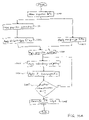
- FIG. 10A illustrates another embodiment of the reconstruction algorithm of the present invention.
- the fan-beam and cone-beam formulas for flexible range, super short-scan, short-scan or over-scan use g(s, ⁇ ) or g(s, ⁇ )) to represent the projection data shown in step 1000 of FIG. 10A for fan-beam or cone-beam data respectively.
- step 1001 projection subtraction is applied to the projection data to generate subtracted data.
- Projection subtraction is the application of the partial derivative term in the above algorithm of the present invention.
- a Hilbert filter is applied to the subtracted data to generate Hilbert-filtered data.
- a Hilbert filter or a modified Hilbert filter may be applied.
- step 1003 a ramp filter is applied to the projection data to generate ramp-filtered data.
- step 1004 the Hilbert-filtered data and the ramp-filtered data are combined to generate filtered data.
- a redundancy weighting function is applied to the filtered data.
- the redundancy weighting function w(s, ⁇ ) is not specified in the proposed reconstruction algorithms, and can be chosen freely from Parker weighting, generalized Parker weighting (MHS), Noo's weighting, over-scan weighting, quasi cone-beam weighting, and Tam window weighting ⁇ w P (s, ⁇ ), W MHS (s, ⁇ ), w N (s, ⁇ ), w OS (s, ⁇ ), W 3D (s, ⁇ ), w T ( ⁇ , v) ⁇ .
- FIG. 11 is a table that includes which weighting functions are used with which type of beam data.
- FIG. 11 shows how the algorithms of the present invention, for both fan-beam data and cone-beam data, work with different source trajectories, different detector geometries, what projection ranges can be used, what weighting functions can be used, and what filtering direction can be used.
- the projection range, ⁇ will determine the choice of weighting function.
- Cone-beam data is the same as fan-beam data, except that when the projection range is either a short-scan or an over-scan Q3D weighting can be used. Tam window weighting can also be used with cone-beam data.
- step 1006 the weighted data is subjected to a backprojection operator with an inverse distance weighting to generate an image data value.
- step 1007 a determination is made whether there are other image data values to be reconstituted in the CT image. If there are other image data values, steps 1005 - 1007 are repeated until there are no other image data values in the CT image.
- step 1008 the image data values are outputted to generate a CT image by arranging the image data values according to the points of reconstruction.
- FIG. 10B illustrates another embodiment of the reconstruction algorithm of the present invention in which image data values are reconstructed on a slice-by-slice basis.
- the fan-beam and cone-beam formulas for flexible range, super short-scan, short-scan or over-scan use g(s, ⁇ ) or g(s, ⁇ ) to represent the projection data shown in step 1000 of FIG. 10B for fan-beam or cone-beam data, respectively.
- step 1001 projection subtraction is applied to the projection data to generate subtracted data.
- Projection subtraction is the application of the partial derivative term in the above algorithm of the present invention.
- a Hilbert filter is applied to the subtracted data to generate Hilbert-filtered data.
- a Hilbert filter or a modified Hilbert filter may be applied.
- step 1003 a ramp filter is applied to the projection data to generate ramp-filtered data.
- step 1004 the Hilbert-filtered data and the ramp-filtered data are combined to generate filtered data.
- a redundancy weighting function is applied to the filtered data for a particular slice represented by a common axial (z) coordinate.
- the redundancy weighting function w(s, ⁇ ) is not specified in the proposed reconstruction algorithms, and can be chosen freely from Parker weighting, generalized Parker weighting (MHS), Noo's weighting, over-scan weighting, quasi cone-beam weighting, and Tam window weighting ⁇ w P (s, ⁇ ), W MHS (s, ⁇ ), w N (s, ⁇ ), w OS (s, ⁇ ), w 3D (s, ⁇ ), w T ( ⁇ , v) ⁇ .
- step 1006 b the weighted data is subjected to a backprojection operator with an inverse distance weighting based on the given z-coordinate of the slice to generate an image data value.
- step 1007 b a determination is made whether there are other z coordinates corresponding to other image slices to be reconstituted in the CT image volume. If there are other slices to be reconstructed, steps 1005 b - 1007 b are repeated until there are no image slices to be reconstructed in the CT image volume.
- step 1008 b the image data values in each slice are outputted to generate a CT image volume by arranging the image data values according to the points of reconstruction in each slice.
- FIG. 10C illustrates another embodiment of the reconstruction algorithm of the present invention.
- the fan-beam and cone-beam formulas for flexible range, super short-scan, short-scan or over-scan use g(s, ⁇ ) or g(s, ⁇ )) to represent the projection data shown in step 1000 of FIG. 10C for fan-beam or cone-beam data respectively.
- step 1001 projection subtraction is applied to the projection data to generate subtracted data.
- Projection subtraction is the application of the partial derivative term in the above algorithm of the present invention.
- a Hilbert filter is applied to the subtracted data to generate Hilbert-filtered data.
- a Hilbert filter or a modified Hilbert filter may be applied.
- step 1003 a ramp filter is applied to the projection data to generate ramp-filtered data.
- step 1004 the Hilbert-filtered data and the ramp-filtered data are combined to generate filtered data.
- step 1006 c the filtered data is subjected to a backprojection operator with an inverse distance weighting using a Tam window to generate an image data value.
- backprojection is restricted to filtered data contained within the Tam window only, as discussed above.
- step 1007 a determination is made whether there are other image data values to be reconstituted in the CT image. If there are other image data values, steps 1005 - 1007 are repeated until there are no other image data values in the CT image.
- step 1008 the image data values are outputted to generate a CT image by arranging the image data values according to the points of reconstruction.
- FIG. 10D illustrates a system for processing data image values in a CT image.
- CT scanning unit 951 obtains either fan-beam or cone-beam data.
- the CT scanning unit can either transfer the beam data to processor 960 or to storage unit 952 .
- Processor 960 will receive the beam data either directly from the CT scanning unit 951 or access it from storage unit 952 .
- Processor 960 in this embodiment, includes ramp filtering device 961 , projection subtraction unit 964 , Hilbert filtering unit 965 , projection addition unit 966 , weighting unit 967 , backprojection unit 962 , and outputting unit 963 .
- Projection subtraction unit 964 applies projection subtraction to the beam data that comes from either the CT scanning unit 951 or storage unit 952 to generate subtracted data.
- Hilbert filtering unit 965 then applies a Hilbert-type filter to the subtracted data to generate Hilbert-filtered data.
- Ramp filtering unit 961 applies a ramp-type filter to the beam data obtained from either CT scanning unit 951 or storage unit 952 to generate ramp filtered data.
- Projection addition unit 966 combines the ramp filtered data with the Hilbert-filtered data to generate filtered data.
- Weighting unit 967 applies a weighting function to the filtered data to generate weighted data.
- Backprojection unit 962 applies a backprojection operator with 1/L weighting to the weighted data to generate a data image value according to the points of reconstruction.
- Outputting unit 963 outputs this data image value to display 970 , storage unit 971 or both.
- the Hilbert filtering unit 965 , projection addition unit 966 , weighting unit 967 , backprojection unit 962 , and outputting unit 963 are all capable of storing and retrieving information from storage unit 952 .
- the embodiments described here can be applied with circular, helical, or saddle trajectories.
- the algorithms are independent of the geometry of the detector, i.e. equi-angular, equi-spaced, non-equi-spaced, flat, cylindrical, spherical, tilted, rotated, PI-masked, etc. can be used.
- the formulas are independent from the type of filtering lines used; horizontal, tangential, rotated, Katsevich or any other reasonable family of filtering lines. Super-short scan, short scan, over-scan, and any trajectory satisfying the completeness condition can be used.
- a reconstruction algorithm can be applied to a different source trajectory, a different detector geometry, use a different filtering direction, and use a different weighting function.
- reconstruction flow and major steps are unique for each algorithm.
- operator notation will be used. Equations for helical cone-beam geometry with redundancy weighting, which represent the most practical interest, will be compared. All formulas will be rewritten for equi-angular detector geometry. Flowcharts illustrating the algorithms below are shown in FIGS. 13A-D and an algorithm according to the present invention is shown in FIG. 10A .
- FIG. 10 and FIGS. 13A-D show a block that indicates the weighting of the backprojection for each algorithm.
- cone-beam artifact is using fan-beam redundancy weighting for helical cone-beam data.
- Using a Tam window redundancy weighting function helps significantly reduce cone-beam artifact.
- Table 1 shows which weights can be used with different algorithms.
- the speed of volume reconstruction is primarily defined by how many operations are performed in the slice reconstruction loop.
- the slice reconstruction loop for [GFDK] contains filtering, which means that the same projection is re-convolved many times for each image slice. All other algorithms are more efficient: each projection is convolved only once (for [NKDC] and [Katsevich]) or twice (for [KRND] and an embodiment of the present invention in FIG. 10A ); no re-convolutions are required.
- the [KRND] slice reconstruction loop is more complicated than [NKDC], [Katsevich], and the present invention. Note that backprojection is the most computationally demanding part of backprojection, and only one backprojection per slice cycle is strongly desired for a commercial CT reconstructor.
- Flexible reconstruction range means that any subset of the source trajectory, whose projection onto xy-plane satisfies 2D data sufficiency condition, can be used for accurate reconstruction.
- [NKDC], [KRND] and the present invention by construction have flexible reconstruction range.
- [Katsevich] does not have flexible reconstruction range since it uses Tam window weighting.
- Flexible reconstruction range also means a possibility of super-short scan. The algorithms that have this possibility are: [NKDC], [KRND] and the present invention.
- FIG. 12 shows an x-ray computed topographic imaging device that can be used to obtain data processed by methods of the present invention.
- the projection data measurement system constituted by gantry 1 accommodates an x-ray source 3 that generates a cone-beam of x-ray flux approximately cone-shaped, and a two-dimensional array type x-ray detector 5 consisting of a plurality of detector elements arranged in two-dimensional fashion, i.e., a plurality of elements arranged in one dimension stacked in a plurality of rows.
- X-ray source 3 and two-dimensional array type x-ray detector 5 are installed on a rotating ring 2 in facing opposite sides of a subject, who is laid on a sliding sheet of a bed 6 .
- Two-dimensional array type x-ray detector 5 is mounted on rotating ring 2 . Each detector element will correspond with one channel. X-rays from x-ray source 3 are directed on to subject through an x-ray filter 4 . X-rays that have passed through the subject are detected as an electrical signal by two-dimensional array type x-ray detector 5 .
- X-ray controller 8 supplies a trigger signal to high voltage generator 7 .
- High voltage generator 7 applies high voltage to x-ray source 3 with the timing with which the trigger signal is received. This causes x-rays to be emitted from x-ray source 3 .
- Gantry/bed controller 9 synchronously controls the revolution of rotating ring 2 of gantry 1 and the sliding of the sliding sheet of bed 6 .
- System controller 10 constitutes the control center of the entire system and controls x-ray controller 8 and gantry/bed controller 9 such that, as seen from the subject, x-ray source 3 executes so-called helical scanning, in which it moves along a helical path. Specifically, rotating ring 2 is continuously rotated with fixed angular speed while the sliding plate is displaced with fixed speed, and x-rays are emitted continuously or intermittently at fixed angular intervals from x-ray source 3 .
- the output signal of two-dimensional array type x-ray detector 5 is amplified by a data collection unit 11 for each channel and converted to a digital signal, to produce projection data.
- the projection data that is output from data collection unit 11 is fed to reconstruction processing unit 12 .
- Reconstruction processing unit 12 uses the projection data to find backprojection data reflecting the x-ray absorption in each voxel.
- the imaging region (effective field of view) is of cylindrical shape of radius o) centered on the axis of revolution.
- Reconstruction processing unit 12 defines a plurality of voxels (three-dimensional pixels) in this imaging region, and finds the backprojection data for each voxel.
- the three-dimensional image data or tomographic image data compiled by using this backprojection data is sent to display device 14 , where it is displayed visually as a three-dimensional image or tomographic image.
- an image to be a representation of a physical scene, in which the image has been generated by some imaging technology.
- imaging technology could include television or CCD cameras or X-ray, sonar or ultrasound imaging devices.
- the initial medium on which an image is recorded could be an electronic solid-state device, a photographic film, or some other device such as a photostimulable phosphor. That recorded image could then be converted into digital form by a combination of electronic (as in the case of a CCD signal) or mechanical/optical means (as in the case of digitizing a photographic film or digitizing the data from a photostimulable phosphor).
- the computer housing may house a motherboard that contains a CPU, memory (e.g., DRAM, ROM, EPROM, EEPROM, SRAM, SDRAM, and Flash RAM), and other optional special purpose logic devices (e.g., ASICS) or configurable logic devices (e.g., GAL and reprogrammable FPGA).
- memory e.g., DRAM, ROM, EPROM, EEPROM, SRAM, SDRAM, and Flash RAM
- other optional special purpose logic devices e.g., ASICS
- configurable logic devices e.g., GAL and reprogrammable FPGA
- the computer also includes plural input devices, (e.g., keyboard and mouse), and a display card for controlling a monitor. Additionally, the computer may include a floppy disk drive; other removable media devices (e.g. compact disc, tape, and removable magneto-optical media); and a hard disk or other fixed high density media drives, connected using an appropriate device bus (e.g., a SCSI bus, an Enhanced IDE bus, or an Ultra DMA bus).
- the computer may also include a compact disc reader, a compact disc reader/writer unit, or a compact disc jukebox, which may be connected to the same device bus or to another device bus.
- Examples of computer readable media associated with the present invention include compact discs, hard disks, floppy disks, tape, magneto-optical disks, PROMs (e.g., EPROM, EEPROM, Flash EPROM), DRAM, SRAM, SDRAM, etc.
- PROMs e.g., EPROM, EEPROM, Flash EPROM
- DRAM DRAM
- SRAM SRAM
- SDRAM Secure Digital Random Access Memory
- the present invention includes software for controlling both the hardware of the computer and for enabling the computer to interact with a human user.
- Such software may include, but is not limited to, device drivers, operating systems and user applications, such as development tools.
- Computer program products of the present invention include any computer readable medium which stores computer program instructions (e.g., computer code devices) which when executed by a computer causes the computer to perform the method of the present invention.
- the computer code devices of the present invention may be any interpretable or executable code mechanism, including but not limited to, scripts, interpreters, dynamic link libraries, Java classes, and complete executable programs. Moreover, parts of the processing of the present invention may be distributed (e.g., between (1) multiple CPUs or (2) at least one CPU and at least one configurable logic device) for better performance, reliability, and/or cost. For example, an outline or image may be selected on a first computer and sent to a second computer for remote diagnosis.
- the invention may also be implemented by the preparation of application specific integrated circuits or by interconnecting an appropriate network of conventional component circuits, as will be readily apparent to those skilled in the art.
- the source of image data to the present invention may be any appropriate image acquisition device such as an X-ray machine or CT apparatus. Further, the acquired data may be digitized if not already in digital form. Alternatively, the source of image data being obtained and processed may be a memory storing data produced by an image acquisition device, and the memory may be local or remote, in which case a data communication network, such as PACS (Picture Archiving Computer System), may be used to access the image data for processing according to the present invention.
- PACS Picture Archiving Computer System
Landscapes
- Life Sciences & Earth Sciences (AREA)
- Engineering & Computer Science (AREA)
- Health & Medical Sciences (AREA)
- Physics & Mathematics (AREA)
- Medical Informatics (AREA)
- Radiology & Medical Imaging (AREA)
- Heart & Thoracic Surgery (AREA)
- High Energy & Nuclear Physics (AREA)
- Theoretical Computer Science (AREA)
- Nuclear Medicine, Radiotherapy & Molecular Imaging (AREA)
- Optics & Photonics (AREA)
- Pathology (AREA)
- General Physics & Mathematics (AREA)
- Biomedical Technology (AREA)
- Biophysics (AREA)
- Molecular Biology (AREA)
- Surgery (AREA)
- Animal Behavior & Ethology (AREA)
- General Health & Medical Sciences (AREA)
- Public Health (AREA)
- Veterinary Medicine (AREA)
- Apparatus For Radiation Diagnosis (AREA)
- Image Processing (AREA)
- Image Generation (AREA)
- Image Analysis (AREA)
Priority Applications (5)
| Application Number | Priority Date | Filing Date | Title |
|---|---|---|---|
| US10/951,650 US7424088B2 (en) | 2004-09-29 | 2004-09-29 | Image reconstruction method using Hilbert transform |
| JP2005267253A JP5019193B2 (ja) | 2004-09-29 | 2005-09-14 | スキャン対象に関するct画像内の再構成点における画像データ値を決定する再構成方法及びx線コンピュータ断層撮影装置 |
| EP05020346A EP1643446B1 (en) | 2004-09-29 | 2005-09-19 | Image reconstruction method and x-ray computed tomography apparatus |
| DE602005001310T DE602005001310T2 (de) | 2004-09-29 | 2005-09-19 | Verfahren zur Bildrekonstruktion und Gerät zur Röntgenstrahl-Computertomografie |
| CNB2005101373058A CN100466981C (zh) | 2004-09-29 | 2005-09-29 | 图像重建方法和x射线计算机断层摄影设备 |
Applications Claiming Priority (1)
| Application Number | Priority Date | Filing Date | Title |
|---|---|---|---|
| US10/951,650 US7424088B2 (en) | 2004-09-29 | 2004-09-29 | Image reconstruction method using Hilbert transform |
Publications (2)
| Publication Number | Publication Date |
|---|---|
| US20060067457A1 US20060067457A1 (en) | 2006-03-30 |
| US7424088B2 true US7424088B2 (en) | 2008-09-09 |
Family
ID=35431883
Family Applications (1)
| Application Number | Title | Priority Date | Filing Date |
|---|---|---|---|
| US10/951,650 Expired - Fee Related US7424088B2 (en) | 2004-09-29 | 2004-09-29 | Image reconstruction method using Hilbert transform |
Country Status (5)
| Country | Link |
|---|---|
| US (1) | US7424088B2 (ja) |
| EP (1) | EP1643446B1 (ja) |
| JP (1) | JP5019193B2 (ja) |
| CN (1) | CN100466981C (ja) |
| DE (1) | DE602005001310T2 (ja) |
Cited By (8)
| Publication number | Priority date | Publication date | Assignee | Title |
|---|---|---|---|---|
| US20100158194A1 (en) * | 2008-12-22 | 2010-06-24 | General Electric Company | System and method for image reconstruction |
| US20120014582A1 (en) * | 2009-03-26 | 2012-01-19 | Koninklijke Philips Electronics N.V. | Method and apparatus for computed tomography image reconstruction |
| US20120063659A1 (en) * | 2009-04-15 | 2012-03-15 | Virginia Tech Intellectual Properties, Inc | Exact local computed tomography based on compressive sampling |
| US8204172B1 (en) * | 2010-03-17 | 2012-06-19 | General Electric Company | System and method of prior image constrained image reconstruction using short scan image data and objective function minimization |
| US20120301001A1 (en) * | 2011-05-24 | 2012-11-29 | Siemens Aktiengesellschaft | Method and computed tomography system for generating tomographic image datasets |
| US8805037B2 (en) | 2011-05-31 | 2014-08-12 | General Electric Company | Method and system for reconstruction of tomographic images |
| US8948337B2 (en) | 2013-03-11 | 2015-02-03 | General Electric Company | Computed tomography image reconstruction |
| US9510787B2 (en) * | 2014-12-11 | 2016-12-06 | Mitsubishi Electric Research Laboratories, Inc. | Method and system for reconstructing sampled signals |
Families Citing this family (33)
| Publication number | Priority date | Publication date | Assignee | Title |
|---|---|---|---|---|
| EP1828986A2 (en) * | 2004-11-24 | 2007-09-05 | Wisconsin Alumni Research Foundation | Cone-beam filtered backprojection image reconstruction method for short trajectories |
| US7251307B2 (en) * | 2004-11-24 | 2007-07-31 | Wisconsin Alumni Research Foundation | Fan-beam and cone-beam image reconstruction using filtered backprojection of differentiated projection data |
| US20060198491A1 (en) * | 2005-03-04 | 2006-09-07 | Kabushiki Kaisha Toshiba | Volumetric computed tomography system for imaging |
| CN101175439B (zh) * | 2005-05-12 | 2010-05-26 | 皇家飞利浦电子股份有限公司 | 执行超短扫描和对最新数据的更强加权的连续计算机层析成像 |
| US7653230B2 (en) * | 2006-02-21 | 2010-01-26 | General Electric Company | Methods and systems for image reconstruction using low noise kernel |
| US7409033B2 (en) * | 2006-05-31 | 2008-08-05 | The Board Of Trustees Of The Leland Stanford Junior University | Tomographic reconstruction for x-ray cone-beam scan data |
| WO2008064367A2 (en) * | 2006-11-24 | 2008-05-29 | Kabushiki Kaisha Toshiba | Method and system for tomographic reconstruction in medical imaging using the circle and line trajectory |
| JP5426075B2 (ja) | 2007-01-31 | 2014-02-26 | 株式会社東芝 | X線ct装置 |
| JP2009022450A (ja) * | 2007-07-18 | 2009-02-05 | Ge Medical Systems Global Technology Co Llc | X線ct装置および画像作成方法 |
| US8494111B2 (en) * | 2007-11-02 | 2013-07-23 | Kabushiki Kaisha Toshiba | System and method for image reconstruction for helical cone beam computed tomography with factorized redundancy weighting |
| DE102007054371B4 (de) * | 2007-11-14 | 2014-09-04 | Siemens Aktiengesellschaft | Verfahren zur Bilddarstellung von Projektionsdaten |
| US7792238B2 (en) * | 2008-02-18 | 2010-09-07 | General Electric Company | Method and system for reconstructing cone-beam projection data with reduced artifacts |
| DE112009005019B4 (de) | 2009-06-30 | 2022-02-03 | Analogic Corp. | Effizienter quasi-exakter 3D Bildrekonstruktionsalgorithmus für CTScanner |
| JP5433334B2 (ja) * | 2009-07-27 | 2014-03-05 | 株式会社東芝 | X線ct装置 |
| EP2315178A1 (en) * | 2009-10-12 | 2011-04-27 | Siemens Aktiengesellschaft | Reconstruction of 3D image datasets from X-ray cone-beam data |
| US8824760B2 (en) * | 2009-10-20 | 2014-09-02 | University Of Utah Research Foundation | Modification and elimination of back projection weight during the CT image reconstruction |
| US8731266B2 (en) * | 2009-12-17 | 2014-05-20 | General Electric Company | Method and system for correcting artifacts in image reconstruction |
| DE102010020770A1 (de) * | 2010-05-17 | 2011-11-17 | Siemens Aktiengesellschaft | Verfahren zur Reduzierung von Bildartefakten, insbesondere von Metallartefakten, in CT-Bilddaten |
| DE102011076547A1 (de) * | 2011-05-26 | 2012-11-29 | Siemens Aktiengesellschaft | Verfahren zum Gewinnen eines 3D-Bilddatensatzes zu einem Bildobjekt |
| US9076255B2 (en) * | 2011-05-31 | 2015-07-07 | General Electric Company | Method and system for reconstruction of tomographic images |
| US8837797B2 (en) * | 2012-01-10 | 2014-09-16 | Kabushiki Kaisha Toshiba | Spatial resolution improvement in computer tomography (CT) using iterative reconstruction |
| CN102590243B (zh) * | 2012-02-17 | 2013-09-04 | 重庆大学 | 一种铁路铸件全身ct扫描成像方法 |
| US8798350B2 (en) * | 2012-03-22 | 2014-08-05 | Kabushiki Kaisha Toshiba | Method and system for reconstruction algorithm in cone beam CT with differentiation in one direction on detector |
| KR20150022176A (ko) | 2013-08-22 | 2015-03-04 | 삼성전자주식회사 | 영상 처리 유닛, 영상 재구성 방법 및 방사선 영상 장치 |
| CN103714560B (zh) * | 2013-12-27 | 2016-10-05 | 哈尔滨工业大学深圳研究生院 | 一种基于Katsevich算法的图像重建方法和系统 |
| CN110897590B (zh) | 2014-03-28 | 2021-11-16 | 直观外科手术操作公司 | 带有基于定量三维成像的触觉反馈的手术系统 |
| CN110251047B (zh) * | 2014-03-28 | 2022-01-18 | 直观外科手术操作公司 | 手术植入物的定量三维成像和打印 |
| CN106456267B (zh) | 2014-03-28 | 2020-04-03 | 直观外科手术操作公司 | 器械在视野中的定量三维可视化 |
| CN106097411B (zh) * | 2016-06-29 | 2019-07-05 | 沈阳开普医疗影像技术有限公司 | Ct机图像重建方法及高分辨ct扫描机 |
| CN110337672B (zh) * | 2016-12-21 | 2024-01-16 | 皇家飞利浦有限公司 | 用于短扫描偏心探测器x射线断层摄影的冗余度加权 |
| WO2019033390A1 (en) * | 2017-08-18 | 2019-02-21 | Shenzhen United Imaging Healthcare Co., Ltd. | SYSTEM AND METHOD FOR IMAGE RECONSTRUCTION |
| GB2599301B (en) * | 2019-05-10 | 2023-05-31 | Koninklijke Philips Nv | Cone beam artifact correction for gated imaging |
| CN111489408B (zh) * | 2020-04-21 | 2022-11-11 | 赛诺威盛科技(北京)股份有限公司 | 基于重叠3d半扫描数据的ct图像重建方法及装置、终端 |
Citations (1)
| Publication number | Priority date | Publication date | Assignee | Title |
|---|---|---|---|---|
| US6990167B2 (en) * | 2003-08-29 | 2006-01-24 | Wisconsin Alumni Research Foundation | Image reconstruction method for divergent beam scanner |
Family Cites Families (10)
| Publication number | Priority date | Publication date | Assignee | Title |
|---|---|---|---|---|
| US5926521A (en) * | 1998-03-31 | 1999-07-20 | Siemens Corporate Research, Inc. | Exact region of interest cone beam imaging using 3D backprojection |
| US6018561A (en) * | 1998-07-27 | 2000-01-25 | Siemens Corporate Research, Inc. | Mask boundary correction in a cone beam imaging system using simplified filtered backprojection image reconstruction |
| US6452996B1 (en) * | 2001-03-16 | 2002-09-17 | Ge Medical Systems Global Technology Company, Llc | Methods and apparatus utilizing generalized helical interpolation algorithm |
| US6574299B1 (en) * | 2001-08-16 | 2003-06-03 | University Of Central Florida | Exact filtered back projection (FBP) algorithm for spiral computer tomography |
| DE10155590A1 (de) * | 2001-11-13 | 2003-05-15 | Philips Corp Intellectual Pty | Fluoroskopisches Computertomographie-Verfahren |
| JP3950782B2 (ja) * | 2002-05-22 | 2007-08-01 | ジーイー・メディカル・システムズ・グローバル・テクノロジー・カンパニー・エルエルシー | 3次元逆投影方法およびx線ct装置 |
| JP4030827B2 (ja) * | 2002-08-13 | 2008-01-09 | ジーイー・メディカル・システムズ・グローバル・テクノロジー・カンパニー・エルエルシー | 投影データ作成方法、画素データ作成方法およびマルチ検出器x線ct装置 |
| DE10248766B4 (de) * | 2002-10-18 | 2005-02-10 | Siemens Ag | Verfahren zur Bilderstellung für einen mehrzeiligen Spiral-Computertomographen und Computer-Tomographie-Gerät zur Durchführung dieses Verfahrens |
| DE10304662A1 (de) * | 2003-02-05 | 2004-08-19 | Siemens Ag | Verfahren zur Erzeugung von Bildern in der Computertomographie mit einem 3D-Bildrekonstruktionsverfahren |
| CN100359537C (zh) * | 2003-02-19 | 2008-01-02 | 皇家飞利浦电子股份有限公司 | 利用螺旋相对运动和锥形光束的计算机化x线断层摄影方法 |
-
2004
- 2004-09-29 US US10/951,650 patent/US7424088B2/en not_active Expired - Fee Related
-
2005
- 2005-09-14 JP JP2005267253A patent/JP5019193B2/ja active Active
- 2005-09-19 EP EP05020346A patent/EP1643446B1/en not_active Expired - Fee Related
- 2005-09-19 DE DE602005001310T patent/DE602005001310T2/de active Active
- 2005-09-29 CN CNB2005101373058A patent/CN100466981C/zh not_active Expired - Fee Related
Patent Citations (1)
| Publication number | Priority date | Publication date | Assignee | Title |
|---|---|---|---|---|
| US6990167B2 (en) * | 2003-08-29 | 2006-01-24 | Wisconsin Alumni Research Foundation | Image reconstruction method for divergent beam scanner |
Non-Patent Citations (20)
| Title |
|---|
| A. Katsevich, "Analysis of an Exact Inversion Algorithm for Spiral Cone-Beam CT," Physics in Medicine and Biology. 2002, vol. 47, pp. 2583-2598, 14 pages. |
| A. Katsevich, "Theoretically Exact FBP-Type Inversion Algorithm for Spiral CT," The Sixth International Meeting on Fully Three-Dimensional Image Reconstruction in Radiology and Nuclear Medicine, Pacific Grove, CA, USA, Oct.-Nov. 2001, 4 pages. |
| A. Katsevich, et al., "Analysis of a Family of Exact Inversion Formulas for Cone Beam CT," Department of Mathematics, University of Central Florida, pp. 1-13. |
| Alexander A. Zamyatin, et al., "Practical Hybrid Convolution Algorithm for Helical CT Reconstruction," supported by Toshiba Medical Systems, 2004, 5 pages. |
| Alexander Katsevich, "Improved Exact FBP Algorithm for Spiral CT," Department of Mathematics, University of Central Florida, pp. 1-19. |
| Alexander Zamyatin, "Analysis of Cone Beam Reconstruction in Computer Tomography," Department of Mathematics, University of Central Florida, Fall Term 2003, pp. i-viii and 1-69. |
| Carl R. Crawford, et al., "Computed Tomography Scanning with Simultaneous Patient Translation," Medical Physics, vol. 17, No. 6, Nov./Dec. 1990, pp. 967-982. |
| Chen, Guang-Hong, A new framework of image reconstruction from fan beam projections, Med. Phys. 30 (6), Jun. 2003, p. 1151-1161. * |
| Chen, Guang-Hong, An alternative derivation of Katsevich's cone-beam reconstruction formula, Med. Phys. 30 (12), Dec. 2003, p. 3217-3226. * |
| F. Noo, et al., "Image Reconstruction from Fan-Beam Projections on Less Than a Short Scan," Physics in Medicine and Biology, vol. 47, 2002, pp. 2525-2546. |
| Ge Wang, et al., "A General Cone-Beam Reconstruction Algorithm," IEEE Transactions on Medical Imaging, vol. 12, No. 3, Sep. 1993, pp. 486-496. |
| H. Kudo, et al., "New Super-Short Scan Algorithms for Fan Beam and Cone-Beam Reconstruction," Conference Record of 2002 IEEE Nuclear Science Symposium and Medical Imaging Conference (paper M5-3, CD-ROM, ISBN 0-7803-7637-4), 5 pages. |
| Hiroyuki Kudo, et al., "Exact and Approximate Algorithms for Helical Cone-Beam CT," Institute of Physics Publishing, Physics in Medicine and Biology, vol. 49, 2004, pp. 2913-2931. |
| Jed D. Pack, et al., "Investigation of Saddle Trajectories for Cardiac CT Imaging in Cone-Beam Geometry," Institute Physics Publishing, Physics in Medicine and Biology, vol. 49, 2004, pp. 2317-2336. |
| Katsuyuki Taguchi, "Temporal Resolution and the Evaluation of Candidate Algorithms for Four-Dimensional CT," Medical Physics vol. 30, No. 4, Apr. 2003, pp. 640-650. |
| Katsuyuki Taguchi, et al., "A New Weighting Scheme for Cone-Beam Helical CT to Reduce the Image Noise," Institute of Physics Publishing, Physics in Medicine and Biology, vol. 49, 2004, pp. 2351-2364. |
| L. A. Feldkamp, et al., "Practical Cone-Beam Algorithm," Optical Society of America, vol. 1, No. 6, Jun. 1984, pp. 612-619. |
| Michael D. Silver, "A Method for Including Redundant Data in Computed Tomography," Medical Physics, vol. 27, No. 4, Apr. 2000, pp. 773-774. |
| Michael D. Silver, "Field-of-View Dependent Helical in Multi-Slice CT," Proceedings of SPIE vol. 4320, 2001, pp. 839-850. |
| Per-Erik Danielsson, et al., "The PI-Methods for Helical Cone-Beam Tomography," Physics in Medicine and Biology, Dec. 2001, pp. 1-14. |
Cited By (12)
| Publication number | Priority date | Publication date | Assignee | Title |
|---|---|---|---|---|
| US20100158194A1 (en) * | 2008-12-22 | 2010-06-24 | General Electric Company | System and method for image reconstruction |
| US8284892B2 (en) | 2008-12-22 | 2012-10-09 | General Electric Company | System and method for image reconstruction |
| US20120014582A1 (en) * | 2009-03-26 | 2012-01-19 | Koninklijke Philips Electronics N.V. | Method and apparatus for computed tomography image reconstruction |
| US8787646B2 (en) * | 2009-03-26 | 2014-07-22 | Koninklijke Philips N.V. | Method and apparatus for computed tomography image reconstruction |
| US20120063659A1 (en) * | 2009-04-15 | 2012-03-15 | Virginia Tech Intellectual Properties, Inc | Exact local computed tomography based on compressive sampling |
| US8811700B2 (en) * | 2009-04-15 | 2014-08-19 | Virginia Tech Intellectual Properties, Inc. | Exact local computed tomography based on compressive sampling |
| US8204172B1 (en) * | 2010-03-17 | 2012-06-19 | General Electric Company | System and method of prior image constrained image reconstruction using short scan image data and objective function minimization |
| US20120301001A1 (en) * | 2011-05-24 | 2012-11-29 | Siemens Aktiengesellschaft | Method and computed tomography system for generating tomographic image datasets |
| US8897531B2 (en) * | 2011-05-24 | 2014-11-25 | Siemens Aktiengesellschaft | Method and computed tomography system for generating tomographic image datasets with integrating detector and counting detector |
| US8805037B2 (en) | 2011-05-31 | 2014-08-12 | General Electric Company | Method and system for reconstruction of tomographic images |
| US8948337B2 (en) | 2013-03-11 | 2015-02-03 | General Electric Company | Computed tomography image reconstruction |
| US9510787B2 (en) * | 2014-12-11 | 2016-12-06 | Mitsubishi Electric Research Laboratories, Inc. | Method and system for reconstructing sampled signals |
Also Published As
| Publication number | Publication date |
|---|---|
| CN1788684A (zh) | 2006-06-21 |
| EP1643446B1 (en) | 2007-06-06 |
| CN100466981C (zh) | 2009-03-11 |
| JP2006095297A (ja) | 2006-04-13 |
| EP1643446A1 (en) | 2006-04-05 |
| JP5019193B2 (ja) | 2012-09-05 |
| DE602005001310T2 (de) | 2008-01-31 |
| DE602005001310D1 (de) | 2007-07-19 |
| US20060067457A1 (en) | 2006-03-30 |
Similar Documents
| Publication | Publication Date | Title |
|---|---|---|
| US7424088B2 (en) | Image reconstruction method using Hilbert transform | |
| US8270559B2 (en) | Method and system for tomographic reconstruction in medical imaging using the circle and line trajectory | |
| US7251307B2 (en) | Fan-beam and cone-beam image reconstruction using filtered backprojection of differentiated projection data | |
| EP1489559B1 (en) | Cone-beam reconstruction apparatus and computed tomography apparatus | |
| US8630472B2 (en) | Increased temporal resolution in the case of CT images by means of iterative view reconstruction with limiting conditions | |
| US7403587B2 (en) | Computer tomography method using a cone-shaped bundle of rays | |
| US7359478B2 (en) | Method for restoring truncated helical cone-beam computed tomography data | |
| US6904117B2 (en) | Tilted gantry helical cone-beam Feldkamp reconstruction for multislice CT | |
| Bruder et al. | Single-slice rebinning reconstruction in spiral cone-beam computed tomography | |
| EP1372115B1 (en) | Methods and apparatus for reconstructing an image of an object | |
| Turbell et al. | Helical cone‐beam tomography | |
| US7050527B2 (en) | Methods and apparatus for artifact reduction in cone beam CT image reconstruction | |
| JP2001212130A (ja) | マルチ・スライスの単一回フィルタ処理及び螺旋加重方法と、該方法を用いた装置 | |
| US20050226365A1 (en) | Radius-in-image dependent detector row filtering for windmill artifact reduction | |
| JP3788846B2 (ja) | X線コンピュータ断層撮影装置 | |
| JP2002034970A (ja) | マルチ・スライスct走査の螺旋再構成の方法及び装置 | |
| US8131042B2 (en) | Methods and apparatus for hybrid cone beam image reconstruction | |
| US6999550B2 (en) | Method and apparatus for obtaining data for reconstructing images of an object | |
| Shechter et al. | The frequency split method for helical cone‐beam reconstruction | |
| US7173996B2 (en) | Methods and apparatus for 3D reconstruction in helical cone beam volumetric CT | |
| Shechter et al. | High-resolution images of cone beam collimated CT scans | |
| JP2772289B2 (ja) | コンピュータ断層撮影装置 | |
| Jiang | Implementierung und Evaluation von 3D Rekonstruktions-Algorithmen für Dedizierte Brust CT | |
| Hu et al. | A simple derivation and analysis of a helical cone beam tomographic algorithm for long object imaging via a novel definition of region of interest | |
| Yu et al. | A rebinning-type backprojection-filtration algorithm for image reconstruction in helical cone-beam CT |
Legal Events
| Date | Code | Title | Description |
|---|---|---|---|
| AS | Assignment |
Owner name: TOSHIBA MEDICAL SYSTEMS CORPORATION, JAPAN Free format text: ASSIGNMENT OF ASSIGNORS INTEREST;ASSIGNORS:ZAMYATIN, ALEKSANDR A.;TAGUCHI, KATSUYUKI;REEL/FRAME:016180/0016 Effective date: 20041111 Owner name: KABUSHIKI KAISHA TOSHIBA, JAPAN Free format text: ASSIGNMENT OF ASSIGNORS INTEREST;ASSIGNORS:ZAMYATIN, ALEKSANDR A.;TAGUCHI, KATSUYUKI;REEL/FRAME:016180/0016 Effective date: 20041111 |
|
| STCF | Information on status: patent grant |
Free format text: PATENTED CASE |
|
| FPAY | Fee payment |
Year of fee payment: 4 |
|
| FPAY | Fee payment |
Year of fee payment: 8 |
|
| AS | Assignment |
Owner name: TOSHIBA MEDICAL SYSTEMS CORPORATION, JAPAN Free format text: ASSIGNMENT OF ASSIGNORS INTEREST;ASSIGNOR:KABUSHIKI KAISHA TOSHIBA;REEL/FRAME:038891/0693 Effective date: 20160316 |
|
| FEPP | Fee payment procedure |
Free format text: MAINTENANCE FEE REMINDER MAILED (ORIGINAL EVENT CODE: REM.); ENTITY STATUS OF PATENT OWNER: LARGE ENTITY |
|
| LAPS | Lapse for failure to pay maintenance fees |
Free format text: PATENT EXPIRED FOR FAILURE TO PAY MAINTENANCE FEES (ORIGINAL EVENT CODE: EXP.); ENTITY STATUS OF PATENT OWNER: LARGE ENTITY |
|
| STCH | Information on status: patent discontinuation |
Free format text: PATENT EXPIRED DUE TO NONPAYMENT OF MAINTENANCE FEES UNDER 37 CFR 1.362 |
|
| FP | Lapsed due to failure to pay maintenance fee |
Effective date: 20200909 |