US7289397B2 - Method and apparatus for determining position of optical pick-up head - Google Patents
Method and apparatus for determining position of optical pick-up head Download PDFInfo
- Publication number
- US7289397B2 US7289397B2 US10/906,982 US90698205A US7289397B2 US 7289397 B2 US7289397 B2 US 7289397B2 US 90698205 A US90698205 A US 90698205A US 7289397 B2 US7289397 B2 US 7289397B2
- Authority
- US
- United States
- Prior art keywords
- pick
- head
- optical storage
- storage medium
- determining
- Prior art date
- Legal status (The legal status is an assumption and is not a legal conclusion. Google has not performed a legal analysis and makes no representation as to the accuracy of the status listed.)
- Expired - Fee Related, expires
Links
Images


Classifications
-
- G—PHYSICS
- G11—INFORMATION STORAGE
- G11B—INFORMATION STORAGE BASED ON RELATIVE MOVEMENT BETWEEN RECORD CARRIER AND TRANSDUCER
- G11B27/00—Editing; Indexing; Addressing; Timing or synchronising; Monitoring; Measuring tape travel
- G11B27/10—Indexing; Addressing; Timing or synchronising; Measuring tape travel
- G11B27/19—Indexing; Addressing; Timing or synchronising; Measuring tape travel by using information detectable on the record carrier
- G11B27/28—Indexing; Addressing; Timing or synchronising; Measuring tape travel by using information detectable on the record carrier by using information signals recorded by the same method as the main recording
- G11B27/30—Indexing; Addressing; Timing or synchronising; Measuring tape travel by using information detectable on the record carrier by using information signals recorded by the same method as the main recording on the same track as the main recording
- G11B27/3027—Indexing; Addressing; Timing or synchronising; Measuring tape travel by using information detectable on the record carrier by using information signals recorded by the same method as the main recording on the same track as the main recording used signal is digitally coded
- G11B27/3063—Subcodes
-
- G—PHYSICS
- G11—INFORMATION STORAGE
- G11B—INFORMATION STORAGE BASED ON RELATIVE MOVEMENT BETWEEN RECORD CARRIER AND TRANSDUCER
- G11B27/00—Editing; Indexing; Addressing; Timing or synchronising; Monitoring; Measuring tape travel
- G11B27/10—Indexing; Addressing; Timing or synchronising; Measuring tape travel
- G11B27/19—Indexing; Addressing; Timing or synchronising; Measuring tape travel by using information detectable on the record carrier
- G11B27/24—Indexing; Addressing; Timing or synchronising; Measuring tape travel by using information detectable on the record carrier by sensing features on the record carrier other than the transducing track ; sensing signals or marks recorded by another method than the main recording
-
- G—PHYSICS
- G11—INFORMATION STORAGE
- G11B—INFORMATION STORAGE BASED ON RELATIVE MOVEMENT BETWEEN RECORD CARRIER AND TRANSDUCER
- G11B7/00—Recording or reproducing by optical means, e.g. recording using a thermal beam of optical radiation by modifying optical properties or the physical structure, reproducing using an optical beam at lower power by sensing optical properties; Record carriers therefor
- G11B7/08—Disposition or mounting of heads or light sources relatively to record carriers
- G11B7/085—Disposition or mounting of heads or light sources relatively to record carriers with provision for moving the light beam into, or out of, its operative position or across tracks, otherwise than during the transducing operation, e.g. for adjustment or preliminary positioning or track change or selection
- G11B7/08505—Methods for track change, selection or preliminary positioning by moving the head
-
- G—PHYSICS
- G11—INFORMATION STORAGE
- G11B—INFORMATION STORAGE BASED ON RELATIVE MOVEMENT BETWEEN RECORD CARRIER AND TRANSDUCER
- G11B2220/00—Record carriers by type
- G11B2220/20—Disc-shaped record carriers
- G11B2220/21—Disc-shaped record carriers characterised in that the disc is of read-only, rewritable, or recordable type
- G11B2220/215—Recordable discs
- G11B2220/218—Write-once discs
-
- G—PHYSICS
- G11—INFORMATION STORAGE
- G11B—INFORMATION STORAGE BASED ON RELATIVE MOVEMENT BETWEEN RECORD CARRIER AND TRANSDUCER
- G11B2220/00—Record carriers by type
- G11B2220/20—Disc-shaped record carriers
- G11B2220/25—Disc-shaped record carriers characterised in that the disc is based on a specific recording technology
- G11B2220/2537—Optical discs
- G11B2220/2545—CDs
Definitions
- the present invention relates to a method and an apparatus for determining the position of a pick-up head (PUH), more particularly to a method and an apparatus for correctly determining the current position of the pick-up head according to the velocity-related values of the pick-up head at a certain position on an optical storage medium.
- PH pick-up head
- FIG. 1 is a schematic diagram illustrating the information area structure of a quarter of a conventional optical storage medium.
- an optical storage medium 10 for example, an optical disk like the CD-R format or the CD-RW format
- the information area of the optical storage medium 10 is sequentially divided into a laser power calibration area (PCA) 12 , a program memory area (PMA) 13 , a lead-in (LI) area 14 , a program area (PA) 15 and a lead-out (LO) area 16 from its interior to its exterior.
- PCA laser power calibration area
- PMA program memory area
- LI lead-in
- PA program area
- LO lead-out
- the shallow groove starts from the center of the optical storage medium and is spirally formed thereon by means of a laser beam controlled by a predetermined program.
- a pre-groove the groove does not look like a smooth spiral, but instead is a spiral that wobbles in a sinusoidal waveform of tiny amplitude.
- a signal read from the pre-groove is hereinafter referred to as a “wobble signal.” Every sector on an optical disk generally fabricated by die-casting contains time-related data for controlling the rotational speed of an optical storage device, in order to correctly read signals recorded on the optical disk.
- a recordable optical storage device It is necessary for a recordable optical storage device to guide the laser beam of the pick-up head to move outward in proper sequence and control its rotational speed correctly according to some means. Since the tracking and timing code information is provided by the wobbling pre-groove, such information is called ATIP (Absolute Time In Pre-groove) data. With the data, the recording speed of signals can be kept constant.
- the optical storage device adds the address information to the main data, and then the combined data are encoded and scrambled before the processed main data converted by Eight-to-Fourteen Modulation (hereinafter referred to as “EFM signals”) are recorded on the tracks of the recordable optical disk.
- EFM signals Eight-to-Fourteen Modulation
- the optical storage device demodulates the EFM signals first and then descrambles and decodes them in order to read the main data and address information. If the EFM signals burned to an optical disk are present, the optical storage device can use such signals to make the optical pick-up head move in proper sequence and control the rotational speed of a spindle motor. On the other hand, after the signals are successfully decoded, the physical address information required for the positioning of the pick-up head can be obtained.
- FIG. 2 is a diagram illustrating the scheme of ATIP data.
- the ATIP data comprises a 4-bit sync code, an 8-bit minute (M) code, an 8-bit second (S) code, an 8-bit frame (F) code, and a cyclic redundancy check code (CRC).
- ATIP time codes ⁇ MM: SS: FF ⁇ can define the absolute beginning and the absolute destination of every sub area in an information area of an optical disk and are obtained through the minute codes, second codes, and frame codes; wherein MM, SS and FF denote the minute code (0-99), second code (0-59), and frame code (0-74), respectively.
- FIG. 3 is a diagram illustrating the corresponding relationship between an information area and an ATIP time code.
- t 1 denotes the start time code of the laser beam power calibration area (PCA) 12 , which is set to ⁇ 95:00:00 ⁇ in most optical disks
- t 2 denotes the start time code of the program memory area (PMA) 13
- t 3 denotes the start time code of the lead-in area (LI) 14
- t 4 may preferably denote the end time code ⁇ 99:59:74 ⁇ of the lead-in area (LI) 14 or the start time code ⁇ 00:00:00 ⁇ of the program area (PA) 15
- t 5 denotes the last possible start time code of the lead-out area (LO) 16 , for example, an 80-minute CD-R disk designates t 5 as ⁇ 79:59:74 ⁇ .
- the program area (PA) 15 of an optical disk it is quite common for the program area (PA) 15 of an optical disk to have a capacity greater than 95 minutes, and in consequence it is impossible to map time codes one-to-one and onto the locations of the various areas in the optical disk, as shown in FIG. 4 .
- an interval of the time code from ⁇ 95:00:00 ⁇ to ⁇ 99:59:74 ⁇ can be mapped to two different areas, thus it is impossible to determine the exact position of the pick-up head, as far as its whereabouts is concerned, using the ATIP time code extracted from ATIP information; in other words, the exact position of the pick-up head is necessarily determined by an auxiliary means, such as the other conditions or data.
- FIG. 5 is a diagram about the structure of subcode-Q data in mode 1 .
- An ADR (address) of 1h indicates mode 1 , wherein h denotes a hexadecimal number.
- a TNO (track number) of 00h indicates that the subcode-Q data is stored at the lead-in area disposed in the innermost tracks. On the contrary, if the TNO is not equal to 00h, the corresponding subcode-Q data may be stored in a program area or a lead-out area. Hence, it is possible to determine the current position of the pick-up head by reading the information of the subcode-Q data with a logic program executed during tracking.
- optical disks are divided into two types, namely single-session and multi-session, as shown in FIGS. 6( a ) and 6 ( b ).
- a single-session optical disk 61 can be written once only and thus its data structure is simple; as a result, a TNO of 00h indicates that the subcode-Q data is stored in the lead-in area disposed in the innermost tracks.
- a multi-session optical disk 62 it is impossible to determine whether the pick-up head is currently located in a lead-in area (LI) between two program areas (PA) or in the innermost lead-in area (LI), even if the TNO equals 00h.
- predetermined functions of an optical disk drive such as reading recorded data, writing data, reading data of a TOC (table of contents) from a lead-in area, and reading data of PMA, are achieved by the execution of various procedures which depend on the need, as far as the operation and application of the optical disk are concerned.
- a seeking-and-tracking servo control circuit is always called first to move the pick-up as long as the functions attempt to read/write data from/to the optical disk. After the pick-up head moves to a target area, it executes extracting or writing data from or to the target area through following tracks.
- the mechanism of seeking is that the seeking-and-tracking servo control circuit reads the present address (acquired by means of the ATIP time code or the subcode-Q data) to confirm the “current position” first after a caller, such as a function which is attempting to read the data stored at the target position, gives a command of getting to a “target position”; then, the jumping direction and distance crossing the track direction are calculated in the light of the relationship between the current position and the target position, and the jumping action is executed in accordance with the result of the calculation. Track is locked again when the jumping action is done, though it entails reading the present address once again in order to confirm whether the pick-up head reaches the target area. If the arrival of the pick-up head at the target area is confirmed, the seeking action ends; otherwise, the seeking action continues in the light of the relationship between the current position and the target position until the pick-up head reaches the predetermined target area.
- the optical storage device is unable to determine the current position solely by means of the ATIP time code or the subcode-Q data, as it is still necessary to set an area flag that indicates whether the position is or not in a specified area for determining some positions which correspond to overlapped time codes.
- the data of the area flag have to be checked out or reset whenever a different application procedure is executed, and auxiliary conditions are continually renewed and judged in the light of variations in the positions of the pick-up head predicted by individual application procedures.
- program maintenance is difficult, while omissions are common, especially that the movements of pick-up head are different and complex for many kinds of purposes and operation sequences for optical devices; as a result, any ensuing judgment is indefinite.
- the complicated examination and configuration which are taking place in the area flag and auxiliary conditions inevitably decrease the execution efficiency of the entire system, not to mention that such an additional confirmation program has not been applied to all optical disks with different formats yet.
- the primary objective of the present invention is to provide a method and an apparatus for determining the position of a pick-up head, wherein the current position of the pick-up head is accurately determined in the light of detected signals or information relating to the linear velocity or angular velocity of the pick-up head at a certain place on an optical disk.
- the second objective of the present invention is to provide a method for determining the current position of the pick-up head in the light of absolute conditions, without adding position determining auxiliary conditions or programs to various procedures. As a result, logical judgment mistakes are unlikely to happen, while system execution efficiency of the optical storage device increases.
- the present invention discloses a method and an apparatus for determining the position of a pick-up head, and it involves retrieving the respective signals or information relating to the linear velocity and angular velocity of the pick-up head at a certain place on the optical disk, and then calculating the ratio of the obtained parameter of the linear velocity to the obtained parameter of the angular velocity. Since the ratio is linearly correlated with the distance between the pick-up head and the center of the optical disk, the absolute position of the pick-up head can be determined, as far as its whereabouts is concerned.
- the absolute position of the pick-up head can be determined in the light of the signals or information relating to the angular velocity of the pick-up head, as far as its whereabouts is concerned.
- the absolute position of the pick-up head can be determined in the light of the signals or information relating to the linear velocity of the pick-up head, as far as its whereabouts is concerned.
- FIG. 1 is a schematic diagram illustrating the information area structure of a quarter of a conventional optical storage medium
- FIG. 2 is a diagram illustrating the scheme of ATIP data
- FIG. 3 is a diagram illustrating the corresponding relationship between an information area and an ATIP time code
- FIG. 4 is a graph of corresponding relationships between the program area of an optical disk and ATIP time code
- FIG. 5 is a diagram about the structure of subcode-Q data in mode 1 ;
- FIG. 6( a ) is a schematic diagram illustrating the scheme of a single-session optical disk
- FIG. 6( b ) is a schematic diagram illustrating the scheme of a multi-session optical disk
- FIG. 7( a ) is a schematic diagram illustrating a light spot from an optical pick-up head focused on an optical disk
- FIG. 7( b ) is a schematic diagram illustrating how an optical disk rotates at a constant linear velocity (CLV) mode
- FIG. 7( c ) is a schematic diagram illustrating how an optical disk rotates at a constant angular velocity (CAV) mode
- FIGS. 8-8( c ) are flowcharts about how the current position of a pick-up head is determined in accordance with the present invention.
- FIG. 9 is a functional block diagram of the apparatus for determining the current position of a pick-up head in accordance with the present invention.
- FIG. 7( a ) is a schematic diagram illustrating a light spot from an optical pick-up head focused on an optical disk.
- the light spot of the pick-up head is focused on a point P of the optical disk 10
- V P denotes the linear velocity at the point P
- ⁇ P denotes the angular velocity of the optical disk 10 .
- the linear velocity V P and the angular velocity cop are known for the optical storage device, thus the distance ⁇ P between the center O of the optical disk 10 and the point P is obtained from the following equation:
- the linear velocity V P is figured out, using a wobble signal or an EFM signal, while the angular velocity ⁇ P is directly derived from the rotation speed of a spindle motor.
- the absolute position of the pick-up head can be figured out once the area of the current position is determined by means of r P , without identifying the rotation mode of the spindle motor.
- any other equivalent signals or electric parameters relating to the angular velocity as input signal—for example an input/output voltage or a current for the control of spindle rotation speed or frequency.
- FIG. 7( b ) is a schematic diagram illustrating how an optical disk rotates at a constant linear velocity (CLV) mode.
- V 1 denotes the linear velocity at the point A
- ⁇ 1 denotes the angular velocity of the optical disk 10 at the point A.
- V 2 denotes the linear velocity at the point B
- ⁇ 2 denotes the angular velocity of the optical disk 10 at the point B.
- the distances between the center O of the optical disk 10 and the points A and B are denoted by r 1 and r 2 , respectively.
- FIG. 7( c ) is a schematic diagram illustrating how an optical disk rotates at a constant angular velocity (CAV) mode.
- V 1 denotes the linear velocity at the point A
- ⁇ 1 denotes the angular velocity of the optical disk 10 at the point A.
- V 2 denotes the linear velocity at the point B
- ⁇ 2 denotes the angular velocity of the optical disk 10 at the point B.
- the distances between the center O of the optical disk 10 and the points A and B are denoted by r 1 and r 2 , respectively.
- FIG. 8 is a flowchart about how the current position of a pick-up head is determined in accordance with the present invention.
- the pick-up head retrieves ATIP time codes.
- Step 82 involves confirming whether the figure MM, which stands for the minute in the time code, ranges between the 95th minute and the 99th minute.
- the present embodiment is about the problem of overlapped time codes commonly seen in high capacity (HC) optical disks, such as HC-CDR.
- the present invention is not limited to the scope of overlapped time illustrated in the present embodiment, wherein the lower limit of overlapped time may be greater or less than the 95th minute.
- the figure MM which stands for the minute in the time code, does not lie between the 95th minute and the 99th minute, it means that the pick-up head is currently located at a program area (PA), as shown in Step 821 ; otherwise, it is necessary to check and see whether the rotation mode of the optical storage device is the constant linear velocity (CLV) mode or the constant angular velocity (CAV) mode, as shown in Steps 83 and 84 . Once it is confirmed that the rotation mode is the constant linear velocity mode, it is necessary to further check and see whether the current angular velocity is greater than a predetermined threshold value, as shown in Step 831 .
- CLV constant linear velocity
- CAV constant angular velocity
- the pick-up head is located at a lead-in area disposed in the innermost tracks and it is necessary to set an area flag to 0, as shown in Step 832 . If, however, the angular velocity is less than a predetermined threshold value, it means that the pick-up head is not located at a lead-in area disposed in the innermost tracks and it is necessary to set the area flag to 1, as shown in Step 833 .
- Step 841 it means that the pick-up head is located at the outer tracks of the optical disk and it is necessary to set the AreaFlag to 1, as shown in Step 842 . If, however, the linear velocity is less than a predetermined threshold value, it means that the pick-up head is located at a lead-in area disposed in the innermost tracks and it is necessary to set the area flag to 0, as shown in Step 843 .
- the rotation mode of the optical disks for an optical storage device is either the constant linear velocity (CLV) mode or the constant angular velocity (CAV) mode. If the rotation mode is confirmed before the ATIP time code is retrieved to determine the current position of the pick-up head, then the aforesaid Steps 83 and 84 to judge the rotation mode are skipped, and the determination of the corresponding linear velocity or angular velocity and the predetermined threshold value is directly executed.
- CLV constant linear velocity
- CAV constant angular velocity
- Step 83 a and Step 831 a or 832 a if, at a confirmed constant linear velocity mode, the figure MM, which stands for minute in the time code, ranges between the 95th minute and the 99th minute, it is necessary to check and see directly whether the angular velocity is greater than a predetermined threshold value in order to determine whether the pick-up head is located at a lead-in area disposed in the innermost tracks, as shown in Step 83 a and Step 831 a or 832 a.
- the figure MM which stands for minute in the time code, ranges between the 95th minute and the 99th minute, it is necessary to check and see directly whether the linear velocity is greater than a predetermined threshold value in order to determine whether the pick-up head is located at a lead-in area disposed in the innermost tracks, as shown in Step 83 b and Step 831 b or 832 b.
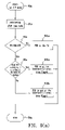
- FIG. 8( c ) is a flowchart of another method for determining the current position of a pick-up head in accordance with the present invention.
- An optical storage device can obtain the signals or information of the linear velocity of its pick-up head whenever the pick-up head is at a track locking state and thus confirmation of steady rotation is unnecessary; if this is the case, the acquired real-time linear velocity is divided by the immediate angular velocity to directly calculate the radial ratio of the current position of the pick-up head without any necessity of determining the current rotation mode of the optical storage device.
- Step 82 c the pick-up head retrieves the ATIP time code. Then, Step 82 c involves confirming whether the figure MM, which stands for minute in the timing code, ranges between the 95th minute and the 99th minute.
- the present embodiment is about the problem of overlapped time codes commonly seen in high capacity (HC) optical disks, such as HC-CDR.
- the present invention is not limited to the scope of overlapped time illustrated in the present embodiment, wherein the lower limit of overlapped time may be greater or less than the 95th minute.
- the pick-up head is located at a program area, as shown in Step 821 c ; otherwise, it is necessary to check and see whether the linear velocity to angular velocity ratio is greater than a predetermined threshold value, as shown in Step 83 c . If the aforesaid condition is satisfied, it means that the pick-up head is located at the outside tracks of the optical disk and it is necessary to set an area flag to 1, as shown in Step 832 c . If, however, the linear velocity is less than a predetermined threshold value, it means that the pick-up head is located at a lead-in area disposed in the innermost tracks and it is necessary to set the area flag to 0, as shown in Step 831 c.
- an optical storage device can obtain the linear velocity signals of its pick-up head whenever the pick-up head is at a track locking state and thus confirmation of steady rotation is unnecessary; if this is the case, the determination unit 97 calculates the current linear velocity to angular velocity ratio and determines whether the ratio is greater than a corresponding predetermined threshold value, and then it further outputs the position area flag as a basis for any tracking actions carried out by the system.
- Conditions used by the position condition determination unit 97 of the pick-up head may also be set in accordance with external configuration conditions 99 ; This predetermined threshold value may be changed according to the storage formats or specifications of optical disks in order to determine the current position of the pick-up head.
- the present invention has the following advantages, compared to the conventional art:
Landscapes
- Optical Recording Or Reproduction (AREA)
Abstract
Description
-
- where r2, V1 and V2 are known, thus r1 is obtained and then used for determining the absolute position of the whereabouts of the pick-up head.
Claims (19)
Applications Claiming Priority (2)
| Application Number | Priority Date | Filing Date | Title |
|---|---|---|---|
| TW093111125A TWI305640B (en) | 2004-04-21 | 2004-04-21 | Method for determining the position of a pick-up head and apparatus therefor |
| TW093111125 | 2004-04-21 |
Publications (2)
| Publication Number | Publication Date |
|---|---|
| US20050237878A1 US20050237878A1 (en) | 2005-10-27 |
| US7289397B2 true US7289397B2 (en) | 2007-10-30 |
Family
ID=35136259
Family Applications (1)
| Application Number | Title | Priority Date | Filing Date |
|---|---|---|---|
| US10/906,982 Expired - Fee Related US7289397B2 (en) | 2004-04-21 | 2005-03-15 | Method and apparatus for determining position of optical pick-up head |
Country Status (2)
| Country | Link |
|---|---|
| US (1) | US7289397B2 (en) |
| TW (1) | TWI305640B (en) |
Citations (4)
| Publication number | Priority date | Publication date | Assignee | Title |
|---|---|---|---|---|
| US5790488A (en) * | 1993-12-15 | 1998-08-04 | Nippon Columbia Co., Ltd. | Optical disk having both constant linear and constant angular velocity recording regions and optical disk recording system |
| US6111830A (en) * | 1998-02-13 | 2000-08-29 | International Business Machines Corporation | System for creating, reading and writing on rotatable information storage media, an apparatus for determining linear and/or angular velocity |
| TW544669B (en) | 2000-11-30 | 2003-08-01 | Via Tech Inc | Searching method and device for position of optical pick-up head |
| US6914862B2 (en) * | 2001-02-16 | 2005-07-05 | Mediatek Inc. | Device and method for calibrating linear velocity and track pitch for optical disc drive |
-
2004
- 2004-04-21 TW TW093111125A patent/TWI305640B/en not_active IP Right Cessation
-
2005
- 2005-03-15 US US10/906,982 patent/US7289397B2/en not_active Expired - Fee Related
Patent Citations (4)
| Publication number | Priority date | Publication date | Assignee | Title |
|---|---|---|---|---|
| US5790488A (en) * | 1993-12-15 | 1998-08-04 | Nippon Columbia Co., Ltd. | Optical disk having both constant linear and constant angular velocity recording regions and optical disk recording system |
| US6111830A (en) * | 1998-02-13 | 2000-08-29 | International Business Machines Corporation | System for creating, reading and writing on rotatable information storage media, an apparatus for determining linear and/or angular velocity |
| TW544669B (en) | 2000-11-30 | 2003-08-01 | Via Tech Inc | Searching method and device for position of optical pick-up head |
| US6914862B2 (en) * | 2001-02-16 | 2005-07-05 | Mediatek Inc. | Device and method for calibrating linear velocity and track pitch for optical disc drive |
Also Published As
| Publication number | Publication date |
|---|---|
| TWI305640B (en) | 2009-01-21 |
| TW200535790A (en) | 2005-11-01 |
| US20050237878A1 (en) | 2005-10-27 |
Similar Documents
| Publication | Publication Date | Title |
|---|---|---|
| EP1840899B1 (en) | Recording medium, recording apparatus, and reading apparatus | |
| JP4277452B2 (en) | Recording device, playback device | |
| JP4816749B2 (en) | Recording device | |
| JP2001312861A (en) | Recording medium, recording device, playback device | |
| US7289397B2 (en) | Method and apparatus for determining position of optical pick-up head | |
| JP2002025199A (en) | Recording device, recording medium, reproducing device, method of determining recording medium | |
| US7457208B2 (en) | Method and apparatus for determining position of optical pick-up head | |
| US7304927B2 (en) | Enhanced testing region access for optical disks | |
| JP2002222586A (en) | Recording device | |
| CN100444257C (en) | Method and device for judging the position of optical read-write head | |
| JP2001243722A (en) | Disk recording medium and disk drive device | |
| CN100401381C (en) | Method and device for judging position of optical read-write head | |
| JP2004348894A (en) | Optical disk unit and method for controlling optical disk unit | |
| JP2002216346A (en) | Disk drive device, address acquisition method | |
| JP2002298370A (en) | Playback device and playback method | |
| JP2001236770A (en) | Disk recording medium, recording device, reproducing device | |
| JP2002056607A (en) | Recording device, playback device, recording medium |
Legal Events
| Date | Code | Title | Description |
|---|---|---|---|
| AS | Assignment |
Owner name: MEDIATEK INC., TAIWAN Free format text: ASSIGNMENT OF ASSIGNORS INTEREST;ASSIGNOR:LIU, TUN-HSING;REEL/FRAME:015776/0296 Effective date: 20050204 |
|
| STCF | Information on status: patent grant |
Free format text: PATENTED CASE |
|
| FPAY | Fee payment |
Year of fee payment: 4 |
|
| FPAY | Fee payment |
Year of fee payment: 8 |
|
| FEPP | Fee payment procedure |
Free format text: MAINTENANCE FEE REMINDER MAILED (ORIGINAL EVENT CODE: REM.); ENTITY STATUS OF PATENT OWNER: LARGE ENTITY |
|
| LAPS | Lapse for failure to pay maintenance fees |
Free format text: PATENT EXPIRED FOR FAILURE TO PAY MAINTENANCE FEES (ORIGINAL EVENT CODE: EXP.); ENTITY STATUS OF PATENT OWNER: LARGE ENTITY |
|
| STCH | Information on status: patent discontinuation |
Free format text: PATENT EXPIRED DUE TO NONPAYMENT OF MAINTENANCE FEES UNDER 37 CFR 1.362 |
|
| FP | Lapsed due to failure to pay maintenance fee |
Effective date: 20191030 |