US7281433B2 - Probe for three-dimensional measurements - Google Patents
Probe for three-dimensional measurements Download PDFInfo
- Publication number
- US7281433B2 US7281433B2 US11/178,706 US17870605A US7281433B2 US 7281433 B2 US7281433 B2 US 7281433B2 US 17870605 A US17870605 A US 17870605A US 7281433 B2 US7281433 B2 US 7281433B2
- Authority
- US
- United States
- Prior art keywords
- mobile element
- probe
- actuator
- mobile
- axis
- Prior art date
- Legal status (The legal status is an assumption and is not a legal conclusion. Google has not performed a legal analysis and makes no representation as to the accuracy of the status listed.)
- Active, expires
Links
Images


Classifications
-
- G—PHYSICS
- G01—MEASURING; TESTING
- G01B—MEASURING LENGTH, THICKNESS OR SIMILAR LINEAR DIMENSIONS; MEASURING ANGLES; MEASURING AREAS; MEASURING IRREGULARITIES OF SURFACES OR CONTOURS
- G01B5/00—Measuring arrangements characterised by the use of mechanical techniques
- G01B5/004—Measuring arrangements characterised by the use of mechanical techniques for measuring coordinates of points
- G01B5/008—Measuring arrangements characterised by the use of mechanical techniques for measuring coordinates of points using coordinate measuring machines
- G01B5/012—Contact-making feeler heads therefor
-
- G—PHYSICS
- G01—MEASURING; TESTING
- G01B—MEASURING LENGTH, THICKNESS OR SIMILAR LINEAR DIMENSIONS; MEASURING ANGLES; MEASURING AREAS; MEASURING IRREGULARITIES OF SURFACES OR CONTOURS
- G01B21/00—Measuring arrangements or details thereof, where the measuring technique is not covered by the other groups of this subclass, unspecified or not relevant
- G01B21/02—Measuring arrangements or details thereof, where the measuring technique is not covered by the other groups of this subclass, unspecified or not relevant for measuring length, width, or thickness
- G01B21/04—Measuring arrangements or details thereof, where the measuring technique is not covered by the other groups of this subclass, unspecified or not relevant for measuring length, width, or thickness by measuring coordinates of points
- G01B21/045—Correction of measurements
Definitions
- the present invention concerns a touch probe capable of being oriented in space along a multiplicity of directions.
- This probe is designed to be used more particularly, but not exclusively, in a manual or automatic measuring machine or in a machine tool such as for example a milling machine, for the three-dimensional measuring of a machined part or during machining.
- Touch probes are measuring elements used widely, but not uniquely, on production lines of mechanical parts, for example for accurately checking dimensions or surfaces of mechanical parts. Touch probes are also used for three-dimensional measuring of pieces of complex shape, in order to reproduce or model them.
- Touch probes generally comprise a fixed part, designed to be fastened onto a measuring machine or on a machine tool, and a mobile feeler, comprising a sphere at the end of an elongated rod and designed to be brought into contact with the piece to be measured.
- touch probes are fastened on the mobile arm of a machine whose position can be determined accurately by means of a manual or automatic measuring system, such as for example position encoders placed on the axes of the machine.
- the mobile arm is moved in space until the probe's measuring feeler comes into contact with the piece or the surface to be measured.
- a deflective force is thus applied on the feeler, moving it away from its initial resting position.
- a sensor reacts to the slightest displacement of the feeler, generating an electric signal that is sent either to the user, in the form of a light signal, or to the machine's control software which thus determines, on the basis of the data of the measuring system, the coordinates of the contact point within a given reference frame.
- the prior art uses electromechanical or optical sensors or movement sensors based on different principles, for example sensors comprising constraint gauges.
- connection between the feeler and the probe's fixed part is usually realized according to the principle of the Boys connection, i.e. for example by three cylindrical pins resting on six spheres so as to define six contact points between the fixed organ and the feeler.
- Two- and one-dimensional probes are however also known.
- probes are known that allow the contact feeler to be oriented in a plurality of directions in space. Generally, two independent rotation axes are required to cover all the possible orientations. A probe of this type is described in European patent application EP0392660.
- the rotation axes are preferably indexed, meaning that a sufficiently large but finite number of predetermined and accurately reproducible resting positions are provided. This arrangement avoids the measuring machine having to be re-calibrated after each change in orientation of the feeler.
- the axes allowing the above prior art probe to be oriented are locked in one of the provided indexed positions.
- the operator must manually unlock the axes by actuating a wheel or a lever provided to this effect, orient the probe as required, and lock again the axes by repositioning the wheel or lever in the initial locking position.
- One aim of the present invention is to propose a touch probe capable of being oriented in a multiplicity of indexed directions and that can be positioned reliably without risk of positioning errors.
- Another aim of the present invention is to propose a touch probe without the limitations of the prior art.
- Another aim of the present invention is to propose a touch probe capable of being oriented in a multiplicity of indexed direction and that can be operated more easily than the prior art probes.
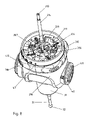
- FIG. 1 shows an embodiment of a touch probe according to the invention
- FIG. 2 shows a cross section of the touch probe of the invention represented in FIG. 1 ;
- FIGS. 3 and 4 show the indexing and demultiplying mechanism used to disengage a second horizontal axis of the probe of FIG. 1 ;
- FIG. 5 represents a fixed part of the probe of FIG. 1 ;
- FIG. 6 illustrates a mobile part around a first vertical axis of the probe of FIG. 1 ;
- FIG. 7 shows an indexing and demultiplying mechanism used to disengage a first vertical axis of the probe of FIG. 1 ;
- FIG. 8 represents the probe of FIG. 1 at partial stage of its assembly
- FIG. 9 shows a cross section of the probe of FIG. 1 in a locked position
- FIG. 10 shows a cross section of the probe of FIG. 1 in a disengaged position of a first vertical rotation axis.
- the first embodiment of the invention represented in FIG. 1 is a touch probe 20 comprising a fixed part 250 , represented in detail in FIG. 5 , designed to be fastened to the mobile arm of a measuring machine by the threaded rod 251 or by other known fastening means.
- the fixed part 250 has on its lower face 24 spheres 256 , regularly spaced along a circumference and partially protruding downwards.
- the spheres 256 define 24 indexed positions spaced by 15 degrees for a first rotation axis of the probe, as will be explained further below.
- the inventive probe can be used with any orientation in space.
- the term “vertical” will be used hereinafter to designate the first rotation axis of the probe 211 , corresponding to a geometric axis of the probe, and the term “horizontal” for the second axis 212 , orthogonal thereto. These terms refer to the conventional orientation used in the figures, and notably in FIG. 2 on which the two axes 211 and 212 are represented.
- first and second the two axes and various elements of the probe will also be referred to hereinafter with the terms “first” and “second”. These terms must however not be understood in the sense that the invention is restricted to a device with two axes, as the invention also comprises probes with one, three or any number of rotation axes.
- the terms “first” and “second” also do not imply any kind or order or subordination relation between the elements, and are used here merely as indicators for distinguishing the elements of the inventive device.
- the mobile element 210 bears on its upper face three cylindrical pins 217 .
- the helical spring 235 visible in FIG. 9 , pulls the mobile element 210 against the fixed element 250 through the rod 219 .
- each of the pins 217 rests on two of the spheres 256 , the six resulting contact points determining the relative position of the elements 250 and 210 in an accurate and reproducible fashion.
- the mobile element 20 can take up 24 indexed positions, spaced by 15 degrees from one another, around the first rotation axis 211 , which corresponds to the probe's geometric axis.
- the same result could have been achieved by other equivalent arrangements, for example by placing the spheres on the mobile element and the pins on the fixed element, or by replacing the spherical or cylindrical surfaces of the pins or of the spheres by inclined planes, or also by using six cylindrical pins having each only a single contact point with one of the spheres.
- the disengaging mechanism 300 makes it possible to allow the mobile element 210 to rotate around the axis 211 .
- the transmission 300 includes four levers 306 , driven by the four push buttons 310 , and by the four rollers 307 , referenced in FIG. 7 .
- the rollers 307 push against the back-up ring 314 and, through the ball bearing 313 , axially move the fixed element 250 away from the mobile element 210 .
- the spheres 256 referenced in FIGS. 9 and 10 , clear the pins 217 without touching them, and the rotation around the axis 211 is possible.
- the resting force of the pins 217 on the spheres 256 must be sufficiently high to prevent any accidental movement of the mobile part 210 during measuring.
- the indexing spring 235 is dimensioned for a total resting force of approximately 30 N, for example, i.e. about 10 N for each of the six contact points, since the pressure is exerted at 60 degrees relatively to the axis.
- buttons 310 It would be difficult to apply a force of 30 N directly on the buttons 310 .
- the dimensions of the levers 306 and the position of the pivots 304 are chosen to give a sufficient demultiplication ratio between the radial force exerted on the buttons 310 and the axial force which opposes the elasticity of the spring 235 .
- a reduction ratio of 1:2 implies an actuating force at the buttons 310 of about 15N, i.e. approximately 1.5 Kgf, which the user can exert without great difficulty.
- the travel range of the buttons 310 remains contained, with this reduction ratio, to several millimeters.
- numeric values given here above must be interpreted as examples that are particularly suited to the presented embodiment. It would be possible to chose different values according to circumstances, for example according to the mass and the dimensions of the probe.
- buttons 310 While the buttons 310 are pushed along the radial direction, the operator can make the mobile element 210 turn around the axis 211 by actuating the same buttons in tangential direction. This operation is very intuitive and can easily be performed with two fingers of one hand. In this condition, the distance apart between the spheres 256 and the pins 217 is sufficient to avoid any contact or friction of the indexing surfaces, thus maintaining the positioning accuracy in indexed position. It is thus not necessary to release the buttons 310 to pass from the unlocking to the probe's rotation and then to locking of the probe again.
- the reduction ratio and the friction coefficients of the used materials will be chosen so that the transmission 300 is reversible, so that the mobile element 210 spontaneously returns to indexed position once the pressure on the buttons 310 is released, thus avoiding an accidental use in the disengaged position.
- the force moving apart the fixed element 250 and the mobile element 210 generated by the transmission 300 is generally aligned and opposed to the force exerted by the indexing spring 235 and transmitted by the rods 214 and 219 , so as to ensure a frictionless rotation in the disengaged position.
- a bearing 313 for example a thrust ball bearing, is interposed between the fixed element 250 and the mobile element 210 , so as to reduce friction during rotation around the first axis 211 .
- Another type of bearing for example ball or roller bearing, could also be used instead of a thrust ball bearing.
- the force of the indexing spring is applied by the rods 214 and 219 exactly at the center of gravity of said six contact points and corresponding to the rotation axis 211 , to ensure optimum resting.
- the indexing spring 235 is preferably lodged inside the support rod 251 in order to be able to use a very long spring, thus of weak rigidity, which ensures a constant traction force along the entire travel range.
- the indexing force can easily be adjusted by using the screw 218 at the end of the support rod, or by another equivalent means.
- the screw 218 is easily accessible from outside without disassembling the probe, by simply opening the lid 252 for example.
- the first mobile element 210 is connected to a second mobile element 220 capable of turning around the rotation axis 212 , perpendicular to the first rotation axis 211 , to which a trigger 30 of known type is fastened as can be seen in FIG. 2 .
- the second mobile element 220 is pushed against the first mobile element 210 , in the axial direction defined by the rotation axis 212 , by the compression spring 225 .
- a crown of spheres 226 is made on a vertical face of the mobile element 220 and interacts with three cylindrical pins (not represented in the figure) placed on the face adjacent to the first mobile element 210 to define a predetermined number of exactly reproducible indexing positions, in analog fashion to that explained here above for the rotation of the first mobile element 210 .
- six cylindrical pins having only a single contact point can be used.
- the disengaging and rotation system 400 of the second mobile element 220 is represented in FIGS. 3 and 4 .
- the disengaging is effected by applying pressure on the two buttons 411 and 410 .
- the axial force applied on the button 410 that can slide axially around the part 470 is transmitted by the two levers 430 and 450 and the horizontal arm 440 , is multiplied and applied to the spring 225 by the pin 461 and the rod 460 , in order to compress it, which cancels the contact force between 220 and 210 .
- the dimensions of the arms of the levers 430 , 450 are chosen so as to achieve an operating force reduction ratio of 1:2, for example, as for the first mobile element 210 .
- a second spring 475 interposed between the button 410 and the part 470 , axially pushes to the right on FIG. 2 the second mobile element 220 while allowing it to rotate.
- the button 410 When the button 410 is pushed, the second mobile element 220 is displaced to the right of FIG. 2 , so that the pins and the indexing spheres 226 no longer touch, and the second mobile element 220 can turn around the axis 212 .
- the rotation is effected by the operator through the button 410 that is united angularly to the part 470 by a pin, not visible in the figures.
- the button 411 opposed to the button 410 , has the two-fold function of offering a resting surface to the finger to exert a force opposed to that applied on the button 410 , and of facilitating the rotation of the element 220 with two fingers.
- the button 411 is in fact united angularly to the element 220 and driven in rotation with it. Use of two forces essentially opposed to one another makes it possible to avoid efforts being transmitted to the probe's support and making the whole probe move.
- the action of the button 410 on the second mobile element 220 through the rod 460 is substantially aligned and opposed to the force exerted by the spring 225 , which ensures rectilinear movements without jamming.
- the electric signal generated by the trigger 30 is sent either to the user, in the form of a light signal emitted by the light diode 50 ( FIG. 1 ) or to the machine's control software which thus determines by means of the measuring system's data the coordinates of the contact point within a given referential frame.
- the second mobile element 220 can take up, in this embodiment, 7 indexed positions spaced by 15 degrees to one another, for a total angle of 90 degrees. This angle, in combination with the possible rotation of 360 degrees for the first rotation element 210 , makes it possible to orient the trigger 30 in a number of directions uniformly distributed in a half-space. It would however be possible to make the inventive device with a generic number of indexed positions and any distances between them.
- buttons 310 are surrounded by an annular rubber or elastomer protective membrane 330 whose function it is to protect the inner mechanism from dirt and dust, but also to prevent heat from the operator's hands to be transmitted to the internal indexing mechanism, which would have detrimental consequences on the indexing accuracy.
- the buttons 410 and 411 serving for the rotation and disengagement of the second axis 212 , are also preferably made of a synthetic material with good heat insulation properties.
- a window 41 is provided on the support element 250 allowing the rotation angle relative to the first axis 211 to be read on a scale 47 engraved or printed on the first mobile element 210 , as can be seen in FIGS. 1 and 8 .
- the rotation angle relative to the second axis 212 can be read on the two windows 40 cut out in the external crown of the button 411 . At least two windows are necessary in this case to allow optimum visibility in all the probe's possible orientations.
- the trigger 30 reacts to the slightest contact with the surface of the piece to be measured by generating an electric pulse.
- the pulse is transmitted, through an electronic processing circuit and a connector (not represented) for connection with the control device of the measuring machine, and to the light display 50 .
- the display comprises in this embodiment a light diode, but could alternatively comprise other known light emitters, such as for example sheet or wire electroluminescent elements.
- the light diode is surmounted by an optical light diffuser, allowing the light emitted to be seen in a wider range of observation angles.
- the display 50 is replaced by several displays, placed at different places of the probe, so that at least one display is visible from each possible observation angle.
- the display 50 comprises one or several light conductors to emit the light produced by one or several light sources from different places of the probe's surface, so that the light indication is visible from each possible observation angle.
- the invention also includes an embodiment in which the rotation and the disengagement of the axes are actuated by automatic actuators, for example electric motors and/or solenoids.
- automatic actuators for example electric motors and/or solenoids.
Landscapes
- Physics & Mathematics (AREA)
- General Physics & Mathematics (AREA)
- A Measuring Device Byusing Mechanical Method (AREA)
- Length Measuring Devices With Unspecified Measuring Means (AREA)
Applications Claiming Priority (2)
| Application Number | Priority Date | Filing Date | Title |
|---|---|---|---|
| EP2004EP-103304 | 2004-07-12 | ||
| EP04103304A EP1617171B1 (de) | 2004-07-12 | 2004-07-12 | Taster zur Messung in drei Dimensionen |
Publications (2)
| Publication Number | Publication Date |
|---|---|
| US20060005633A1 US20060005633A1 (en) | 2006-01-12 |
| US7281433B2 true US7281433B2 (en) | 2007-10-16 |
Family
ID=34929316
Family Applications (1)
| Application Number | Title | Priority Date | Filing Date |
|---|---|---|---|
| US11/178,706 Active 2025-12-25 US7281433B2 (en) | 2004-07-12 | 2005-07-11 | Probe for three-dimensional measurements |
Country Status (6)
| Country | Link |
|---|---|
| US (1) | US7281433B2 (de) |
| EP (1) | EP1617171B1 (de) |
| JP (1) | JP3944220B2 (de) |
| CN (1) | CN100360892C (de) |
| DE (1) | DE602004010639T2 (de) |
| HK (1) | HK1084723A1 (de) |
Cited By (5)
| Publication number | Priority date | Publication date | Assignee | Title |
|---|---|---|---|---|
| US20140167745A1 (en) * | 2011-07-08 | 2014-06-19 | Carl Zeiss Industrielle Messtechnik Gmbh | Correcting and/or preventing errors during the measurement of coordinates of a workpiece |
| US8921788B1 (en) | 2013-06-28 | 2014-12-30 | Unimetrik, S.A. | Laser sensor with integrated rotating mechanism |
| US9810529B2 (en) | 2015-03-05 | 2017-11-07 | Mitotoyo Corporation | Measuring probe for measuring a three-dimensional shape of an object to be measured |
| US10422628B2 (en) | 2015-03-05 | 2019-09-24 | Mitutoyo Corporation | Measuring probe |
| US11105605B2 (en) * | 2018-02-18 | 2021-08-31 | The L.S. Starrett Company | Metrology device with automated compensation and/or alert for orientation errors |
Families Citing this family (8)
| Publication number | Priority date | Publication date | Assignee | Title |
|---|---|---|---|---|
| JP2012519563A (ja) * | 2009-03-09 | 2012-08-30 | コーニンクレッカ フィリップス エレクトロニクス エヌ ヴィ | 対象にエネルギーを当てるためのカテーテル、装置、方法、及び、コンピュータプログラム |
| JP5136940B2 (ja) * | 2009-06-05 | 2013-02-06 | 公益財団法人北九州産業学術推進機構 | 三次元測定装置 |
| JP5336279B2 (ja) * | 2009-07-08 | 2013-11-06 | 株式会社ミツトヨ | 表面性状測定装置および真円度測定装置 |
| WO2013130185A1 (en) * | 2012-02-27 | 2013-09-06 | United Technologies Corporation | Machine tool - based, optical coordinate measuring machine calibration device |
| EP2657642A1 (de) | 2012-04-24 | 2013-10-30 | Hexagon Technology Center GmbH | Sensorelement für eine Messmaschine, insbesondere eine Koordinatenmessmaschine |
| JP6049785B2 (ja) * | 2015-03-05 | 2016-12-21 | 株式会社ミツトヨ | 測定プローブ |
| CN105436993B (zh) * | 2015-12-31 | 2017-10-03 | 山东省计算中心(国家超级计算济南中心) | 工件感知器和感知系统 |
| JP6341962B2 (ja) * | 2016-08-26 | 2018-06-13 | 株式会社ミツトヨ | 三次元測定装置及び座標補正方法 |
Citations (9)
| Publication number | Priority date | Publication date | Assignee | Title |
|---|---|---|---|---|
| EP0392660A2 (de) | 1989-04-14 | 1990-10-17 | Renishaw plc | Tastkopf |
| US5084981A (en) * | 1989-04-14 | 1992-02-04 | Renishaw Plc | Probe head |
| US20010025427A1 (en) | 2000-02-15 | 2001-10-04 | Werner Lotze | Articulated device for the probe head of a coordinate measuring apparatus |
| US20030101609A1 (en) * | 2001-11-30 | 2003-06-05 | Pascal Jordil | Trigger probe and method for assembling a trigger probe |
| US6634114B2 (en) * | 2000-04-12 | 2003-10-21 | Bidwell Corporation | Gage set for measuring inside and outside diameters of ring shaped parts |
| US6854195B2 (en) * | 2003-01-29 | 2005-02-15 | Tesa Sa | Adjustable probe |
| US6907673B2 (en) * | 2003-01-29 | 2005-06-21 | Tesa Sa | Adjustable probe |
| US6938353B2 (en) * | 2003-01-29 | 2005-09-06 | Tesa Sa | Adjustable probe |
| US7036239B2 (en) * | 2003-01-29 | 2006-05-02 | Tesa Sa | Adjustable probe |
Family Cites Families (1)
| Publication number | Priority date | Publication date | Assignee | Title |
|---|---|---|---|---|
| DE3740070A1 (de) * | 1987-11-26 | 1989-06-08 | Zeiss Carl Fa | Dreh-schwenk-einrichtung fuer tastkoepfe von koordinatenmessgeraeten |
-
2004
- 2004-07-12 EP EP04103304A patent/EP1617171B1/de not_active Expired - Lifetime
- 2004-07-12 DE DE602004010639T patent/DE602004010639T2/de not_active Expired - Lifetime
-
2005
- 2005-07-08 JP JP2005199892A patent/JP3944220B2/ja not_active Expired - Fee Related
- 2005-07-11 CN CNB2005100835806A patent/CN100360892C/zh active Active
- 2005-07-11 US US11/178,706 patent/US7281433B2/en active Active
-
2006
- 2006-04-20 HK HK06104740A patent/HK1084723A1/xx not_active IP Right Cessation
Patent Citations (11)
| Publication number | Priority date | Publication date | Assignee | Title |
|---|---|---|---|---|
| EP0392660A2 (de) | 1989-04-14 | 1990-10-17 | Renishaw plc | Tastkopf |
| US5084981A (en) * | 1989-04-14 | 1992-02-04 | Renishaw Plc | Probe head |
| US5088337A (en) * | 1989-04-14 | 1992-02-18 | Renishaw Plc | Probe head |
| US20010025427A1 (en) | 2000-02-15 | 2001-10-04 | Werner Lotze | Articulated device for the probe head of a coordinate measuring apparatus |
| US6634114B2 (en) * | 2000-04-12 | 2003-10-21 | Bidwell Corporation | Gage set for measuring inside and outside diameters of ring shaped parts |
| US20030101609A1 (en) * | 2001-11-30 | 2003-06-05 | Pascal Jordil | Trigger probe and method for assembling a trigger probe |
| US6760977B2 (en) * | 2001-11-30 | 2004-07-13 | Tesa Sa | Trigger probe and method for assembling a trigger probe |
| US6854195B2 (en) * | 2003-01-29 | 2005-02-15 | Tesa Sa | Adjustable probe |
| US6907673B2 (en) * | 2003-01-29 | 2005-06-21 | Tesa Sa | Adjustable probe |
| US6938353B2 (en) * | 2003-01-29 | 2005-09-06 | Tesa Sa | Adjustable probe |
| US7036239B2 (en) * | 2003-01-29 | 2006-05-02 | Tesa Sa | Adjustable probe |
Cited By (8)
| Publication number | Priority date | Publication date | Assignee | Title |
|---|---|---|---|---|
| US20140167745A1 (en) * | 2011-07-08 | 2014-06-19 | Carl Zeiss Industrielle Messtechnik Gmbh | Correcting and/or preventing errors during the measurement of coordinates of a workpiece |
| US9671257B2 (en) * | 2011-07-08 | 2017-06-06 | Carl Zeiss Industrielle Messtechnik Gmbh | Correcting and/or preventing errors during the measurement of coordinates of a workpiece |
| US10429178B2 (en) * | 2011-07-08 | 2019-10-01 | Carl Zeiss Industrielle Messtechnik Gmbh | Correcting and/or preventing errors during the measurement of coordinates of a work piece |
| US8921788B1 (en) | 2013-06-28 | 2014-12-30 | Unimetrik, S.A. | Laser sensor with integrated rotating mechanism |
| WO2014207266A1 (es) | 2013-06-28 | 2014-12-31 | Unimetrik, S.A. | Sensor láser con mecanismo de giro integrado |
| US9810529B2 (en) | 2015-03-05 | 2017-11-07 | Mitotoyo Corporation | Measuring probe for measuring a three-dimensional shape of an object to be measured |
| US10422628B2 (en) | 2015-03-05 | 2019-09-24 | Mitutoyo Corporation | Measuring probe |
| US11105605B2 (en) * | 2018-02-18 | 2021-08-31 | The L.S. Starrett Company | Metrology device with automated compensation and/or alert for orientation errors |
Also Published As
| Publication number | Publication date |
|---|---|
| DE602004010639T2 (de) | 2008-12-04 |
| EP1617171B1 (de) | 2007-12-12 |
| JP3944220B2 (ja) | 2007-07-11 |
| JP2006030186A (ja) | 2006-02-02 |
| CN1721812A (zh) | 2006-01-18 |
| EP1617171A1 (de) | 2006-01-18 |
| CN100360892C (zh) | 2008-01-09 |
| HK1084723A1 (en) | 2006-08-04 |
| DE602004010639D1 (de) | 2008-01-24 |
| US20060005633A1 (en) | 2006-01-12 |
Similar Documents
| Publication | Publication Date | Title |
|---|---|---|
| US7281433B2 (en) | Probe for three-dimensional measurements | |
| US6938353B2 (en) | Adjustable probe | |
| US7213344B2 (en) | Motorized orientable measuring head | |
| US7036239B2 (en) | Adjustable probe | |
| US8763267B2 (en) | Locking counterbalance for a CMM | |
| US6854195B2 (en) | Adjustable probe | |
| US5088337A (en) | Probe head | |
| JPS62177426A (ja) | 力及びトルク変換装置 | |
| US7263780B2 (en) | Motorized orientable measuring head | |
| US20110258868A1 (en) | Measuring system | |
| US6907673B2 (en) | Adjustable probe | |
| US7213345B2 (en) | Motorized orientable measuring head | |
| CN108712943A (zh) | 校准装置和方法 | |
| JP2024507198A (ja) | 多関節ヘッド | |
| TW202140194A (zh) | 校正裝置及方法 |
Legal Events
| Date | Code | Title | Description |
|---|---|---|---|
| AS | Assignment |
Owner name: TESA SA, SWITZERLAND Free format text: ASSIGNMENT OF ASSIGNORS INTEREST;ASSIGNORS:JORDIL, PASCAL;ROUGE, CLAUDE;WUNDERLIN, LEONARD;AND OTHERS;REEL/FRAME:016776/0699;SIGNING DATES FROM 20050425 TO 20050502 |
|
| FEPP | Fee payment procedure |
Free format text: PAYOR NUMBER ASSIGNED (ORIGINAL EVENT CODE: ASPN); ENTITY STATUS OF PATENT OWNER: LARGE ENTITY |
|
| STCF | Information on status: patent grant |
Free format text: PATENTED CASE |
|
| FEPP | Fee payment procedure |
Free format text: PAYER NUMBER DE-ASSIGNED (ORIGINAL EVENT CODE: RMPN); ENTITY STATUS OF PATENT OWNER: LARGE ENTITY Free format text: PAYOR NUMBER ASSIGNED (ORIGINAL EVENT CODE: ASPN); ENTITY STATUS OF PATENT OWNER: LARGE ENTITY |
|
| FPAY | Fee payment |
Year of fee payment: 4 |
|
| FPAY | Fee payment |
Year of fee payment: 8 |
|
| MAFP | Maintenance fee payment |
Free format text: PAYMENT OF MAINTENANCE FEE, 12TH YEAR, LARGE ENTITY (ORIGINAL EVENT CODE: M1553); ENTITY STATUS OF PATENT OWNER: LARGE ENTITY Year of fee payment: 12 |