US7277407B2 - Apparatus and method for controlling transmit antenna array for physical downlink shared channel in a mobile communication system - Google Patents
Apparatus and method for controlling transmit antenna array for physical downlink shared channel in a mobile communication system Download PDFInfo
- Publication number
- US7277407B2 US7277407B2 US09/975,419 US97541901A US7277407B2 US 7277407 B2 US7277407 B2 US 7277407B2 US 97541901 A US97541901 A US 97541901A US 7277407 B2 US7277407 B2 US 7277407B2
- Authority
- US
- United States
- Prior art keywords
- node
- signal
- pdsch
- dpch
- weight
- Prior art date
- Legal status (The legal status is an assumption and is not a legal conclusion. Google has not performed a legal analysis and makes no representation as to the accuracy of the status listed.)
- Expired - Fee Related, expires
Links
Images


Classifications
-
- H—ELECTRICITY
- H04—ELECTRIC COMMUNICATION TECHNIQUE
- H04W—WIRELESS COMMUNICATION NETWORKS
- H04W16/00—Network planning, e.g. coverage or traffic planning tools; Network deployment, e.g. resource partitioning or cells structures
- H04W16/24—Cell structures
- H04W16/28—Cell structures using beam steering
-
- H—ELECTRICITY
- H04—ELECTRIC COMMUNICATION TECHNIQUE
- H04W—WIRELESS COMMUNICATION NETWORKS
- H04W52/00—Power management, e.g. TPC [Transmission Power Control], power saving or power classes
- H04W52/04—TPC
- H04W52/38—TPC being performed in particular situations
- H04W52/40—TPC being performed in particular situations during macro-diversity or soft handoff
-
- H—ELECTRICITY
- H04—ELECTRIC COMMUNICATION TECHNIQUE
- H04B—TRANSMISSION
- H04B7/00—Radio transmission systems, i.e. using radiation field
- H04B7/02—Diversity systems; Multi-antenna system, i.e. transmission or reception using multiple antennas
- H04B7/022—Site diversity; Macro-diversity
-
- H—ELECTRICITY
- H04—ELECTRIC COMMUNICATION TECHNIQUE
- H04B—TRANSMISSION
- H04B7/00—Radio transmission systems, i.e. using radiation field
- H04B7/02—Diversity systems; Multi-antenna system, i.e. transmission or reception using multiple antennas
- H04B7/04—Diversity systems; Multi-antenna system, i.e. transmission or reception using multiple antennas using two or more spaced independent antennas
- H04B7/06—Diversity systems; Multi-antenna system, i.e. transmission or reception using multiple antennas using two or more spaced independent antennas at the transmitting station
- H04B7/0613—Diversity systems; Multi-antenna system, i.e. transmission or reception using multiple antennas using two or more spaced independent antennas at the transmitting station using simultaneous transmission
- H04B7/0615—Diversity systems; Multi-antenna system, i.e. transmission or reception using multiple antennas using two or more spaced independent antennas at the transmitting station using simultaneous transmission of weighted versions of same signal
- H04B7/0619—Diversity systems; Multi-antenna system, i.e. transmission or reception using multiple antennas using two or more spaced independent antennas at the transmitting station using simultaneous transmission of weighted versions of same signal using feedback from receiving side
- H04B7/0621—Feedback content
- H04B7/0634—Antenna weights or vector/matrix coefficients
-
- H—ELECTRICITY
- H04—ELECTRIC COMMUNICATION TECHNIQUE
- H04B—TRANSMISSION
- H04B7/00—Radio transmission systems, i.e. using radiation field
- H04B7/02—Diversity systems; Multi-antenna system, i.e. transmission or reception using multiple antennas
- H04B7/04—Diversity systems; Multi-antenna system, i.e. transmission or reception using multiple antennas using two or more spaced independent antennas
- H04B7/06—Diversity systems; Multi-antenna system, i.e. transmission or reception using multiple antennas using two or more spaced independent antennas at the transmitting station
- H04B7/0686—Hybrid systems, i.e. switching and simultaneous transmission
- H04B7/0689—Hybrid systems, i.e. switching and simultaneous transmission using different transmission schemes, at least one of them being a diversity transmission scheme
-
- H—ELECTRICITY
- H04—ELECTRIC COMMUNICATION TECHNIQUE
- H04W—WIRELESS COMMUNICATION NETWORKS
- H04W36/00—Hand-off or reselection arrangements
- H04W36/16—Performing reselection for specific purposes
- H04W36/18—Performing reselection for specific purposes for allowing seamless reselection, e.g. soft reselection
-
- H—ELECTRICITY
- H04—ELECTRIC COMMUNICATION TECHNIQUE
- H04W—WIRELESS COMMUNICATION NETWORKS
- H04W48/00—Access restriction; Network selection; Access point selection
- H04W48/08—Access restriction or access information delivery, e.g. discovery data delivery
- H04W48/12—Access restriction or access information delivery, e.g. discovery data delivery using downlink control channel
-
- H—ELECTRICITY
- H04—ELECTRIC COMMUNICATION TECHNIQUE
- H04B—TRANSMISSION
- H04B7/00—Radio transmission systems, i.e. using radiation field
- H04B7/02—Diversity systems; Multi-antenna system, i.e. transmission or reception using multiple antennas
- H04B7/04—Diversity systems; Multi-antenna system, i.e. transmission or reception using multiple antennas using two or more spaced independent antennas
- H04B7/06—Diversity systems; Multi-antenna system, i.e. transmission or reception using multiple antennas using two or more spaced independent antennas at the transmitting station
- H04B7/0613—Diversity systems; Multi-antenna system, i.e. transmission or reception using multiple antennas using two or more spaced independent antennas at the transmitting station using simultaneous transmission
- H04B7/0667—Diversity systems; Multi-antenna system, i.e. transmission or reception using multiple antennas using two or more spaced independent antennas at the transmitting station using simultaneous transmission of delayed versions of same signal
- H04B7/0669—Diversity systems; Multi-antenna system, i.e. transmission or reception using multiple antennas using two or more spaced independent antennas at the transmitting station using simultaneous transmission of delayed versions of same signal using different channel coding between antennas
Definitions
- the present invention relates generally to a mobile communication system, and in particular, to an apparatus and method for controlling a transmit antenna array (TxAA) for a physical downlink shared channel (PDSCH) in a soft handover (SHO) region.
- TxAA transmit antenna array
- PDSCH physical downlink shared channel
- SHO soft handover
- a physical downlink shared channel (PDSCH) used in an asynchronous W-CDMA (Wideband Code Division Multiple Access) mobile communication system refers a channel shared by a plurality of UEs (User Equipments).
- the PDSCH is a channel assigned to transmit packet data or high-rate data to the UEs in a 10 ms radio frame unit, and is commonly used by a plurality of the UEs.
- the PDSCH can vary a data rate of transmission data in a frame unit, and can also perform weight adjustment on a transmit antenna array and power control in a slot unit, like a dedicated channel (DCH) established between a Node B and a UE in the W-CDMA system.
- DCH dedicated channel
- the radio frame a basic unit for transmitting signals in the W-CDMA system, has a length of 10 ms, and each radio frame is comprised of 15 slots.
- the PDSCH is a channel for transmitting user data only.
- a downlink dedicated physical channel (DL-DPCH) is assigned to the UE in association with the PDSCH.
- the DL-DPCH becomes a channel for power control on the PDSCH.
- the PDSCH can be continuously transmitted to one UE over a plurality of frames. Alternatively, the PDSCH can be transmitted to the UE over only one frame.
- the time to transmit the frames to a plurality of the UEs is determined by scheduling in an upper layer.
- FIG. 1A illustrates a structure of the PDSCH used in a mobile communication system
- FIG. 1B illustrates a structure of the DL-DPCH assigned to the UE in association with the PDSCH.
- a radio frame 101 of the PDSCH is 10 ms in length, and is comprised of 15 slots Slot#0–Slot#14.
- Each slot e.g., a slot Slot#i ( 103 )
- the SF has a value of 4 to 256, and transmission information data is spread according to the SF value. Only the user data is transmitted over the PDSCH.
- a radio frame 111 of the DL-DPCH is also comprised of 15 slots Slot# 0 –Slot# 14 , and each slot, as shown in FIG. 1B , is comprised of Data1 bits 112 , TPC (Transmit Power Control) bits 113 , TFCI (Transmit Format Combination Indicator) bits 114 , Data2 bits 115 , and Pilot bits 116 .
- Each slot of the DL-DPCH can have various structures according to the lengths of Data1, TPC, TFCI, Data2 and Pilot.
- the Data1 bits 112 and the Data2 bits 115 are transmitted over a downlink dedicated physical data channel (DL-DPDCH), and the DL-DPDCH transmits user data and signaling information from the upper layer.
- the TPC 113 , the TFCI 114 , and the Pilot 116 are transmitted over a downlink dedicated physical control channel (DL-DPCCH).
- the TPC 113 is a field for transmitting a command for controlling transmission power of uplink channels transmitted from the UE to the Node B;
- the TFCI 114 is a field for transmitting a codeword indicating that transport channels having different data rates are transmitted over the DL-DPCH;
- the Pilot 116 is a field for enabling the UE to measure transmission power of a downlink signal for power control on the received downlink signal.
- the “transport channel” refers to a channel serving to connect a physical channel for actually transmitting the data to the upper layer.
- the UE receiving the DL-DPCH 111 transmits, to the Node B, weight information acquired by measuring a common pilot channel (CPICH) received from the Node B. That is, upon receiving the CPICH transmitted from the Node B, the UE compensates for its phase difference thereby to detect a weight proper for the maximum receiving power level.
- the weight information created depending on the detected weight is transmitted to the Node B, and the Node B applies corresponding weights to respective antennas for the DL-DPCH transmitted to the UE, depending on the weight information of the DL-DPCH and/or PDSCH received from the UE, before transmission.
- CPICH common pilot channel
- FIG. 2 illustrates downlink and uplink signal flows for the case where the UE receiving the PDSCH is located in a soft handover (or handoff) region.
- FIG. 2 illustrates downlink and uplink signal flows for the case where a UE receiving a PDSCH is located in a soft handover region, wherein for simplicity, only two Node Bs are considered.
- a soft handover (SHO) process when a UE moves away from a current Node B1 in communication with the UE, and at the same time moves to an area where it can receive signals from an adjacent new Node B2, the UE receives the signals not only from the current Node B1 but also from the new Node B2. In this state, if a quality (or level) of the signal received from the Node B1 is less than a predetermined threshold, the UE releases the channel established to the Node B1, and then establishes a new channel to the Node B2 providing high-quality signals, thus performing the handover process. By doing so, it is possible to maintain a call without interruption.
- SHO soft handover
- a Node B1 201 which is currently communicated with a UE 211 , transmits a PDSCH and a DL-DPCH associated with the PDSCH to the UE 211 .
- a Node B2 203 transmits only the DL-DPCH to the UE 211 when the UE 211 moves to an SHO region between the Node B1 201 and the Node B2 203 .
- a set of all the Node Bs set to transmit signals to the UE 211 existing in the SHO region is called an “active set”.
- the Node B1 201 transmits both the DL-DPCH and the PDSCH to the UE 211 , and Node B2 203 is newly admitted to the active set and transmits only a DL-DPCH to the UE 211 .
- the UE 211 broadcasts the UL-DPCH to Node B1 201 and Node B2 203 indiscriminately.
- the UE 211 receives CPICHs from node B1 201 and node B2 203 together and measures the signal strengths of the CPICHs to select a primary node B among the Node Bs.
- the UE 211 transmits the temporary ID of a node B designated as a primary Node B in the feedback information (FBI) field of a UL_DCH.
- the FBI is 2 fields in length as shown.
- the S field consists of 0, 1 or 2 bits. If the S field consists of 0 bit, this implies that the SSDT is not used. If the SSDT is used, the FBI field transmits a codeword representing the temporary ID of a primary Node B.
- the D field consists of 0, 1, or 2 bits. If the D field consists of 0 bit, this implies that the transmission antenna diversity is not used. In the case of 1 bit, the transmission antenna diversity is used together with the SSDT, and in the case of 2 bits, only the transmission antenna diversity is adopted.
- the UE 211 receiving the PDSCH from the Node B1 201 exists in the SHO region, a problem occurs in that the UE 211 receives both the PDSCH and the DL-DPCH from the Node B1 201 but receives only the DL-DPCH from the Node B2 203 .
- the typical reason that the PDSCH does not support the SHO is because compared with the DL-DPCH, the PDSCH transmits data at a relatively high data rate, thus consuming an increased number of channel resources of the Node B. As a result, system capacity is affected.
- the W-CDMA mobile communication system may have a timing problem due to non-synchronization between the Node Bs.
- the PDSCH shared by a plurality of the UEs requires elaborate scheduling for the time points where it is used by the respective UEs. In light of the scheduling, it is difficult to embody transmission of the PDSCH from the new Node B to the UE.
- the DL-DPCHs transmitted from the Node B1 201 and the Node B2 203 are received at the UE 211 , and then subjected to soft combining.
- soft combining refers to combining the signals received at the UE through different paths. Therefore, by calculating a phase difference between the CPICHs received from the Node Bs and then compensating for the phase difference, it is possible to reduce the influence of fading and noise, which affect the signals received at the UE 211 .
- Soft combining is available only when the UE 211 receives the same information from the different Node Bs. However, when the UE 211 receives different information from the Node Bs, the received information, though subjected to soft combining, will be recognized as a noise component, resulting in an increase in the noise component of the signal.
- the downlink signals transmitted to the UE 211 from the respective Node Bs are subjected to soft combining except for the TPC bits 113 shown in FIG. 1B .
- the reason that the TPC 113 is analyzed separately rather than being analyzed by soft combining is because the TPCs received at the UE 211 from the respective Node Bs may be different from each other, since the signal received at the Node B1 201 from the UE 211 is high in level while the signal received at the Node B2 203 from the UE 211 is low in level, or vice versa, due to movement of the UE 211 . Therefore, the TPC 113 is analyzed through a separate TPC analysis algorithm for a plurality of the Node Bs, rather than being subjected to soft combining.
- TxAA transmit antenna array
- FIG. 3 illustrates an operation of a transmit antenna array using the conventional soft handover scheme.
- a Node B1 301 and a Node B2 303 transmitting signals to the UE 311 decrease their transmission power, for soft handover of the call service, and at the same time, the UE 311 calculates weights depending on a phase difference between the CPICHs transmitted from both of the Node Bs so as to maximize SINR (Signal-to-Interference+Noise Ratio), and then feeds the weights back to the Node B1 301 and the new Node B2 303 over the DL-DPCH and the PDSCH of the Node B1 301 and the new Node B2 303 .
- SINR Signal-to-Interference+Noise Ratio
- the UE 311 soft-combines the signals received from the Node B1 301 and the Node B2 303 with the weights transmitted to the Node Bs over a FBI (Feedback Information) field of an uplink dedicated physical control channel (UL-DPCCH) shown in FIG. 3 , and then, determines the weights so as to maximize the SINR of the soft-combined received signals.
- FBI Field Information
- a conventional method for applying an optimal weight for the PDSCH in which only one Node B in the SHO region, e.g., the Node B1 301 having the highest received signal level should transmit the signals, has the following disadvantages:
- the transmit antenna weights for the PDSCH and the DL-DPCH transmitted to the UE 311 are identical to each other.
- the transmit antenna array weight for the PDSCH is determined in association with the DL-DPCH.
- a change in a ratio of the phase and size of the two antennas for the DL-DPCH causes an equivalent change in the weights, since the PDSCH is transmitted over the same channel. For this reason, for the weight for the PDSCH, the weight for the associated DL-DPCH is used.
- the transmit antenna arrays for the DL-DPCH and the PDSCH are equally determined using the weights determined by measuring a phase difference between the CPICHs from not only the Node B transmitting the PDSCH to the UE 311 but also other Node Bs registered in the active set. Specifically describing this with reference to FIG.
- the transmit antenna array weight for the PDSCH is determined considering a channel environment between the UE 311 and the Node B having the highest received signal level, i.e., the Node B1 301 , while the transmit antenna array weight for the DL-DPCH is determined considering the channel environment to not only the Node B1 301 having the highest received signal level but also the Node B2 303 in the active set of the UE 311 .
- the transmit antenna weight for the PDSCH according to the conventional SHO scheme is proposed to have the same value as the transmit antenna weight for the DL-DPCH, the above problem occurs. That is, in the SHO region, the weights transmitted from the Node Bs to the UE 311 are determined considering not only the channel environment between the UE 311 and the Node B1 301 but also the channel environment between the UE 311 and the Node B2 303 . Thus, if the intact weights are applied, the PDSCH will be provided with a weight difference from a weight for the actual transmit antenna array.
- an object of the present invention to provide an apparatus and method for controlling a transmit antenna array for a PDSCH by a UE in an SHO region.
- STTD Space-Time block coding based Transmit antenna Diversity
- E-PDSCH Enhanced PDSCH
- a Node B apparatus having at least two antennas, for controlling a diversity of data transmitted through the antennas.
- the apparatus comprises a first spreader for spreading first data and outputting a first spread signal; a second spreader for spreading second data and outputting a second spread signal; a first multiplier for multiplying a first weight for a first antenna by the first spread signal output from the first spreader, and outputting a first weighted spread signal; a second multiplier for multiplying a second weight for a second antenna by the first spread signal output from the first spreader, and outputting a second weighted spread signal; a third multiplier for multiplying a third weight for the first antenna by the second spread signal output from the second spreader, and outputting a third weighted spread signal; a fourth multiplier for multiplying a fourth weight for the second antenna by the second spread signal output from the second spreader, and outputting a fourth weighted spread signal; a first adder for adding the first weighted spread signal to the third
- FIG. 1A illustrates a structure of the PDSCH used in a mobile communication system
- FIG. 1B illustrates a structure of the DL-DPCH assigned to the UE in association with the PDSCH
- FIG. 2 illustrates downlink and uplink signal flows for the case in which a UE receiving a PDSCH is located in a soft handover region;
- FIG. 3 illustrates an operation of a transmit antenna array using the conventional soft handover scheme
- FIG. 4A illustrates a transmit diversity control process according to a first embodiment of the present invention
- FIG. 4B illustrates a transmit diversity control process according to a second embodiment of the present invention
- FIG. 4C illustrates a transmit diversity control process according to a third embodiment of the present invention
- FIG. 4D illustrates a transmit diversity control process according to a fourth embodiment of the present invention
- FIG. 4E illustrates a transmit diversity control process according to a fifth embodiment of the present invention.
- FIG. 4F illustrates an internal structure of a transmit antenna array channel measurer for performing the different embodiments of the process of the present invention
- FIG. 5 illustrates a flow chart of a procedure for the transmit diversity control process shown in FIG. 4A ;
- FIG. 6 illustrates a structure of a UE for performing the transmit diversity control process shown in FIG. 4A ;
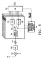
- FIG. 7 illustrates a structure of a UE for performing the transmit diversity control process shown in FIG. 4D ;
- FIG. 8 illustrates a structure of a Node B for performing the transmit diversity control process shown in FIG. 4D ;
- FIG. 9 illustrates a flow chart of a procedure for transmitting PDSCH/E-DSCH on the basis of a transmission time point according to a seventh embodiment of the present invention.
- FIG. 4A illustrates a transmit diversity control process according to a first embodiment of the present invention.
- FIG. 4B illustrates a transmit diversity control process according to a second embodiment of the present invention.
- FIG. 4C illustrates a transmit diversity control process according to a third embodiment of the present invention.
- FIG. 4D illustrates a transmit diversity control process according to a fourth embodiment of the present invention.
- FIG. 4E illustrates a transmit diversity control process according to a fifth embodiment of the present invention.
- FIG. 4F illustrates an internal structure of a transmit antenna array channel measurer for performing different embodiments of the present invention.
- the number of Node Bs registered in the active set is shown as 2, for simplicity.
- the Node B used in the asynchronous W-CDMA system has the same operation as a BTS (Base station Transceiver Subsystem) in the synchronous CDMA-2000 system.
- BTS Base station Transceiver Subsystem
- a Node B1 401 a Node B currently communicating with a UE 411 , transmits both a DL-DPCH and a PDSCH to the UE 411 .
- a Node B2 403 a Node B newly added to an active set of the UE 411 , transmits only the DL-DPCH to the UE 411 when the UE 411 is located in an SHO region.
- the UE 411 receives both the PDSCH and the DL-DPCH from the Node B1 401 , but it receives only the DL-DPCH from the Node B2 403 .
- the UE 411 transmits FBI (Feedback information) included in the UL-DPCCH to the Node B1 401
- the UE 411 is located in the SHO region, and enables a new Node B, i.e., the Node B2 403 in the active set to transmit the DL-DPCH signal in a STTD (Space-Time block coded Transmit Diversity) mode or a single-antenna (SA) mode, even though a transmit antenna array (TxAA) mode is available.
- STTD Space-Time block coded Transmit Diversity
- SA single-antenna
- TxAA transmit antenna array
- the STTD a type of open loop antenna diversity scheme, is not subject to a feedback operation, so that there is no PDSCH signal loss due to soft combining on the CPICHs from both of the Node Bs.
- the SA since the SA uses a single antenna, it does not use diversity.
- TxAA weight information on an FBI D-field is actually valid only for the Node B1 401 . Therefore, the weight information is calculated depending on the CPICH transmitted from the Node B1 401 .
- the UE 411 enables both the current Node B1 401 and the Node B2 403 , newly added to the active set, to perform TxAA transmission, calculates weights from the information determined by combining the information received from the Node B1 401 and the Node B2 403 , and applies the calculated weights as PDSCH weights of the Node B1 401 .
- the present invention can resolve the problem that in the conventional system, the TxAA operation for the PDSCH does not show proper performance in the SHO region due to a difference between the actual weights and the calculated weights, when the PDSCH, the transmit antenna weight of which is set to the same value of those of the DL-DPCH, is equally used in both the Node B1 401 and the Node B2 403 .
- the DL-DPCH from the Node B2 403 is transmitted in the TxAA mode along with the PDSCH as shown in FIG. 4A , and the DL-DPCH left in the Node B1 401 is switched from the TxAA mode to the STTD or SA mode.
- the SA mode and the STTD mode can be used together in the same Node B, it is preferable to use the STTD mode rather than the SA mode. This is because the STTD scheme has a diversity effect equal to or better than that of the TxAA scheme, unless the data rate is extremely low. Even though the data rate is low, the STTD scheme, compared with the TxAA scheme, suffers from a decrease in SINR of a maximum of 2 dB, but has a simpler hardware structure.
- the DPCHs of the Node Bs other than the PDSCH serving cell transmit signals in the STTD or SA mode, while the PDSCH and DPCH of the PDSCH serving cell continue to operate in the TxAA mode. That is, the UB 411 receives TFCI of the DPCH, the TFCI including the PDSCH transmission start information from the PDSCH serving cell, 5 slots before the PDSCH is transmitted. Upon receiving the TFCI from the PDSCH serving cell, the UE 411 can recognize that the PDSCH will be received prior to its transmission. Therefore, the UB 411 separately creates weights proper only for the PDSCH serving cell, at predetermined time slots before the PDSCH is received, and then feeds back the created weights using the FBI of the UL-DPCCH.
- the UE in the SHO region receives the DPCH, or the DPCH with the PDSCH according to the transmission condition.
- the UE feeds back the FBI of the UL-DPCCH to the respective Node Bs in the active set.
- the Node B transmitting the DPCH including the PDSCH continues to operate in the TxAA mode using the FBI information, while the other Node Bs simply transmitting only the DPCH do not use the FBI information and enable their DPCHs to operate in the STTD or SA mode.
- the SA mode includes the TxAA mode where the diversity gain is not obtained by disregarding the FBI or using the previous value.
- a mode of the non-DSCH serving cell having been operating in the STTD or SA mode returns to the TxAA mode, and the UE returns to a pre-DSCH transmission state where the UE calculates weights using the phase difference between the CPICHs transmitted from the Node Bs and then feeds back the calculated weights to the Node Bs.
- the STTD scheme is a type of open loop-mode antenna transit diversity scheme, and if STTD encoding is performed on a data signal A having a format constructed such that symbols S 1 and S 2 are sequentially input in transmit diversity encoding periods T 1 and T 2 , respective, then the consecutive symbols S 1 S 2 are output as S 1 S 2 through a first antenna and as ⁇ S 2 *S 1 * through a second antenna.
- the above-stated symbol STTD encoding will be described again in a channel bit unit.
- the received symbols S 1 S 2 become the channel bits b 0 b 1 b 2 b 3 .
- the channel bits b 0 b 1 b 2 b 3 are subject to the STTD encoding, the channel bits b 0 b 1 b 2 b 3 (S 1 S 2 ) are output through through the first antenna and the channel bits ⁇ b 2 b 3 b 0 ⁇ b 1 ( ⁇ S 2 *S 1 *) are output through the second antenna.
- the first antenna is a reference antenna and the second antenna is a diversity antenna.
- the DL-DPCH is transmitted in the STTD or SA mode in both a Node B1 421 and a Node B2 423 .
- the PDSCH being transmitted by only the Node B1 421 is transmitted in the TxAA mode. That is, by using the TxAA only for the PDSCH used for data transmission despite performance degradation of the DL-DPCH, an overall loss of the PDSCH signal is decreased, making it possible to ensure reliable data transmission.
- a dedicated pilot channel included in the DL-DPCH from the Node B2 421 should additionally include information for PDSCH demodulation.
- a method for additionally including the information for the PDSCH demodulation includes TDM (Time Division Multiplexing)/CDM (Code Division Multiplexing)/FDM (Frequency Division Multiplexing)/Space Time Coded-DM/additional or field modifying methods. It is preferable to consider using the TDM, given that the UE receiving the PDSCH has a low data rate.
- the DL-DPCH is transmitted in the STTD or SA mode in both the Node B1 421 and the Node B2 423 , while the PDSCH being transmitted by only the Node B1 421 is transmitted in the TxAA mode using the FBI of the UL-DPCH.
- the UE 431 receives TFCI including the transmission start information from the PDSCH serving cell, 5 slots before the PDSCH is transmitted, and then recognizes that the PDSCH will be received prior to its transmission.
- the UE 411 creates weights proper only for the PDSCH serving cell, at predetermined time slots before the PDSCH is received, and then feeds back the created weights. In addition, if only the DPCH is received after completion of transmitting the PDSCH, the UE returns to a pre-DSCH transmission state.
- the Node B1 441 transmitting the PDSCH is set to operate in the STTD or SA mode, even though the PDSCH has operated in the TxAA mode.
- the DL-DPCH operates in the TxAA mode in both the Node B1 441 and the Node B2 443 .
- the PDSCH will show better performance in the TxAA mode than in the STTD or SA mode.
- the TxAA scheme applies the weights calculated from the two Node Bs, i.e., the Node B1 441 and the Node B2 443 , the weights are different from the weights to be actually applied, thus causing an improper weight application problem, and additionally there occurs a feedback error and delay error, decreasing the performance compared with the SA scheme. Therefore, it is preferable to operate the PDSCH in the STTD or SA mode rather than in the TxAA mode. In this case, however, by using the TxAA for the DPCH, it is possible to obtain better performance for the DPCH having the high throughput and QoS (Quality of Service).
- QoS Quality of Service
- the DL-DPCH is transmitted in the TxAA mode in both the Node B1 441 and the Node B2 443 , while the PDSCH being transmitted by only the Node B1 441 is transmitted in the STTD or SA mode.
- the UE 451 calculates weights depending on a phase difference between the CPICHs transmitted from the Node Bs in the same manner.
- the UE if only the DPCH is received after completion of transmitting the PDSCH, the UE returns to a pre-DSCH transmission state.
- the UE 471 creates an additional separate FBI field# 2 for the PDSCH in the UL-DPCCH and transmits the created FBI field# 2 to the Node B1 461 . That is, the UE 471 calculates two different weights and transmits the created weights with FBI field# 1 for the DPCH and FBI field# 2 for the PDSCH in the UL-DPCH.
- the method for additionally creating the FBI field includes TDM/CDM/FDM/additional or field modifying methods. It is preferable to use TDM, given that the UE receiving the PDSCH has a low data rate.
- the method for separating the FBI field into the FBI field# 1 and the FBI field# 2 by TDM multiplexing is shown in Table 5.
- one FBI field is used, so that I and Q values of the weight symbols are alternately transmitted on a two-slot unit basis.
- two symbols are continuously transmitted in a manner of I 0 , I 1 , Q 0 , Q 1 .
- I 0 +Q 0 is a TxAA weight symbol for the DL-DPCH
- I 1 +Q 1 is a TxAA weight symbol for the PDSCH. It is assumed in Table 5 that a ratio of weight information of the DL-DPCH to weight information of the PDSCH is 1:1.
- the ratio can be changed according to the operation mode and the channel environment.
- Table 6 shows a slot format used when the weights of the different Node Bs are sent using the FBI field of the PDSCH. In this case, it is necessary to additionally set a field for transmitting the TxAA weights in the UL-DPCCH.
- the additional field is implemented by using an SSDT field (S field of the FBI) or a pilot field.
- a method for applying a transmit weight for the PDSCH operates in the same manner as the conventional method, but it identifies a primary Node B using SSDT signaling and then determines whether to increase or maintain PDSCH transmission power before transmission.
- the weights for the transmit diversity are used by the PDSCH as well as the DL-DPCH in the two Node Bs in the same manner as the conventional method.
- the SSDT signaling should be used not only when the SSDT is used but also when the DL-DPCH including the PDSCH enters the SHO region.
- the Node B1 481 Upon receiving primary cell information through the SSDT signaling, the Node B1 481 transmits the PDSCH without additionally increasing the transmission power.
- the Node B1 481 Upon receiving non-primary cell information, the Node B1 481 applies a power offset to the PDSCH before transmission.
- a transmission power offset a transmission power offset higher than when the PDSCH uses the TxAA scheme is used.
- a transmit diversity offset for the SA scheme, a transmission power offset for the STTD scheme and a transmission power offset for the TxAA scheme should be set to have independent values according to the transmit diversity mode of the PDSCH.
- the UE 491 located in the SHO region assigns temporary IDs (identifications) to the respective Node Bs in its active set, i.e., the Node B1 481 and the Node B2 483 , and then, selects a Node B capable of better satisfying the received signal quality of the UE 491 among the Node Bs.
- the Node B transmitting the DL-DPDCH is called a primary Node B, and the primary Node B is periodically updated depending on information measured by the UE 491 .
- the UE 491 Upon receiving CPICHs transmitted from the Node B1 481 and the Node B2 483 , the UE 491 compares pilot signal levels of the received CPICHs and determines the primary Node B depending on the compared results. Further, the UE 491 transmits the temporary ID previously set for the determined primary Node B to the other Node Bs, i.e., the Node B2 483 . In FIG.
- the Node B1 481 is a Node B transmitting the DL-DPCH and the PDSCH to the UE 491
- the Node B2 483 is a Node B newly added to the active set, which transmits only the DL-DPCH to the UE 491 .
- the Node B1 481 determines the transmission power of the PDSCH by applying the TPC bits of the DL-DPCH, and transmits the signals at the normal transmission power considering that an influence due to the TxAA weights is minimized. That is, whether to increase or decrease the transmission power of the PDSCH is determined depending on the TPC bits transmitted by the UE 491 .
- a transmission power control operation including the TxAA operation of the PDSCH is performed in the same manner as when the UE 491 is located in the non-SHO region.
- the Node B1 481 having been serving as the primary Node B is redefined as a secondary Node B and the Node B2 483 having been serving as the secondary Node B is redefined as the primary Node B
- the Node B1 481 estimates that the distance from the UE 491 has increased or the channel environment is bad, applies a fixed transmission power offset to the transmission power of the PDSCH and transmits it to the UE 491 . Thereafter, in the period where information on the primary Node B is updated, the Node B controls transmission power of the PDSCH depending on the TPC bits transmitted by the UE 491 .
- the TxAA scheme is used for the PDSCH in the SHO region, different values must be used for the fixed transmission power offset according to the diversity modes.
- the UE receiving the PDSCH exists in the SHO region and the Node B transmitting the PDSCH transmits the PDSCH using the closed-loop transmit antenna diversity
- the UE additionally assigns a new UL-DPCCH.
- the UL-DPCCH transmitted to the Node B when the UE first uses the PDSCH will be referred to as “UL-DPCCH1”
- the additional UL-DPCCH newly added when the UE is located in the SHO region will be referred to as “UL-DPCCH2”.
- the reason that the UL-DPCCH is transmitted over the Q channel is to continuously transmit the UL-DPCCH even when the UE has no uplink data to transmit after a call setup, under the W-CDMA standard, and thus prevent discontinuous transmission of the uplink signal, thereby preventing electromagnetic interference.
- the UL-DPDCH transmitted along with the UL-DPCCH can use a spreading factor of 4 to 256. It is possible to transmit a maximum of 6 UL-DPDCHs.
- the newly assigned UL-DPCCH i.e., the UL-DPCCH 2
- the SF of the OVSF code to be used for the newly assigned UL-DPCCH 2 is changed to 128.
- the communication between the UE and the Node B is performed as follows.
- the UE transmits feedback information for controlling a closed-loop antenna gain of the DL-DPCHs transmitted by the Node Bs in the active set of the UE, created as the UE enters the SHO region, through the FBI field of the UL-DPCCH previously used before the UE is located in the SHO region, i.e., the UL-DPCCH 1 , and the UE transmits the feedback information only for the PDSCH to the Node B transmitting the PDSCH, over the FBI field of the newly used UL-DPCCH, i.e., the UL-DPCCH 2 , thereby properly controlling the respective antenna transmission gains for the PDSCH.
- the UE can obtain a sufficient closed-loop antenna diversity gain while receiving the PDSCH.
- the UL-DPCCH 1 can be used in transmitting the feedback information for controlling an antenna transmit parameter of the DL-DPCH.
- the feedback information for the PDSCH can be created by measuring the CPICH from the Node B transmitting the PDSCH, measuring the pilot field of the DL-DPCH, or directly measuring the PDSCH; and the feedback information for the DPCH can be created based on an optimal antenna gain parameter by summing up the CPICH signals transmitted from the respective Node Bs in the active set of the UE.
- weights applied to the TxAA scheme are determined depending on a receiving power level of the CPICH received from the Node B1, so that weight factors a 1 and a 2 are all set to ‘1’.
- the Node B1 is not the primary Node B
- the CPICH values are weighted with weight factors a 1 and a 2 (where a 1 >a 2 ) in order to increase reliability of the TxAA weights used for the PDSCH, and then provided to a TxAA weight decision device 495 .
- the TxAA weight decision device 495 differently creates the weights to be provided to all the cell in the active set according to the circumstances.
- H i (where i denotes an ID number of the Node B) indicates a channel matrix, w indicates an antenna weight, and a i indicates a weight factor for the Node B i .
- FIG. 5 illustrates a flowchart for the transmit diversity control process shown in FIG. 4A .
- the UE 411 determines whether the DL-DPCH with the PDSCH and the PDSCH received from the Node B1 401 operate in the TxAA mode (Step 503 ). If it is determined that the PDSCH and the DL-DPCH do not operate in the TxAA mode, the UE 411 returns to Step 500 .
- the UE 411 determines whether it is located in the SHO region (Step 505 ). If it is determined that the UE 411 is located in a non-SHO region, the UE 411 returns to Step 500 . If, however, it is determined that the UE 411 is located in the SHO region, the UE 411 determines whether the DL-DPCH of the Node B2 403 , i.e., the other Node B except the current Node B1 401 is added to the active set (Step 507 ).
- Step 513 the UE 411 determines whether the Node B whose DL-DPCH is added to the active set can operate in the TxAA mode (Step 509 ). If it is determined that the Node B whose DL-DPCH is added to the active set cannot operate in the TxAA mode, the UE 411 proceeds to Step 513 .
- the UE 411 determines whether the PDSCH is handed over (Step 513 ). If it is determined that the PDSCH is not handed over, the UE 411 proceeds to Step 519 . Otherwise, if it is determined that the PDSCH is handed over, the UE 411 determines whether the Node B1 401 uses the TxAA mode (Step 515 ).
- the UE 411 determines whether the Node B2 403 can use the TxAA mode (Step 519 ). If it is determined that the Node B2 403 cannot use the TxAA mode, the UE 411 returns to Step 500 . However, if it is determined that the Node B2 403 can use the TxAA mode, the UE 411 enables the TxAA mode of the Node B2 403 and then ends the operation (Step 521 ).
- FIG. 6 illustrates a structure of a UE for performing the transmit diversity control process shown in FIG. 4A .
- an input signal of the UE 411 is received through an antenna 701 and then provided to a down-converter 702 .
- the down-converter 702 down-converts the received signal by mixing it with a composite frequency f c and provides the down-converted signal to a lowpass filter (LPF) 703 .
- the lowpass filter 703 lowpass-filters the down-converted signal output from the down-converter 702 and provides the filtered baseband signal to an analog-to-digital (A/D) converter 704 .
- the A/D converter 704 converts the analog baseband signal output from the lowpass filter 703 to a digital signal and provides the converted digital signal to a finger# 1 .
- a common processor 705 commonly processes the digital signal output from the A/D converter 704 in the TxAA mode and the STTD mode and provides its output to a switch 706 .
- the switch 706 under the control of a transmit diversity mode selection controller (or transmit diversity mode selection controller for DL-DPCH/PDSCH during SHO) 710 , switches the output of the common processor 705 to a TxAA mode processor 707 or an STTD/SA mode processor 708 , and then the switched signals output from the TxAA mode processor 707 and the STTD/SA mode processor 708 are provided to a digital signal processor (DSP) 709 .
- the transmit diversity mode selection controller 710 operates in accordance with an algorithm shown in FIG. 5 . In FIG.
- the DSP 709 processes the digital data for a service required by the UE 411 using the results output from the TxAA mode processor 707 or the STTD/SA mode processor 708 , and transmits the processed data to an upper layer.
- FIG. 7 illustrates a structure of a UE for performing the transmit diversity control process shown in FIG. 4D .
- a radio signal in the air is received through an antenna 801 and then provided to a down-converter 802 .
- the down-converter 802 down-converts the received radio signal by multiplying with a predetermined composite frequency f c and provides its output signal to an LPF 803 .
- the LPF 803 lowpass-filters the signal output from the down-converter 802 and provides the lowpass-filtered analog signal to an A/D converter 804 .
- the A/D converter 804 converts the analog signal output from the LPF 803 to a digital signal and provides the converted digital signal a first finger Finger# 1 and a second finger Finger# 2 .
- the first finger is for processing the signals received from the Node B1 461
- the second is for processing the signals received from the Node B2 463 of FIG. 4D .
- a descrambler 805 descrambles the output signal of the A/D converter 804 by multiplying with a scrambling code C SC,1 for the Node B1 461 .
- a despreader 806 despreads the output signal of the descrambler 805 by multiplying it by a spreading code C SP,1 for the Node B1 461 .
- An accumulator 807 accumulates the output signal of the despreader 806 and provides the accumulated signal to a weight generator 811 .
- a descrambler 808 descrambles the output signal of the A/D converter 804 by multiplying with a scrambling code C SC,2 for the Node B2 463 .
- a second despreader 809 despreads the output signal of the descrambler 808 by multiplying it by a spreading code C SP,2 for the Node B2 463 .
- An accumulator 810 accumulates the output signal of the second despreader 809 and provides the accumulated signal to an adder 812 .
- the adder 812 adds the output signal of the accumulator 807 to the output signal of the accumulator 810 , and provides its output to a weight generator 813 .
- FIG. 8 illustrates a structure of a Node B for performing the transmit diversity control process shown in FIG. 4D .
- radio signals in the air received from the UE 471 through a first antenna (ANT 1 ) 859 and a second antenna (ANT 2 ) 860 are provided to a demultiplexer (DEMUX) 852 .
- the DEMUX 852 detects feedback information (FBI) from DPCCH signals of the radio signals received through the first and second antennas 859 and 860 , and provides the detected feedback information to a weight generator 851 .
- FBI feedback information
- a multiplexer (MUX) 853 multiplexes a DPDCH signal and a DPCCH signal into a DPCH (Dedicated Physical Channel) signal, and provides the DPCH signal to a multiplier 854 .
- the multiplier 854 multiplies the DPCH signal output from the MUX 853 by a spreading and scrambling code for the Node B1 461 , and provides its output signal to the multiplier 855 and the multiplier 856 .
- the multiplier 855 multiplies the weight w 11 output from the weight generator 851 by the output signal of the multiplier 854 , and provides its output to a summer 857 .
- the multiplier 856 multiplies the weight W 12 output from the weight generator 851 by the output signal of the multiplier 854 , and provides its output to a summer 858 .
- a multiplier 862 multiplies a PDSCH signal by a spreading and scrambling code for the Node B1 461 and provides its output to the multiplier 863 and the multiplier 864 .
- the multiplier 863 multiplies the weight w 21 output from the weight generator 851 by the output signal of the multiplier 862 , and provides its output to the summer 857 .
- the multiplier 864 multiplies the weight w 22 output from the weight generator 851 by the output signal of the multiplier 862 , and provides its output to the summer 858 .
- the summer 857 sums up the output signal of the multiplier 855 , the output signal of the multiplier 863 and a first common pilot channel signal (CPICH 1 ), and transmits the summed signal through the first antenna 859 .
- the summer 858 sums up the output signal of the multiplier 856 , the output signal of the multiplier 864 and a second common pilot channel signal (CPICH 2 ), and transmits the summed signal through the second antenna 860 . Accordingly, it is possible to apply different weights to the DL-DPCH signal and the PDSCH signal based on the feedback information of the UP-DPCCH signal received from the UE 471 .
- the enhanced PDSCH (E-PDSCH) supporting the FCS will operate as follows.
- the FCS determines from which Node B the UE is to receive data, and provides the Node B with the corresponding information. Therefore, if the UE determines the Node B which will transmit the E-PDSCH, based on the FCS, then the UE creates weights proper for the E-PDSCH serving cell, and then transmits the created weights to the E-PDSCH serving cell using the FBI.
- the UE previously recognizes an arrival time of the E-PDSCH by receiving the TFCI bits including information on the transmission start point from the E-PDSCH serving cell, and thus switches to the above-stated modes, i.e., the modes of FIGS. 4A to 4F .
- the target Node B calculating the weights is dynamically changed according to the Node B determined by the UE.
- the UE can transmit FSM (Finite States Machine, a type of shift register) bit information of the TxAA FBI, beginning at a next bit of the previous bit position, not at the initial bit. If the UE changed the cell or failed to receive the just previous frame, the UE retransmits the FSM bits from the initial bit. However, when the UE simply transmits the FMS bit information in the same format like in Mode# 1 of 3GPP (or UMTS W-CDMA), it is possible to continuously transmit the FSM bits of the FBI regardless of whether the cell is determined based on the FCS.
- FSM Finite States Machine, a type of shift register
- the E-PDSCH and the normal PDSCH use the information transmitted by the E-PDSCH and the PDSCH in the SHO region, the E-PDSCH and the PDSCH must operate in accordance with the number of slots for transmitting the FBI, required by the TxAA.
- FIG. 9 illustrates a procedure for transmitting PDSCH/E-PDSCH on the basis of a transmission time point according to a seventh embodiment of the present invention.
- the UE performs a general DPCH TxAA mode (Step 911 ).
- the UE determines whether the PDSCH/E-DSCH is received from the Node B in the DPCH TxAA mode (Step 913 ). If it is determined that the PDSCH/E-DSCH is not received from the Node B, the UE performs the general DPCH TxAA mode (Step 911 ).
- the UE if it is determined that the PDSCH/E-DSCH is received from the Node B, the UE repeatedly selects a Node B having a good channel condition depending on the FCS, thereby increasing the reliability and minimizing the determination time. That is, in the SHO region, the UE repeatedly selects a Node B having the best channel condition among a plurality of Node Bs from which signals are received, using the FCS, thereby selecting the Node B having the best channel condition.
- the UE determines whether data is received from the same Node B on a time-sequence basis (Step 915 ).
- the UE If it is determined that the data is received from the same Node B on a time-sequence basis, the UE maintains a TxAA FBI FSM index in Mode# 1 using 2 bits, and initializes the TxAA FBI FSM index to ‘0’ in Mode# 2 using 4 bits (Step 917 ). If the data is received from the same Node B on a time-sequence basis, the UE applies the new data output on the basis of the previous result.
- the UE applies a new value on the basis of a predetermined offset or the result which was previously applied to another Node B, and then performs PDSCH/E-DSCH addition, creation and feedback, or PDSCH/E-DSCH mode switching between the TxAA mode and the STTD/SA mode (Step 919 ). Thereafter, the UE determines whether transmission/reception of the PDSCH/E-DSCH is completed (Step 921 ). If it is determined that transmission/reception of the PDSCH/E-DSCH is completed, the UE changes its operation mode from the STTD or SA mode to the DPCH TxAA mode (Step 911 ). Otherwise, if it is determined that transmission/reception of the PDSCH/E-DSCH is not completed, the UE determines again whether the PDSCH/E-DSCH is received from the Node B (Step 913 ).
- the UE can control a transmit antenna array for the PDSCH, making it possible to apply proper transmit antenna diversity weights.
- the UE can control the transmit antenna array for the E-PDSC H /PDSCH, making it possible to apply the proper transmit antenna weights.
- the UE can separately apply a transmit antenna weight for the PDSCH and a transmit antenna weight for the DL-DPCH, thereby resolving the problem caused by the conventional SHO scheme that the applied weights are different from the proper transmit antennas weights due to the use of the same transmit antenna weights for the DPSCH and the DL-DPCH.
Landscapes
- Engineering & Computer Science (AREA)
- Computer Networks & Wireless Communication (AREA)
- Signal Processing (AREA)
- Physics & Mathematics (AREA)
- Mathematical Physics (AREA)
- Computer Security & Cryptography (AREA)
- Mobile Radio Communication Systems (AREA)
- Radio Transmission System (AREA)
Applications Claiming Priority (6)
| Application Number | Priority Date | Filing Date | Title |
|---|---|---|---|
| KR2000-59869 | 2000-10-11 | ||
| KR20000059869 | 2000-10-11 | ||
| KR20000070579 | 2000-11-24 | ||
| KR2000-70579 | 2000-11-24 | ||
| KR2001-10926 | 2001-03-02 | ||
| KR20010010926 | 2001-03-02 |
Publications (2)
| Publication Number | Publication Date |
|---|---|
| US20020131381A1 US20020131381A1 (en) | 2002-09-19 |
| US7277407B2 true US7277407B2 (en) | 2007-10-02 |
Family
ID=27350336
Family Applications (1)
| Application Number | Title | Priority Date | Filing Date |
|---|---|---|---|
| US09/975,419 Expired - Fee Related US7277407B2 (en) | 2000-10-11 | 2001-10-11 | Apparatus and method for controlling transmit antenna array for physical downlink shared channel in a mobile communication system |
Country Status (9)
| Country | Link |
|---|---|
| US (1) | US7277407B2 (ko) |
| EP (2) | EP1791268A3 (ko) |
| JP (1) | JP3786918B2 (ko) |
| KR (1) | KR100396272B1 (ko) |
| CN (1) | CN1233110C (ko) |
| AU (1) | AU766372B2 (ko) |
| CA (1) | CA2394093C (ko) |
| DE (1) | DE60133524T2 (ko) |
| WO (1) | WO2002032017A1 (ko) |
Cited By (12)
| Publication number | Priority date | Publication date | Assignee | Title |
|---|---|---|---|---|
| US20040082311A1 (en) * | 2002-10-28 | 2004-04-29 | Shiu Da-Shan | Utilizing speed and position information to select an operational mode in a wireless communication system |
| US20050026622A1 (en) * | 2003-06-24 | 2005-02-03 | Nortel Networks Limited | Method of controlling access to resources of a radiocommunication network and base station for implementing the method |
| US20050111376A1 (en) * | 2003-11-21 | 2005-05-26 | Nokia Corporation | Flexible rate split method for MIMO transmission |
| US20050143080A1 (en) * | 2001-08-20 | 2005-06-30 | Ragulan Sinnarajah | Method and system for signaling in broadcast communication system |
| US20050201321A1 (en) * | 2003-09-11 | 2005-09-15 | Ragulan Sinnarajah | Method and system for signaling in broadcast communication system |
| US20060028995A1 (en) * | 2004-08-05 | 2006-02-09 | Canoy Michael-David N | Method and apparatus for receiving broadcast in a wireless multiple-access communications system |
| US20060154614A1 (en) * | 2002-04-22 | 2006-07-13 | Burkhard Becker | Device for calculating fsm bits in the umts standard |
| US20070243871A1 (en) * | 2001-08-20 | 2007-10-18 | Qualcomm, Incorporated | Method and system for a handoff in a broadcast communication system |
| US20070298798A1 (en) * | 2004-08-06 | 2007-12-27 | Telefonaktiebolaget Lm Ericsson (Publ) | Method and System of Radio Communications |
| US20090086700A1 (en) * | 2003-10-02 | 2009-04-02 | Qualcomm Incorporated | Systems and methods for communicating control data using multiple slot formats |
| US20160330668A1 (en) * | 2003-08-25 | 2016-11-10 | Signal Trust For Wireless Innovation | Enhanced uplink operation in soft handover |
| US10219196B2 (en) | 2003-11-05 | 2019-02-26 | Signal Trust For Wireless Innovation | Supporting enhanced uplink transmission during soft handover |
Families Citing this family (66)
| Publication number | Priority date | Publication date | Assignee | Title |
|---|---|---|---|---|
| AU2000238190A1 (en) * | 2000-04-07 | 2001-10-23 | Nokia Corporation | Multi-antenna transmission method and system |
| JP3440076B2 (ja) * | 2000-11-29 | 2003-08-25 | 松下電器産業株式会社 | 無線インフラ装置 |
| JP3679000B2 (ja) | 2000-12-21 | 2005-08-03 | 松下電器産業株式会社 | 無線送信装置及び無線送信方法 |
| JP3543770B2 (ja) * | 2001-02-20 | 2004-07-21 | 日本電気株式会社 | 移動通信システム、移動端末及びそれらに用いる送信ダイバーシチ適用方法並びにそのプログラム |
| DE10141392A1 (de) * | 2001-08-23 | 2003-03-06 | Siemens Ag | Verfahren zum Steuern der Strahlformung in einem Mobilfunk-Kommunikationssystem, Handover-Verfahren und Basisstation dafür |
| KR20030033192A (ko) * | 2001-10-18 | 2003-05-01 | 주식회사 세스텍 | 스마트 안테나 시스템에서 심볼레이트와 칩레이트를혼용하여 웨이팅하는 핑거와, 그를 이용한 복조 장치 및방법 |
| JP4012391B2 (ja) | 2001-10-30 | 2007-11-21 | 株式会社エヌ・ティ・ティ・ドコモ | 移動局、移動通信システム、ハンドオーバー制御方法、ハンドオーバー制御プログラム、及び記録媒体 |
| US7133461B2 (en) * | 2001-12-14 | 2006-11-07 | Motorola, Inc. | Stream transmission method and device |
| KR100459431B1 (ko) * | 2002-08-20 | 2004-12-03 | 엘지전자 주식회사 | 무선 이동 통신 시스템에서 하향 공유 채널 전송 전력제어방법 |
| WO2003084099A1 (fr) * | 2002-04-03 | 2003-10-09 | Nec Corporation | Systeme de communication mobile, station mobile, station de base, procede d'estimation de la qualite de la voie de communication utilise dans ce systeme |
| KR101232666B1 (ko) * | 2002-05-01 | 2013-02-13 | 인터디지탈 테크날러지 코포레이션 | 무선 통신 시스템에서 공유 채널을 사용한 지점대 다지점간 서비스 |
| TW587882U (en) | 2002-05-01 | 2004-05-11 | Interdigital Tech Corp | Node-B capable of supporting point to multi-point services using high speed channels |
| KR100899735B1 (ko) * | 2002-07-03 | 2009-05-27 | 삼성전자주식회사 | 이동 통신 시스템에서 적응적 전송 안테나 다이버시티장치 및 방법 |
| US6922560B1 (en) * | 2002-08-20 | 2005-07-26 | National Semiconductor Corporation | Method and system for antenna verification for closed loop transmit diversity |
| US7236479B2 (en) * | 2002-10-08 | 2007-06-26 | Samsung Electronics Co., Ltd. | Apparatus and method for controlling transmission antenna arrays for a high speed physical downlink shared channel in a mobile communication system |
| KR100538024B1 (ko) * | 2002-11-08 | 2005-12-20 | 한국전자통신연구원 | 무선 송수신 시스템 및 그 송수신 방법 |
| US20040116146A1 (en) * | 2002-12-13 | 2004-06-17 | Sadowsky John S. | Cellular system with link diversity feedback |
| US20040132494A1 (en) * | 2003-01-03 | 2004-07-08 | Olav Tirkkonen | Communication method |
| JP4300056B2 (ja) * | 2003-04-25 | 2009-07-22 | 株式会社リコー | 概念表現生成方法、プログラム、記憶媒体及び概念表現生成装置 |
| JP4167536B2 (ja) | 2003-04-25 | 2008-10-15 | 松下電器産業株式会社 | 基地局装置、基地局制御装置 |
| KR100575930B1 (ko) * | 2003-05-16 | 2006-05-02 | 삼성전자주식회사 | 송신다이버시티를 사용하는 이동통신 시스템에 있어송신다이버시티의 방식 전환 장치 및 방법 |
| GB0311856D0 (en) * | 2003-05-22 | 2003-06-25 | Nokia Corp | Transmissions from a station with multiple antennae |
| DE10336804A1 (de) * | 2003-08-11 | 2005-03-31 | Siemens Ag | Verfahren zur Datenübertragung |
| US7224941B2 (en) * | 2003-10-20 | 2007-05-29 | Accton Technology Corporation | System and method for multi-path simulation |
| DE10351051A1 (de) * | 2003-10-31 | 2005-06-09 | Infineon Technologies Ag | Vertifikation der Antennengewichte der Basisstation in einem UMTS-Mobilfunkempfänger durch Verwendung des Viterbi-Algorithmus bei der rückgekoppelten Sendediversität |
| CN1898880A (zh) * | 2003-12-22 | 2007-01-17 | 皇家飞利浦电子股份有限公司 | 具有用于使干扰最小的装置的数据接收机和使用在这种接收机中的方法 |
| AU2005213087B2 (en) * | 2004-02-14 | 2008-07-31 | Samsung Electronics Co., Ltd. | Apparatus and method for allocating OVSF codes and I/Q channels for reducing Peak-To-Average Power Ratio in transmitting data via enhanced up-link dedicated channels in WCDMA systems |
| KR100744336B1 (ko) * | 2004-06-18 | 2007-07-30 | 삼성전자주식회사 | Ofdm기반의 무선 통신 시스템에서의 핸드오버 방법 |
| JP4636232B2 (ja) * | 2004-07-09 | 2011-02-23 | 日本電気株式会社 | 移動通信システムにおけるパケット転送方法およびその通信システム |
| CN1750424A (zh) * | 2004-09-15 | 2006-03-22 | 华为技术有限公司 | 一种用于宽带码分多址上行增强链路的功率偏置控制方法 |
| CN101023602B (zh) * | 2004-09-17 | 2012-12-19 | 株式会社Ntt都科摩 | 移动通信方法、移动台和基站 |
| KR100938091B1 (ko) * | 2004-10-13 | 2010-01-21 | 삼성전자주식회사 | 직교주파수다중분할 이동통신시스템에서 블록 부호화기법과 순환 지연 다이버시티 기법을 사용하는 기지국송신 장치 및 방법 |
| JP4785377B2 (ja) * | 2004-12-14 | 2011-10-05 | 株式会社エヌ・ティ・ティ・ドコモ | 無線回線制御局、移動通信システム及び移動通信方法 |
| JP4559240B2 (ja) | 2005-01-13 | 2010-10-06 | 株式会社エヌ・ティ・ティ・ドコモ | 移動通信システム、無線基地局、無線回線制御局及び電力制御方法 |
| JP4614798B2 (ja) * | 2005-03-16 | 2011-01-19 | 富士通株式会社 | 移動局および重み付け制御方法 |
| US7499439B2 (en) * | 2005-06-03 | 2009-03-03 | Alcatel-Lucent Usa Inc. | Method for controlling transmission rates in a wireless communications system |
| US8630602B2 (en) * | 2005-08-22 | 2014-01-14 | Qualcomm Incorporated | Pilot interference cancellation |
| US9014152B2 (en) | 2008-06-09 | 2015-04-21 | Qualcomm Incorporated | Increasing capacity in wireless communications |
| US8594252B2 (en) * | 2005-08-22 | 2013-11-26 | Qualcomm Incorporated | Interference cancellation for wireless communications |
| US8611305B2 (en) * | 2005-08-22 | 2013-12-17 | Qualcomm Incorporated | Interference cancellation for wireless communications |
| US8743909B2 (en) * | 2008-02-20 | 2014-06-03 | Qualcomm Incorporated | Frame termination |
| US9071344B2 (en) * | 2005-08-22 | 2015-06-30 | Qualcomm Incorporated | Reverse link interference cancellation |
| KR101276797B1 (ko) * | 2005-08-24 | 2013-06-20 | 한국전자통신연구원 | 이동 통신 시스템에서의 송신 다이버시티 방법 및 기지국송신기 |
| JP4869802B2 (ja) * | 2006-06-19 | 2012-02-08 | 株式会社エヌ・ティ・ティ・ドコモ | 送信装置及び通信方法 |
| US8032091B2 (en) * | 2007-03-14 | 2011-10-04 | Magnolia Broadband Inc. | Method, apparatus and system for providing transmit diversity feedback during soft handoff |
| US8699968B2 (en) | 2007-03-14 | 2014-04-15 | Google Inc. | Using multiple and a single feedback for UE uplink beamforming in soft handoff |
| CN101472305B (zh) * | 2007-12-26 | 2012-01-25 | 电信科学技术研究院 | 一种实现小区切换的方法、系统及装置 |
| CN101217305B (zh) * | 2008-01-02 | 2011-05-04 | 华为技术有限公司 | 专用物理数据信道数据的处理方法和装置 |
| EP2107696A1 (en) * | 2008-03-31 | 2009-10-07 | Mitsubishi Electric R&D Centre Europe B.V. | Method and device for managing a set of base stations of a wireless cellular telecommunication network |
| US9237515B2 (en) | 2008-08-01 | 2016-01-12 | Qualcomm Incorporated | Successive detection and cancellation for cell pilot detection |
| US9277487B2 (en) | 2008-08-01 | 2016-03-01 | Qualcomm Incorporated | Cell detection with interference cancellation |
| ES2354538B1 (es) * | 2008-08-14 | 2012-01-26 | Vodafone España, S.A. | Sistema y método de conmutación dinámica entre transmisión de una única antena y múltiples antenas. |
| WO2010072020A1 (en) * | 2008-12-22 | 2010-07-01 | Huawei Technologies Co., Ltd. | Method for signalling in a wireless communication system |
| US9160577B2 (en) * | 2009-04-30 | 2015-10-13 | Qualcomm Incorporated | Hybrid SAIC receiver |
| US8787509B2 (en) | 2009-06-04 | 2014-07-22 | Qualcomm Incorporated | Iterative interference cancellation receiver |
| US8831149B2 (en) | 2009-09-03 | 2014-09-09 | Qualcomm Incorporated | Symbol estimation methods and apparatuses |
| CN102035777B (zh) * | 2009-09-24 | 2014-03-12 | 中兴通讯股份有限公司 | 解调导频的处理方法和系统、配置方法、基站、用户设备 |
| US20110294493A1 (en) * | 2009-11-25 | 2011-12-01 | Qualcomm Incorporated | Modulating cell information on a physical channel |
| WO2011063568A1 (en) | 2009-11-27 | 2011-06-03 | Qualcomm Incorporated | Increasing capacity in wireless communications |
| WO2011063569A1 (en) | 2009-11-27 | 2011-06-03 | Qualcomm Incorporated | Increasing capacity in wireless communications |
| US9295047B2 (en) | 2011-04-29 | 2016-03-22 | Lg Electronics Inc. | Method for transmitting and receiving downlink control information in a wireless communication system and apparatus for the same |
| US9178680B2 (en) * | 2012-03-23 | 2015-11-03 | Alcatel Lucent | Control signaling for downlink coordinated multipoint wireless communication |
| US9307521B2 (en) * | 2012-11-01 | 2016-04-05 | Samsung Electronics Co., Ltd. | Transmission scheme and quasi co-location assumption of antenna ports for PDSCH of transmission mode 10 for LTE advanced |
| CN104995939A (zh) * | 2013-01-11 | 2015-10-21 | 华为技术有限公司 | 获取天线增益的方法、设备和系统 |
| US9961600B2 (en) * | 2016-06-30 | 2018-05-01 | Qualcomm Incorporated | Techniques for employing antenna switched diversity in wireless communications |
| CN109066419B (zh) * | 2018-08-28 | 2020-06-26 | 国网河北省电力有限公司电力科学研究院 | 二次设备检修安全措施操作的诊断方法、系统及终端设备 |
Citations (18)
| Publication number | Priority date | Publication date | Assignee | Title |
|---|---|---|---|---|
| US5101501A (en) * | 1989-11-07 | 1992-03-31 | Qualcomm Incorporated | Method and system for providing a soft handoff in communications in a cdma cellular telephone system |
| EP0966125A1 (en) | 1998-06-15 | 1999-12-22 | Motorola, Inc. | Method and apparatus for improving capacity in a radio communications system |
| US6067324A (en) | 1998-06-30 | 2000-05-23 | Motorola, Inc. | Method and system for transmitting and demodulating a communications signal using an adaptive antenna array in a wireless communication system |
| US6069912A (en) * | 1995-11-29 | 2000-05-30 | Ntt Mobile Communications Network, Inc. | Diversity receiver and its control method |
| WO2000036764A2 (en) | 1998-12-15 | 2000-06-22 | Nokia Networks Oy | Method and radio system for digital signal transmission |
| US6115406A (en) * | 1999-09-10 | 2000-09-05 | Interdigital Technology Corporation | Transmission using an antenna array in a CDMA communication system |
| US6205166B1 (en) * | 1997-08-05 | 2001-03-20 | Nec Corporation | CDMA receiver with antenna array adaptively controlled with combined errors of despread multipath components |
| US6333926B1 (en) * | 1998-08-11 | 2001-12-25 | Nortel Networks Limited | Multiple user CDMA basestation modem |
| US20020009061A1 (en) * | 2000-02-22 | 2002-01-24 | Serge Willenegger | Method and apparatus for controlling transmit power of multiple channels in a CDMA communication system |
| US6442193B1 (en) * | 1999-03-30 | 2002-08-27 | Koninklijke Philips Electronics N.V. | Combining sub-chip resolution samples in arms of a spread-spectrum rake receiver |
| US20020141331A1 (en) * | 2001-02-16 | 2002-10-03 | Nokia Mobile Phones Ltd. | Method and device for downlink packet switching |
| US6597678B1 (en) * | 1999-02-01 | 2003-07-22 | Hitachi, Ltd. | Radio communication system using adaptive array antenna |
| US6714584B1 (en) * | 1998-04-07 | 2004-03-30 | Nec Corporation | CDMA adaptive antenna receiving apparatus and communication system |
| US6724828B1 (en) * | 1999-01-19 | 2004-04-20 | Texas Instruments Incorporated | Mobile switching between STTD and non-diversity mode |
| US6816717B1 (en) * | 1999-03-30 | 2004-11-09 | Nokia Corporation | Estimation of signal to interference ratio in a mobile communication system |
| US6862275B1 (en) * | 1999-02-26 | 2005-03-01 | Texas Instruments Incorporated | Cell selection with STTD and SSDT |
| US6868075B1 (en) * | 1999-09-28 | 2005-03-15 | Telefonaktiebolaget Lm Ericsson (Publ) | Method and apparatus for compressed mode communications over a radio interface |
| US6904076B1 (en) * | 1998-03-05 | 2005-06-07 | Fujitsu Limited | Interference canceller device and radio communication device |
Family Cites Families (7)
| Publication number | Priority date | Publication date | Assignee | Title |
|---|---|---|---|---|
| TW351886B (en) * | 1993-09-27 | 1999-02-01 | Ericsson Telefon Ab L M | Using two classes of channels with different capacity |
| US5495873A (en) * | 1993-10-13 | 1996-03-05 | Benteler Industries, Inc. | Patterned air gap engine exhaust conduit |
| US6173005B1 (en) * | 1997-09-04 | 2001-01-09 | Motorola, Inc. | Apparatus and method for transmitting signals in a communication system |
| KR19990042478A (ko) * | 1997-11-27 | 1999-06-15 | 윤종용 | 반도체 소자 형성방법 |
| JP3589879B2 (ja) * | 1998-11-26 | 2004-11-17 | 松下電器産業株式会社 | 無線基地局装置及び送信電力制御方法 |
| KR100678263B1 (ko) * | 1999-02-10 | 2007-02-01 | 삼성전자주식회사 | 이동통신시스템에서 송신 안테나 다이버시티 제어방법 및 장치 |
| US6169759B1 (en) * | 1999-03-22 | 2001-01-02 | Golden Bridge Technology | Common packet channel |
-
2001
- 2001-10-11 WO PCT/KR2001/001712 patent/WO2002032017A1/en active IP Right Grant
- 2001-10-11 EP EP20070005503 patent/EP1791268A3/en not_active Withdrawn
- 2001-10-11 KR KR1020010062765A patent/KR100396272B1/ko not_active IP Right Cessation
- 2001-10-11 US US09/975,419 patent/US7277407B2/en not_active Expired - Fee Related
- 2001-10-11 EP EP20010124442 patent/EP1204219B1/en not_active Expired - Lifetime
- 2001-10-11 DE DE2001633524 patent/DE60133524T2/de not_active Expired - Lifetime
- 2001-10-11 AU AU96057/01A patent/AU766372B2/en not_active Ceased
- 2001-10-11 CN CNB018030955A patent/CN1233110C/zh not_active Expired - Fee Related
- 2001-10-11 CA CA 2394093 patent/CA2394093C/en not_active Expired - Fee Related
- 2001-10-11 JP JP2002535295A patent/JP3786918B2/ja not_active Expired - Fee Related
Patent Citations (20)
| Publication number | Priority date | Publication date | Assignee | Title |
|---|---|---|---|---|
| US5101501A (en) * | 1989-11-07 | 1992-03-31 | Qualcomm Incorporated | Method and system for providing a soft handoff in communications in a cdma cellular telephone system |
| US6069912A (en) * | 1995-11-29 | 2000-05-30 | Ntt Mobile Communications Network, Inc. | Diversity receiver and its control method |
| US6205166B1 (en) * | 1997-08-05 | 2001-03-20 | Nec Corporation | CDMA receiver with antenna array adaptively controlled with combined errors of despread multipath components |
| US6904076B1 (en) * | 1998-03-05 | 2005-06-07 | Fujitsu Limited | Interference canceller device and radio communication device |
| US6714584B1 (en) * | 1998-04-07 | 2004-03-30 | Nec Corporation | CDMA adaptive antenna receiving apparatus and communication system |
| EP0966125A1 (en) | 1998-06-15 | 1999-12-22 | Motorola, Inc. | Method and apparatus for improving capacity in a radio communications system |
| JP2000069570A (ja) | 1998-06-15 | 2000-03-03 | Motorola Inc | 無線通信システムにおいて容量を改善するための方法および装置 |
| US6067324A (en) | 1998-06-30 | 2000-05-23 | Motorola, Inc. | Method and system for transmitting and demodulating a communications signal using an adaptive antenna array in a wireless communication system |
| US6333926B1 (en) * | 1998-08-11 | 2001-12-25 | Nortel Networks Limited | Multiple user CDMA basestation modem |
| WO2000036764A2 (en) | 1998-12-15 | 2000-06-22 | Nokia Networks Oy | Method and radio system for digital signal transmission |
| US6724828B1 (en) * | 1999-01-19 | 2004-04-20 | Texas Instruments Incorporated | Mobile switching between STTD and non-diversity mode |
| US6597678B1 (en) * | 1999-02-01 | 2003-07-22 | Hitachi, Ltd. | Radio communication system using adaptive array antenna |
| US6862275B1 (en) * | 1999-02-26 | 2005-03-01 | Texas Instruments Incorporated | Cell selection with STTD and SSDT |
| US6442193B1 (en) * | 1999-03-30 | 2002-08-27 | Koninklijke Philips Electronics N.V. | Combining sub-chip resolution samples in arms of a spread-spectrum rake receiver |
| US6816717B1 (en) * | 1999-03-30 | 2004-11-09 | Nokia Corporation | Estimation of signal to interference ratio in a mobile communication system |
| US6115406A (en) * | 1999-09-10 | 2000-09-05 | Interdigital Technology Corporation | Transmission using an antenna array in a CDMA communication system |
| US6868075B1 (en) * | 1999-09-28 | 2005-03-15 | Telefonaktiebolaget Lm Ericsson (Publ) | Method and apparatus for compressed mode communications over a radio interface |
| US20020009061A1 (en) * | 2000-02-22 | 2002-01-24 | Serge Willenegger | Method and apparatus for controlling transmit power of multiple channels in a CDMA communication system |
| US20020141331A1 (en) * | 2001-02-16 | 2002-10-03 | Nokia Mobile Phones Ltd. | Method and device for downlink packet switching |
| US6970438B2 (en) * | 2001-02-16 | 2005-11-29 | Nokia Mobile Phones Ltd. | Method and device for downlink packet switching |
Non-Patent Citations (1)
| Title |
|---|
| Universal Mobile Telecommunications System (UMTS); Physical Layer Procedures (FDD); Release 1999, ETSI TS 125 214 v3.4.0, Sep. 2000. |
Cited By (38)
| Publication number | Priority date | Publication date | Assignee | Title |
|---|---|---|---|---|
| US20050143080A1 (en) * | 2001-08-20 | 2005-06-30 | Ragulan Sinnarajah | Method and system for signaling in broadcast communication system |
| US7937086B2 (en) | 2001-08-20 | 2011-05-03 | Qualcomm Incorporated | Method and system for a handoff in a broadcast communication system |
| US7689226B2 (en) | 2001-08-20 | 2010-03-30 | Qualcomm Incorporated | Method and system for signaling in broadcast communication system |
| US20070243871A1 (en) * | 2001-08-20 | 2007-10-18 | Qualcomm, Incorporated | Method and system for a handoff in a broadcast communication system |
| US20060154614A1 (en) * | 2002-04-22 | 2006-07-13 | Burkhard Becker | Device for calculating fsm bits in the umts standard |
| US7657233B2 (en) * | 2002-04-22 | 2010-02-02 | Infineon Technologies Ag | Device for calculating FSM bits in the UMTS standard |
| US20040082311A1 (en) * | 2002-10-28 | 2004-04-29 | Shiu Da-Shan | Utilizing speed and position information to select an operational mode in a wireless communication system |
| US8700020B2 (en) | 2002-10-28 | 2014-04-15 | Qualcomm Incorporated | Utilizing speed and position information to select an operational mode in a wireless communication system |
| US8326257B2 (en) * | 2002-10-28 | 2012-12-04 | Qualcomm Incorporated | Utilizing speed and position information to select an operational mode in a wireless communication system |
| US7653016B2 (en) * | 2003-06-24 | 2010-01-26 | Alcatel Lucent | Method of controlling access to resources of a radiocommunication network and base station for implementing the method |
| US20050026622A1 (en) * | 2003-06-24 | 2005-02-03 | Nortel Networks Limited | Method of controlling access to resources of a radiocommunication network and base station for implementing the method |
| US20160330668A1 (en) * | 2003-08-25 | 2016-11-10 | Signal Trust For Wireless Innovation | Enhanced uplink operation in soft handover |
| US11576099B2 (en) | 2003-08-25 | 2023-02-07 | Pantech Wireless, Llc | Method and apparatus for monitoring a plurality of cells and one or more downlink channels |
| US11647439B2 (en) | 2003-08-25 | 2023-05-09 | Pantech Wireless, Llc | Method and apparatus for transmitting data over a downlink channel of at least one of a plurality of cells |
| US11265788B2 (en) | 2003-08-25 | 2022-03-01 | Pantech Wireless, Llc | Method and apparatus for transmitting data via a plurality of cells |
| US10764803B2 (en) | 2003-08-25 | 2020-09-01 | Signal Trust For Wireless Innovation | Enhanced uplink operation in soft handover |
| US11647438B2 (en) | 2003-08-25 | 2023-05-09 | Pantech Wireless, Llc | Method and apparatus for monitoring downlink channels of a plurality of cells and receiving data over a downlink channel |
| US10251106B2 (en) * | 2003-08-25 | 2019-04-02 | Signal Trust For Wireless Innovation | Enhanced uplink operation in soft handover |
| US7912485B2 (en) | 2003-09-11 | 2011-03-22 | Qualcomm Incorporated | Method and system for signaling in broadcast communication system |
| US20050201321A1 (en) * | 2003-09-11 | 2005-09-15 | Ragulan Sinnarajah | Method and system for signaling in broadcast communication system |
| US20110170470A1 (en) * | 2003-09-11 | 2011-07-14 | Qualcomm Incorporated | Method and system for signaling in broadcast communication system |
| US8644862B2 (en) | 2003-09-11 | 2014-02-04 | Qualcomm Incorporated | Method and system for signaling in broadcast communication system |
| US20090086700A1 (en) * | 2003-10-02 | 2009-04-02 | Qualcomm Incorporated | Systems and methods for communicating control data using multiple slot formats |
| US8023474B2 (en) * | 2003-10-02 | 2011-09-20 | Qualcomm Incorporated | Systems and methods for communicating control data using multiple slot formats |
| US11259228B2 (en) | 2003-11-05 | 2022-02-22 | Pantech Wireless, Llc | Supporting uplink transmissions |
| US11272416B2 (en) | 2003-11-05 | 2022-03-08 | Pantech Wireless, Llc | Supporting uplink transmissions |
| US10791491B2 (en) | 2003-11-05 | 2020-09-29 | Signal Trust For Wireless Innovation | Supporting uplink transmissions |
| US10791490B2 (en) | 2003-11-05 | 2020-09-29 | Signal Trust For Wireless Innovation | Supporting enhanced uplink transmission during soft handover |
| US10869247B1 (en) | 2003-11-05 | 2020-12-15 | Signal Trust For Wireless Innovation | Supporting uplink transmissions |
| US10219196B2 (en) | 2003-11-05 | 2019-02-26 | Signal Trust For Wireless Innovation | Supporting enhanced uplink transmission during soft handover |
| US11706681B2 (en) | 2003-11-05 | 2023-07-18 | Pantech Wireless, Llc | Supporting uplink transmissions |
| US11375425B2 (en) | 2003-11-05 | 2022-06-28 | Pantech Wireless, Llc | Supporting uplink transmissions |
| US11277778B2 (en) | 2003-11-05 | 2022-03-15 | Pantech Wireless, Llc | Supporting uplink transmissions |
| US20050111376A1 (en) * | 2003-11-21 | 2005-05-26 | Nokia Corporation | Flexible rate split method for MIMO transmission |
| US7746800B2 (en) * | 2003-11-21 | 2010-06-29 | Nokia Corporation | Flexible rate split method for MIMO transmission |
| US8570880B2 (en) * | 2004-08-05 | 2013-10-29 | Qualcomm Incorporated | Method and apparatus for receiving broadcast in a wireless multiple-access communications system |
| US20060028995A1 (en) * | 2004-08-05 | 2006-02-09 | Canoy Michael-David N | Method and apparatus for receiving broadcast in a wireless multiple-access communications system |
| US20070298798A1 (en) * | 2004-08-06 | 2007-12-27 | Telefonaktiebolaget Lm Ericsson (Publ) | Method and System of Radio Communications |
Also Published As
| Publication number | Publication date |
|---|---|
| EP1791268A2 (en) | 2007-05-30 |
| EP1204219B1 (en) | 2008-04-09 |
| WO2002032017A1 (en) | 2002-04-18 |
| US20020131381A1 (en) | 2002-09-19 |
| AU9605701A (en) | 2002-04-22 |
| EP1791268A3 (en) | 2010-09-01 |
| AU766372B2 (en) | 2003-10-16 |
| JP3786918B2 (ja) | 2006-06-21 |
| EP1204219A2 (en) | 2002-05-08 |
| CN1393072A (zh) | 2003-01-22 |
| DE60133524D1 (de) | 2008-05-21 |
| CA2394093C (en) | 2008-09-16 |
| KR20020028858A (ko) | 2002-04-17 |
| CA2394093A1 (en) | 2002-04-18 |
| EP1204219A3 (en) | 2005-06-15 |
| DE60133524T2 (de) | 2009-05-07 |
| CN1233110C (zh) | 2005-12-21 |
| JP2004511953A (ja) | 2004-04-15 |
| KR100396272B1 (ko) | 2003-09-02 |
Similar Documents
| Publication | Publication Date | Title |
|---|---|---|
| US7277407B2 (en) | Apparatus and method for controlling transmit antenna array for physical downlink shared channel in a mobile communication system | |
| US8130694B2 (en) | Method for controlling transmission power of HS-SCCH in UMTS system | |
| US7428424B2 (en) | Apparatus and method for power control of downlink shared channel in mobile communication system | |
| CA2396672C (en) | Apparatus and method for transmitting tfci used for dsch in a w-cdma mobile communication system | |
| KR100575930B1 (ko) | 송신다이버시티를 사용하는 이동통신 시스템에 있어송신다이버시티의 방식 전환 장치 및 방법 | |
| JPWO2003037027A1 (ja) | 移動通信システムおよび移動通信システムの通信方法 | |
| JP2006262077A (ja) | 移動局の通信環境測定方法及び移動局 | |
| US7522890B2 (en) | Communication system, base station, radio network controller, and transmission power controlling method | |
| US7142888B2 (en) | Radio communication method, base station and mobile station | |
| EP1456965B1 (en) | Parameter estimation for adaptive antenna system | |
| KR20030035605A (ko) | 비동기 이동통신 시스템에서 고속 순방향 패킷 접속서비스 지시자에 대한 전송 파워 제어 기법 | |
| CA2593385A1 (en) | Apparatus and method for controlling transmit antenna array for physical downlink shared channel in a mobile communication system | |
| Hiramatsu et al. | Transmit diversity applied on the CDMA/TDD cellular systems | |
| RU2237364C2 (ru) | Устройство и способ управления передающей антенной решеткой для совместно используемого физического канала нисходящей линии связи в системе мобильной связи | |
| Seeger et al. | Combined beamforming and scheduling for high speed downlink packet access |
Legal Events
| Date | Code | Title | Description |
|---|---|---|---|
| AS | Assignment |
Owner name: SAMSUNG ELECTRONICS CO., LTD., KOREA, REPUBLIC OF Free format text: ASSIGNMENT OF ASSIGNORS INTEREST;ASSIGNORS:KIM, SUNG-JIN;LEE, YONG-SUK;CHOI, SUNG-HO;AND OTHERS;REEL/FRAME:012493/0939 Effective date: 20011122 |
|
| FEPP | Fee payment procedure |
Free format text: PAYER NUMBER DE-ASSIGNED (ORIGINAL EVENT CODE: RMPN); ENTITY STATUS OF PATENT OWNER: LARGE ENTITY Free format text: PAYOR NUMBER ASSIGNED (ORIGINAL EVENT CODE: ASPN); ENTITY STATUS OF PATENT OWNER: LARGE ENTITY |
|
| FEPP | Fee payment procedure |
Free format text: PAYER NUMBER DE-ASSIGNED (ORIGINAL EVENT CODE: RMPN); ENTITY STATUS OF PATENT OWNER: LARGE ENTITY Free format text: PAYOR NUMBER ASSIGNED (ORIGINAL EVENT CODE: ASPN); ENTITY STATUS OF PATENT OWNER: LARGE ENTITY |
|
| FPAY | Fee payment |
Year of fee payment: 4 |
|
| REMI | Maintenance fee reminder mailed | ||
| LAPS | Lapse for failure to pay maintenance fees | ||
| STCH | Information on status: patent discontinuation |
Free format text: PATENT EXPIRED DUE TO NONPAYMENT OF MAINTENANCE FEES UNDER 37 CFR 1.362 |
|
| FP | Lapsed due to failure to pay maintenance fee |
Effective date: 20151002 |