US7257153B2 - Method of synchronizing a receiver, and a receiver - Google Patents
Method of synchronizing a receiver, and a receiver Download PDFInfo
- Publication number
- US7257153B2 US7257153B2 US09/732,961 US73296100A US7257153B2 US 7257153 B2 US7257153 B2 US 7257153B2 US 73296100 A US73296100 A US 73296100A US 7257153 B2 US7257153 B2 US 7257153B2
- Authority
- US
- United States
- Prior art keywords
- code
- frequency
- spread spectrum
- receiver
- spectrum signal
- Prior art date
- Legal status (The legal status is an assumption and is not a legal conclusion. Google has not performed a legal analysis and makes no representation as to the accuracy of the status listed.)
- Expired - Lifetime, expires
Links
Images


Classifications
-
- H—ELECTRICITY
- H04—ELECTRIC COMMUNICATION TECHNIQUE
- H04B—TRANSMISSION
- H04B1/00—Details of transmission systems, not covered by a single one of groups H04B3/00 - H04B13/00; Details of transmission systems not characterised by the medium used for transmission
- H04B1/69—Spread spectrum techniques
- H04B1/707—Spread spectrum techniques using direct sequence modulation
- H04B1/7073—Synchronisation aspects
- H04B1/7075—Synchronisation aspects with code phase acquisition
- H04B1/70751—Synchronisation aspects with code phase acquisition using partial detection
- H04B1/70752—Partial correlation
-
- H—ELECTRICITY
- H04—ELECTRIC COMMUNICATION TECHNIQUE
- H04B—TRANSMISSION
- H04B1/00—Details of transmission systems, not covered by a single one of groups H04B3/00 - H04B13/00; Details of transmission systems not characterised by the medium used for transmission
- H04B1/69—Spread spectrum techniques
- H04B1/707—Spread spectrum techniques using direct sequence modulation
- H04B1/7073—Synchronisation aspects
- H04B1/7075—Synchronisation aspects with code phase acquisition
-
- G—PHYSICS
- G01—MEASURING; TESTING
- G01S—RADIO DIRECTION-FINDING; RADIO NAVIGATION; DETERMINING DISTANCE OR VELOCITY BY USE OF RADIO WAVES; LOCATING OR PRESENCE-DETECTING BY USE OF THE REFLECTION OR RERADIATION OF RADIO WAVES; ANALOGOUS ARRANGEMENTS USING OTHER WAVES
- G01S19/00—Satellite radio beacon positioning systems; Determining position, velocity or attitude using signals transmitted by such systems
- G01S19/01—Satellite radio beacon positioning systems transmitting time-stamped messages, e.g. GPS [Global Positioning System], GLONASS [Global Orbiting Navigation Satellite System] or GALILEO
- G01S19/13—Receivers
- G01S19/24—Acquisition or tracking or demodulation of signals transmitted by the system
- G01S19/29—Acquisition or tracking or demodulation of signals transmitted by the system carrier including Doppler, related
-
- G—PHYSICS
- G01—MEASURING; TESTING
- G01S—RADIO DIRECTION-FINDING; RADIO NAVIGATION; DETERMINING DISTANCE OR VELOCITY BY USE OF RADIO WAVES; LOCATING OR PRESENCE-DETECTING BY USE OF THE REFLECTION OR RERADIATION OF RADIO WAVES; ANALOGOUS ARRANGEMENTS USING OTHER WAVES
- G01S19/00—Satellite radio beacon positioning systems; Determining position, velocity or attitude using signals transmitted by such systems
- G01S19/01—Satellite radio beacon positioning systems transmitting time-stamped messages, e.g. GPS [Global Positioning System], GLONASS [Global Orbiting Navigation Satellite System] or GALILEO
- G01S19/13—Receivers
- G01S19/24—Acquisition or tracking or demodulation of signals transmitted by the system
- G01S19/30—Acquisition or tracking or demodulation of signals transmitted by the system code related
-
- H—ELECTRICITY
- H04—ELECTRIC COMMUNICATION TECHNIQUE
- H04B—TRANSMISSION
- H04B1/00—Details of transmission systems, not covered by a single one of groups H04B3/00 - H04B13/00; Details of transmission systems not characterised by the medium used for transmission
- H04B1/69—Spread spectrum techniques
- H04B1/707—Spread spectrum techniques using direct sequence modulation
- H04B1/7073—Synchronisation aspects
- H04B1/7075—Synchronisation aspects with code phase acquisition
- H04B1/7077—Multi-step acquisition, e.g. multi-dwell, coarse-fine or validation
-
- H—ELECTRICITY
- H04—ELECTRIC COMMUNICATION TECHNIQUE
- H04L—TRANSMISSION OF DIGITAL INFORMATION, e.g. TELEGRAPHIC COMMUNICATION
- H04L27/00—Modulated-carrier systems
- H04L27/0014—Carrier regulation
-
- G—PHYSICS
- G01—MEASURING; TESTING
- G01S—RADIO DIRECTION-FINDING; RADIO NAVIGATION; DETERMINING DISTANCE OR VELOCITY BY USE OF RADIO WAVES; LOCATING OR PRESENCE-DETECTING BY USE OF THE REFLECTION OR RERADIATION OF RADIO WAVES; ANALOGOUS ARRANGEMENTS USING OTHER WAVES
- G01S2205/00—Position-fixing by co-ordinating two or more direction or position line determinations; Position-fixing by co-ordinating two or more distance determinations
- G01S2205/001—Transmission of position information to remote stations
- G01S2205/008—Transmission of position information to remote stations using a mobile telephone network
-
- H—ELECTRICITY
- H04—ELECTRIC COMMUNICATION TECHNIQUE
- H04B—TRANSMISSION
- H04B1/00—Details of transmission systems, not covered by a single one of groups H04B3/00 - H04B13/00; Details of transmission systems not characterised by the medium used for transmission
- H04B1/69—Spread spectrum techniques
- H04B1/707—Spread spectrum techniques using direct sequence modulation
- H04B1/7097—Interference-related aspects
- H04B1/7103—Interference-related aspects the interference being multiple access interference
- H04B1/7105—Joint detection techniques, e.g. linear detectors
- H04B1/71052—Joint detection techniques, e.g. linear detectors using decorrelation matrix
-
- H—ELECTRICITY
- H04—ELECTRIC COMMUNICATION TECHNIQUE
- H04B—TRANSMISSION
- H04B2201/00—Indexing scheme relating to details of transmission systems not covered by a single group of H04B3/00 - H04B13/00
- H04B2201/69—Orthogonal indexing scheme relating to spread spectrum techniques in general
- H04B2201/707—Orthogonal indexing scheme relating to spread spectrum techniques in general relating to direct sequence modulation
- H04B2201/70715—Orthogonal indexing scheme relating to spread spectrum techniques in general relating to direct sequence modulation with application-specific features
-
- H—ELECTRICITY
- H04—ELECTRIC COMMUNICATION TECHNIQUE
- H04L—TRANSMISSION OF DIGITAL INFORMATION, e.g. TELEGRAPHIC COMMUNICATION
- H04L27/00—Modulated-carrier systems
- H04L27/0014—Carrier regulation
- H04L2027/0044—Control loops for carrier regulation
- H04L2027/0063—Elements of loops
- H04L2027/0065—Frequency error detectors
Definitions
- the present invention relates to a method for synchronizing a receiver with a transmitted code-modulated spread spectrum signal, in which method at least one reference code (r(x)) is used, the reference code corresponding to a code used in the modulation, a frequency shift of the transmitted signal and a code phase of the code used in the modulation is determined, a receiver which comprises at least a synchronization means for synchronizing the receiver ( 1 ) with a transmitted code-modulated spread spectrum signal, the receiver ( 1 ) having means ( 16 ) for using at least one reference code (r(x)) in connection with synchronization, which reference code (r(x)) corresponds to a code used in the modulation, and means ( 15 ) for determining a frequency shift and a code phase of the code used in the modulation, and an electronic device which comprises at least a positioning receiver ( 1 ), synchronization means for synchronizing the positioning receiver ( 1 ) to a transmitted code-modulated spread spectrum signal, the positioning receiver ( 1 ) having means ( 16
- the GPS system (Global Positioning System) is a well known positioning system, which comprises over 30 satellites, of which a maximum of 12 satellites are simultaneously visible to a receiver. These satellites transmit various information, such as Ephemeris data and clock data parameters which describe the satellite clock and its relationship to GPS time.
- Ephemeris data and clock data parameters which describe the satellite clock and its relationship to GPS time.
- the receiver used in positioning determines its location by calculating the transit time of signals transmitted simultaneously from several satellites of the positioning system to the receiver. To determine its location, the receiver must typically receive the signal of at least four visible satellites in order to be able to calculate the location.
- the satellites transmit an L 2 signal at a carrier frequency of 1227.6 MHz, that is 120f 0 .
- these signals are modulated with at least one pseudo-random sequence.
- Each satellite has a different pseudo-random sequence.
- a code modulated wideband signal is formed.
- This modulation technique makes it possible for the receiver to distinguish between signals transmitted by different satellites, despite the fact that the carrier frequencies used in the transmission are essentially the same. This modulation technique is called Code Division Multiple Access (CDMA).
- CDMA Code Division Multiple Access
- C/A code Coarse/Acquisition code
- Each GPS satellite transmits a signal using a unique C/A code.
- the codes are formed as the modulo 2 sum of two 1023-bit binary sequences.
- the first binary sequence G 1 is formed using the polynomial X 10 +X 3 +1
- the second binary sequence G 2 is formed by delaying the polynomial X 10 +X 9 +X 8 +X 6 +X 3 +X 2 +1 so that each satellite has a different delay. This arrangement enables the generation of different C/A codes with a similar code generator.
- the C/A codes are binary codes, the chipping rate of which in the GPS system is 1.023 MHz.
- the C/A code comprises 1023 chips, which means that the repetition time of the code is 1 ms.
- the carrier wave of the L 1 signal is further modulated with navigation information at a bit rate of 50 bit/s.
- the navigation information comprises information about the “health” of the satellite, its orbit and clock data parameters, etc.
- Each satellite of the GPS system maintains a local time by e.g. atomic clocks.
- the satellites monitor the condition of their equipment during operation. For example, satellites can use so-called watch-dog functions to detect faults in the equipment and provide notification about them. Errors and malfunctions can be either momentary or long-term in nature. On the basis of the health information, some of the errors can be possibly compensated for, or the information transmitted by a malfunctioning satellite can be ignored entirely. In addition, in a situation in which the signals of more than four satellites can be received, information received from different satellites can be weighted in different ways on the basis of the health information. Thus it is possible to minimize errors that satellites which seem to be unreliable may cause in the measurements.
- the receiver In order to detect the satellite signals and to identify the satellites, the receiver must perform a synchronization operation, in which the receiver searches for the signal of each satellite and tries to synchronize with the signal so that the data transmitted with the signal can be received and demodulated.
- the time required for this synchronization operation depends among other things on the strength of the received signal. Typically, the weaker the signal to be received, the longer each element of the search space (correlation/frequency) must be integrated in order to detect a possible signal.
- prior art GPS receivers which are typically designed for outdoor use, synchronization with the satellite signals takes some tens of seconds or a few minutes, if the received signal is relatively strong, e.g. in the range of ⁇ 120 to ⁇ 130 dBm. However, if positioning is to take place indoors or in a place where the received signal is attenuated by buildings or other obstacles in the terrain, the synchronization time increases substantially. Indoors the signal strength is typically approx.
- FIG. 2 a illustrates, by way of example, a CDMA signal transmitted from a satellite, and correspondingly FIG. 2 b illustrates this transmitted signal when it reaches the receiver.
- the signal to be received has been attenuated substantially on the transmission link, and it contains accumulated noise.
- the positioning receiver must perform synchronization when, for example, the receiver is switched on, and also in a situation where the receiver has not been able to receive the signal of any satellite for a long time.
- a situation like this can easily arise in mobile devices, for example, because the device moves and the antenna of the device is not always in an optimal position in relation to the satellites, which weakens the strength of the signal arriving at the receiver.
- buildings also have an effect on the received signal, and in addition, can cause so-called multipath propagation in which the transmitted signal arrives at the receiver via several different routes, for example straight from the satellite (line-of-sight) and also reflected from buildings. As a result of this multipath propagation, the same signal is received as several signals with different phases.
- the positioning system has two main functions:
- the distances to the satellites are called pseudo ranges, since the time is not known accurately in the receiver. In that case the determination of location and time is repeated, until a sufficient accuracy of time and a sufficient accuracy of location has been achieved. Since the time is not known with absolute accuracy, the location and time must be determined by linearizing a set of equations for each new iteration.
- the calculation of the pseudo range can be performed by measuring the average apparent transit times of the different satellite signals. After the receiver has synchronized with the received signal, the information transmitted in the signal is demodulated.
- the pseudo random sequences of different satellites are stored or are generated locally in the positioning receiver.
- a down conversion is performed on the received signal, whereafter the receiver multiplies the received signal with the stored (or locally generated) pseudo random sequence.
- the signal formed as the result of the multiplication is integrated or low-pass filtered, whereby the result indicates whether the received signal contains a signal transmitted by a satellite.
- the multiplication carried out in the receiver is repeated so that each time the phase of the pseudo random sequence saved in the receiver is shifted.
- the correct phase is estimated from the correlation result preferably in such a way that when the correlation result is the highest, the correct phase has been found. In this way the receiver is correctly synchronized with the received signal.
- the frequency is fine tuned and phase locking is carried out.
- the correlation result also reveals the information transmitted in the GPS signal, which means that it is a demodulated signal.
- Some prior art GPS receivers use an FFT technique to determine the doppler shift of the received GPS signal in connection with ordinary correlators. In these receivers, correlation is used to reduce the bandwidth of the received signal to 10 kHz-30 kHz. This narrow-band signal is analyzed using FFT algorithms to determine the carrier frequency.
- a GPS receiver and a method for processing GPS signals are presented in international patent application WO 97/14057. Principally, the receiver presented in this publication comprises two separate receivers, of which the first receiver is intended for use in a situation where the received signal strength is sufficient, and the second receiver is intended for use in a situation where the received signal strength is insufficient to perform a sufficiently accurate determination of position using the first receiver.
- the received signal is digitized and stored in a memory means, whereby these stored signals are later processed in a digital signal processing unit.
- the digital signal processing unit performs convolution operations on the received, digitized signal. The purpose of these convolution operations is to calculate pseudo ranges.
- the number of code sequences (PM frames) stored in the memory means typically ranges from one hundred to thousand, which corresponds to a signal having a length of 100 ms to 1 s. After this, a stored code corresponding to the code of a satellite to be examined is retrieved from the memory of the receiver to be used in the analysis of the received signal.
- the Doppler shift is also removed in the receiver.
- the amount of Doppler shift is determined using either the first receiver or on the basis of information received from a base station of the GPS system. After this, consecutive frames are coherently summed.
- a fast Fourier transform is performed on the data set produced as the result of this summing.
- a multiplication is performed on the Fourier transform result, using the complex conjugate of the Fourier transform of the reference signal stored in the memory means.
- An inverse Fourier transform is further performed on the result of this multiplication, whereby a number of correlation results are received.
- a correlation is replaced by a Fourier transform, whereby the number of calculations is reduced.
- the method accelerates positioning by a factor of 10 to 100 compared with the solutions known at the time of filing the application.
- the invention is especially suited for use in positioning receivers, as well as in other receivers, advantageously in CDMA receivers, where the receiver must synchronize with a spread spectrum signal.
- the invention is based on the idea that the frequency analysis properties of convolution and time-to-frequency transformation, such as the fast Fourier transform, are utilized more efficiently, whereby it is possible to examine a greater amount of information simultaneously than in prior art solutions, that employ the Fourier transform.
- a method according to the present invention is characterized in by the which is set forth in the characterizing part of claim 1 .
- a receiver according to the present invention is characterized by that which is set forth in the characterizing part of claim 17 .
- An electronic device according to the present invention is characterized by that which is set forth in the characterizing part of claim 32 .
- the present invention provides considerable advantages compared with prior art methods and receivers. Especially in positioning receivers, the method according to the invention enables the receiver to become synchronized with the received signal faster. In this way positioning can be performed much faster, even in situations where the received signal is weak, for example indoors or in urban areas where there are obstacles that substantially attenuate the propagation path of the signal.
- the method according to the invention provides a substantial improvement in the synchronization speed when compared with prior art methods.
- the receiver according to the invention can be implemented using a relatively small number of components, and the total energy consumption can be maintained at a reasonable level, whereby the invention is especially suitable for use in portable devices.
- the positioning receiver can also be implemented in connection with a mobile station.
- FIG. 1 is a simplified block diagram of a receiver, in which the method according to the invention can be applied,
- FIG. 2 a shows the signal transmitted from the satellite as a simplified diagram
- FIG. 2 b shows an example of the simplified signal of FIG. 2 a in a receiver
- FIG. 3 shows the correlation step of a method according to a preferred embodiment of the invention as a simplified diagram
- FIG. 4 shows the analysis step of a method according to a preferred embodiment of the invention as a simplified diagram
- FIG. 5 shows the summing step of a method according to a preferred embodiment of the invention as a simplified diagram
- FIG. 6 shows the decision step of a method according to a preferred embodiment of the invention as a simplified diagram
- FIG. 7 shows an electronic device according to a preferred embodiment of the invention as a simplified block diagram
- FIG. 8 shows a prior art correlator, which can be used in connection with a method according to a preferred embodiment of the invention.
- the received signal is preferably converted to an intermediate frequency in the converter block 2 .
- the signal comprises two components, I and Q, between which there is a phase difference of 90° C.
- These intermediate frequency converted analogue signal components are digitized in digitizing block 3 and conducted to multiplier block 4 .
- the I and Q components of the digitized signal are multiplied with the signal generated by the Numerically Controlled Oscillator (NCO) 5 .
- the numerically controlled oscillator signal is intended to correct the frequency difference caused by the Doppler shift and the frequency difference of the local oscillator (not shown) of the receiver 1 .
- the numerically controlled oscillator 5 is also used in connection with the method according to the invention, as will be described later in this description.
- the signal formed by the multiplier block 4 is conducted to the synchronization block 6 , where the method according to the invention is applied.
- the synchronization block 6 tries to find the code phase and frequency deviation of the satellite to be used in operations performed after the synchronization. This will also be described later in this description.
- the control block 7 controls the scanning block 8 which adjusts the frequency of the numerically controlled oscillator 5 as required.
- the control block 7 causes the first switch 9 to connect either the signal formed by the scanning block 8 to the numerically controlled oscillator 5 during synchronization or the control signal formed by the code tracking block 11 to the numerically controlled oscillator 5 when synchronization has been achieved.
- the second switch 10 is used to control the operation of the code tracking block 11 .
- the code tracking block 11 forms part of a code phase locked loop and a carrier phase locked loop (not shown), which are known as such.
- a two-dimensional search step is carried out in the receiver 1 for each satellite signal received.
- the purpose of the two-dimensional search is to determine the carrier frequency and code phase of each satellite.
- the carrier frequency is affected by the Doppler shift resulting from the movement of the satellite and inaccuracies of the local oscillator of the receiver.
- the receiver 1 does not know the exact code phase, either, whereby the receiver must also determine the code phase from 1023 possible code phases. This gives rise to a two-dimensional search process, in which frequency deviation in the range of 12 kHz and a code phase out of 1023 different code phases are searched.
- a method according to a preferred embodiment of the invention it is possible to examine a frequency range of approximately 500 Hz at a time, whereby the method is repeated 24 times if necessary, to cover the whole frequency range of 12 kHz to be examined.
- the values used in this specification only serve as examples which clarify the invention, but do not constitute a limitation thereof.
- the invention can also be applied systems other than GPS systems, in which case the frequency values, code phases and the number of codes can vary.
- the scanning block 8 sets the frequency of the numerically controlled oscillator 5 so that the receiver advantageously receives the lowest frequencies of the frequency range, which are in this example 1575.414 MHz-1575.4145 MHz.
- the receiver can also specify the starting frequency in such a way that it utilizes previously determined location information and/or almanac information, whereby the positioning can be further accelerated.
- Samples of the received signal are saved in sample vector formation block 12 preferably as complex sample vectors p k ( 1 ), p k ( 2 ) . . .
- the rate at which samples are stored in the sample vector formation block 12 is essentially the same as the chipping rate of the chips, which is approx. 1,023,000 samples a second.
- the sample vectors are continuous so that one sample vector continues temporally after another sample vector, that is the time difference between the last sample of the previous sample vector and the first sample of the next sample vector is essentially the same as the time difference between consecutive samples of the sample vector.
- the 1023 samples correspond to a signal of 1 ms, which corresponds to a frequency range of 1 kHz of which a part can be utilized.
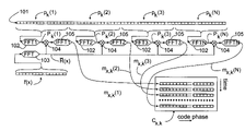
- the sample vector formation step is denoted with the reference number 101 in the appended FIG. 3 .
- the number of sample vectors is preferably N, where N is advantageously a power of two.
- the formation of sample vectors is repeated K times, as will be described later in this specification.
- the subscript k is used to denote different repetitions.
- the synchronization method according to the invention also comprises a correlation step in which a correlation function matrix is formed.
- the correlation step can be partly performed already during sampling, or after N sample vectors pk (l), p k ( 2 ) . . . p k (N) have been formed. If the correlation step is performed for example in such a way that a time-to-frequency transformation, such as a Fast Fourier Transform (FFT), is calculated for each sample vector after it has been saved, the same time-to-frequency transformer can be used for all N sample vectors p k (l), p k ( 2 ) . . . p k (N).
- FFT Fast Fourier Transform
- FIG. 3 shows the correlation step of the method, in which a correlation function matrix C x,k is formed from the sample vectors p k ( 1 ), p k ( 2 ) . . . p k (N).
- the Fourier transform is mainly used as an example of a time-to-frequency transformation throughout this description, and the inverse Fourier transform is used as an example of an inverse transformation, that is a frequency-to-time transformation, it is obvious that this invention is not limited to these examples only.
- a discrete Fourier transformation 102 is performed on each sample vector p k ( 1 ), p k ( 2 ) . . . p k (N).
- the reference codes r(x) corresponding to the C/A codes of all the satellites of the GPS system are stored in the receiver, where x refers to the satellite identifier and is, for example, in the range 1-36. It is not necessary to store the reference codes, but they can also be generated in the receiver.
- the reference code of the satellite transmitting the signal with which the receiver is being synchronized at a particular time is selected or generated.
- the reference code is temporally reversed.
- a discrete Fourier transformation 103 most preferably a fast Fourier transform (FFT) is performed on the reversed reference code, which is denoted by r (x) in FIG. 3 .
- R ( x ) FFT( r ( x )) (2)
- the reversed reference code r (x) and/or its FFT transform may have been saved in the memory means of the receiver in advance, or it is formed from the reference code r(x) in connection with the synchronization process.
- a multiplication 104 is performed between the Fourier transformation result P k (i) for each sample vector p k (i) and the Fourier transformation R (x) of the reversed reference code r (x).
- M x,k ( i ) R ( x ) ⁇ P k ( i ) (3)
- the cross-correlation result comprises 1023 elements.
- the cross-correlation results m x,k (i) formed from the various sample vectors p k (i) are used to form a correlation function matrix C x,k, in which the number of rows is the number N of sample vectors.
- the cross-correlation between the sample vectors p k (i) and the reference code r(x) by performing a Fourier transform (most suitably a fast Fourier transform FFT) on the sample vectors p k (i) and the reference code r(x) to form a Fourier transform P k (i) of the sample vector p k (i) and a Fourier transform R(x) of the reference code r(x), forming the complex conjugate P* k (i), of the Fourier transform P k (i) of the sample vector, multiplying the formed complex conjugate P* k (i) with the Fourier transform R(x) of the reference code and performing an inverse Fourier transform on the multiplication result.
- a Fourier transform most suitably a fast Fourier transform FFT
- a complex conjugate R*(x) can be formed from the Fourier transform R(x) of the reference code, in which case it is multiplied with the Fourier transformation P k (i) of the sample vector, whereafter an inverse Fourier transformation is performed on the multiplication result.
- the rows of the correlation function matrix C x,k formed in the correlation stage represent the cross-correlation of the received signal and the reference code with different phase differences at intervals of one millisecond.
- the correlation function matrix can be expressed as follows:
- the transpose 106 (FIG. 4 )of the correlation function matrix C x,k is used, in which the rows represent the signal samples in the time domain in the same manner as in a prior art correlator. Each row corresponds to a certain code phase difference between the received signal and the reference code.
- a Fourier transform 107 ( FIG. 4 ) is performed on each row of the transpose of the correlation function matrix C x,k to form a coherent search matrix A x,k , whereby a frequency analysis can be performed to determine the actual frequency shift. This is illustrated by FIG. 4 .
- a x , k FFT ⁇ ( C x , k T ) ( 7 )
- the correlation function matrix C x,k can also be formed e.g. by using matched filters, in a manner known as such.
- patent specification U.S. Pat. No. 5,373,531 discloses a correlator 25 implemented using matched filters ( FIG. 8 ), which can be adapted to form the correlation function matrix C x,k .
- the matched filter is formed from three shift registers so that the I-component of the received signal is fed to the first shift register 26 , the Q-component of the received signal is led to the second shift register 27 , and the reference code corresponding to the code of the satellite is fed to the third shift register 28 .
- the length of the shift registers 26 , 27 , 28 is preferably the same as the length of the sample vector, which is 1023 bits in the GPS system.
- the correlation is performed as follows. An exclusive NOR operation is performed between the bits of the shift register 26 containing the I-component and the bits of the shift register 28 containing the reference code in the first reference block 29 , and an exclusive NOR operation is performed between the bits of the shift register 27 containing the Q-component and the bits of the shift register 28 containing the reference code in the second reference block 30 .
- the result of the operation is bit-specific correlation information: if a bit of the received signal (examined in I and Q components) and a corresponding bit of the reference code match, the result is the binary value 1, and if not, the result is the binary value 0. If the signal correlates completely with the reference code, all the bits have the value 1. If none of the bits correlate, all the bits have the value 0.
- the values produced as the result of the correlation are summed in the first summing block 31 (I-values) and in the second summing block 32 (Q-values), whereby the result is a correlation value m x,k (i) having a certain code delay at a certain time. After one comparison, the reference code is shifted by one, after which a new correlation result is formed.
- Each correlation result formed according to the above-described method corresponds to one element of a row of the correlation function matrix C x,k (1023 in total). The steps mentioned above are repeated for each sample vector as required, whereby one row of the correlation function matrix C x,k is obtained at each iteration of the calculation.
- the signal is modulated with a signal of 50 bit/s, which in practical applications limits the value of the number N.
- the number N must be selected preferably so that the modulation does not have a substantial effect on the analysis.
- the optimum value of N is dependent on the window function used in the Fourier transformation. For example, if N is chosen to be equal to 32, the the noise band width is in the order of 30 Hz, which is still a little too large for detecting signals with a strength of the order of ⁇ 150 dBm at the receiver. For this reason, an optional non-coherent summing step, in which the signal-to-noise ratio is improved, is performed in the synchronization block 6 .
- the sample vector formation step, the correlation step and the analysis step described above are repeated 108 K times ( FIG. 5 ).
- the number of repetitions K is preferably selected such that the signal-to-noise ratio can be improved sufficiently, in a reasonable time.
- a coherent search matrix A x,k is formed each time the analysis step is performed, and a non-coherent summing operation is performed on it to form a non-coherent search matrix S x .
- the non-coherent search matrix S x is formed as follows.
- a magnitude value or some other absolute value, such as the square of the magnitude value is calculated for each of the complex elements a x,k (i,j) of each coherent search matrix A x,k .
- the numerical values calculated from corresponding elements of each non-coherent search matrix are summed, that is, an addition of the matrices is performed, which can be expressed with the formula:
- a non-coherent search matrix can be formed in at least two ways.
- the coherent search matrix formed at each iteration is stored. After the required number of repetition, a non-coherent search matrix is formed by summing the equivalent elements according to Formula 8.
- memory is required for storing the elements of all the coherent search matrices.
- one coherent search matrix is calculated initially, and the values of this matrix are copied as the elements of the non-coherent sum matrix.
- a coherent search matrix is formed, and the values of that matrix are summed with the corresponding elements of the non-coherent search matrix.
- summing of the equivalent elements is thus performed at each time of iteration. Only one coherent search matrix is thus stored, whereby less memory is needed than in the first alternative.
- the values of the elements s x (i,j) of the non-coherent search matrix S x are examined in the determination step, in an attempt to find 110 a value which exceeds the preceding threshold value and is clearly greater than the other values. If such a value like this is found, it represents the code phase difference and frequency deviation, because it is probably a signal transmitted by a satellite. If the signal is not transmitted by a satellite, but consists of noise or other incidental interference signals, no remarkable correlation peaks should arise.
- the code phase difference is apparent from the row index of the highest value, and correspondingly the frequency deviation is represented by the column index.
- 6 illustrates a situation in which a value, which is clearly larger than the other values, has been found. If, on the other hand, no such value is found in the non-coherent search matrix S x , that is, a signal transmitted by the searched for satellite was probably not received in the frequency range examined, the frequency range to be examined is changed, and the previously described steps are carried out to form a new non-coherent search matrix. By this method, the whole range of 6 kHz can be examined by repeating the steps described above as many times as is required.
- the previously described steps can be repeated for the whole frequency range to be examined, and the non-coherent search matrices formed for different iterations or only ranges containing possible peaks can be stored before searching for the largest correlation peak. In this way the possibility of false interpretation can be reduced for example in such a situation where the threshold value has been set too low and a spurious signal can cause a false interpretation.
- the frequency range would have to be scanned in ranges tens of Hertz in width, before even an attempt could be made to determine the phase and the frequency deviation.
- Tracking mode is set by changing the switches ( FIG. 1 ) to the second position, whereby received information is fed to code tracking block 11 , in which a feedback connection is also provided to enable fine adjustment of the frequency of the numerically controlled oscillator 5 .
- the receiver For calculating the location, the receiver performs the signal reception preferably on the basis of signals received from at least four satellites. In this case the previously described synchronization process is repeated as required on the basis of each satellite signal, whereupon the code of the satellite with which synchronization is performed is selected as the reference sequence r(x).
- a digital signal processor (not shown). Either hardware-based solutions or software implementations of the digital signal processor can be used to perform FFT transformations.
- a control element preferably a microprocessor or the like can be used to control the operation of the receiver.
- FIG. 7 An electronic device 24 according to a preferred embodiment of the invention, comprising a mobile station and a positioning receiver, is shown in FIG. 7 .
- a first antenna 13 is used for the reception of the signal transmitted by the positioning satellites.
- the received signal is applied to a first radio part 14 , in which the signal is down-converted and digitized.
- the first radio part comprises, among other things, the transformation block 2 , digitizing block 3 and multiplier block 4 of the receiver shown in FIG. 1 .
- the digitized signal which at this stage preferably comprises I and Q components, is applied to the digital signal processing unit 15 , in which, among other things, sample vectors are formed in the sample vector formation block 12 .
- the samples are saved in the first memory means 16 , which comprises, for example, a read/write memory and preferably also read only memory and/or non-volatile read/write memory for storing the program code of the digital signal processing unit 15 .
- the functions of the synchronization block 6 such as the formation of the correlation function matrix C x,k using, for example, Fourier transformers FFT 1 , FFT 2 , . . . , FFTN and/or matched filters are implemented in signal processing unit 15 .
- formation of the coherent search matrix A x,k and non-coherent summing step are also performed in the digital signal processing unit 15 .
- the digital signal processing unit 15 transmits information about the calculated phase difference and the frequency deviation to the processor block 17 , which comprises, for example, a microprocessor and I/O logic.
- the processor block 17 controls the scanning block 8 and the first switch 9 .
- the code tracking block 11 is at least partly implemented as program instructions of the processor block.
- the second memory means 18 is used as the data and program memory of the processor block 17 . It is obvious that the first memory means 16 and the second memory means 18 can also comprise common memory. Positioning information can be shown to the user on the display 19 .
- Operations of the mobile station are also implemented in the application software of the processor block 17 .
- the display 19 can be used to present telephone call information in a manner known as such.
- the user can control the positioning receiver and the mobile station using the keyboard 20 , t.
- the coding and decoding of audio signals is performed by means of a codec 21 .
- the radio part 22 and the second antenna 23 of the mobile station are also shown in FIG. 7 .
Landscapes
- Engineering & Computer Science (AREA)
- Computer Networks & Wireless Communication (AREA)
- Radar, Positioning & Navigation (AREA)
- Remote Sensing (AREA)
- Signal Processing (AREA)
- Physics & Mathematics (AREA)
- General Physics & Mathematics (AREA)
- Position Fixing By Use Of Radio Waves (AREA)
- Synchronisation In Digital Transmission Systems (AREA)
Applications Claiming Priority (2)
| Application Number | Priority Date | Filing Date | Title |
|---|---|---|---|
| FI19992653 | 1999-12-09 | ||
| FI992653A FI19992653A (fi) | 1999-12-09 | 1999-12-09 | Menetelmä vastaanottimen tahdistamiseksi ja vastaanotin |
Publications (2)
| Publication Number | Publication Date |
|---|---|
| US20010004381A1 US20010004381A1 (en) | 2001-06-21 |
| US7257153B2 true US7257153B2 (en) | 2007-08-14 |
Family
ID=8555730
Family Applications (1)
| Application Number | Title | Priority Date | Filing Date |
|---|---|---|---|
| US09/732,961 Expired - Lifetime US7257153B2 (en) | 1999-12-09 | 2000-12-08 | Method of synchronizing a receiver, and a receiver |
Country Status (6)
| Country | Link |
|---|---|
| US (1) | US7257153B2 (ko) |
| EP (1) | EP1107018A3 (ko) |
| JP (1) | JP2001237744A (ko) |
| KR (1) | KR20010062290A (ko) |
| CN (2) | CN1193516C (ko) |
| FI (1) | FI19992653A (ko) |
Cited By (4)
| Publication number | Priority date | Publication date | Assignee | Title |
|---|---|---|---|---|
| US20050163201A1 (en) * | 2004-01-28 | 2005-07-28 | Krasner Norman F. | Rapid acquisition methods and apparatus for GPS signals |
| US9081089B2 (en) | 2009-11-30 | 2015-07-14 | Furuno Electric Company Limited | Device, method and program for identifying unnecessary signal, GNSS receiving apparatus and mobile terminal |
| US10281584B2 (en) * | 2013-06-05 | 2019-05-07 | Airbus Defence And Space Limited | Receiver and method for direct sequence spread spectrum signals |
| US10574437B1 (en) | 2019-03-26 | 2020-02-25 | Honeywell International Inc. | Apparatus and method for synchronization of global navigation satellite system signal synchronization in a noisy environment |
Families Citing this family (20)
| Publication number | Priority date | Publication date | Assignee | Title |
|---|---|---|---|---|
| FI20000819A (fi) * | 2000-04-06 | 2002-01-25 | Nokia Mobile Phones Ltd | Menetelmä vastaanottimessa ja vastaanotin |
| JP3399923B2 (ja) | 2000-11-29 | 2003-04-28 | 松下電器産業株式会社 | 通信端末装置および通信端末装置における復号化方法 |
| JP2002247119A (ja) * | 2001-02-20 | 2002-08-30 | Advantest Corp | シンボル点推定装置、方法、プログラム、および該プログラムを記録した記録媒体ならびに変調解析装置 |
| FI110725B (fi) * | 2001-04-20 | 2003-03-14 | Nokia Corp | Menetelmä vastaanottimen tahdistamisessa ja vastaanotin |
| US7729412B2 (en) * | 2001-10-29 | 2010-06-01 | Qualcomm Incorporated | Parameter estimator with dynamically variable integration time |
| GB0130804D0 (en) | 2001-12-22 | 2002-02-06 | Koninkl Philips Electronics Nv | Method and apparatus for signal receipt and acquisition |
| FI113425B (fi) * | 2002-05-16 | 2004-04-15 | Nokia Corp | Menetelmä vastaanottimen tahdistamiseksi, järjestelmä ja elektroniikkalaite |
| EP1515453B1 (de) | 2003-09-09 | 2013-04-24 | u-blox AG | Verfahren zur Detektion eines Spreizspektrumsignals |
| US7395074B2 (en) * | 2004-04-08 | 2008-07-01 | Nokia Corporation | Position detection with frequency smoothing |
| US7421011B2 (en) * | 2004-05-27 | 2008-09-02 | Nokia Corporation | Performing an acquisition in a receiver |
| US7764726B2 (en) | 2004-12-01 | 2010-07-27 | Qualomm Incorporated | Systems, methods, and apparatus for jammer rejection |
| KR100778096B1 (ko) * | 2005-11-10 | 2007-11-22 | 재단법인서울대학교산학협력재단 | 확산 대역 신호를 이용하는 다중 접속 수신기의 신호 동기획득 방법 및 그 장치 |
| EP1992080A1 (en) * | 2006-03-02 | 2008-11-19 | QUALCOMM Incorporated | Method and apparatus for code space search in a receiver |
| US8279910B2 (en) | 2006-03-02 | 2012-10-02 | Qualcomm Incorporated | Method and apparatus for code space search in a receiver |
| EP2059908B1 (en) * | 2006-09-08 | 2014-11-12 | Cambridge Silicon Radio Limited | Processing of signals from global navigation satellite systems by a graphics processor |
| JP2008224683A (ja) * | 2008-05-15 | 2008-09-25 | Mazeran Systems Japan Kk | 衛星測位システム |
| US10044402B2 (en) * | 2010-06-25 | 2018-08-07 | Enmodus Limited | Timing synchronization for wired communications |
| WO2017175294A1 (ja) * | 2016-04-05 | 2017-10-12 | 三菱電機株式会社 | 信号受信装置及び信号受信方法 |
| CN112213751B (zh) * | 2020-10-15 | 2023-11-03 | 滁州学院 | 一种接收的随机跳时脉冲伪卫星信号中脉冲时延估计方法 |
| CN113238261B (zh) * | 2021-05-31 | 2022-12-13 | 西南电子技术研究所(中国电子科技集团公司第十研究所) | 低轨卫星扩频通信体制信号捕获跟踪系统 |
Citations (14)
| Publication number | Priority date | Publication date | Assignee | Title |
|---|---|---|---|---|
| WO1987001540A1 (en) | 1985-09-03 | 1987-03-12 | Motorola, Inc. | Apparatus for and method of doppler searching in a digital gps receiver |
| US4785463A (en) * | 1985-09-03 | 1988-11-15 | Motorola, Inc. | Digital global positioning system receiver |
| US5192957A (en) | 1991-07-01 | 1993-03-09 | Motorola, Inc. | Sequencer for a shared channel global positioning system receiver |
| US5373531A (en) | 1992-08-05 | 1994-12-13 | Pioneer Electronic Corporation | Signal acquisition and reception method for a global positioning system signal |
| WO1997014057A1 (en) | 1995-10-09 | 1997-04-17 | Snaptrack, Inc. | A gps receiver and method for processing gps signals |
| EP0809376A2 (en) | 1996-05-21 | 1997-11-26 | Nokia Mobile Phones Ltd. | Receiver synchronisation with timing and frequency error correction |
| US5812090A (en) | 1994-01-21 | 1998-09-22 | Thomson-Csf | Method and device enabling a modem to be synchronized with an RF digital data transmitter in the presence of jammers |
| FI102340B (fi) | 1997-01-16 | 1998-11-13 | Nokia Telecommunications Oy | Tiedonsiirtomenetelmä ja radiojärjestelmä |
| US6005889A (en) * | 1997-07-17 | 1999-12-21 | Nokia | Pseudo-random noise detector for signals having a carrier frequency offset |
| US6011812A (en) * | 1994-08-25 | 2000-01-04 | Nokia Telecommunications Oy | Receiving method and receiver |
| EP0971485A1 (en) | 1998-07-08 | 2000-01-12 | Siemens Aktiengesellschaft | Multiuser detection in CDMA using a correlation matrix |
| US6026130A (en) * | 1997-03-04 | 2000-02-15 | Advanced Micro Devices, Inc. | System and method for estimating a set of parameters for a transmission channel in a communication system |
| US6166690A (en) * | 1999-07-02 | 2000-12-26 | Sensor Systems, Inc. | Adaptive nulling methods for GPS reception in multiple-interference environments |
| US6462682B2 (en) * | 2000-03-27 | 2002-10-08 | Telefonaktiebolaget Lm Ericsson (Publ) | Sample rate conversion method and apparatus |
-
1999
- 1999-12-09 FI FI992653A patent/FI19992653A/fi not_active IP Right Cessation
-
2000
- 2000-12-07 EP EP00660222A patent/EP1107018A3/en not_active Withdrawn
- 2000-12-08 US US09/732,961 patent/US7257153B2/en not_active Expired - Lifetime
- 2000-12-09 CN CNB001372793A patent/CN1193516C/zh not_active Expired - Fee Related
- 2000-12-09 CN CNA2005100056686A patent/CN1642029A/zh active Pending
- 2000-12-09 KR KR1020000074889A patent/KR20010062290A/ko not_active Application Discontinuation
- 2000-12-11 JP JP2000375929A patent/JP2001237744A/ja active Pending
Patent Citations (14)
| Publication number | Priority date | Publication date | Assignee | Title |
|---|---|---|---|---|
| WO1987001540A1 (en) | 1985-09-03 | 1987-03-12 | Motorola, Inc. | Apparatus for and method of doppler searching in a digital gps receiver |
| US4785463A (en) * | 1985-09-03 | 1988-11-15 | Motorola, Inc. | Digital global positioning system receiver |
| US5192957A (en) | 1991-07-01 | 1993-03-09 | Motorola, Inc. | Sequencer for a shared channel global positioning system receiver |
| US5373531A (en) | 1992-08-05 | 1994-12-13 | Pioneer Electronic Corporation | Signal acquisition and reception method for a global positioning system signal |
| US5812090A (en) | 1994-01-21 | 1998-09-22 | Thomson-Csf | Method and device enabling a modem to be synchronized with an RF digital data transmitter in the presence of jammers |
| US6011812A (en) * | 1994-08-25 | 2000-01-04 | Nokia Telecommunications Oy | Receiving method and receiver |
| WO1997014057A1 (en) | 1995-10-09 | 1997-04-17 | Snaptrack, Inc. | A gps receiver and method for processing gps signals |
| EP0809376A2 (en) | 1996-05-21 | 1997-11-26 | Nokia Mobile Phones Ltd. | Receiver synchronisation with timing and frequency error correction |
| FI102340B (fi) | 1997-01-16 | 1998-11-13 | Nokia Telecommunications Oy | Tiedonsiirtomenetelmä ja radiojärjestelmä |
| US6026130A (en) * | 1997-03-04 | 2000-02-15 | Advanced Micro Devices, Inc. | System and method for estimating a set of parameters for a transmission channel in a communication system |
| US6005889A (en) * | 1997-07-17 | 1999-12-21 | Nokia | Pseudo-random noise detector for signals having a carrier frequency offset |
| EP0971485A1 (en) | 1998-07-08 | 2000-01-12 | Siemens Aktiengesellschaft | Multiuser detection in CDMA using a correlation matrix |
| US6166690A (en) * | 1999-07-02 | 2000-12-26 | Sensor Systems, Inc. | Adaptive nulling methods for GPS reception in multiple-interference environments |
| US6462682B2 (en) * | 2000-03-27 | 2002-10-08 | Telefonaktiebolaget Lm Ericsson (Publ) | Sample rate conversion method and apparatus |
Non-Patent Citations (4)
| Title |
|---|
| "Digital Signal Processing", Ifeachor et al., pp. 183-250, Sep. 2001. |
| "Direct-Sequence Spread Spectrum Acquisition Using Transform Domain Processing" Thomas A. Brown, Oct. 11, 1993, pp. 1018-1022. |
| "Improved Search Algorithm for Fast Acquisition in a DSP-based GPS Receiver" Flavio Daffara et al., Sep. 29, 1998, pp. 310-314. |
| Muramatsu and Kiya, Extended Overlap-Add and -Save Methods for Multirate Signal Processing,Sep. 1997,IEEE, vol. 45, p. 2376-2380. * |
Cited By (8)
| Publication number | Priority date | Publication date | Assignee | Title |
|---|---|---|---|---|
| US20050163201A1 (en) * | 2004-01-28 | 2005-07-28 | Krasner Norman F. | Rapid acquisition methods and apparatus for GPS signals |
| US7702002B2 (en) * | 2004-01-28 | 2010-04-20 | Qualcomm Incorporated | Rapid acquisition methods and apparatus for GPS signals |
| US20110103433A1 (en) * | 2004-01-28 | 2011-05-05 | Qualcomm Incorporated | Rapid acquisition methods and apparatus for gps signals |
| US8111736B2 (en) | 2004-01-28 | 2012-02-07 | Qualcomm Incorporated | Rapid acquisition methods and apparatus for GPS signals |
| US8576895B2 (en) | 2004-01-28 | 2013-11-05 | Qualcomm Incorporated | Rapid acquisition methods and apparatus for GPS signals |
| US9081089B2 (en) | 2009-11-30 | 2015-07-14 | Furuno Electric Company Limited | Device, method and program for identifying unnecessary signal, GNSS receiving apparatus and mobile terminal |
| US10281584B2 (en) * | 2013-06-05 | 2019-05-07 | Airbus Defence And Space Limited | Receiver and method for direct sequence spread spectrum signals |
| US10574437B1 (en) | 2019-03-26 | 2020-02-25 | Honeywell International Inc. | Apparatus and method for synchronization of global navigation satellite system signal synchronization in a noisy environment |
Also Published As
| Publication number | Publication date |
|---|---|
| FI19992653A (fi) | 2001-06-10 |
| CN1299195A (zh) | 2001-06-13 |
| EP1107018A3 (en) | 2003-09-17 |
| EP1107018A2 (en) | 2001-06-13 |
| CN1642029A (zh) | 2005-07-20 |
| JP2001237744A (ja) | 2001-08-31 |
| CN1193516C (zh) | 2005-03-16 |
| US20010004381A1 (en) | 2001-06-21 |
| KR20010062290A (ko) | 2001-07-07 |
Similar Documents
| Publication | Publication Date | Title |
|---|---|---|
| US7257153B2 (en) | Method of synchronizing a receiver, and a receiver | |
| US6909738B2 (en) | Method in a receiver and a receiver | |
| US6133873A (en) | Method and apparatus for adaptively processing GPS signals in a GPS receiver | |
| EP1712010B1 (en) | Rapid acquisition methods and apparatus for gps signals background | |
| US8005315B2 (en) | Spectrum spreading signal demodulation method and apparatus | |
| WO2005117282A1 (en) | Performing an acquisition in a receiver | |
| US6792035B2 (en) | Method and apparatus for reducing the effect of multipath propagation in a received signal | |
| KR100937130B1 (ko) | 히스토리 상관 데이터를 사용하여 신호 상관을 수행하기위한 방법 및 장치 | |
| EP1160582A2 (en) | Method and device for determining the phase of information, and its use in a positioning system | |
| EP1379010B1 (en) | A method, a system and an electronic device for synchronizing a receiver | |
| US7151793B2 (en) | Method for synchronizing a receiver, a positioning system, a receiver and an electronic device | |
| US7308021B2 (en) | Method in the synchronization of a receiver, and a receiver | |
| KR100854048B1 (ko) | 수신기에서 획득 수행 |
Legal Events
| Date | Code | Title | Description |
|---|---|---|---|
| AS | Assignment |
Owner name: NOKIA MOBILE PHONES, LTD., FINLAND Free format text: ASSIGNMENT OF ASSIGNORS INTEREST;ASSIGNOR:KONTOLA, ILKKA;REEL/FRAME:011350/0256 Effective date: 20001128 |
|
| STCF | Information on status: patent grant |
Free format text: PATENTED CASE |
|
| FEPP | Fee payment procedure |
Free format text: PAYOR NUMBER ASSIGNED (ORIGINAL EVENT CODE: ASPN); ENTITY STATUS OF PATENT OWNER: LARGE ENTITY |
|
| FPAY | Fee payment |
Year of fee payment: 4 |
|
| FPAY | Fee payment |
Year of fee payment: 8 |
|
| AS | Assignment |
Owner name: NOKIA TECHNOLOGIES OY, FINLAND Free format text: ASSIGNMENT OF ASSIGNORS INTEREST;ASSIGNOR:NOKIA CORPORATION;REEL/FRAME:036067/0222 Effective date: 20150116 |
|
| AS | Assignment |
Owner name: OMEGA CREDIT OPPORTUNITIES MASTER FUND, LP, NEW YORK Free format text: SECURITY INTEREST;ASSIGNOR:WSOU INVESTMENTS, LLC;REEL/FRAME:043966/0574 Effective date: 20170822 Owner name: OMEGA CREDIT OPPORTUNITIES MASTER FUND, LP, NEW YO Free format text: SECURITY INTEREST;ASSIGNOR:WSOU INVESTMENTS, LLC;REEL/FRAME:043966/0574 Effective date: 20170822 |
|
| AS | Assignment |
Owner name: WSOU INVESTMENTS, LLC, CALIFORNIA Free format text: ASSIGNMENT OF ASSIGNORS INTEREST;ASSIGNOR:NOKIA TECHNOLOGIES OY;REEL/FRAME:043953/0822 Effective date: 20170722 |
|
| FEPP | Fee payment procedure |
Free format text: MAINTENANCE FEE REMINDER MAILED (ORIGINAL EVENT CODE: REM.); ENTITY STATUS OF PATENT OWNER: LARGE ENTITY |
|
| AS | Assignment |
Owner name: BP FUNDING TRUST, SERIES SPL-VI, NEW YORK Free format text: SECURITY INTEREST;ASSIGNOR:WSOU INVESTMENTS, LLC;REEL/FRAME:049235/0068 Effective date: 20190516 |
|
| AS | Assignment |
Owner name: WSOU INVESTMENTS, LLC, CALIFORNIA Free format text: RELEASE BY SECURED PARTY;ASSIGNOR:OCO OPPORTUNITIES MASTER FUND, L.P. (F/K/A OMEGA CREDIT OPPORTUNITIES MASTER FUND LP;REEL/FRAME:049246/0405 Effective date: 20190516 |
|
| FEPP | Fee payment procedure |
Free format text: 11.5 YR SURCHARGE- LATE PMT W/IN 6 MO, LARGE ENTITY (ORIGINAL EVENT CODE: M1556); ENTITY STATUS OF PATENT OWNER: LARGE ENTITY |
|
| MAFP | Maintenance fee payment |
Free format text: PAYMENT OF MAINTENANCE FEE, 12TH YEAR, LARGE ENTITY (ORIGINAL EVENT CODE: M1553); ENTITY STATUS OF PATENT OWNER: LARGE ENTITY Year of fee payment: 12 |
|
| AS | Assignment |
Owner name: OT WSOU TERRIER HOLDINGS, LLC, CALIFORNIA Free format text: SECURITY INTEREST;ASSIGNOR:WSOU INVESTMENTS, LLC;REEL/FRAME:056990/0081 Effective date: 20210528 |
|
| AS | Assignment |
Owner name: WSOU INVESTMENTS, LLC, CALIFORNIA Free format text: RELEASE BY SECURED PARTY;ASSIGNOR:TERRIER SSC, LLC;REEL/FRAME:056526/0093 Effective date: 20210528 |