US7255830B2 - Method of making a three-dimensional sintered product - Google Patents
Method of making a three-dimensional sintered product Download PDFInfo
- Publication number
- US7255830B2 US7255830B2 US10/671,689 US67168903A US7255830B2 US 7255830 B2 US7255830 B2 US 7255830B2 US 67168903 A US67168903 A US 67168903A US 7255830 B2 US7255830 B2 US 7255830B2
- Authority
- US
- United States
- Prior art keywords
- layer
- powder material
- density
- higher density
- sintered
- Prior art date
- Legal status (The legal status is an assumption and is not a legal conclusion. Google has not performed a legal analysis and makes no representation as to the accuracy of the status listed.)
- Expired - Fee Related, expires
Links
- 238000004519 manufacturing process Methods 0.000 title description 10
- 239000000843 powder Substances 0.000 claims abstract description 106
- 239000000463 material Substances 0.000 claims abstract description 79
- 238000005245 sintering Methods 0.000 claims abstract description 46
- 238000000034 method Methods 0.000 claims abstract description 37
- 230000003287 optical effect Effects 0.000 claims abstract description 31
- PXHVJJICTQNCMI-UHFFFAOYSA-N Nickel Chemical compound [Ni] PXHVJJICTQNCMI-UHFFFAOYSA-N 0.000 claims description 6
- CWYNVVGOOAEACU-UHFFFAOYSA-N Fe2+ Chemical compound [Fe+2] CWYNVVGOOAEACU-UHFFFAOYSA-N 0.000 claims description 4
- 239000002184 metal Substances 0.000 claims description 4
- 229910052751 metal Inorganic materials 0.000 claims description 4
- 229910000881 Cu alloy Inorganic materials 0.000 claims description 3
- 229910052802 copper Inorganic materials 0.000 claims description 3
- 239000010949 copper Substances 0.000 claims description 3
- 230000007423 decrease Effects 0.000 claims description 3
- 229910052759 nickel Inorganic materials 0.000 claims description 3
- RYGMFSIKBFXOCR-UHFFFAOYSA-N Copper Chemical compound [Cu] RYGMFSIKBFXOCR-UHFFFAOYSA-N 0.000 claims description 2
- 229910000990 Ni alloy Inorganic materials 0.000 claims description 2
- 239000010410 layer Substances 0.000 description 205
- 239000011295 pitch Substances 0.000 description 11
- 238000005520 cutting process Methods 0.000 description 8
- 230000015572 biosynthetic process Effects 0.000 description 6
- 239000002344 surface layer Substances 0.000 description 5
- 230000001678 irradiating effect Effects 0.000 description 3
- 239000000203 mixture Substances 0.000 description 3
- 239000000853 adhesive Substances 0.000 description 2
- 230000001070 adhesive effect Effects 0.000 description 2
- 239000000498 cooling water Substances 0.000 description 2
- 238000007730 finishing process Methods 0.000 description 2
- 238000002844 melting Methods 0.000 description 2
- 230000008018 melting Effects 0.000 description 2
- 238000003801 milling Methods 0.000 description 2
- 238000012986 modification Methods 0.000 description 2
- 230000004048 modification Effects 0.000 description 2
- 238000000465 moulding Methods 0.000 description 2
- 238000000926 separation method Methods 0.000 description 2
- 238000007493 shaping process Methods 0.000 description 2
- 229910000640 Fe alloy Inorganic materials 0.000 description 1
- XEEYBQQBJWHFJM-UHFFFAOYSA-N Iron Chemical compound [Fe] XEEYBQQBJWHFJM-UHFFFAOYSA-N 0.000 description 1
- 235000010627 Phaseolus vulgaris Nutrition 0.000 description 1
- 244000046052 Phaseolus vulgaris Species 0.000 description 1
- 238000013459 approach Methods 0.000 description 1
- 238000000149 argon plasma sintering Methods 0.000 description 1
- 238000005422 blasting Methods 0.000 description 1
- 238000007664 blowing Methods 0.000 description 1
- 238000007796 conventional method Methods 0.000 description 1
- 238000005336 cracking Methods 0.000 description 1
- 238000013461 design Methods 0.000 description 1
- 238000005553 drilling Methods 0.000 description 1
- 238000001746 injection moulding Methods 0.000 description 1
- 229910010272 inorganic material Inorganic materials 0.000 description 1
- 239000011147 inorganic material Substances 0.000 description 1
- 238000003475 lamination Methods 0.000 description 1
- 238000003754 machining Methods 0.000 description 1
- 239000011368 organic material Substances 0.000 description 1
- 239000002245 particle Substances 0.000 description 1
- 230000001105 regulatory effect Effects 0.000 description 1
- 239000000523 sample Substances 0.000 description 1
- 238000007711 solidification Methods 0.000 description 1
- 230000008023 solidification Effects 0.000 description 1
- 238000013518 transcription Methods 0.000 description 1
- 230000035897 transcription Effects 0.000 description 1
- XLYOFNOQVPJJNP-UHFFFAOYSA-N water Substances O XLYOFNOQVPJJNP-UHFFFAOYSA-N 0.000 description 1
Images


Classifications
-
- B—PERFORMING OPERATIONS; TRANSPORTING
- B22—CASTING; POWDER METALLURGY
- B22F—WORKING METALLIC POWDER; MANUFACTURE OF ARTICLES FROM METALLIC POWDER; MAKING METALLIC POWDER; APPARATUS OR DEVICES SPECIALLY ADAPTED FOR METALLIC POWDER
- B22F3/00—Manufacture of workpieces or articles from metallic powder characterised by the manner of compacting or sintering; Apparatus specially adapted therefor ; Presses and furnaces
- B22F3/10—Sintering only
-
- B—PERFORMING OPERATIONS; TRANSPORTING
- B22—CASTING; POWDER METALLURGY
- B22F—WORKING METALLIC POWDER; MANUFACTURE OF ARTICLES FROM METALLIC POWDER; MAKING METALLIC POWDER; APPARATUS OR DEVICES SPECIALLY ADAPTED FOR METALLIC POWDER
- B22F3/00—Manufacture of workpieces or articles from metallic powder characterised by the manner of compacting or sintering; Apparatus specially adapted therefor ; Presses and furnaces
- B22F3/004—Filling molds with powder
-
- B—PERFORMING OPERATIONS; TRANSPORTING
- B22—CASTING; POWDER METALLURGY
- B22F—WORKING METALLIC POWDER; MANUFACTURE OF ARTICLES FROM METALLIC POWDER; MAKING METALLIC POWDER; APPARATUS OR DEVICES SPECIALLY ADAPTED FOR METALLIC POWDER
- B22F10/00—Additive manufacturing of workpieces or articles from metallic powder
- B22F10/20—Direct sintering or melting
- B22F10/28—Powder bed fusion, e.g. selective laser melting [SLM] or electron beam melting [EBM]
-
- B—PERFORMING OPERATIONS; TRANSPORTING
- B22—CASTING; POWDER METALLURGY
- B22F—WORKING METALLIC POWDER; MANUFACTURE OF ARTICLES FROM METALLIC POWDER; MAKING METALLIC POWDER; APPARATUS OR DEVICES SPECIALLY ADAPTED FOR METALLIC POWDER
- B22F10/00—Additive manufacturing of workpieces or articles from metallic powder
- B22F10/30—Process control
- B22F10/37—Process control of powder bed aspects, e.g. density
-
- B—PERFORMING OPERATIONS; TRANSPORTING
- B22—CASTING; POWDER METALLURGY
- B22F—WORKING METALLIC POWDER; MANUFACTURE OF ARTICLES FROM METALLIC POWDER; MAKING METALLIC POWDER; APPARATUS OR DEVICES SPECIALLY ADAPTED FOR METALLIC POWDER
- B22F10/00—Additive manufacturing of workpieces or articles from metallic powder
- B22F10/50—Treatment of workpieces or articles during build-up, e.g. treatments applied to fused layers during build-up
-
- B—PERFORMING OPERATIONS; TRANSPORTING
- B29—WORKING OF PLASTICS; WORKING OF SUBSTANCES IN A PLASTIC STATE IN GENERAL
- B29C—SHAPING OR JOINING OF PLASTICS; SHAPING OF MATERIAL IN A PLASTIC STATE, NOT OTHERWISE PROVIDED FOR; AFTER-TREATMENT OF THE SHAPED PRODUCTS, e.g. REPAIRING
- B29C64/00—Additive manufacturing, i.e. manufacturing of three-dimensional [3D] objects by additive deposition, additive agglomeration or additive layering, e.g. by 3D printing, stereolithography or selective laser sintering
- B29C64/10—Processes of additive manufacturing
- B29C64/141—Processes of additive manufacturing using only solid materials
- B29C64/153—Processes of additive manufacturing using only solid materials using layers of powder being selectively joined, e.g. by selective laser sintering or melting
-
- B—PERFORMING OPERATIONS; TRANSPORTING
- B33—ADDITIVE MANUFACTURING TECHNOLOGY
- B33Y—ADDITIVE MANUFACTURING, i.e. MANUFACTURING OF THREE-DIMENSIONAL [3-D] OBJECTS BY ADDITIVE DEPOSITION, ADDITIVE AGGLOMERATION OR ADDITIVE LAYERING, e.g. BY 3-D PRINTING, STEREOLITHOGRAPHY OR SELECTIVE LASER SINTERING
- B33Y10/00—Processes of additive manufacturing
-
- B—PERFORMING OPERATIONS; TRANSPORTING
- B22—CASTING; POWDER METALLURGY
- B22F—WORKING METALLIC POWDER; MANUFACTURE OF ARTICLES FROM METALLIC POWDER; MAKING METALLIC POWDER; APPARATUS OR DEVICES SPECIALLY ADAPTED FOR METALLIC POWDER
- B22F10/00—Additive manufacturing of workpieces or articles from metallic powder
- B22F10/30—Process control
- B22F10/36—Process control of energy beam parameters
- B22F10/366—Scanning parameters, e.g. hatch distance or scanning strategy
-
- B—PERFORMING OPERATIONS; TRANSPORTING
- B22—CASTING; POWDER METALLURGY
- B22F—WORKING METALLIC POWDER; MANUFACTURE OF ARTICLES FROM METALLIC POWDER; MAKING METALLIC POWDER; APPARATUS OR DEVICES SPECIALLY ADAPTED FOR METALLIC POWDER
- B22F12/00—Apparatus or devices specially adapted for additive manufacturing; Auxiliary means for additive manufacturing; Combinations of additive manufacturing apparatus or devices with other processing apparatus or devices
- B22F12/60—Planarisation devices; Compression devices
- B22F12/67—Blades
-
- B—PERFORMING OPERATIONS; TRANSPORTING
- B22—CASTING; POWDER METALLURGY
- B22F—WORKING METALLIC POWDER; MANUFACTURE OF ARTICLES FROM METALLIC POWDER; MAKING METALLIC POWDER; APPARATUS OR DEVICES SPECIALLY ADAPTED FOR METALLIC POWDER
- B22F12/00—Apparatus or devices specially adapted for additive manufacturing; Auxiliary means for additive manufacturing; Combinations of additive manufacturing apparatus or devices with other processing apparatus or devices
- B22F12/90—Means for process control, e.g. cameras or sensors
-
- B—PERFORMING OPERATIONS; TRANSPORTING
- B22—CASTING; POWDER METALLURGY
- B22F—WORKING METALLIC POWDER; MANUFACTURE OF ARTICLES FROM METALLIC POWDER; MAKING METALLIC POWDER; APPARATUS OR DEVICES SPECIALLY ADAPTED FOR METALLIC POWDER
- B22F2999/00—Aspects linked to processes or compositions used in powder metallurgy
-
- Y—GENERAL TAGGING OF NEW TECHNOLOGICAL DEVELOPMENTS; GENERAL TAGGING OF CROSS-SECTIONAL TECHNOLOGIES SPANNING OVER SEVERAL SECTIONS OF THE IPC; TECHNICAL SUBJECTS COVERED BY FORMER USPC CROSS-REFERENCE ART COLLECTIONS [XRACs] AND DIGESTS
- Y02—TECHNOLOGIES OR APPLICATIONS FOR MITIGATION OR ADAPTATION AGAINST CLIMATE CHANGE
- Y02P—CLIMATE CHANGE MITIGATION TECHNOLOGIES IN THE PRODUCTION OR PROCESSING OF GOODS
- Y02P10/00—Technologies related to metal processing
- Y02P10/25—Process efficiency
Definitions
- the present invention relates to a method of making a three-dimensional sintered product in which a target object is obtained by sintering and hardening powder material layers with an optical beam, especially relates to a method of preparing a metal mold by uniting a plurality of lamination made of metallic powder layers sintered by a laser beam.
- Japanese Patent No. 2620353 discloses a method of making a three-dimensional object known as photo-shaping.
- an optical beam L is first irradiated on a predetermined portion of a layer of powder material, which is either an organic material or an inorganic material, to form a sintered layer.
- the sintered layer thus obtained is then covered with a new layer of powder material, and the optical beam L is irradiated on a predetermined portion of the new layer to form a new sintered layer, which is united with the underlying layer.
- These steps are repeatedly carried out to form a sintered product or three-dimensional object in which a plurality of sintered layers are firmly laminated one above another.
- the irradiation of the optical beam L is conducted based on sectional form data of each of the layers that are obtained by slicing a model of design data (CAD data) of the three-dimensional object into a desired thickness.
- CAD data model of design data
- this method should be carried out by sintering necessary portions into a higher density and remaining portions into a lower density rather than by sintering all the portions into a same density.
- surface portions for transcription of object and piping portions for cooling water should be formed in a higher density and remaining portions should be formed in a lower density.
- the higher density sintered layers have a very smooth finished surface due to almost complete melting and solidification, thereby keeping water proof of cooling water piping.
- the layer of powder material having a density of 50 to 60% will be sintered to the higher density layer having a density of almost 100%, so that as shown in FIG. 16 , when the powder material layer 10 having a thickness of t 0 will be sintered into the higher density layer 11 H by an optical irradiation, the surface level of the higher density layer will be lowered by a difference [ ⁇ ] from the original surface level of the powder material layer.
- a thickness of the powder material layer is set to a value larger than a predetermined value [t] and furthermore, when the powder material layer 10 will be sintered by a sintering condition of higher density, the resulting surface of the higher density layer will be lowered by a stage difference [ ⁇ a] (difference [ ⁇ a] is larger than difference [ ⁇ ]).
- another powder material layer 10 is formed on the higher density layer 11 and sintered under a condition for the lower density to form a lower density layer 11 L. As shown in FIG. 18 , the powder material layer 10 becomes thicker by the above difference [ ⁇ a] in this case.
- the optical beam condition for lower density is determined according to a predetermined thickness [t] of the powder material layer 10 , the optical beam having a predetermined condition can not make the powder material thicker by difference [ ⁇ a] than a predetermined value [t] sintered completely, thereby not giving an enough adhesive power to the resulting lower density layer which is easy to be peeled from the higher density layer.
- the present invention has been developed to overcome the above-described disadvantages.
- Another objective of the present invention is to provide the method of the above-described type, which is not capable of preparing a three-dimensional sintered product provided with lower density layer completed sintered under a predetermined condition for the lower density layer.
- a method of preparing a three-dimensional sintered product which comprises steps of (a) sintering a predetermined portion of a first powder material layer by irradiation of an first optical beam to form a first layer having a higher density, (b) forming a second powder material layer on the first layer and (c) sintering a predetermined portion of the second powder material layer by irradiation of a second optical beam to form a second layer having a lower density and bond the second lower density layer to the first higher density layer and (d) repeating the steps (a) to (c) to form a three-dimensional sintered block comprising a plurality of the first and second layers,
- the second sintered layer having a low-density is formed on the first sintered layer having a high-density through an additional sintered layer having a middle density between the high-density of the first sintered layer and the low-density of the second sintered layer
- the second sintered layer having a lower density is not formed directly but through the additional layer having a middle density on the first sintered layer having a higher density, so that the bonding power between the higher density layer and the lower density layer does not become weaken due to a sequential change from the higher density to the lower density as well as no formation of the sintered layer having an insufficient lower density.
- the additional sintered layer having a middle density may comprise a plural of layers wherein the density of each layers decreases in proportion to distance from the higher density layer. Smooth change of density in the middle density layers can make a smooth change of characteristics from the higher density layer to the lower density layer.
- a suitable sintering condition should be determined according to a thickness of powder material layer to be sintered, so that the middle density layer can be formed in a suitable sintering condition.
- a method of preparing a three-dimensional sintered product comprising higher density layers and lower density layers sintered by irradiation of an optical beam on a predetermined portion of powder material layers, wherein a powder material layer for a lower density layer on at least the uppermost higher density layer is formed smaller in thickness than a usual predetermined value and is subjected to a sintering process according to a sintering condition of the lower density layer.
- powder material for the lower density layer is layered to have a suitable thickness for sintering. Therefore, if the higher density layer is formed smaller than a predetermined value, a next layer of powder material is always set to have a suitable thickness for a predetermined sintering condition so that the resulting lower density layer has a good adherence.
- a method of preparing a three-dimensional sintered product comprising higher density layers and lower density layers sintered by irradiation of an optical beam on a predetermined portion of powder material layers, wherein a layer of powder material for a higher density layer on at least the uppermost higher density layer is formed smaller in thickness than a usual predetermined value and is subjected to a sintering process according to a sintering condition of the lower density layer.
- an additional higher density layer is formed to adjust a forming position for the lower density layer even if a higher density layer is formed smaller than a predetermined value, so that a next layer of powder material for the low density layer is controlled to have a suitable thickness for sintering, thereby forming a lower density layer having a good adherence.
- a thickness of powder material layer may be determined by a sinking amount of a stage where a resulting layer is positioned and a next powder material layer is formed on the resulting layer.
- the additional higher density layer may be formed with no sinking amount of the stage. In this case, a time for operation of sinking the stage can be cut down.
- a thickness of the powder material layer and a sintering condition may be determined by a measuring result of product height already formed and/or driving load of blade for equalizing the powder material layer. According to this method, excess thickness of the powder material for lower density layer can be certainly avoided.
- a thickness of powder material for the lower density layer can be set to a predetermined value on the surface of the higher density layer which is positioned at a predetermined height, so that the powder material layer can be sintered by the optical beam having a suitable condition and then formation of a bad adherence lower density layer can be avoided.
- a thickness of a powder material for the lower density layer can be controlled to not larger than a predetermined value by existence of the middle density layer, control of thickness of powder material for the lower density layer and formation of additional higher density layer, so that formation of bad adhesive lower density layers and separation between the higher density layer and the lower density layer can be avoid.
- FIG. 1 is a schematic explanation view of a method of making a three-dimensional object according to a first embodiment of the present invention
- FIG. 2 is a schematic explanation view of a method of making a three-dimensional object according to a second embodiment of the present invention
- FIG. 3 is a schematic explanation view of a method of making a three-dimensional object according to a third embodiment of the present invention.
- FIG. 4 is a schematic explanation view of a method of making a three-dimensional object according to a fourth embodiment of the present invention.
- FIG. 5 is a schematic explanation view of a method of making a three-dimensional object according to a fifth embodiment of the present invention.
- FIGS. 6A and 6B are schematic explanation views to show a measuring step and a setting step of a layer of powder material for a lower density layer;
- FIGS. 7A and 7B are schematic explanation views to show a measuring step and a setting step of a layer of powder material for a higher density layer and FIG. 7C is a graph showing a driving load change of a blade for equalizing a layer of powder material;
- FIG. 8 is a schematic explanation view of a method of making a three-dimensional object according to a fifth embodiment of the present invention.
- FIG. 9 is a schematic explanation view of a method of making a three-dimensional object according to a sixth embodiment of the present invention.
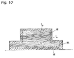
- FIG. 10 is a sectional view of a resulting sintered product made by the present invention method.
- FIG. 11 is schematic elevational views for showing steps of making a three-dimensional sintered product according to the present invention.
- FIG. 13 is a schematic perspective view of an apparatus for carrying out the present invention method
- FIG. 14 is a schematic elevational view of a model having a higher density region
- FIGS. 15A and 15B are vertical sectional view of a plurality of sintered layers as it is after made by the present invention and a plurality of sintered layers after a surface region thereof has been removed;
- FIGS. 16 to 18 are schematic elevational explanation views showing problems occurring in conventional methods
- the optical beam system for irradiating an optical beam is provided with control means for changing a scanning pitch and a scanning speed.
- a higher density sintered layer can be formed by a high sintering condition having a smaller scanning pitch and a slower scanning speed.
- a lower density sintered layer can be formed by a low scanning condition having a larger scanning pitch and a faster scanning speed.
- output of the optical beam may be changed according to a predetermined control schedule.
- the sintering table 20 is driven by a drive unit 5 so as to move up and down.
- the sintered layer-forming unit 3 forms the sintered layer 11 by irradiating a laser emitted from a laser beam generator 30 on the powder layer 10 via a scanning optical system including a deflector 31 and the like.
- a laser oscillator is preferably used as the laser beam generator 30 .
- the surface layer-removing unit 4 includes an XY drive Unit 40 mounted on a base thereof and a finishing machine 41 mounted on the XY drive unit 40 . It is preferred that the XY drive unit 40 be driven at a high speed using a linear motor.
- a galvanomirror is preferably used as the deflector 31 .
- a cutting machine such, for example, as an end mill or a drilling machine, a laser beam machine, or a blasting machine for carrying out plastic working with respect to an object by blowing sintered powder against it is preferably used as the finishing machine 41 .
- a polar coordinates drive unit may be used in place of the XY drive unit 40 .
- FIG. 11 depicts how to make a three-dimensional object using the apparatus referred to above.
- the organic or inorganic powder material is first supplied on a base 22 mounted on the sintering table 20 , which is employed as a distance regulator for regulating the distance between the sintered layer-forming unit 3 and a sintered layer.
- the powder material supplied on the base 22 is then leveled by the leveling blade 21 to form a first powder layer 10 , and an optical beam (laser beam) L is irradiated on a desired portion of the first powder layer 10 to sinter it, thereby forming a sintered layer 11 united with the base 22 .
- an optical beam (laser beam) L is irradiated on a desired portion of the first powder layer 10 to sinter it, thereby forming a sintered layer 11 united with the base 22 .
- the sintering table 20 is lowered by a predetermined length, and a second powder layer 10 is formed by supplying the powder material again and by leveling it using the leveling blade 21 .
- the optical beam L is again irradiated on a desired portion of the second powder layer 10 to sinter it, thereby forming another sintered layer 11 united with the underlying sintered layer 11 .
- the process of forming a new powder layer 10 after the sintering table 20 has been lowered and the process of irradiating the optical beam L on a desired portion of the new powder layer 10 to form a new sintered layer 11 are repeatedly carried out, thereby making the three-dimensional object.
- spherical iron powder particles having an average diameter of about 20 ⁇ m are preferably used for the powder material, and a CO 2 laser is preferably used as the optical beam.
- the preferred thickness ⁇ t 1 of each powder layer 10 is about 0.05 mm.
- FIG. 12 schematically depicts an example of a data flow according to the present invention.
- This data flow makes a desired three-dimensional CAD model have two kinds of data, data indicative of a path for laser irradiation and data indicative of a path for cutting. These paths are prepared from three-dimensional CAD data designed in advance to indicate the desired shape.
- the path for laser irradiation is substantially the same as that in the conventional shaping method, in which the target shape is defined by contour data for each section that has been obtained by slicing STL data, created from the three-dimensional CAD model, at equal pitches (0.05 mm in this embodiment).
- the contour data are added with laser irradiation conditions (the scanning speed, spot diameter, power and the like) to create new data, which are in turn delivered to the finishing process.
- the path for cutting is a path obtained in consideration of the diameter, kind, feed rate, speed of rotation etc. of the finishing tool to be used in the three-dimensional CAM.
- the data indicative of this path are also delivered to the finishing process.
- the data indicative of the path for laser irradiation are used in a laser sintering process, while the data indicative of the path for cutting are used in a high-speed cutting process. These two processes are repeatedly carried out to finish the target object.
- the irradiation of the optical beam be conducted so that at least the surface region of the three-dimensional object is sintered to have a high density (for example, a porosity less than 5%).
- a high density for example, a porosity less than 5%.
- reference numeral 12 denotes a high-density region
- reference numeral 16 denotes a low-density surface layer that has been created by the adhesion of the powder material, as discussed above.
- the inner portion located inside the high-density region 12 has a density lower than that of the high-density region 12 but higher than that of the low-density surface layer 16 .
- the surface layer-removing unit 4 is activated to cut the surface of the three-dimensional object that has been shaped by that time.
- a tool (ball end mill) of the milling head 41 having a diameter of 1 mm and an effective blade length of 3 mm can achieve cutting of a depth of 3 mm. Accordingly, if the thickness ⁇ t 1 of the powder layer 10 is 0.05 mm, the surface layer-removing unit 4 is activated when sixty sintered layers 11 have been formed.
- such surface layer-removing unit 4 can remove the low-density surface layer 16 created by the adhesion of the powder to the surface of the shaped object and can simultaneously cut out a portion of the high-density region 12 , thereby exposing the high-density region 12 over the entire surface of the shaped object, as shown in FIG. 15B .
- the shape of the sintered layers 11 is formed into a size slightly greater than that of a desired shape M.
- the horizontal size (width) of each sintered layer 11 comes to be about 0.3 mm greater than that of the desired shape M.
- the excess thickness in the vertical direction may be equal to or different from that in the horizontal direction.
- the vertical size of the shape of the sintered layers 11 is obtained by modifying the original data indicative of the vertical size of the desired shape M.
- the depth of cut, the feed rate, and the speed of rotation of the tool be set to 0.1–0.5 mm, 5–50 m/min, and 20,000–100,000 rpm, respectively.
- a high density sintering condition such as laser power 200 W, scanning pitch 0.2 mm, scanning speed 50 mm/sec.
- an intermediate layer 11 M was formed by the optical beam L under a medium density sintering condition such as laser power 200 W, scanning pitch 0.3 mm, scanning speed 100 mm/sec and then a lower density layer 11 L was formed by the optical beam under a low density sintering condition such as laser power 200 W, scanning pitch 0.5 mm, scanning speed 300 mm/sec.
- the medium density sintering condition is enough to give the layer of powder material having the larger thickness to be sintered completely, thereby separation between the medium density layer 11 M and the higher density layer 11 H being avoided.
- the medium intermediate layer may comprises a plurality of layers 11 Ma, 11 Mb and 11 Mc, sintering conditions for which decrease according to the distance to the lower density layer.
- the medium density layer 11 Ma closer to the higher density layer 11 H will be set to a sintering condition such as laser power 200 W, scanning pitch 0.3 mm, scanning speed 100 mm/sec and the medium density layer 11 Mb will be set to a sintering condition such as laser power 200 W, scanning pitch 0.35 mm, scanning speed 150 mm/sec while the medium density layer 11 Mc closer to the lower density layer 11 L will be set to a sintering condition such as laser power 200 W, scanning pitch 0.4 mm, scanning speed 200 mm/sec.
- the scanning speed may be controlled higher as the layers become closer to the lower density layer.
- the difference ⁇ a between the powder material layer and the higher density layer can be measured by a probe P for measuring height and also a thickness (t+ ⁇ a) of next powder material layers is measured and then according to the measuring result, a sintering condition for the medium density layers 11 M may be determined.
- a suitable condition for the medium density layer can be predetermined according to experimental data and so on.
- a sinking amount (including zero) of the stage 20 may be set to a smaller value than a predetermined value (t), thereby giving a next powder layer a suitable thickness for the lower density layer 11 L under the low density sintering condition.
- the next step can be selected from the following steps: a) a lower density layer 11 L is formed after formation of the additional higher density layer 11 H′ or b) a lower density layer 11 L is formed directly on the higher density layer 11 L without the additional layer 11 H′.
- a layer of powder material is formed without sinking of the stage 20 and the layer of powder material is sintered to a higher density layer 11 H′ to make the difference smaller.
- the stage 20 is lowered, the powder material is supplied and the lower density layer 11 L is formed.
- the difference ⁇ a can be measured by a driving load F of the blade 21 which is used for equalizing the powder material.
- a next powder material is formed without sinking of the stage 20 .
- a next powder material is formed with some sinking amount of the stage 20 .
- a large load of the blade 21 makes the current in driving motor larger according to the load while a small load makes the current smaller and approaches to a lowest driving value. Therefore, when the blade is passing on the sintered surface, normally the blade tends to receive a resistance due to roughness of the surface. However, if the blade is passing above the surface, the blade receives no load. Accordingly, as shown in FIG. 7C , the current value is monitored during constant moving and according to comparison between the current value thus obtained and a predetermined value it is necessary to determine whether the stage 20 should be lowered or not.
- a sinking amount of stage 20 should be changed from a predetermined value t (50 ⁇ m) to a smaller value ts (for example 20 ⁇ m) and a layer of powder material may be formed and sintered under a low density sintering condition to form the lower density layer 11 L.
- a higher density layer 11 H having a little bit larger than a predetermined value is formed and shaved off to a predetermined value and then a layer of powder material may be formed and sintered under a low density sintering condition to form the lower density layer 11 L.
- one sintered layer may include higher density portions and lower density portions.
- a sintered layer including a lower density portion is formed on another sintered layer including a higher density portion.
- M denotes a medium density portion.
- ferrous powder mixture such as mixture of ferrous powder of 50 weight % and non-ferrous powder selected from the group consisting nickel, nickel alloy, copper and copper alloy.
- the typical mixture comprises Cr—Mo—Fe alloy of 70 to 90 wt. %, P—Cu or Mn—Cu alloy of 5 to 30 Wt. % and Nickel of 0 to 10 wt. %.
- the average powder size is between 0.1 to 200 ⁇ m, preferably 1 to 100 ⁇ m, more preferably 5 to 50 ⁇ m.
- the present invention can be applied to organic powder material.
Landscapes
- Engineering & Computer Science (AREA)
- Manufacturing & Machinery (AREA)
- Chemical & Material Sciences (AREA)
- Materials Engineering (AREA)
- Physics & Mathematics (AREA)
- Mechanical Engineering (AREA)
- Optics & Photonics (AREA)
- Automation & Control Theory (AREA)
- Plasma & Fusion (AREA)
- Powder Metallurgy (AREA)
Abstract
Description
Claims (9)
Applications Claiming Priority (2)
| Application Number | Priority Date | Filing Date | Title |
|---|---|---|---|
| JPP2002-287768 | 2002-09-30 | ||
| JP2002287768 | 2002-09-30 |
Publications (2)
| Publication Number | Publication Date |
|---|---|
| US20040228754A1 US20040228754A1 (en) | 2004-11-18 |
| US7255830B2 true US7255830B2 (en) | 2007-08-14 |
Family
ID=32104949
Family Applications (1)
| Application Number | Title | Priority Date | Filing Date |
|---|---|---|---|
| US10/671,689 Expired - Fee Related US7255830B2 (en) | 2002-09-30 | 2003-09-29 | Method of making a three-dimensional sintered product |
Country Status (4)
| Country | Link |
|---|---|
| US (1) | US7255830B2 (en) |
| KR (1) | KR100553644B1 (en) |
| CN (1) | CN1233491C (en) |
| DE (1) | DE10344901B4 (en) |
Cited By (9)
| Publication number | Priority date | Publication date | Assignee | Title |
|---|---|---|---|---|
| US20080099936A1 (en) * | 2006-10-30 | 2008-05-01 | Matsuura Machinery Corporation | Optical Fabrication Method |
| US20090183790A1 (en) * | 2008-01-22 | 2009-07-23 | Moore Jason M | Direct metal laser sintered flow control element |
| US20100202914A1 (en) * | 2009-02-12 | 2010-08-12 | Matsuura Machinery Corporation | Method for Producing Three-Dimensional Shaped Article |
| US20140076749A1 (en) * | 2012-09-14 | 2014-03-20 | Raytheon Company | Variable density desiccator housing and method of manufacturing |
| US8738166B2 (en) | 2009-02-24 | 2014-05-27 | Panasonic Corporation | Method for manufacturing three-dimensional shaped object and three-dimensional shaped object obtained by the same |
| US9962632B2 (en) | 2015-04-28 | 2018-05-08 | Baker Hughes, A Ge Company, Llc | Inflow control device |
| US10022797B2 (en) | 2010-02-17 | 2018-07-17 | Panasonic Intellectual Property Management Co., Ltd. | Method for manufacturing three-dimensional shaped object and three-dimensional shaped object |
| US10898953B2 (en) | 2016-03-09 | 2021-01-26 | Panasonic Intellectual Property Management Co., Ltd. | Method for manufacturing three-dimensional shaped object |
| US12243085B1 (en) * | 2009-05-19 | 2025-03-04 | Cobra Golf Incorporated | Method and system for sales of golf equipment |
Families Citing this family (35)
| Publication number | Priority date | Publication date | Assignee | Title |
|---|---|---|---|---|
| DE102004009127A1 (en) * | 2004-02-25 | 2005-09-15 | Bego Medical Ag | Method and device for producing products by sintering and / or melting |
| JP3687677B1 (en) * | 2004-10-26 | 2005-08-24 | 松下電工株式会社 | Stereolithography method, stereolithography system, and stereolithography program |
| JP2006200030A (en) * | 2005-01-24 | 2006-08-03 | Aisan Ind Co Ltd | Manufacturing method and manufacturing apparatus for three-dimensional structure |
| JP4791745B2 (en) * | 2005-03-28 | 2011-10-12 | パナソニック電工株式会社 | Method of processing light incident / exit part of optical medium |
| US20070085241A1 (en) * | 2005-10-14 | 2007-04-19 | Northrop Grumman Corporation | High density performance process |
| DE102005050665A1 (en) * | 2005-10-20 | 2007-04-26 | Bego Medical Gmbh | Layer-wise production process with grain size influencing |
| JP4770838B2 (en) * | 2005-11-15 | 2011-09-14 | パナソニック電工株式会社 | Manufacturing method of three-dimensional shaped object |
| JP5213006B2 (en) * | 2006-12-22 | 2013-06-19 | パナソニック株式会社 | Manufacturing method of three-dimensional shaped object |
| JP4258567B1 (en) * | 2007-10-26 | 2009-04-30 | パナソニック電工株式会社 | Manufacturing method of three-dimensional shaped object |
| CA2715694A1 (en) | 2008-02-14 | 2009-08-20 | Nederlandse Organisatie Voor Toegepast-Natuurwetenschappelijk Onderzoek Tno | Method and system for layerwise production of a tangible object |
| JP4798185B2 (en) | 2008-08-05 | 2011-10-19 | パナソニック電工株式会社 | Additive manufacturing equipment |
| DE112010002686T5 (en) * | 2009-06-23 | 2013-01-03 | Panasonic Corporation | A method of manufacturing a three-dimensional molded article and a three-dimensional molded article produced by this method |
| CN103442830B (en) * | 2011-03-17 | 2015-09-09 | 松下电器产业株式会社 | The manufacture method of three dimensional structure and three dimensional structure |
| JP2015033717A (en) * | 2013-08-09 | 2015-02-19 | 三菱重工業株式会社 | Repair method |
| FR3014339B1 (en) * | 2013-12-06 | 2016-01-08 | Snecma | PROCESS FOR MANUFACTURING A PIECE BY SELECTIVE FUSION OF POWDER |
| US9707645B2 (en) * | 2014-01-09 | 2017-07-18 | General Electric Company | Systems, methods, and apparatus for locating and drilling closed holes of a turbine component |
| TWI601627B (en) * | 2014-03-17 | 2017-10-11 | 三緯國際立體列印科技股份有限公司 | Three-dimensional printing method, three-dimensional printing device and electronic device |
| US11285665B2 (en) * | 2014-03-31 | 2022-03-29 | Hewlett-Packard Development Company, L.P. | Generating three-dimensional objects |
| EP3126122B1 (en) * | 2014-03-31 | 2019-09-04 | Hewlett-Packard Development Company, L.P. | Generating three-dimensional objects |
| JP6503375B2 (en) | 2014-05-08 | 2019-04-17 | ストラタシス リミテッド | Method and apparatus for 3D printing by selective sintering |
| CN106182606A (en) * | 2015-04-10 | 2016-12-07 | 株式会社松浦机械制作所 | Resin injection molding mold |
| KR101726833B1 (en) * | 2015-10-28 | 2017-04-14 | 조선대학교산학협력단 | Rapid manufacturing process of ferrous and non-ferrous parts using plasma electron beam |
| CN105773072A (en) * | 2015-12-30 | 2016-07-20 | 北京航科精机科技有限公司 | Method for additive manufacturing of complex metal part through sheet layer overlaying |
| CN105710366B (en) * | 2016-03-03 | 2017-10-13 | 西安铂力特增材技术股份有限公司 | A kind of scan method for increasing material manufacturing three-dimensional body |
| KR102334945B1 (en) | 2016-04-11 | 2021-12-06 | 스트라타시스 엘티디. | Method and apparatus for additive manufacturing of powder materials |
| DE102016219968A1 (en) * | 2016-09-28 | 2018-03-29 | Eos Gmbh Electro Optical Systems | A method of determining a relative powder bed density in a device for generatively producing a three-dimensional object |
| JP2018095946A (en) * | 2016-12-16 | 2018-06-21 | キヤノン株式会社 | Manufacturing method of three-dimensional structure and three-dimensional modeling apparatus |
| JP6751040B2 (en) * | 2017-03-13 | 2020-09-02 | 株式会社神戸製鋼所 | Manufacturing method, manufacturing system, and manufacturing program for layered product |
| CN110494236B (en) | 2017-03-20 | 2022-07-26 | 斯特拉塔西斯公司 | Method and system for additive manufacturing of materials using powders |
| CN109317668B (en) * | 2017-07-31 | 2020-10-13 | 株式会社松浦机械制作所 | Three-dimensional modeling method |
| JP6976354B2 (en) | 2018-07-12 | 2021-12-08 | ヤマハ発動機株式会社 | Mold |
| DE112019007353T5 (en) * | 2019-05-23 | 2022-02-10 | Mitsubishi Heavy Industries Engine & Turbocharger, Ltd. | LAMINATED BODY MOLDING METHOD AND LAMINATED BODY MOLDING APPARATUS |
| CN111001803B (en) * | 2019-12-06 | 2022-04-26 | 深圳大学 | A kind of breathable mold with conformal cooling water channel and manufacturing method thereof |
| US11925981B2 (en) * | 2020-06-29 | 2024-03-12 | Arcam Ab | Method, apparatus and control unit for selectively sintering a powder layer in additive manufacturing processes to achieve a future, desired heat conductivity |
| CN115284187B (en) * | 2022-07-21 | 2024-06-21 | 湖南科技大学 | A method for rapidly preparing structured forming grinding wheels |
Citations (13)
| Publication number | Priority date | Publication date | Assignee | Title |
|---|---|---|---|---|
| WO1988002677A2 (en) | 1986-10-17 | 1988-04-21 | Board Of Regents, The University Of Texas System | Method and apparatus for producing parts by selective sintering |
| US4863538A (en) * | 1986-10-17 | 1989-09-05 | Board Of Regents, The University Of Texas System | Method and apparatus for producing parts by selective sintering |
| US4944817A (en) * | 1986-10-17 | 1990-07-31 | Board Of Regents, The University Of Texas System | Multiple material systems for selective beam sintering |
| US5182170A (en) * | 1989-09-05 | 1993-01-26 | Board Of Regents, The University Of Texas System | Method of producing parts by selective beam interaction of powder with gas phase reactant |
| US5385780A (en) * | 1990-12-05 | 1995-01-31 | The B. F. Goodrich Company | Sinterable mass of polymer powder having resistance to caking and method of preparing the mass |
| US5387380A (en) * | 1989-12-08 | 1995-02-07 | Massachusetts Institute Of Technology | Three-dimensional printing techniques |
| US5745834A (en) * | 1995-09-19 | 1998-04-28 | Rockwell International Corporation | Free form fabrication of metallic components |
| US5904890A (en) * | 1996-02-20 | 1999-05-18 | Eos Gmbh Electro Optical Systems | Apparatus and method for producing three-dimensional objects |
| US6066285A (en) * | 1997-12-12 | 2000-05-23 | University Of Florida | Solid freeform fabrication using power deposition |
| US6238614B1 (en) * | 1998-08-13 | 2001-05-29 | Korea Advanced Institute Science And Technology | Selective infiltration manufacturing method and apparatus to fabricate prototypes and moulds by infiltrating molten droplets selectively into layers of powder |
| JP2001254107A (en) | 2000-03-13 | 2001-09-18 | Oki Electric Ind Co Ltd | Three-dimensional model structure by stereolithography, object structure by stereolithography, and modeling method by stereolithography |
| US6657155B2 (en) * | 2000-10-05 | 2003-12-02 | Matsushita Electric Works, Ltd. | Method of and apparatus for making a three-dimensional object |
| US6767499B1 (en) * | 1998-02-19 | 2004-07-27 | Ecole Nationale Superieure De Ceramique Industrielle (Ensci) | Fast prototyping method by laser sintering of powder |
Family Cites Families (2)
| Publication number | Priority date | Publication date | Assignee | Title |
|---|---|---|---|---|
| JP3446733B2 (en) * | 2000-10-05 | 2003-09-16 | 松下電工株式会社 | Method and apparatus for manufacturing three-dimensional shaped object |
| JP3599056B2 (en) * | 2002-09-30 | 2004-12-08 | 松下電工株式会社 | Manufacturing method of three-dimensional shaped object |
-
2003
- 2003-09-26 DE DE10344901A patent/DE10344901B4/en not_active Expired - Fee Related
- 2003-09-29 KR KR1020030067314A patent/KR100553644B1/en not_active Expired - Fee Related
- 2003-09-29 CN CNB031595987A patent/CN1233491C/en not_active Expired - Fee Related
- 2003-09-29 US US10/671,689 patent/US7255830B2/en not_active Expired - Fee Related
Patent Citations (14)
| Publication number | Priority date | Publication date | Assignee | Title |
|---|---|---|---|---|
| JP2620353B2 (en) | 1986-10-17 | 1997-06-11 | ボード、オブ、リージェンツ、ザ、ユニバーシティー、オブ、テキサス、システム | Method of manufacturing parts by selective sintering |
| US4863538A (en) * | 1986-10-17 | 1989-09-05 | Board Of Regents, The University Of Texas System | Method and apparatus for producing parts by selective sintering |
| US4944817A (en) * | 1986-10-17 | 1990-07-31 | Board Of Regents, The University Of Texas System | Multiple material systems for selective beam sintering |
| WO1988002677A2 (en) | 1986-10-17 | 1988-04-21 | Board Of Regents, The University Of Texas System | Method and apparatus for producing parts by selective sintering |
| US5182170A (en) * | 1989-09-05 | 1993-01-26 | Board Of Regents, The University Of Texas System | Method of producing parts by selective beam interaction of powder with gas phase reactant |
| US5387380A (en) * | 1989-12-08 | 1995-02-07 | Massachusetts Institute Of Technology | Three-dimensional printing techniques |
| US5385780A (en) * | 1990-12-05 | 1995-01-31 | The B. F. Goodrich Company | Sinterable mass of polymer powder having resistance to caking and method of preparing the mass |
| US5745834A (en) * | 1995-09-19 | 1998-04-28 | Rockwell International Corporation | Free form fabrication of metallic components |
| US5904890A (en) * | 1996-02-20 | 1999-05-18 | Eos Gmbh Electro Optical Systems | Apparatus and method for producing three-dimensional objects |
| US6066285A (en) * | 1997-12-12 | 2000-05-23 | University Of Florida | Solid freeform fabrication using power deposition |
| US6767499B1 (en) * | 1998-02-19 | 2004-07-27 | Ecole Nationale Superieure De Ceramique Industrielle (Ensci) | Fast prototyping method by laser sintering of powder |
| US6238614B1 (en) * | 1998-08-13 | 2001-05-29 | Korea Advanced Institute Science And Technology | Selective infiltration manufacturing method and apparatus to fabricate prototypes and moulds by infiltrating molten droplets selectively into layers of powder |
| JP2001254107A (en) | 2000-03-13 | 2001-09-18 | Oki Electric Ind Co Ltd | Three-dimensional model structure by stereolithography, object structure by stereolithography, and modeling method by stereolithography |
| US6657155B2 (en) * | 2000-10-05 | 2003-12-02 | Matsushita Electric Works, Ltd. | Method of and apparatus for making a three-dimensional object |
Non-Patent Citations (4)
| Title |
|---|
| English language Abstract of JP 2001-254107, no date. |
| English language Abstract of JP 2001-254107. |
| English Language Abstract of JP 2620353, no date. |
| English Language Abstract of JP 2620353. |
Cited By (12)
| Publication number | Priority date | Publication date | Assignee | Title |
|---|---|---|---|---|
| US20080099936A1 (en) * | 2006-10-30 | 2008-05-01 | Matsuura Machinery Corporation | Optical Fabrication Method |
| US7941241B2 (en) * | 2006-10-30 | 2011-05-10 | Matsuura Machinery Corporation | Optical fabrication method |
| US20090183790A1 (en) * | 2008-01-22 | 2009-07-23 | Moore Jason M | Direct metal laser sintered flow control element |
| US8826938B2 (en) * | 2008-01-22 | 2014-09-09 | Control Components, Inc. | Direct metal laser sintered flow control element |
| US20100202914A1 (en) * | 2009-02-12 | 2010-08-12 | Matsuura Machinery Corporation | Method for Producing Three-Dimensional Shaped Article |
| US8083989B2 (en) * | 2009-02-12 | 2011-12-27 | Matsuura Machinery Corporation | Method for producing three-dimensional shaped article |
| US8738166B2 (en) | 2009-02-24 | 2014-05-27 | Panasonic Corporation | Method for manufacturing three-dimensional shaped object and three-dimensional shaped object obtained by the same |
| US12243085B1 (en) * | 2009-05-19 | 2025-03-04 | Cobra Golf Incorporated | Method and system for sales of golf equipment |
| US10022797B2 (en) | 2010-02-17 | 2018-07-17 | Panasonic Intellectual Property Management Co., Ltd. | Method for manufacturing three-dimensional shaped object and three-dimensional shaped object |
| US20140076749A1 (en) * | 2012-09-14 | 2014-03-20 | Raytheon Company | Variable density desiccator housing and method of manufacturing |
| US9962632B2 (en) | 2015-04-28 | 2018-05-08 | Baker Hughes, A Ge Company, Llc | Inflow control device |
| US10898953B2 (en) | 2016-03-09 | 2021-01-26 | Panasonic Intellectual Property Management Co., Ltd. | Method for manufacturing three-dimensional shaped object |
Also Published As
| Publication number | Publication date |
|---|---|
| DE10344901B4 (en) | 2006-09-07 |
| CN1233491C (en) | 2005-12-28 |
| KR20040028569A (en) | 2004-04-03 |
| US20040228754A1 (en) | 2004-11-18 |
| KR100553644B1 (en) | 2006-02-24 |
| CN1496769A (en) | 2004-05-19 |
| DE10344901A1 (en) | 2004-05-13 |
Similar Documents
| Publication | Publication Date | Title |
|---|---|---|
| US7255830B2 (en) | Method of making a three-dimensional sintered product | |
| US6657155B2 (en) | Method of and apparatus for making a three-dimensional object | |
| US7258720B2 (en) | Metal powder composition for use in selective laser sintering | |
| US8221850B2 (en) | Manufacturing method of three-dimensionally shaped object | |
| US9902113B2 (en) | Method for manufacturing three-dimensional shaped object and three-dimensional shaped object | |
| JP3446733B2 (en) | Method and apparatus for manufacturing three-dimensional shaped object | |
| KR101521481B1 (en) | Method for producing three-dimensionally shaped structure, and three-dimensionally shaped structure obtained by same | |
| US6209420B1 (en) | Method of manufacturing bits, bit components and other articles of manufacture | |
| KR101517652B1 (en) | Method for producing three-dimensional formed shapes, and three-dimensional formed shapes obtained thereby | |
| US7172724B2 (en) | Method of making sintered object | |
| JP4487636B2 (en) | Manufacturing method of three-dimensional shaped object | |
| US20100047470A1 (en) | Method for producing a three-dimensionally shaped object | |
| JP2008291318A (en) | Manufacturing method of three-dimensional shaped object | |
| JP4867790B2 (en) | Manufacturing method of three-dimensional shaped object | |
| KR20040028593A (en) | Method of manufacturing a three dimensional object | |
| JP2008291315A (en) | Manufacturing method of three-dimensional shaped object | |
| CN111545747B (en) | Method for additive manufacturing of a component with reduced build failure due to temperature variation | |
| TWI232786B (en) | Method of making a three-dimensional sintered product | |
| JP3687667B2 (en) | Metal powder for metal stereolithography | |
| JP3633607B2 (en) | Metal powder for metal stereolithography, method for producing the same, method for producing three-dimensional shaped article by metal stereolithography, and metal stereolithography | |
| CN116786842B (en) | 3D printing methods, control systems and equipment for controlling specific orientations of crystals | |
| JP2010065259A (en) | Method for producing three-dimensionally shaped object | |
| JP3433745B2 (en) | Manufacturing method and manufacturing apparatus for three-dimensional shaped object | |
| JP4640216B2 (en) | Metal powder for metal stereolithography | |
| JP2005059574A (en) | Manufacturing method of three-dimensional shaped object |
Legal Events
| Date | Code | Title | Description |
|---|---|---|---|
| AS | Assignment |
Owner name: MATSUSHITA ELECTRIC WORKS, LTD., JAPAN Free format text: ASSIGNMENT OF ASSIGNORS INTEREST;ASSIGNORS:ABE, SATOSHI;FUWA, ISAO;TOGEYAMA, HIROHIKO;AND OTHERS;REEL/FRAME:014766/0255;SIGNING DATES FROM 20030922 TO 20030924 |
|
| STCF | Information on status: patent grant |
Free format text: PATENTED CASE |
|
| FEPP | Fee payment procedure |
Free format text: PAYOR NUMBER ASSIGNED (ORIGINAL EVENT CODE: ASPN); ENTITY STATUS OF PATENT OWNER: LARGE ENTITY |
|
| AS | Assignment |
Owner name: PANASONIC ELECTRIC WORKS CO., LTD., JAPAN Free format text: CHANGE OF NAME;ASSIGNOR:MATSUSHITA ELECTRIC WORKS, LTD.;REEL/FRAME:022191/0478 Effective date: 20081001 Owner name: PANASONIC ELECTRIC WORKS CO., LTD.,JAPAN Free format text: CHANGE OF NAME;ASSIGNOR:MATSUSHITA ELECTRIC WORKS, LTD.;REEL/FRAME:022191/0478 Effective date: 20081001 |
|
| FPAY | Fee payment |
Year of fee payment: 4 |
|
| FEPP | Fee payment procedure |
Free format text: PAYOR NUMBER ASSIGNED (ORIGINAL EVENT CODE: ASPN); ENTITY STATUS OF PATENT OWNER: LARGE ENTITY |
|
| FPAY | Fee payment |
Year of fee payment: 8 |
|
| FEPP | Fee payment procedure |
Free format text: MAINTENANCE FEE REMINDER MAILED (ORIGINAL EVENT CODE: REM.); ENTITY STATUS OF PATENT OWNER: LARGE ENTITY |
|
| LAPS | Lapse for failure to pay maintenance fees |
Free format text: PATENT EXPIRED FOR FAILURE TO PAY MAINTENANCE FEES (ORIGINAL EVENT CODE: EXP.); ENTITY STATUS OF PATENT OWNER: LARGE ENTITY |
|
| STCH | Information on status: patent discontinuation |
Free format text: PATENT EXPIRED DUE TO NONPAYMENT OF MAINTENANCE FEES UNDER 37 CFR 1.362 |
|
| FP | Lapsed due to failure to pay maintenance fee |
Effective date: 20190814 |