US7240559B2 - Manometer - Google Patents
Manometer Download PDFInfo
- Publication number
- US7240559B2 US7240559B2 US11/210,469 US21046905A US7240559B2 US 7240559 B2 US7240559 B2 US 7240559B2 US 21046905 A US21046905 A US 21046905A US 7240559 B2 US7240559 B2 US 7240559B2
- Authority
- US
- United States
- Prior art keywords
- housing
- connecting piece
- manometer
- viewing glass
- pointer
- Prior art date
- Legal status (The legal status is an assumption and is not a legal conclusion. Google has not performed a legal analysis and makes no representation as to the accuracy of the status listed.)
- Expired - Fee Related
Links
Images


Classifications
-
- G—PHYSICS
- G01—MEASURING; TESTING
- G01L—MEASURING FORCE, STRESS, TORQUE, WORK, MECHANICAL POWER, MECHANICAL EFFICIENCY, OR FLUID PRESSURE
- G01L7/00—Measuring the steady or quasi-steady pressure of a fluid or a fluent solid material by mechanical or fluid pressure-sensitive elements
- G01L7/02—Measuring the steady or quasi-steady pressure of a fluid or a fluent solid material by mechanical or fluid pressure-sensitive elements in the form of elastically-deformable gauges
- G01L7/04—Measuring the steady or quasi-steady pressure of a fluid or a fluent solid material by mechanical or fluid pressure-sensitive elements in the form of elastically-deformable gauges in the form of flexible, deformable tubes, e.g. Bourdon gauges
Definitions
- the invention relates to a manometer.
- Such a manometer is known from DE 101 23 103 A1.
- This has a housing with a bourdon tube arranged therein, a connecting piece rigidly connected to the housing, a viewing glass arranged on the housing, and a pointer that can rotate at the bottom side of the viewing glass. The pointer is in engagement with the free end of the bourdon tube.
- the connecting piece of this known manometer has threads on its outer side.
- the manometer is fixed, e.g., in a fire extinguisher valve, by means of these threads.
- the screwing on and tightening of the manometer is typically realized by means of a hexagonal head, which is provided on the outer side of the connecting piece. By means of a commercially available wrench, the manometer can then be fixed by hand.
- this type of mounting has the disadvantage that automatic assembly is not possible without additional means.
- An object of the invention is the design of a manometer of the type named above, which can be easily and economically produced and which also enables simple automatic assembly.
- the manometer there are several cutouts for engaging an assembly tool placed over the periphery in the connecting piece of the housing, which is bent over or crimpled for attachment of the viewing glass.
- the connecting piece is connected to the housing with a positive fit. This arrangement enables assembly from the front or from above. A suitable assembly tool engages in the cutout, so that automatic assembly with a torque wrench or a similar tool is possible.
- the positive-fit connection is achieved by projections on the housing. These projections engage in a corresponding groove on the connecting piece.
- the cutouts in the connecting piece have diagonally inwardly converging side edges. Therefore, after the crimpling of the connecting piece, the cutouts have a rectangular cross section for right-angle engagement of an assembly tool.
- FIG. 1 a manometer in longitudinal section
- FIG. 2 the manometer shown in FIG. 1 in a plan view
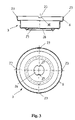
- FIG. 3 the housing of the manometer shown in FIG. 1 in longitudinal section and a plan view
- FIG. 4 the connecting piece of the manometer shown in FIG. 1 in longitudinal section and a plan view.
- the manometer shown in FIGS. 1 and 2 in longitudinal section and a plan view contains a bowl-shaped housing 1 , in which is arranged a spiral-shaped bent bourdon tube 2 with an open end 3 fixed to the housing and a freely movable closed end 4 .
- the housing 1 is covered on its top side by a circular viewing glass 5 .
- the housing 1 which is configured as a sheet-metal part, has on its top side a surrounding connecting piece 6 and an annular surface 7 for support of the viewing glass 5 .
- the connecting piece 6 is flanged inwards when the manometer is assembled and presses against the viewing glass 5 on an outer annular shoulder 8 , whereby this glass is held.
- a connecting piece 9 shown separately in FIG. 4 is attached on the bottom side of the housing 1 .
- the connecting piece 9 has on its outer side threads 10 for fixing the manometer in a bore of a component, e.g., a fire extinguisher, under pressure.
- a bore 11 connected to the open end 3 of the bourdon tube 2 is arranged in the connecting piece 9 .
- a filter 12 can be inserted in the bore 11 of the connecting piece 9 .
- the connecting piece 9 further contains on its outer side an annular groove 13 for a sealing ring 14 .
- a sealing flange 15 made from a suitable joining material for sealing is also affixed.
- the closed free end 4 of the bourdon tube 2 is angled and engages between two laterally flexible legs of a downwardly projecting connecting part 16 of a pointer 17 , which can rotate on a journal 19 offset laterally relative to the center axis 18 of the manometer.
- the journal 19 for the pointer 17 is formed integrally with the viewing glass 5 on the bottom side of this panel.
- a display or dial face 20 provided with a display scale is also set locked in rotation on the journal 19 .
- the pointer 17 is arranged so that it can rotate freely between the viewing glass 5 and the display or dial face 20 .
- the display or dial face 20 has a cutout 21 adapted to the turning range of the pointer 17 .
- the connecting part 16 of the pointer 17 extends through this cutout.
- An adhesive film 24 is applied in a center cutout 22 of the viewing glass 16 [sic; 5 ].
- the housing 1 formed as a sheet-metal part is shown in the not-yet assembled state.
- the surrounding connecting piece 6 projects directly upwards.
- Four cutouts 23 distributed uniformly over the periphery are provided in the connecting piece 6 .
- the cutouts 23 have slightly inclined side edges 30 .
- the side edges 30 converge diagonally inwardly, so that the cutouts 23 become narrower. Therefore, the cutouts 23 have a rectangular cross section following the flange on the connecting piece 6 and thus enable the right-angle engagement of an assembly tool.
- a center opening 26 for holding the connecting piece 9 is formed in the base 25 of the housing 1 .
- Two opposing projections 27 for engagement in a groove 31 that can be seen in FIG. 4 on the top side of the connecting piece 9 are provided on the opening 26 . In this way, a rotationally locked connection between the housing 1 and the connecting piece 9 is achieved.
- the groove 31 extends between two upwardly projecting annular segment-shaped connecting pieces 29 , which are flanged outwardly for connecting the connecting piece 9 to the housing 1 , as shown in FIG. 1 .
- the connecting piece 9 Underneath the connecting piece 29 , the connecting piece 9 has a hexagonal section 32 , under which the annular groove 13 for the sealing ring 14 is located. Beneath the annular groove 13 is a threaded section with external threads 10 .
- the housing 1 is set on the connecting piece 9 , so that the projections 27 engage in the groove 31 . Then the two connecting pieces 29 of the connecting piece 9 are crimped, whereby a fixed connection secured against twisting is produced between the housing 1 and the connecting piece 9 .
- the pointer 17 is set on the journal 19 projecting inwardly from the viewing glass 5 .
- this journal contains a pointer holding region, whose outer diameter is adapted to the inner diameter of a bore of the pointer 17 .
- the journal 19 also contains an end region with a smaller diameter, on which the display or dial face 20 is locked in rotation.
- the end region of the journal can be deformed, e.g., by means of a hot-welding or ultrasonic welding method, such that the display or dial face 20 is locked in rotation with the viewing glass 5 while maintaining the movability of the pointer 9 [sic; 17 ] by means of the journal 11 .
- the component produced in this way can then be inserted into the bowl-shaped housing 1 , so that the connecting part 16 of the pointer 17 overlaps the free end 4 of the bourdon tube 2 with its two legs. If the tip of the pointer 17 does not align with a zero marking on the display or dial face 20 , the component can be turned relative to the housing for the corresponding adjustment. After successful adjustment, the connecting piece 6 of the housing 1 is then crimped over the sight glass 5 .
Abstract
The invention relates to a manometer with a housing, a connecting piece rigidly connected to the housing, a bourdon tube arranged in the housing, a viewing glass fixed on the housing, and a pointer, which can rotate on the inside of the viewing glass and which is engaged with a free end of the bourdon tube, wherein the housing has on its top side a connecting piece that is bent inwardly for connecting to the viewing glass. To simplify the assembly, several cutouts distributed over the periphery are arranged in the connecting piece of the housing for engagement of an assembly tool, wherein the housing is connected to the connecting piece with a positive fit.
Description
The invention relates to a manometer.
Such a manometer is known from DE 101 23 103 A1. This has a housing with a bourdon tube arranged therein, a connecting piece rigidly connected to the housing, a viewing glass arranged on the housing, and a pointer that can rotate at the bottom side of the viewing glass. The pointer is in engagement with the free end of the bourdon tube. The connecting piece of this known manometer has threads on its outer side. The manometer is fixed, e.g., in a fire extinguisher valve, by means of these threads. The screwing on and tightening of the manometer is typically realized by means of a hexagonal head, which is provided on the outer side of the connecting piece. By means of a commercially available wrench, the manometer can then be fixed by hand. However, this type of mounting has the disadvantage that automatic assembly is not possible without additional means.
An object of the invention is the design of a manometer of the type named above, which can be easily and economically produced and which also enables simple automatic assembly.
This object is achieved by a manometer as set in the claims. Advantageous embodiments of the invention are also recited in the claims.
In the manometer according to the invention, there are several cutouts for engaging an assembly tool placed over the periphery in the connecting piece of the housing, which is bent over or crimpled for attachment of the viewing glass. In addition, the connecting piece is connected to the housing with a positive fit. This arrangement enables assembly from the front or from above. A suitable assembly tool engages in the cutout, so that automatic assembly with a torque wrench or a similar tool is possible.
In one configuration of the invention that is especially preferred in terms of production, the positive-fit connection is achieved by projections on the housing. These projections engage in a corresponding groove on the connecting piece.
In the not-yet assembled state of the housing, i.e., with a connecting piece that has not yet been crimped, the cutouts in the connecting piece have diagonally inwardly converging side edges. Therefore, after the crimpling of the connecting piece, the cutouts have a rectangular cross section for right-angle engagement of an assembly tool.
Additional details and advantages of the invention result from the following description of a preferred embodiment with reference to the drawing. Shown are:
The manometer shown in FIGS. 1 and 2 in longitudinal section and a plan view contains a bowl-shaped housing 1, in which is arranged a spiral-shaped bent bourdon tube 2 with an open end 3 fixed to the housing and a freely movable closed end 4. The housing 1 is covered on its top side by a circular viewing glass 5. For fixing the viewing glass 5 to the housing 1, the housing 1, which is configured as a sheet-metal part, has on its top side a surrounding connecting piece 6 and an annular surface 7 for support of the viewing glass 5. The connecting piece 6 is flanged inwards when the manometer is assembled and presses against the viewing glass 5 on an outer annular shoulder 8, whereby this glass is held. On the bottom side of the housing 1, a connecting piece 9 shown separately in FIG. 4 is attached. The connecting piece 9 has on its outer side threads 10 for fixing the manometer in a bore of a component, e.g., a fire extinguisher, under pressure. A bore 11 connected to the open end 3 of the bourdon tube 2 is arranged in the connecting piece 9. By means of this bore, the interior of the bourdon tube 2 can be charged with the pressure to be measured. A filter 12 can be inserted in the bore 11 of the connecting piece 9. The connecting piece 9 further contains on its outer side an annular groove 13 for a sealing ring 14. At the transition between the connecting piece 9 and the housing 1, a sealing flange 15 made from a suitable joining material for sealing is also affixed.
The closed free end 4 of the bourdon tube 2 is angled and engages between two laterally flexible legs of a downwardly projecting connecting part 16 of a pointer 17, which can rotate on a journal 19 offset laterally relative to the center axis 18 of the manometer. The journal 19 for the pointer 17 is formed integrally with the viewing glass 5 on the bottom side of this panel. A display or dial face 20 provided with a display scale is also set locked in rotation on the journal 19. The pointer 17 is arranged so that it can rotate freely between the viewing glass 5 and the display or dial face 20. The display or dial face 20 has a cutout 21 adapted to the turning range of the pointer 17. The connecting part 16 of the pointer 17 extends through this cutout. An adhesive film 24 is applied in a center cutout 22 of the viewing glass 16 [sic; 5].
In FIG. 3 , the housing 1 formed as a sheet-metal part is shown in the not-yet assembled state. In this state, the surrounding connecting piece 6 projects directly upwards. Four cutouts 23 distributed uniformly over the periphery are provided in the connecting piece 6. As follows from the top view of FIG. 2 , the cutouts 23 have slightly inclined side edges 30. The side edges 30 converge diagonally inwardly, so that the cutouts 23 become narrower. Therefore, the cutouts 23 have a rectangular cross section following the flange on the connecting piece 6 and thus enable the right-angle engagement of an assembly tool. A center opening 26 for holding the connecting piece 9 is formed in the base 25 of the housing 1. Two opposing projections 27 for engagement in a groove 31 that can be seen in FIG. 4 on the top side of the connecting piece 9 are provided on the opening 26. In this way, a rotationally locked connection between the housing 1 and the connecting piece 9 is achieved.
As follows from FIG. 4 , the groove 31 extends between two upwardly projecting annular segment-shaped connecting pieces 29, which are flanged outwardly for connecting the connecting piece 9 to the housing 1, as shown in FIG. 1 . Underneath the connecting piece 29, the connecting piece 9 has a hexagonal section 32, under which the annular groove 13 for the sealing ring 14 is located. Beneath the annular groove 13 is a threaded section with external threads 10.
To assemble the manometer, the housing 1 is set on the connecting piece 9, so that the projections 27 engage in the groove 31. Then the two connecting pieces 29 of the connecting piece 9 are crimped, whereby a fixed connection secured against twisting is produced between the housing 1 and the connecting piece 9. The pointer 17 is set on the journal 19 projecting inwardly from the viewing glass 5. For this purpose, this journal contains a pointer holding region, whose outer diameter is adapted to the inner diameter of a bore of the pointer 17. The journal 19 also contains an end region with a smaller diameter, on which the display or dial face 20 is locked in rotation. After the display or dial face 20 has been aligned, the end region of the journal can be deformed, e.g., by means of a hot-welding or ultrasonic welding method, such that the display or dial face 20 is locked in rotation with the viewing glass 5 while maintaining the movability of the pointer 9 [sic; 17] by means of the journal 11. The component produced in this way can then be inserted into the bowl-shaped housing 1, so that the connecting part 16 of the pointer 17 overlaps the free end 4 of the bourdon tube 2 with its two legs. If the tip of the pointer 17 does not align with a zero marking on the display or dial face 20, the component can be turned relative to the housing for the corresponding adjustment. After successful adjustment, the connecting piece 6 of the housing 1 is then crimped over the sight glass 5.
Claims (10)
1. In a manometer with a housing, a connecting piece rigidly connected to the housing, a bourdon tube arranged in the housing, a viewing glass fixed on the housing, and a pointer, which can rotate on the inside of the viewing glass and which engages with a free end of the bourdon tube, the improvement wherein:
the housing has on its top side an inwardly bent connecting piece for connecting to the viewing glass;
several cutouts distributed over the periphery are arranged in the connecting piece of the housing for engagement of an assembly tool;
the housing is connected to the connecting piece with a positive fit; and
the pointer is disposed on the inside of the viewing glass.
2. Manometer according to claim 1 , wherein the positive-fit connection between the housing and the connecting piece is realized by means of projections, which engage in a groove of the connecting piece.
3. Manometer according to claim 1 , wherein the connecting piece is connected to the housing by annular segment-shaped connecting pieces.
4. Manometer according to claim 1 , wherein the cutouts have diagonally inwardly converging side edges in the not-yet assembled state of the housing.
5. Manometer according to claim 1 , wherein the cutouts have a rectangular cross section in the assembled state of the hosing.
6. Manometer according to claim 1 , wherein the pointer can rotate on a journal formed on the interior of the viewing glass.
7. Manometer according to claim 6 , wherein a display or dial face is fixed on the journal.
8. Manometer according to claim 7 , wherein the display or dial face is welded or adhered to the journal.
9. Manometer according to claim 1 , wherein the connecting piece is rigidly connected to the housing by bent connecting pieces.
10. A manometer, comprising:
a housing having a top side with an inwardly bent connecting piece, said connecting piece having a periphery, being rigidly connected to said housing with a positive fit, and having several cutouts formed therein and distributed about said periphery for engagement with an assembly tool;
a bourdon tube disposed in said housing and having a free end;
a viewing glass having an inside and being fixed on said inwardly bent connecting piece; and
a pointer being rotatably disposed on said inside of said viewing glass and engaging said free end of the bourdon tube.
Applications Claiming Priority (2)
| Application Number | Priority Date | Filing Date | Title |
|---|---|---|---|
| DE102004051032.6 | 2004-10-20 | ||
| DE102004051032A DE102004051032B4 (en) | 2004-10-20 | 2004-10-20 | manometer |
Publications (2)
| Publication Number | Publication Date |
|---|---|
| US20060081060A1 US20060081060A1 (en) | 2006-04-20 |
| US7240559B2 true US7240559B2 (en) | 2007-07-10 |
Family
ID=36179346
Family Applications (1)
| Application Number | Title | Priority Date | Filing Date |
|---|---|---|---|
| US11/210,469 Expired - Fee Related US7240559B2 (en) | 2004-10-20 | 2005-08-24 | Manometer |
Country Status (2)
| Country | Link |
|---|---|
| US (1) | US7240559B2 (en) |
| DE (1) | DE102004051032B4 (en) |
Families Citing this family (23)
| Publication number | Priority date | Publication date | Assignee | Title |
|---|---|---|---|---|
| DE502007000825D1 (en) | 2006-12-05 | 2009-07-16 | Sata Gmbh & Co Kg | Ventilation for the gravity cup of a paint spray gun |
| WO2008103282A1 (en) | 2007-02-16 | 2008-08-28 | Nusbaum Michael J | Self-contained automatic fire extinguisher |
| ES2537617T3 (en) | 2008-03-12 | 2015-06-10 | Jeffrey D. Fox | Disposable spray gun cartridge |
| DE202008014389U1 (en) | 2008-10-29 | 2010-04-08 | Sata Gmbh & Co. Kg | Gravity cup for a paint spray gun |
| DE102009032399A1 (en) | 2009-07-08 | 2011-01-13 | Sata Gmbh & Co. Kg | Spray Gun |
| DE202010007355U1 (en) | 2010-05-28 | 2011-10-20 | Sata Gmbh & Co. Kg | Nozzle head for a spraying device |
| EP2646166B1 (en) | 2010-12-02 | 2018-11-07 | SATA GmbH & Co. KG | Spray gun and accessories |
| JP6189834B2 (en) | 2011-06-30 | 2017-08-30 | サタ ゲーエムベーハー アンド カンパニー カーゲー | Spray gun, spray medium guide unit and method for removal or removal |
| US8584528B2 (en) * | 2011-10-19 | 2013-11-19 | Chia-Hsin Lee | Manometer with a pressure transforming device |
| CA155474S (en) | 2013-09-27 | 2015-08-27 | Sata Gmbh & Co Kg | Spray gun |
| DE202013105779U1 (en) | 2013-12-18 | 2015-03-19 | Sata Gmbh & Co. Kg | Air nozzle termination for a paint spray gun |
| USD758537S1 (en) | 2014-07-31 | 2016-06-07 | Sata Gmbh & Co. Kg | Paint spray gun rear portion |
| CA159961S (en) | 2014-07-31 | 2015-07-17 | Sata Gmbh & Co Kg | Spray gun |
| CN105289870B (en) | 2014-07-31 | 2019-09-24 | 萨塔有限两合公司 | Manufacturing method, spray gun, gun body and the lid of spray gun |
| USD768820S1 (en) | 2014-09-03 | 2016-10-11 | Sata Gmbh & Co. Kg | Paint spray gun with pattern |
| DE102015002978B4 (en) | 2015-03-09 | 2020-10-15 | Festo Se & Co. Kg | manometer |
| DE102015006484A1 (en) | 2015-05-22 | 2016-11-24 | Sata Gmbh & Co. Kg | Nozzle arrangement for a spray gun, in particular paint spray gun and spray gun, in particular paint spray gun |
| DE102015016474A1 (en) | 2015-12-21 | 2017-06-22 | Sata Gmbh & Co. Kg | Air cap and nozzle assembly for a spray gun and spray gun |
| CN205995666U (en) | 2016-08-19 | 2017-03-08 | 萨塔有限两合公司 | Spray gun and its trigger |
| CN205966208U (en) | 2016-08-19 | 2017-02-22 | 萨塔有限两合公司 | Hood subassembly and spray gun |
| US11826771B2 (en) | 2018-08-01 | 2023-11-28 | Sata Gmbh & Co. Kg | Set of nozzles for a spray gun, spray gun system, method for embodying a nozzle module, method for selecting a nozzle module from a set of nozzles for a paint job, selection system and computer program product |
| DE102018118737A1 (en) | 2018-08-01 | 2020-02-06 | Sata Gmbh & Co. Kg | Nozzle for a spray gun, nozzle set for a spray gun, spray guns and method for producing a nozzle for a spray gun |
| DE102018118738A1 (en) | 2018-08-01 | 2020-02-06 | Sata Gmbh & Co. Kg | Base body for a spray gun, spray guns, spray gun set, method for producing a base body for a spray gun and method for converting a spray gun |
Citations (10)
| Publication number | Priority date | Publication date | Assignee | Title |
|---|---|---|---|---|
| US2803138A (en) * | 1953-09-08 | 1957-08-20 | Jas P Marsh Corp | Reinforced case for gauges |
| US3520192A (en) * | 1968-11-25 | 1970-07-14 | Marshalltown Mfg Inc | Pressure gauge casing with telescoping elements |
| US3630089A (en) | 1970-03-09 | 1971-12-28 | Dresser Ind | Pressure venting instrument casing assembly |
| DE7207104U (en) | 1972-02-25 | 1976-01-02 | Hochtief Ag Fuer Hoch- Und Tiefbauten Vorm. Gebr. Helfmann, 4300 Essen | DEVICE FOR DISTRIBUTING CONCRETE IN THE CONSTRUCTION OF BUILDINGS |
| DE7823994U1 (en) | 1978-08-11 | 1979-02-15 | Philipp Kachel Gmbh U. Co Kg, Armaturen- Und Thermometerfabrik, 8763 Klingenberg | HOUSING, EQUIPPED WITH A INSERT TUBE, FOR THERMAL MEASURING DEVICES, IN PARTICULAR BIMETAL THERMOMETERS |
| DE8331077U1 (en) | 1983-10-28 | 1984-03-29 | Alexander Wiegand Gmbh U. Co Armaturen- U. Manometerfabrik, 8763 Klingenberg | MANOMETER WITH A FUNCTION CHECKING DEVICE |
| DE8705784U1 (en) | 1986-04-21 | 1987-07-02 | Alexander Wiegand Gmbh U. Co Armaturen- U. Manometerfabrik, 8763 Klingenberg, De | |
| DE29812768U1 (en) | 1998-07-17 | 1999-11-25 | Ft Manovia Gmbh Druckmestechni | manometer |
| US6044712A (en) * | 1995-11-23 | 2000-04-04 | L'air Liquide, Societe Anonyme Pour L'etude Et L'exploitation Des Procedes George Claude | Bourdon-tube pressure gauge |
| DE10123103A1 (en) | 2001-05-12 | 2002-11-21 | Steffen Foerster | Bourdon tube type miniature manometer or pressure gauge has a fork shaped union between the free end of the Bourdon tube and the indicator, which acts to eliminate play in all positions of the indicator |
Family Cites Families (1)
| Publication number | Priority date | Publication date | Assignee | Title |
|---|---|---|---|---|
| DE7207148U (en) * | 1972-08-03 | Wiegand A Armaturen U.Manometerfabrik | Miniature manometer |
-
2004
- 2004-10-20 DE DE102004051032A patent/DE102004051032B4/en not_active Expired - Fee Related
-
2005
- 2005-08-24 US US11/210,469 patent/US7240559B2/en not_active Expired - Fee Related
Patent Citations (10)
| Publication number | Priority date | Publication date | Assignee | Title |
|---|---|---|---|---|
| US2803138A (en) * | 1953-09-08 | 1957-08-20 | Jas P Marsh Corp | Reinforced case for gauges |
| US3520192A (en) * | 1968-11-25 | 1970-07-14 | Marshalltown Mfg Inc | Pressure gauge casing with telescoping elements |
| US3630089A (en) | 1970-03-09 | 1971-12-28 | Dresser Ind | Pressure venting instrument casing assembly |
| DE7207104U (en) | 1972-02-25 | 1976-01-02 | Hochtief Ag Fuer Hoch- Und Tiefbauten Vorm. Gebr. Helfmann, 4300 Essen | DEVICE FOR DISTRIBUTING CONCRETE IN THE CONSTRUCTION OF BUILDINGS |
| DE7823994U1 (en) | 1978-08-11 | 1979-02-15 | Philipp Kachel Gmbh U. Co Kg, Armaturen- Und Thermometerfabrik, 8763 Klingenberg | HOUSING, EQUIPPED WITH A INSERT TUBE, FOR THERMAL MEASURING DEVICES, IN PARTICULAR BIMETAL THERMOMETERS |
| DE8331077U1 (en) | 1983-10-28 | 1984-03-29 | Alexander Wiegand Gmbh U. Co Armaturen- U. Manometerfabrik, 8763 Klingenberg | MANOMETER WITH A FUNCTION CHECKING DEVICE |
| DE8705784U1 (en) | 1986-04-21 | 1987-07-02 | Alexander Wiegand Gmbh U. Co Armaturen- U. Manometerfabrik, 8763 Klingenberg, De | |
| US6044712A (en) * | 1995-11-23 | 2000-04-04 | L'air Liquide, Societe Anonyme Pour L'etude Et L'exploitation Des Procedes George Claude | Bourdon-tube pressure gauge |
| DE29812768U1 (en) | 1998-07-17 | 1999-11-25 | Ft Manovia Gmbh Druckmestechni | manometer |
| DE10123103A1 (en) | 2001-05-12 | 2002-11-21 | Steffen Foerster | Bourdon tube type miniature manometer or pressure gauge has a fork shaped union between the free end of the Bourdon tube and the indicator, which acts to eliminate play in all positions of the indicator |
Also Published As
| Publication number | Publication date |
|---|---|
| DE102004051032B4 (en) | 2008-02-21 |
| DE102004051032A1 (en) | 2006-05-04 |
| US20060081060A1 (en) | 2006-04-20 |
Similar Documents
| Publication | Publication Date | Title |
|---|---|---|
| US7240559B2 (en) | Manometer | |
| US7976214B2 (en) | Portable watch | |
| US6105437A (en) | Pressure transducer | |
| US7128345B2 (en) | Terminal connection comprising a threaded sleeve, a counter-sleeve and a terminal insert | |
| US6851308B2 (en) | Device for fixing a pressure sensor intended to be mounted in a tire | |
| US4815053A (en) | Rotating-bezel watch | |
| CN104696583B (en) | control head | |
| JP6591635B2 (en) | Push button device for clock | |
| US20080257253A1 (en) | Rotary Gauge Structure | |
| US20050000296A1 (en) | Fastening arrangement for a sensor at a receptacle | |
| EP1338444A1 (en) | Combination of a valve and a pressure measurement device for a tyre | |
| CN102341684A (en) | Pressure Gage with Magnetically Coupled Diaphragm | |
| CH641666A5 (en) | Servo electric micro manipulator for the movement on ball coordinates. | |
| JP2004068953A (en) | Seal structure of valve and valve mounting part | |
| US6974248B2 (en) | Crown for watches and a tool for attaching a screw-in tube for the crown arrangement on a watch case | |
| EP1251310A1 (en) | Gas cooking appliance | |
| US7895897B2 (en) | Sensor assembly and use of a sensor assembly | |
| CN210291130U (en) | Mounting structure and air conditioner of disk seat and pipe fitting | |
| EP1441273A1 (en) | Pressure regulator with pressure gauge, particularly for LPG tanks | |
| CN115571489B (en) | Weight-increasing bottle cap, bottle using same and assembling process of bottle cap | |
| US7134697B2 (en) | 360° rotatable inlet screw assembly for a pneumatic tool | |
| JP3003704U (en) | Weight | |
| US20030031094A1 (en) | Clock and frame assembly and clock structure for use therewith | |
| CN210726888U (en) | Watch and riveting positioning rotating shaft connecting structure thereof | |
| JPH0862079A (en) | Mounting device of pressure sensor |
Legal Events
| Date | Code | Title | Description |
|---|---|---|---|
| FPAY | Fee payment |
Year of fee payment: 4 |
|
| REMI | Maintenance fee reminder mailed | ||
| LAPS | Lapse for failure to pay maintenance fees | ||
| STCH | Information on status: patent discontinuation |
Free format text: PATENT EXPIRED DUE TO NONPAYMENT OF MAINTENANCE FEES UNDER 37 CFR 1.362 |
|
| FP | Expired due to failure to pay maintenance fee |
Effective date: 20150710 |