US7239133B1 - Methods and systems for controlling the temperature stability of an inductor - Google Patents
Methods and systems for controlling the temperature stability of an inductor Download PDFInfo
- Publication number
- US7239133B1 US7239133B1 US11/335,201 US33520106A US7239133B1 US 7239133 B1 US7239133 B1 US 7239133B1 US 33520106 A US33520106 A US 33520106A US 7239133 B1 US7239133 B1 US 7239133B1
- Authority
- US
- United States
- Prior art keywords
- coil
- probe
- approximately
- accordance
- proximity probe
- Prior art date
- Legal status (The legal status is an assumption and is not a legal conclusion. Google has not performed a legal analysis and makes no representation as to the accuracy of the status listed.)
- Active, expires
Links
- 238000000034 method Methods 0.000 title claims abstract description 19
- 239000000523 sample Substances 0.000 claims abstract description 92
- 230000005284 excitation Effects 0.000 claims abstract description 16
- 230000001419 dependent effect Effects 0.000 claims description 8
- 230000000694 effects Effects 0.000 claims description 6
- 238000012544 monitoring process Methods 0.000 description 11
- 239000004020 conductor Substances 0.000 description 6
- 239000000463 material Substances 0.000 description 6
- 238000005259 measurement Methods 0.000 description 5
- 230000010355 oscillation Effects 0.000 description 4
- 238000005538 encapsulation Methods 0.000 description 3
- 238000010521 absorption reaction Methods 0.000 description 2
- 230000007613 environmental effect Effects 0.000 description 2
- 239000012212 insulator Substances 0.000 description 2
- 230000001681 protective effect Effects 0.000 description 2
- 238000012360 testing method Methods 0.000 description 2
- 238000004804 winding Methods 0.000 description 2
- 239000012467 final product Substances 0.000 description 1
- 238000004519 manufacturing process Methods 0.000 description 1
- 239000000203 mixture Substances 0.000 description 1
- 238000012986 modification Methods 0.000 description 1
- 230000004048 modification Effects 0.000 description 1
- 238000005096 rolling process Methods 0.000 description 1
- 238000007789 sealing Methods 0.000 description 1
- 229910001220 stainless steel Inorganic materials 0.000 description 1
- 239000010935 stainless steel Substances 0.000 description 1
Images


Classifications
-
- G—PHYSICS
- G01—MEASURING; TESTING
- G01R—MEASURING ELECTRIC VARIABLES; MEASURING MAGNETIC VARIABLES
- G01R1/00—Details of instruments or arrangements of the types included in groups G01R5/00 - G01R13/00 and G01R31/00
- G01R1/02—General constructional details
- G01R1/06—Measuring leads; Measuring probes
-
- G—PHYSICS
- G01—MEASURING; TESTING
- G01B—MEASURING LENGTH, THICKNESS OR SIMILAR LINEAR DIMENSIONS; MEASURING ANGLES; MEASURING AREAS; MEASURING IRREGULARITIES OF SURFACES OR CONTOURS
- G01B7/00—Measuring arrangements characterised by the use of electric or magnetic techniques
- G01B7/02—Measuring arrangements characterised by the use of electric or magnetic techniques for measuring length, width or thickness
- G01B7/023—Measuring arrangements characterised by the use of electric or magnetic techniques for measuring length, width or thickness for measuring distance between sensor and object
-
- H—ELECTRICITY
- H03—ELECTRONIC CIRCUITRY
- H03K—PULSE TECHNIQUE
- H03K17/00—Electronic switching or gating, i.e. not by contact-making and –breaking
- H03K17/94—Electronic switching or gating, i.e. not by contact-making and –breaking characterised by the way in which the control signals are generated
- H03K17/945—Proximity switches
- H03K17/95—Proximity switches using a magnetic detector
- H03K17/9502—Measures for increasing reliability
-
- H—ELECTRICITY
- H03—ELECTRONIC CIRCUITRY
- H03K—PULSE TECHNIQUE
- H03K17/00—Electronic switching or gating, i.e. not by contact-making and –breaking
- H03K17/94—Electronic switching or gating, i.e. not by contact-making and –breaking characterised by the way in which the control signals are generated
- H03K17/945—Proximity switches
- H03K17/95—Proximity switches using a magnetic detector
- H03K17/9505—Constructional details
Definitions
- This invention relates generally to controlling the temperature stability of an inductor, and more particularly to methods and apparatus for controlling the temperature stability of a sensing coil of a proximity probe.
- At least some known rotating and reciprocating machinery use an eddy current or proximity probe to facilitate monitoring machine vibration or rotor position characteristics.
- the environment that the proximity probe operates may be relatively harsh.
- the proximity probe outputs a signal correlative to a spacing between a target object such as, a rotating shaft of a machine or an outer ring of a rolling element bearing and a sensing coil of the proximity probe.
- a target object such as, a rotating shaft of a machine or an outer ring of a rolling element bearing and a sensing coil of the proximity probe.
- the gap or spacing between the target and the sensing coil of the proximity probe needs to remain within the linear range of the proximity probe for providing accurate and reliable measurements of machine vibration characteristics. Accordingly, to provide accurate and reliable measurement, a proximity probe should remain in the linear range of operation under all operating environmental conditions.
- the electronics associated with the proximity probe typically incorporates an oscillation circuit whose amplitude of oscillations is dependent on the conductance of the sensing coil.
- the sensing coil When the circuit is oscillating, the sensing coil has an alternating current flowing therein which causes the sensing coil to radiate energy in the form of an alternating magnetic field.
- the target object absorbs some of the radiated energy from the sensing coil when it is placed within the alternating field emanating from the sensing coil. This absorption of energy is a result of the alternating field generating eddy currents in the object which circulate so as to oppose the alternating field which created them.
- the amount of energy absorbed by the target object is correlative to the spacing between the target object and the sensing coil.
- the amplitude of oscillations of the oscillation circuit will vary as a function of spacing between the sensing coil and the target.
- the ability to provide accurate and reliable measurements over a wide range of circuit and environmental conditions is dependent, at least partially on, the characteristics of the sensing coil including the material and diameter of the wire used to wind the coil, the operating frequency of the system and the electronics of the proximity probe system.
- the sensing coil and the remaining electronics usually have a wide range of tolerances, such as gain, bias voltage, bias current and temperature coefficients. Accordingly, each production unit has to be initially calibrated to incorporate those tolerances.
- the sensing coil of the proximity probe usually contains sources of temperature drift error which are attempted to be compensated for in the final product.
- a source of the temperature drift error in the sensing coil is due to a temperature dependent resistance of the coil and an inductance of the coil.
- This temperature dependent resistance and inductance of the sensing coil effects a source of temperature drift error resulting in inaccurate proximity probe measurements as a consequence of the false appearance of a gap change between the target and sensing coil.
- Such inconsistencies in temperature stability of the proximity probe result in unpredictable and unreliable measurements even when the proximity probe is functioning in its linear range of operation. Compensation for such inconsistencies is usually only partially effective to facilitate temperature dependent errors.
- a method of assembling a proximity probe includes determining a coil wire dimension and coil geometry for the probe such that a resistance versus temperature profile of the coil is approximately constant when the coil is excited with an excitation frequency of approximately 150 kilohertz to approximately 350 kilohertz, and adjusting the coil geometry such that a resistance versus temperature profile of the coil is substantially constant.
- a system for determining a gap defined between an eddy current proximity probe and a target includes a proximity probe including a coil configured to be located magnetically proximate the target on a first side of the coil such that an output signal correlative to a distance between the proximity probe and the target, said coil comprising a coil wire dimension and a coil geometry for the probe such that a resistance versus temperature profile of the coil is approximately constant when the coil is excited with an excitation frequency of approximately 150 kilohertz to approximately 350 kilohertz, and a tuning disk positioned proximate a second opposite side of the coil wherein a distance between the first coil and tuning disk is changeable to generate a predetermined scale factor for the coil.
- the system also includes an electronic circuit coupled to the proximity probe configured to transmit an excitation frequency to the proximity probe and to receive the output signal from the proximity probe.
- FIG. 1 is a schematic view of a proximity probe system
- FIG. 2 is an exploded perspective view of an exemplary proximity probe in accordance with an embodiment of the present invention.
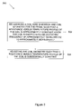
- FIG. 3 is a flow chart of an exemplary method of assembling the proximity probe shown in FIG. 2 .
- FIG. 1 is a schematic view of a proximity probe system 100 .
- Proximity probe system 100 is configured to monitor a target object, for example, a rotating shaft 102 of a machine (not shown).
- Proximity probe system 100 includes a proximity probe 104 including a temperature stable inductor 106 , an electronic circuit 108 and a monitoring system 110 .
- proximity probe 104 is operatively coupled to electronic circuit 108 and is positioned adjacent rotating shaft 102 for monitoring the vibrational or rotor position characteristics thereof.
- Proximity probe 104 uses eddy currents to generate a signal indicative of a gap 112 between rotating shaft 102 and inductor 106 .
- Proximity probe 104 includes a tuning disk 114 magnetically coupled to inductor 106 for setting a scale range for the output of proximity probe 104 .
- Proximity probe 104 defines a common enclosure 116 housing both inductor 106 and tuning disk 114 .
- proximity probe 104 is formed from a cured monolith of molded material 118 defining an encapsulation having a front end 120 and a back end 122 .
- Inductor 106 is generally symmetrically positioned within proximity probe 104 .
- An integrally formed protective probe tip 124 of a substantially uniform thickness 126 is fabricated along a forwardmost portion of proximity probe 104 .
- Molded material 118 substantially surrounds inductor 106 proximate front end 120 and ensconces a portion of an electrical conduit 128 that emanates from back end 122 .
- Tuning disk 114 is adjustable such that a distance 138 between inductor 106 and tuning disk 114 may be selected and maintained to facilitate controlling the output characteristics of proximity probe 104 .
- electrical conduit 128 comprises a multi-axis cable including a center conductor 140 electrically connected to a first lead 142 of inductor 106 and a coaxial conductor 144 electrically connected to a second lead 146 of inductor 106 wherein the center conductor 72 and coaxial conductor 74 are separated by an insulator or dielectric 148 .
- a braided sheath 150 circumscribes coaxial conductor 144 and is separated therefrom by an insulator 152 . Braided sheath 150 provides additional shielding and mechanical integrity to electrical conduit 128 .
- Electrical conduit 128 extends out of the back end 116 of the encapsulation 118 and couples inductor 106 to electronic circuit 108 to provide signal output and power input therebetween.
- Electronic circuit 108 is operatively coupled to inductor 106 for radiating energy in the form of an alternating magnetic field 158 from inductor 106 to rotating shaft 102 and for receiving signals from inductor 106 .
- Rotating shaft 102 absorbs some of this radiated energy and the received signals by electronic circuit 108 , from inductor 106 , are a function of the spacing between rotating shaft 102 and inductor 106 .
- the closer rotating shaft 102 is to inductor 106 the more energy rotating shaft 102 will absorb as a result of the eddy currents induced in rotating shaft 102 .
- the absorption of the radiated energy by shaft 102 is a result of the alternating magnetic field 158 generating eddy currents in shaft 102 which circulate so as to oppose magnetic field 158 , which created them.
- This action causes the resistance of the coil to change.
- the mutual effect of the currents in the closely adjacent conductors, turns of inductor 106 produce a temperature dependent change in resistance in response to the alternating current.
- the mutual effect of the currents in the closely adjacent turns of inductor 106 and the effect of the currents in shaft 102 produce temperature drift and gain variations in response to the alternating current.
- dimensions of inductor 106 and the wire comprising inductor 106 are preselected based on system performance requirements and the environment where proximity probe 104 is to operate. For example, a distance 112 may determine a diameter of proximity probe 104 and inductor 106 .
- a system operating frequency is determined based on the dimensions of inductor 106 and the dimensions and electrical characteristics of the wire used to form inductor 106 .
- the system operates at a specified frequency in order to provide an acceptable level of temperature stability. This frequency is theoretically determined, for example, using a computer programmed to determine the frequency based on the wire composition, diameter, and the geometrical configuration of the coil windings. This provides a baseline frequency at which the system will operate.
- the system is tested iteratively over its operating temperature range to determine the optimal operating frequency.
- the eddy current system is temperature stable when operating at a frequency between 150 kilohertz and 350 kilohertz. Specifically, for a 50 millimeter diameter probe configured as described herein the system is temperature stable when operating at a frequency of approximately 267 kilohertz.
- a linearly of a resistance versus temperature curve is determined empirically.
- the inductance of inductor 106 is adjusted, for example, by adding or removing winding turns to inductor 106 such that temperature drift and gain variations generated by both inductor 106 and target object (i.e., shaft 102 ) for effecting the temperature stable inductor 10 are substantially canceled out which results in a temperature stable proximity probe 104 .
- the temperature compensated proximity probe maintains an accurate indication of the gap 112 between rotating shaft 102 and inductor 106 under the temperature variations found in the environment of machine monitoring.
- FIG. 2 is an exploded perspective view of an exemplary proximity probe 104 in accordance with an embodiment of the present invention.
- Proximity probe 104 includes common enclosure 116 housing inductor 106 and tuning disk 114 .
- proximity probe 104 is formed from molded material 118 defining an encapsulation having a front end 120 and a back end 122 .
- Inductor 106 is generally symmetrically positioned within proximity probe 104 .
- An integrally formed protective probe tip 124 of a substantially uniform thickness 126 is fabricated along a forwardmost portion of proximity probe 104 . Molded material 118 substantially surrounds inductor 106 proximate front end 120 .
- a feed through boss 202 extends from back end 122 to guide and protect electrical conduit 128 (not shown in FIG. 2 ) from inductor 106 .
- Boss 202 includes a bore 204 therethough and a threaded portion 206 configured to threadably engage a threaded portion 208 of tuning disk tuning disk 114 .
- Tuning disk tuning disk 114 is adjustable such that a distance between inductor 106 and tuning disk 114 may be selected and maintained to facilitate controlling the output characteristics of proximity probe 104 .
- a weld ring 210 facilitates sealing a case 212 to enclosure 116 .
- FIG. 3 is a flow chart of an exemplary method 300 of assembling proximity probe 104 (shown in FIG. 2 ).
- the method includes determining 302 a coil wire dimension and coil geometry for the probe such that a resistance versus temperature profile of the coil is approximately constant when the coil is excited with an excitation frequency of approximately 150 kilohertz to approximately 350 kilohertz, and adjusting 304 the coil geometry such that a resistance versus temperature profile of the coil is substantially constant.
- the coil geometry is selected based on an application for the proximity probe. In the exemplary embodiment, a fifty millimeter diameter probe is selected. Selecting the coil geometry also includes selecting a wire diameter and material. An excitation to be applied to the probe during operation is determined using for example, a computer-based algorithm that determines a frequency of operation that facilitates reducing a temperature dependence of the output of the probe. In the exemplary embodiment, the algorithm uses the selected coil geometry and the coil wire dimensions and electrical characteristics to determine an operating frequency between approximately 150 kilohertz to approximately 350 kilohertz. The coil is subjected to output tests at various gap distances between the coil and a target.
- the ambient temperature of the probe is varied between temperature extremes expected to be experienced in the particular application the probe will be used in.
- the coil geometry is iteratively adjusted to attain a resistance versus temperature profile of the coil is substantially constant. For example, coil turns are added or removed to control the coil inductance such that the excitation frequency changes correlatively. In the exemplary embodiment, an operating frequency of approximately 267 kilohertz is the final operating frequency.
- a tuning disk comprising, in the exemplary embodiment, a stainless steel disk is positioned on an opposite side of the coil from the target. The tuning disk is magnetically coupled to the coil when an excitation signal is applied to the coil. The tuning disk is threadably coupled to a boss extending from the side of the coil enclosure. The scale factor of the coil is controlled by threading the tuning disk closer to the coil or further away from the coil. When the output scale factor is determined to be at the predetermined value, the tuning disk is locked in place and the proximity probe is further assembled.
- temperature stable proximity probe system provides a cost-effective and reliable means for monitoring machinery. More specifically, the coil of the proximity probe is fabricated such that an operating frequency is selected that substantially mitigates a temperature dependence of the output of the coil. As a result, an proximity based monitoring system is provided that facilitates improving the accuracy and repeatability of the proximity probe.
- monitoring system components illustrated are not limited to the specific embodiments described herein, but rather, components of each monitoring system may be utilized independently and separately from other components described herein.
- the monitoring system components described above may also be used in combination with other monitoring system.
Landscapes
- Physics & Mathematics (AREA)
- General Physics & Mathematics (AREA)
- Measurement Of Length, Angles, Or The Like Using Electric Or Magnetic Means (AREA)
- Measurement Of Mechanical Vibrations Or Ultrasonic Waves (AREA)
Abstract
Description
Claims (20)
Priority Applications (4)
| Application Number | Priority Date | Filing Date | Title |
|---|---|---|---|
| US11/335,201 US7239133B1 (en) | 2006-01-19 | 2006-01-19 | Methods and systems for controlling the temperature stability of an inductor |
| KR1020070005728A KR101281221B1 (en) | 2006-01-19 | 2007-01-18 | Methods and systems for controlling the temperature stability of an inductor |
| JP2007008872A JP5059422B2 (en) | 2006-01-19 | 2007-01-18 | Proximity probe and system for controlling the temperature stability of an inductor |
| CNA2007101385105A CN101126647A (en) | 2006-01-19 | 2007-01-19 | Methods and systems for controlling the temperature stability of an inductor |
Applications Claiming Priority (1)
| Application Number | Priority Date | Filing Date | Title |
|---|---|---|---|
| US11/335,201 US7239133B1 (en) | 2006-01-19 | 2006-01-19 | Methods and systems for controlling the temperature stability of an inductor |
Publications (2)
| Publication Number | Publication Date |
|---|---|
| US7239133B1 true US7239133B1 (en) | 2007-07-03 |
| US20070164735A1 US20070164735A1 (en) | 2007-07-19 |
Family
ID=38196802
Family Applications (1)
| Application Number | Title | Priority Date | Filing Date |
|---|---|---|---|
| US11/335,201 Active 2026-01-23 US7239133B1 (en) | 2006-01-19 | 2006-01-19 | Methods and systems for controlling the temperature stability of an inductor |
Country Status (4)
| Country | Link |
|---|---|
| US (1) | US7239133B1 (en) |
| JP (1) | JP5059422B2 (en) |
| KR (1) | KR101281221B1 (en) |
| CN (1) | CN101126647A (en) |
Cited By (2)
| Publication number | Priority date | Publication date | Assignee | Title |
|---|---|---|---|---|
| US8876483B2 (en) | 2010-01-14 | 2014-11-04 | Neptco, Inc. | Wind turbine rotor blade components and methods of making same |
| US10137542B2 (en) | 2010-01-14 | 2018-11-27 | Senvion Gmbh | Wind turbine rotor blade components and machine for making same |
Families Citing this family (4)
| Publication number | Priority date | Publication date | Assignee | Title |
|---|---|---|---|---|
| US10295693B2 (en) | 2014-05-15 | 2019-05-21 | Witricity Corporation | Systems, methods, and apparatus for foreign object detection loop based on inductive thermal sensing |
| US10302795B2 (en) | 2014-12-30 | 2019-05-28 | Witricity Corporation | Systems, methods, and apparatus for detecting ferromagnetic foreign objects in a predetermined space |
| US10324215B2 (en) | 2014-12-30 | 2019-06-18 | Witricity Corporation | Systems, methods, and apparatus for detecting ferromagnetic foreign objects in a predetermined space |
| CN109175587B (en) * | 2018-08-03 | 2021-01-26 | 东莞市众兴电子科技有限公司 | DC wire welding machine |
Citations (29)
| Publication number | Priority date | Publication date | Assignee | Title |
|---|---|---|---|---|
| US3471815A (en) | 1968-01-04 | 1969-10-07 | Bell Telephone Labor Inc | Temperature compensating inductor and circuit |
| US3564392A (en) | 1969-09-19 | 1971-02-16 | Gen Electric | Magnetic transducer with means for compensating for temperature changes |
| US3634799A (en) | 1969-04-18 | 1972-01-11 | Henrich Strauch | Inductive transducers |
| US3694785A (en) | 1972-02-22 | 1972-09-26 | Pickering & Co Inc | Temperature compensating differential transformer |
| US3750010A (en) | 1970-03-25 | 1973-07-31 | Reliance Electric Co | Vibration analyzer probe with reduced temperature sensitivity |
| US3939403A (en) | 1974-04-11 | 1976-02-17 | Stassart Marie Claire | Device for maintaining constant the temperature of a coil fed by an A.C. current source |
| US3992690A (en) | 1975-01-31 | 1976-11-16 | The Garrett Corporation | Composite electromagnetic coil |
| US3996510A (en) | 1975-03-12 | 1976-12-07 | General Electric Company | Shielding arrangement for sensing the proximity of a metallic object |
| US4214483A (en) | 1978-08-10 | 1980-07-29 | Arthur D. Little, Inc. | Apparatus for measuring angular speed |
| US4267508A (en) | 1978-04-11 | 1981-05-12 | Nippon Kokan Kabushiki Kaisha | Apparatus for non-contact measurement of distance from a metallic body using a detection coil in the feedback circuit of an amplifier |
| US4598260A (en) | 1984-04-18 | 1986-07-01 | Transducer Limited Partnership | Eddy current proximeter |
| US4651094A (en) | 1984-07-16 | 1987-03-17 | John Wallace | Accuracy control subsystem |
| US4652822A (en) | 1984-07-16 | 1987-03-24 | John Wallace | Multi-frequency eddy-current system and method |
| US4857842A (en) | 1987-06-03 | 1989-08-15 | Kineret Engineering | Temperature compensated hall effect position sensor |
| US4926123A (en) | 1988-01-22 | 1990-05-15 | Sunpower, Inc. | Precision variable pitch compensation winding for displacement transducer |
| US5027180A (en) | 1986-12-11 | 1991-06-25 | Mitsubishi Electric Corporation | Double gate static induction thyristor |
| US5089930A (en) | 1991-04-12 | 1992-02-18 | Pickering Controls, Inc. | Temperature compensated linear variable transformer |
| US5115193A (en) | 1990-12-05 | 1992-05-19 | Data Instruments, Inc. | Inductive linear displacement transducer and temperature-compensating signal processor |
| US5126664A (en) | 1990-12-18 | 1992-06-30 | Bently Nevada Corporation | Wire composition for a small diameter temperature stable proximity coil |
| US5270645A (en) | 1991-08-30 | 1993-12-14 | Nartron Corporation | Linear-output, temperature-stable rotational sensor including magnetic field responsive device disposed within a cavity of a flux concentrator |
| US5274328A (en) | 1992-07-20 | 1993-12-28 | Magnetek Inc. | Temperature compensation for magnetostrictive position detector |
| US5278523A (en) | 1989-01-13 | 1994-01-11 | Christian Lohse Beruhrungslose Schalttechnik | Temperature-stable tuned-circuit oscillator, especially in a proximity switch |
| US5332966A (en) | 1991-12-13 | 1994-07-26 | Vdo Adolf Schindling Ag | Method of compensating for the temperature of inductive sensors |
| US5351003A (en) | 1993-04-02 | 1994-09-27 | General Motors Corporation | Temperature compensated magnetoresistive position sensor |
| US5545983A (en) | 1992-03-02 | 1996-08-13 | Seiko Epson Corporation | Displacement sensor with temperature compensation by combining outputs in a predetermined ratio |
| US5574366A (en) | 1992-09-02 | 1996-11-12 | Tiefenbach Gmbh | Proximity switch having a variable sensing resistor for maintaining a constant total resistance |
| US5589768A (en) | 1990-07-30 | 1996-12-31 | Mitsubishi Steel Mfg. Co., Ltd. | Magnetoresistance-effect magnetic sensor of the temperature compensating type |
| US5608318A (en) | 1995-08-31 | 1997-03-04 | Mitsubishi Denki Kabushiki Kaisha | Inductive sensor circuit with coil resistance compensation |
| US6246229B1 (en) | 1999-05-12 | 2001-06-12 | Bently Nevada Corporation | Method and apparatus for controlling the temperature stability of an inductor using a magnetically coupled metallic object |
Family Cites Families (4)
| Publication number | Priority date | Publication date | Assignee | Title |
|---|---|---|---|---|
| JPS61184452A (en) * | 1985-02-12 | 1986-08-18 | Shimadzu Corp | Eddy current flaw detection apparatus |
| JP2733544B2 (en) * | 1990-05-30 | 1998-03-30 | 古河電気工業株式会社 | Conductive thin film inspection method |
| JP2533409B2 (en) * | 1990-11-30 | 1996-09-11 | 株式会社小松製作所 | Output signal processing device of detection coil |
| JPH11352109A (en) * | 1998-06-08 | 1999-12-24 | Sumitomo Metal Ind Ltd | Device and method for inspecting eddy current |
-
2006
- 2006-01-19 US US11/335,201 patent/US7239133B1/en active Active
-
2007
- 2007-01-18 KR KR1020070005728A patent/KR101281221B1/en active IP Right Grant
- 2007-01-18 JP JP2007008872A patent/JP5059422B2/en not_active Expired - Fee Related
- 2007-01-19 CN CNA2007101385105A patent/CN101126647A/en active Pending
Patent Citations (29)
| Publication number | Priority date | Publication date | Assignee | Title |
|---|---|---|---|---|
| US3471815A (en) | 1968-01-04 | 1969-10-07 | Bell Telephone Labor Inc | Temperature compensating inductor and circuit |
| US3634799A (en) | 1969-04-18 | 1972-01-11 | Henrich Strauch | Inductive transducers |
| US3564392A (en) | 1969-09-19 | 1971-02-16 | Gen Electric | Magnetic transducer with means for compensating for temperature changes |
| US3750010A (en) | 1970-03-25 | 1973-07-31 | Reliance Electric Co | Vibration analyzer probe with reduced temperature sensitivity |
| US3694785A (en) | 1972-02-22 | 1972-09-26 | Pickering & Co Inc | Temperature compensating differential transformer |
| US3939403A (en) | 1974-04-11 | 1976-02-17 | Stassart Marie Claire | Device for maintaining constant the temperature of a coil fed by an A.C. current source |
| US3992690A (en) | 1975-01-31 | 1976-11-16 | The Garrett Corporation | Composite electromagnetic coil |
| US3996510A (en) | 1975-03-12 | 1976-12-07 | General Electric Company | Shielding arrangement for sensing the proximity of a metallic object |
| US4267508A (en) | 1978-04-11 | 1981-05-12 | Nippon Kokan Kabushiki Kaisha | Apparatus for non-contact measurement of distance from a metallic body using a detection coil in the feedback circuit of an amplifier |
| US4214483A (en) | 1978-08-10 | 1980-07-29 | Arthur D. Little, Inc. | Apparatus for measuring angular speed |
| US4598260A (en) | 1984-04-18 | 1986-07-01 | Transducer Limited Partnership | Eddy current proximeter |
| US4651094A (en) | 1984-07-16 | 1987-03-17 | John Wallace | Accuracy control subsystem |
| US4652822A (en) | 1984-07-16 | 1987-03-24 | John Wallace | Multi-frequency eddy-current system and method |
| US5027180A (en) | 1986-12-11 | 1991-06-25 | Mitsubishi Electric Corporation | Double gate static induction thyristor |
| US4857842A (en) | 1987-06-03 | 1989-08-15 | Kineret Engineering | Temperature compensated hall effect position sensor |
| US4926123A (en) | 1988-01-22 | 1990-05-15 | Sunpower, Inc. | Precision variable pitch compensation winding for displacement transducer |
| US5278523A (en) | 1989-01-13 | 1994-01-11 | Christian Lohse Beruhrungslose Schalttechnik | Temperature-stable tuned-circuit oscillator, especially in a proximity switch |
| US5589768A (en) | 1990-07-30 | 1996-12-31 | Mitsubishi Steel Mfg. Co., Ltd. | Magnetoresistance-effect magnetic sensor of the temperature compensating type |
| US5115193A (en) | 1990-12-05 | 1992-05-19 | Data Instruments, Inc. | Inductive linear displacement transducer and temperature-compensating signal processor |
| US5126664A (en) | 1990-12-18 | 1992-06-30 | Bently Nevada Corporation | Wire composition for a small diameter temperature stable proximity coil |
| US5089930A (en) | 1991-04-12 | 1992-02-18 | Pickering Controls, Inc. | Temperature compensated linear variable transformer |
| US5270645A (en) | 1991-08-30 | 1993-12-14 | Nartron Corporation | Linear-output, temperature-stable rotational sensor including magnetic field responsive device disposed within a cavity of a flux concentrator |
| US5332966A (en) | 1991-12-13 | 1994-07-26 | Vdo Adolf Schindling Ag | Method of compensating for the temperature of inductive sensors |
| US5545983A (en) | 1992-03-02 | 1996-08-13 | Seiko Epson Corporation | Displacement sensor with temperature compensation by combining outputs in a predetermined ratio |
| US5274328A (en) | 1992-07-20 | 1993-12-28 | Magnetek Inc. | Temperature compensation for magnetostrictive position detector |
| US5574366A (en) | 1992-09-02 | 1996-11-12 | Tiefenbach Gmbh | Proximity switch having a variable sensing resistor for maintaining a constant total resistance |
| US5351003A (en) | 1993-04-02 | 1994-09-27 | General Motors Corporation | Temperature compensated magnetoresistive position sensor |
| US5608318A (en) | 1995-08-31 | 1997-03-04 | Mitsubishi Denki Kabushiki Kaisha | Inductive sensor circuit with coil resistance compensation |
| US6246229B1 (en) | 1999-05-12 | 2001-06-12 | Bently Nevada Corporation | Method and apparatus for controlling the temperature stability of an inductor using a magnetically coupled metallic object |
Cited By (5)
| Publication number | Priority date | Publication date | Assignee | Title |
|---|---|---|---|---|
| US8876483B2 (en) | 2010-01-14 | 2014-11-04 | Neptco, Inc. | Wind turbine rotor blade components and methods of making same |
| US9394882B2 (en) | 2010-01-14 | 2016-07-19 | Senvion Gmbh | Wind turbine rotor blade components and methods of making same |
| US9429140B2 (en) | 2010-01-14 | 2016-08-30 | Senvion Gmbh | Wind turbine rotor blade components and methods of making same |
| US9945355B2 (en) | 2010-01-14 | 2018-04-17 | Senvion Gmbh | Wind turbine rotor blade components and methods of making same |
| US10137542B2 (en) | 2010-01-14 | 2018-11-27 | Senvion Gmbh | Wind turbine rotor blade components and machine for making same |
Also Published As
| Publication number | Publication date |
|---|---|
| JP5059422B2 (en) | 2012-10-24 |
| KR20070077096A (en) | 2007-07-25 |
| KR101281221B1 (en) | 2013-07-02 |
| CN101126647A (en) | 2008-02-20 |
| JP2007199060A (en) | 2007-08-09 |
| US20070164735A1 (en) | 2007-07-19 |
Similar Documents
| Publication | Publication Date | Title |
|---|---|---|
| US7239133B1 (en) | Methods and systems for controlling the temperature stability of an inductor | |
| JP4960767B2 (en) | Displacement sensor | |
| EP2221625B1 (en) | Methods and systems for monitoring stator winding vibration | |
| JP2009528531A (en) | Position sensor | |
| US9791478B2 (en) | Current transducer of the Rogowksi type and arrangement for measuring a current | |
| CN111801558A (en) | Integration of proximity sensor with magnetostrictive torque sensor | |
| EP2698612B1 (en) | Extended stroke position sensor | |
| JP2019191060A (en) | NMR probe | |
| US6552667B1 (en) | Non-contact measuring method and apparatus for producing a signal representative of a distance between facing surfaces | |
| JP2012112944A (en) | Sensor assembly and method of measuring proximity of machine component to sensor | |
| US5206587A (en) | Inductive displacement transducer having telescoping probe assembly | |
| US6246229B1 (en) | Method and apparatus for controlling the temperature stability of an inductor using a magnetically coupled metallic object | |
| US20130119977A1 (en) | Sensing element for sensor assembly | |
| CN116930589A (en) | AC/DC multi-air gap magnetic resistance current sensor and current measuring method | |
| US8378683B2 (en) | Hall effect current sensor | |
| KR100912733B1 (en) | The cell resonator for the atom resonance apparatus | |
| CN104793048B (en) | The computational methods and device of adaptation loss power | |
| KR100511624B1 (en) | Sheet resistance measuring instrument of non contact | |
| CN207662339U (en) | A kind of eddy current displacement sensor sensitivity calibration device | |
| JPH04216401A (en) | Method and device for balancing displacement transducer measuring sequence through eddy current measuring method | |
| CN113834952B (en) | Device and method for realizing object acceleration measurement based on amorphous wire GSI effect | |
| JP2012112941A (en) | Sensor assembly and method for measuring proximity of component to emitter | |
| RU2482471C1 (en) | Method of eddy current control | |
| EP3904844A1 (en) | Method and system for non-invasive vibration-based condition monitoring of a machine | |
| CN111551581A (en) | Thermoelectric material performance measurement system |
Legal Events
| Date | Code | Title | Description |
|---|---|---|---|
| AS | Assignment |
Owner name: GENERAL ELECTRIC COMPANY, NEW YORK Free format text: ASSIGNMENT OF ASSIGNORS INTEREST;ASSIGNOR:BOWLDS, BRIAN BURKET;REEL/FRAME:017487/0445 Effective date: 20060119 |
|
| FEPP | Fee payment procedure |
Free format text: PAYOR NUMBER ASSIGNED (ORIGINAL EVENT CODE: ASPN); ENTITY STATUS OF PATENT OWNER: LARGE ENTITY |
|
| STCF | Information on status: patent grant |
Free format text: PATENTED CASE |
|
| REMI | Maintenance fee reminder mailed | ||
| FPAY | Fee payment |
Year of fee payment: 4 |
|
| SULP | Surcharge for late payment | ||
| FPAY | Fee payment |
Year of fee payment: 8 |
|
| MAFP | Maintenance fee payment |
Free format text: PAYMENT OF MAINTENANCE FEE, 12TH YEAR, LARGE ENTITY (ORIGINAL EVENT CODE: M1553); ENTITY STATUS OF PATENT OWNER: LARGE ENTITY Year of fee payment: 12 |
|
| AS | Assignment |
Owner name: BAKER HUGHES, A GE COMPANY, LLC, TEXAS Free format text: ASSIGNMENT OF ASSIGNORS INTEREST;ASSIGNOR:GENERAL ELECTRIC COMPANY;REEL/FRAME:051733/0574 Effective date: 20170703 |