US7231237B2 - Wireless communication device with strategically positioned antenna - Google Patents
Wireless communication device with strategically positioned antenna Download PDFInfo
- Publication number
- US7231237B2 US7231237B2 US11/216,776 US21677605A US7231237B2 US 7231237 B2 US7231237 B2 US 7231237B2 US 21677605 A US21677605 A US 21677605A US 7231237 B2 US7231237 B2 US 7231237B2
- Authority
- US
- United States
- Prior art keywords
- antenna
- wireless communication
- communication device
- resonator
- keypad
- Prior art date
- Legal status (The legal status is an assumption and is not a legal conclusion. Google has not performed a legal analysis and makes no representation as to the accuracy of the status listed.)
- Active, expires
Links
- 238000004891 communication Methods 0.000 title claims abstract description 76
- 238000000034 method Methods 0.000 claims description 23
- 230000008878 coupling Effects 0.000 claims description 3
- 238000010168 coupling process Methods 0.000 claims description 3
- 238000005859 coupling reaction Methods 0.000 claims description 3
- 230000005855 radiation Effects 0.000 description 8
- 230000000007 visual effect Effects 0.000 description 6
- 230000005540 biological transmission Effects 0.000 description 3
- 238000004590 computer program Methods 0.000 description 3
- 238000005516 engineering process Methods 0.000 description 3
- 239000000126 substance Substances 0.000 description 3
- 238000010295 mobile communication Methods 0.000 description 2
- 230000008859 change Effects 0.000 description 1
- 238000013461 design Methods 0.000 description 1
- 230000006870 function Effects 0.000 description 1
- 230000002452 interceptive effect Effects 0.000 description 1
- 238000012986 modification Methods 0.000 description 1
- 230000004048 modification Effects 0.000 description 1
- 230000008569 process Effects 0.000 description 1
- 238000006467 substitution reaction Methods 0.000 description 1
- 238000012546 transfer Methods 0.000 description 1
Images


Classifications
-
- H—ELECTRICITY
- H01—ELECTRIC ELEMENTS
- H01Q—ANTENNAS, i.e. RADIO AERIALS
- H01Q1/00—Details of, or arrangements associated with, antennas
- H01Q1/12—Supports; Mounting means
- H01Q1/22—Supports; Mounting means by structural association with other equipment or articles
- H01Q1/24—Supports; Mounting means by structural association with other equipment or articles with receiving set
- H01Q1/241—Supports; Mounting means by structural association with other equipment or articles with receiving set used in mobile communications, e.g. GSM
- H01Q1/242—Supports; Mounting means by structural association with other equipment or articles with receiving set used in mobile communications, e.g. GSM specially adapted for hand-held use
- H01Q1/243—Supports; Mounting means by structural association with other equipment or articles with receiving set used in mobile communications, e.g. GSM specially adapted for hand-held use with built-in antennas
-
- H—ELECTRICITY
- H01—ELECTRIC ELEMENTS
- H01Q—ANTENNAS, i.e. RADIO AERIALS
- H01Q1/00—Details of, or arrangements associated with, antennas
- H01Q1/36—Structural form of radiating elements, e.g. cone, spiral, umbrella; Particular materials used therewith
- H01Q1/38—Structural form of radiating elements, e.g. cone, spiral, umbrella; Particular materials used therewith formed by a conductive layer on an insulating support
-
- H—ELECTRICITY
- H04—ELECTRIC COMMUNICATION TECHNIQUE
- H04B—TRANSMISSION
- H04B1/00—Details of transmission systems, not covered by a single one of groups H04B3/00 - H04B13/00; Details of transmission systems not characterised by the medium used for transmission
- H04B1/38—Transceivers, i.e. devices in which transmitter and receiver form a structural unit and in which at least one part is used for functions of transmitting and receiving
- H04B1/3827—Portable transceivers
- H04B1/3833—Hand-held transceivers
-
- H—ELECTRICITY
- H04—ELECTRIC COMMUNICATION TECHNIQUE
- H04M—TELEPHONIC COMMUNICATION
- H04M1/00—Substation equipment, e.g. for use by subscribers
- H04M1/02—Constructional features of telephone sets
- H04M1/0202—Portable telephone sets, e.g. cordless phones, mobile phones or bar type handsets
- H04M1/026—Details of the structure or mounting of specific components
Definitions
- the present invention relates to antennas in a wireless communication device in general and global positioning system antennas used in the wireless communication device in particular.
- GPS global positioning system
- Conventional global positioning system (GPS) antennas are designed to have a strong directivity in the radiation pattern in the area directly facing the GPS satellites.
- the antenna rises out of the very top of the unit or is positioned near the top of the radio.
- a user will attempt to obtain a GPS fix by holding the mobile unit in a substantially horizontal position, which enables the user to better see the display.
- the keypad and the antenna of the mobile unit will also be in a substantially horizontal position.
- the radiation pattern for the GPS antenna is not suited for this type of situation, which may have a significant impact on the ability of the mobile unit to get fast and accurate GPS fixes.
- the present invention concerns a wireless communication device that can include at least one antenna.
- the antenna can be positioned beneath the face of a user interface of the wireless communication device in which the antenna can be configured to communicate with a signal source.
- the user interface can be positioned at a first surface of the wireless communication device.
- the antenna can have a stronger signal reception when the wireless communication device is positioned in a first position, as compared to the antenna being positioned in locations of the wireless communication device different from the first surface.
- the user interface can be a keypad in which the antenna can be positioned between the face of the keypad and a base plate of the keypad.
- the antenna can include a resonator and a transformer feeder point operatively coupled to the resonator in which a predetermined gap can be maintained between the resonator and the transformer feeder point.
- operatively coupled can be a capacitive coupling between the resonator and the transformer feeder point.
- the antenna can be substantially triangular in shape.
- the antenna can include one or more holes to accommodate one or more keypad buttons.
- the antenna can be a global positioning system antenna configured to at least receive global positioning system signals.
- a Bluetooth antenna or a wireless local access network antenna can be positioned adjacent to the antenna.
- the present invention also concerns a method of building a wireless communication device.
- the method can include the step of positioning at least one antenna beneath the face of a user interface of the wireless communication device in which the antenna is configured to communicate with a signal source.
- the antenna can include a resonator and a transformer feeder point operatively coupled to the resonator.
- the method can further include the step of positioning the resonator a predetermined distance away from the transformer feeder point.
- the positioning step can further include embedding the antenna between the face plate of the user interface and a base plate of the user interface in which the user interface is a keypad of the wireless communication device.
- the user interface can be positioned on a first surface of the wireless communication device, and the method can further include positioning the first surface in a first position to permit the antenna to at least substantially face the signal source.
- the signal source can be one or more global positioning system satellites.
- the present invention also concerns a wireless communication device that includes at least one antenna in which the antenna can be positioned beneath a face of a keypad.
- the antenna can receive an enhanced signal when the face of the keypad is exposed towards a signal source.
- the structure of this antenna and the type of signals that it can receive may be similar to the antenna described above, although the invention is not necessarily so limited.
- the antenna may include one or more holes to accommodate one or more keypad buttons.
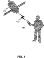
- FIG. 1 illustrates a wireless communication device receiving signal reception from a transmitting station pursuant to an embodiment of the present invention
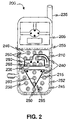
- FIG. 2 illustrates a wireless communication device with a faceplate showing an antenna as per an embodiment of the present invention
- FIG. 3 illustrates a method of building a wireless communication device having a strategically positioned antenna according to one embodiment of the present invention.
- the terms “a” or “an,” as used herein, are defined as one or more than one.
- the term “plurality,” as used herein, is defined as two or more than two.
- the term “another,” as used herein, is defined as at least a second or more.
- the terms “including” and/or “having,” as used herein, are defined as comprising (i.e., open language).
- the term “coupled,” as used herein, is defined as connected, although not necessarily directly, and not necessarily mechanically.
- the term “suppressing” can be defined as reducing or removing, either partially or completely.
- program is defined as a sequence of instructions designed for execution on a computer system.
- a program, computer program, or software application may include a subroutine, a function, a procedure, an object method, an object implementation, an executable application, an applet, a servlet, a source code, an object code, a shared library/dynamic load library and/or other sequence of instructions designed for execution on a computer system.
- a wireless communication device can receive signals from and transmit signals to base stations for data and voice communications using various antennas positioned within the wireless communication device.
- GPS Global Positioning System
- wireless communication devices specifically use GPS technology.
- Bluetooth, infrared, and other communication technologies are enabled due to transmitter and receiver antennas embedded in the wireless communication device.
- the position of the antenna is determined based on a direction of the signal reception. For example, known data and voice communication antennas on wireless communication devices are positioned on top of the wireless communication device to receive signals from all possible directions.
- the position of the antenna plays an integral role in receiving and transmitting an enhanced signal.
- An enhanced signal provides better quality for the user.
- an antenna with a radiation pattern pointing to the transmission source enables the wireless communication device to receive an enhanced signal as opposed to an antenna that is embedded deep within the wireless communication device.
- the visual display unit can also provide interference with signal reception if the antenna is positioned close to the visual display unit.
- the present invention can improve the ability of a wireless device to receive certain signals, such as GPS signals, because an antenna that can capture such signals can be strategically positioned to do so.
- the antenna can be positioned beneath a user interface, such as a keypad, which can cause the radiation pattern of the antenna to be better suited for the reception of GPS signals from GPS satellites when a user holds the wireless device in a substantially horizontal position to obtain a GPS fix.
- the wireless communication device 105 can be GPS-enabled and can receive signals from a transmitting station 115 as well as voice and data signals from a base station 110 on the ground.
- the transmitting station 115 can also be a satellite.
- the user also receives data and voice signals from the base station 110 .
- the wireless communication device 105 can include a GPS antenna that can be positioned beneath a user interface of the wireless communication device 105 , such as a keypad. Positioning the GPS antenna beneath the user interface provides an enhanced signal to the user when the GPS enabled wireless communication device is placed in a navigation mode.
- a navigation mode on a GPS enabled-wireless communication device is a mode where the wireless communication device is held to enable a user to obtain positional information.
- a user will position the wireless device 105 in a substantially horizontal position, with respect to the ground.
- the keypad on most mobile devices will be pointing substantially upwards towards the open sky.
- the user interface can be a keypad, and hence the antenna can be positioned between a face of the keypad and a base plate of the keypad of the wireless communication device 105 , as will be shown later. Positioning the antenna in this manner can provide a stronger signal reception as the wireless communication device 105 is placed in the navigation mode. The reception of these signals is enhanced because the antenna may be facing or at least substantially facing the signal source, such as one or more of the transmitting stations 115 , which also can cause the radiation pattern of the antenna to be directed to the signal source.
- the signal reception can be enhanced in relation to the antenna being positioned in certain other locations of the wireless communication device 105 , such as at the top of the wireless communication device 105 .
- the antenna can be positioned in other suitable locations (other than underneath the user interface) to improve the chances that the radiation pattern of the antenna may be directed towards the signal source.
- the antenna may not be restricted to a GPS antenna. Any antenna receiving and/or transmitting radio frequency signals may be positioned beneath the user interface to provide a better signal reception. For example, positioning a Bluetooth antenna or a wireless local area network (WLAN) beneath the user interface will reduce the interference that may be experienced from the visual display unit and therefore provide enhanced signal reception.
- WLAN wireless local area network
- a wireless communication device 200 (similar to the wireless communication device 105 of FIG. 1 ) is shown comprising an antenna 240 , according to one embodiment of the present invention.
- the wireless communication device 200 can include a visual display unit 205 and a user interface 245 , which can be a keypad 246 having one or more keypad buttons 250 .
- the keypad 246 can include a faceplate 252 and a base plate 255 , which is represented by a dashed outline.
- the antenna 240 can be placed between the faceplate 252 and the base plate 255 of the user interface 245 (or keypad 246 ).
- the base plate 255 can be positioned above a printed circuit board (PCB) (not shown), and the antenna 240 can rest on a top surface of the base plate 255 . Alternatively, the antenna 240 can rest on an inner surface of the faceplate 252 . Those of skill in the art, however, will appreciate that the antenna 240 does not necessarily have to be positioned between the face plate 252 and the base plate 255 , as other locations may be suitable.
- PCB printed circuit board
- the antenna 240 can further include a transformer feeder point 210 and a resonator 215 .
- the resonator 215 can contact a ground point (not shown) and the transformer feeder point 210 can contact a transmission line (not shown).
- the transmission line can have a characteristic impedance approximately equal to 50 ohms.
- a gap 230 can exist between the resonator 215 and the transformer feeder point 210 .
- a change in the location of the ground point may affect the performance of the antenna 240 , but the location of the transformer feeder point 210 can be changed without necessarily affecting the functioning of the antenna 240 .
- the transformer feeder point 210 can transmit and/or receive radio frequency signals to and from the resonator 215 .
- the resonator 215 and the transformer feeder point 210 can resonate at an operating frequency.
- the operating frequency can include but is not limited to GPS signals, which may have a frequency of approximately 1.575 GHz, with deviations above and below that value.
- GPS signals which may have a frequency of approximately 1.575 GHz, with deviations above and below that value.
- the invention is not so limited, as the antenna 240 may resonate at any other suitable operating frequencies.
- the antenna 240 can be positioned between the base plate 255 and the faceplate 252 of the keypad 246 .
- the antenna 240 can be manufactured thin enough to fit in the space between the base plate 255 and the face plate 252 of the keypad 246 .
- the antenna 240 can be located away from the visual display unit 205 . Hence, the interference from the visual display unit 205 may not affect the functioning or operating characteristics of the antenna 240 .
- a gap 230 can exist between the resonator 215 and the transformer feeder point 210 , which means that the resonator 215 and the transformer feeder point 210 can be capacitively coupled.
- the length of the gap 230 can vary, depending on design requirements.
- the invention is not limited in this regard, as the transformer feeder point 210 and the resonator 215 can be physically coupled to one another, if so desired.
- the resonator 215 can be substantially triangular in shape, although the resonator 215 can be in any other suitable shape.
- the bottom of the resonator 215 can taper, and the tip of the resonator 215 can be connected to a ground point (not shown) of the PCB (the base plate 255 can be configured to allow this connection).
- the antenna 240 can be kept relatively thin by not incorporating a dielectric substance on the antenna 240 . By avoiding such a dielectric substance, the antenna 240 can more easily fit between the base plate 255 and the face plate 252 . Air gaps between the antenna 240 and the base plate 255 and the face plate 252 can serve as a suitable substitute for such a dielectric substance.
- the antenna 240 can include one or more openings 260 . These openings 260 can be in the transformer feeder point 210 or the resonator 215 or both. In one arrangement, the openings 260 can receive one or more buttons 265 , such as the keypad buttons 250 , which can permit the buttons 265 to pass from the PCB to the outside of the face plate 252 , where they can be conventionally accessed by a user. This button 265 can include all the components necessary to receive a user's input and to transfer the input to the PCB. It has been shown, however, that these openings 260 do not substantially affect the performance of the antenna 240 , as it is still able to resonate in the desired frequencies. It should be noted that the openings 260 are not limited to receiving the buttons 265 , as other suitable components can pass through the openings 260 .
- the antenna 240 provided in the present invention can also be used as a secondary antenna along with a main subscriber antenna 235 .
- the antenna 235 can be used to transmit and receive conventional communications signals, such as wireless voice and data signals at various frequencies.
- the antenna 240 in its capacity as a secondary antenna, can enable the wireless communication device 105 to receive (or even transmit) GPS signals, without interfering with the operation of the main subscriber antenna 235 .
- the main subscriber antenna 235 will not affect the operation of the antenna 240 .
- the antenna 240 is not limited a GPS antenna, as the antenna 240 can be configured to receive and/or transmit other signals, such as Bluetooth or WLAN frequencies.
- antennas may be positioned near or adjacent to the antenna 240 .
- a Bluetooth antenna or a WLAN antenna can be placed near the antenna 240 without affecting the operation of either antenna.
- These additional antennas in view of their high resonating frequencies, can be made relatively small and can even be positioned on, for example, the inner surface of the face plate 252 or some other suitable surface.
- the method comprises the step of positioning an antenna beneath the face of a user interface of a wireless communication device in a manner that enables the antenna to communicate effectively with a signal source, as shown at step 305 .
- the user interface can be positioned on a first surface of the wireless communication device, as shown at step 320 .
- the first surface can be positioned in a first position to permit the antenna to face the signal source.
- the antenna can be a GPS antenna, and when a user puts the wireless device in a navigation mode, the antenna can face the signal source, which can be one or more GPS satellites.
- the first surface can be a surface of the base plate 255 or the face plate 252 . This process can result in the radiation pattern of the antenna being directed to the signal source. Further, this radiation pattern may not include any nulls in the navigation mode. By positioning the antenna in this way, the reception of the GPS signals can be enhanced, as compared to having the GPS signals received at an antenna that is positioned near the top of the wireless device, such as the main subscriber antenna 235 of FIG. 2 .
- the user interface can be a keypad, and hence the antenna can be embedded between a faceplate of the keypad and a base plate of the keypad, as shown at step 315 .
- Positioning the antenna beneath the user interface can further include positioning a resonator of the antenna at a predetermined distance from a transformer feeder point of the antenna, as shown at step 310 .
- other methods of positioning the antenna beneath a user interface of the wireless device are within contemplation of one or more of the inventive arrangements.
- a GPS-enabled wireless communication device used in the navigation mode shall provide less signal reception when the GPS antenna is not in a position that faces the signal source, for example, one or more GPS satellites.
- placing the antenna beneath the user interface, or a keypad facilitates the reception of the radio frequency signals when the keypad of the wireless communication device is held facing the signal source, which is a position where most users hold the wireless device when attempting to obtain GPS or location information.
- An enhanced signal can be understood as a stronger signal reception on the wireless communication device when the antenna is positioned on a first surface or location as compared to the antenna being positioned on a second, less desirable surface or location.
- the present invention can be realized in hardware, software or a combination of hardware and software. Any kind of computer system or other apparatus adapted for carrying out the methods described herein are suitable.
- a typical combination of hardware and software can be a mobile communications device with a computer program that, when being loaded and executed, can control the mobile communications device such that it carries out the methods described herein.
- Portions of the present invention may also be embedded in a computer program product, which comprises all the features enabling the implementation of the methods described herein and which when loaded in a computer system, is able to carry out these methods.
Landscapes
- Engineering & Computer Science (AREA)
- Computer Networks & Wireless Communication (AREA)
- Signal Processing (AREA)
- Telephone Set Structure (AREA)
- Position Fixing By Use Of Radio Waves (AREA)
- Support Of Aerials (AREA)
- Developing Agents For Electrophotography (AREA)
- Transceivers (AREA)
Priority Applications (5)
| Application Number | Priority Date | Filing Date | Title |
|---|---|---|---|
| US11/216,776 US7231237B2 (en) | 2005-08-31 | 2005-08-31 | Wireless communication device with strategically positioned antenna |
| EP06801315.0A EP1925167B1 (en) | 2005-08-31 | 2006-08-14 | Wireless communication device with strategically positioned antenna |
| KR1020107027088A KR20100133508A (ko) | 2005-08-31 | 2006-08-14 | 전략적으로 배치된 안테나를 갖는 무선 통신 디바이스 |
| PCT/US2006/031469 WO2007027411A2 (en) | 2005-08-31 | 2006-08-14 | Wireless communication device with strategically positioned antenna |
| KR1020087007724A KR20080039535A (ko) | 2005-08-31 | 2006-08-14 | 전략적으로 배치된 안테나를 갖는 무선 통신 디바이스 |
Applications Claiming Priority (1)
| Application Number | Priority Date | Filing Date | Title |
|---|---|---|---|
| US11/216,776 US7231237B2 (en) | 2005-08-31 | 2005-08-31 | Wireless communication device with strategically positioned antenna |
Publications (2)
| Publication Number | Publication Date |
|---|---|
| US20070049364A1 US20070049364A1 (en) | 2007-03-01 |
| US7231237B2 true US7231237B2 (en) | 2007-06-12 |
Family
ID=37805011
Family Applications (1)
| Application Number | Title | Priority Date | Filing Date |
|---|---|---|---|
| US11/216,776 Active 2025-11-17 US7231237B2 (en) | 2005-08-31 | 2005-08-31 | Wireless communication device with strategically positioned antenna |
Country Status (4)
| Country | Link |
|---|---|
| US (1) | US7231237B2 (ko) |
| EP (1) | EP1925167B1 (ko) |
| KR (2) | KR20080039535A (ko) |
| WO (1) | WO2007027411A2 (ko) |
Cited By (5)
| Publication number | Priority date | Publication date | Assignee | Title |
|---|---|---|---|---|
| US20070042706A1 (en) * | 2005-04-08 | 2007-02-22 | Vanderbilt University | System and methods of radio interference based localization in sensor networks |
| US20080055167A1 (en) * | 2005-09-15 | 2008-03-06 | Motorola, Inc. | Wireless communication device with integrated antenna |
| US20090289921A1 (en) * | 2008-05-23 | 2009-11-26 | Microsoft Corporation | Communications-enabled display console |
| US20140266926A1 (en) * | 2011-01-11 | 2014-09-18 | Apple Inc. | Engagement Features and Adjustment Structures for Electronic Devices with Integral Antennas |
| US9099771B2 (en) | 2011-01-11 | 2015-08-04 | Apple Inc. | Resonating element for reducing radio-frequency interference in an electronic device |
Families Citing this family (1)
| Publication number | Priority date | Publication date | Assignee | Title |
|---|---|---|---|---|
| KR20230038947A (ko) * | 2021-09-13 | 2023-03-21 | 삼성전자주식회사 | 안테나 및 그것을 포함하는 전자 장치 |
Citations (11)
| Publication number | Priority date | Publication date | Assignee | Title |
|---|---|---|---|---|
| US5561437A (en) * | 1994-09-15 | 1996-10-01 | Motorola, Inc. | Two position fold-over dipole antenna |
| US5710987A (en) * | 1993-02-25 | 1998-01-20 | Motorola, Inc. | Receiver having concealed external antenna |
| US5809433A (en) * | 1994-09-15 | 1998-09-15 | Motorola, Inc. | Multi-component antenna and method therefor |
| US6016126A (en) * | 1998-05-29 | 2000-01-18 | Ericsson Inc. | Non-protruding dual-band antenna for communications device |
| US6529749B1 (en) * | 2000-05-22 | 2003-03-04 | Ericsson Inc. | Convertible dipole/inverted-F antennas and wireless communicators incorporating the same |
| US6735630B1 (en) | 1999-10-06 | 2004-05-11 | Sensoria Corporation | Method for collecting data using compact internetworked wireless integrated network sensors (WINS) |
| US20040233109A1 (en) * | 2001-03-22 | 2004-11-25 | Zhinong Ying | Mobile communication device |
| US6826607B1 (en) | 1999-10-06 | 2004-11-30 | Sensoria Corporation | Apparatus for internetworked hybrid wireless integrated network sensors (WINS) |
| US6832251B1 (en) | 1999-10-06 | 2004-12-14 | Sensoria Corporation | Method and apparatus for distributed signal processing among internetworked wireless integrated network sensors (WINS) |
| US6859831B1 (en) | 1999-10-06 | 2005-02-22 | Sensoria Corporation | Method and apparatus for internetworked wireless integrated network sensor (WINS) nodes |
| US6885880B1 (en) * | 2000-09-22 | 2005-04-26 | Teleponaktiebolaget Lm Ericsson (Publ.) | Inverted-F antenna for flip-style mobile terminals |
Family Cites Families (12)
| Publication number | Priority date | Publication date | Assignee | Title |
|---|---|---|---|---|
| US6400996B1 (en) * | 1999-02-01 | 2002-06-04 | Steven M. Hoffberg | Adaptive pattern recognition based control system and method |
| US5701400A (en) * | 1995-03-08 | 1997-12-23 | Amado; Carlos Armando | Method and apparatus for applying if-then-else rules to data sets in a relational data base and generating from the results of application of said rules a database of diagnostics linked to said data sets to aid executive analysis of financial data |
| JP3430780B2 (ja) * | 1996-03-26 | 2003-07-28 | 松下電工株式会社 | 物体表面の形状検出方法 |
| US6006242A (en) * | 1996-04-05 | 1999-12-21 | Bankers Systems, Inc. | Apparatus and method for dynamically creating a document |
| US5966072A (en) * | 1996-07-02 | 1999-10-12 | Ab Initio Software Corporation | Executing computations expressed as graphs |
| US6088716A (en) * | 1997-04-28 | 2000-07-11 | Ab Initio Software Corporation | Method for preventing buffer deadlock in dataflow computations |
| US6173276B1 (en) * | 1997-08-21 | 2001-01-09 | Scicomp, Inc. | System and method for financial instrument modeling and valuation |
| US6208345B1 (en) * | 1998-04-15 | 2001-03-27 | Adc Telecommunications, Inc. | Visual data integration system and method |
| US6538651B1 (en) * | 1999-03-19 | 2003-03-25 | John Hayman | Parametric geometric element definition and generation system and method |
| US6816825B1 (en) * | 1999-06-18 | 2004-11-09 | Nec Corporation | Simulation vector generation from HDL descriptions for observability-enhanced statement coverage |
| KR100493073B1 (ko) * | 2002-12-06 | 2005-06-02 | 삼성전자주식회사 | 휴대용 무선 단말기의 안테나 장치 |
| ATE385052T1 (de) * | 2003-03-18 | 2008-02-15 | Sony Ericsson Mobile Comm Ab | Kompakte diversity-antenne |
-
2005
- 2005-08-31 US US11/216,776 patent/US7231237B2/en active Active
-
2006
- 2006-08-14 WO PCT/US2006/031469 patent/WO2007027411A2/en active Application Filing
- 2006-08-14 EP EP06801315.0A patent/EP1925167B1/en active Active
- 2006-08-14 KR KR1020087007724A patent/KR20080039535A/ko not_active Application Discontinuation
- 2006-08-14 KR KR1020107027088A patent/KR20100133508A/ko not_active Application Discontinuation
Patent Citations (11)
| Publication number | Priority date | Publication date | Assignee | Title |
|---|---|---|---|---|
| US5710987A (en) * | 1993-02-25 | 1998-01-20 | Motorola, Inc. | Receiver having concealed external antenna |
| US5561437A (en) * | 1994-09-15 | 1996-10-01 | Motorola, Inc. | Two position fold-over dipole antenna |
| US5809433A (en) * | 1994-09-15 | 1998-09-15 | Motorola, Inc. | Multi-component antenna and method therefor |
| US6016126A (en) * | 1998-05-29 | 2000-01-18 | Ericsson Inc. | Non-protruding dual-band antenna for communications device |
| US6735630B1 (en) | 1999-10-06 | 2004-05-11 | Sensoria Corporation | Method for collecting data using compact internetworked wireless integrated network sensors (WINS) |
| US6826607B1 (en) | 1999-10-06 | 2004-11-30 | Sensoria Corporation | Apparatus for internetworked hybrid wireless integrated network sensors (WINS) |
| US6832251B1 (en) | 1999-10-06 | 2004-12-14 | Sensoria Corporation | Method and apparatus for distributed signal processing among internetworked wireless integrated network sensors (WINS) |
| US6859831B1 (en) | 1999-10-06 | 2005-02-22 | Sensoria Corporation | Method and apparatus for internetworked wireless integrated network sensor (WINS) nodes |
| US6529749B1 (en) * | 2000-05-22 | 2003-03-04 | Ericsson Inc. | Convertible dipole/inverted-F antennas and wireless communicators incorporating the same |
| US6885880B1 (en) * | 2000-09-22 | 2005-04-26 | Teleponaktiebolaget Lm Ericsson (Publ.) | Inverted-F antenna for flip-style mobile terminals |
| US20040233109A1 (en) * | 2001-03-22 | 2004-11-25 | Zhinong Ying | Mobile communication device |
Cited By (8)
| Publication number | Priority date | Publication date | Assignee | Title |
|---|---|---|---|---|
| US20070042706A1 (en) * | 2005-04-08 | 2007-02-22 | Vanderbilt University | System and methods of radio interference based localization in sensor networks |
| US7558583B2 (en) * | 2005-04-08 | 2009-07-07 | Vanderbilt University | System and methods of radio interference based localization in sensor networks |
| US20080055167A1 (en) * | 2005-09-15 | 2008-03-06 | Motorola, Inc. | Wireless communication device with integrated antenna |
| US7468702B2 (en) | 2005-09-15 | 2008-12-23 | Motorola, Inc. | Wireless communication device with integrated antenna |
| US20090289921A1 (en) * | 2008-05-23 | 2009-11-26 | Microsoft Corporation | Communications-enabled display console |
| US20140266926A1 (en) * | 2011-01-11 | 2014-09-18 | Apple Inc. | Engagement Features and Adjustment Structures for Electronic Devices with Integral Antennas |
| US9002422B2 (en) * | 2011-01-11 | 2015-04-07 | Apple Inc. | Engagement features and adjustment structures for electronic devices with integral antennas |
| US9099771B2 (en) | 2011-01-11 | 2015-08-04 | Apple Inc. | Resonating element for reducing radio-frequency interference in an electronic device |
Also Published As
| Publication number | Publication date |
|---|---|
| KR20080039535A (ko) | 2008-05-07 |
| EP1925167A2 (en) | 2008-05-28 |
| EP1925167A4 (en) | 2008-10-08 |
| US20070049364A1 (en) | 2007-03-01 |
| WO2007027411A3 (en) | 2007-05-31 |
| WO2007027411A8 (en) | 2007-10-25 |
| EP1925167B1 (en) | 2015-03-25 |
| WO2007027411A2 (en) | 2007-03-08 |
| KR20100133508A (ko) | 2010-12-21 |
Similar Documents
| Publication | Publication Date | Title |
|---|---|---|
| US9287618B2 (en) | Mobile terminal | |
| US10211512B2 (en) | Multi-band antenna on the surface of wireless communication devices | |
| CN106575970B (zh) | 具有可调谐天线、可调节天线阻抗匹配电路和天线切换的电子设备 | |
| US6662028B1 (en) | Multiple frequency inverted-F antennas having multiple switchable feed points and wireless communicators incorporating the same | |
| EP2403057B1 (en) | Controlling a beamforming antenna using reconfigurable parasitic elements | |
| US7231237B2 (en) | Wireless communication device with strategically positioned antenna | |
| CN103051390A (zh) | 用于减小路径损耗的方法和设备 | |
| US20060164310A1 (en) | Double-layer antenna structure for hand-held devices | |
| EP1476961B1 (en) | System and method for providing gps-enabled wireless communications | |
| US20060119519A1 (en) | Antenna having radiating part formed flush with surface of casing part | |
| US20160209513A1 (en) | Electronic apparatus | |
| US20070010300A1 (en) | Wireless transceiving module with modularized configuration and method thereof | |
| US8914082B2 (en) | Mobile terminal and method of operating antenna thereof | |
| JP2008526167A (ja) | 衛星との通信を改善するための無線通信デバイス・アンテナ | |
| US20070218846A1 (en) | Radio comprising multiple transceivers | |
| US7388544B2 (en) | Antenna with a split radiator element | |
| US20060211373A1 (en) | Dual purpose multi-brand monopole antenna | |
| US8395553B2 (en) | Mobile terminal having antenna mounted in flexible PCB of side key | |
| JP2001102954A (ja) | 移動体通信端末 | |
| KR20130022682A (ko) | 이동 단말기의 위성 통신용 안테나 장치 | |
| US7342543B2 (en) | Electronic device to receive radio frequency signals | |
| US20080062048A1 (en) | Chip antenna module | |
| US20220181775A1 (en) | Electronic device including connector | |
| EP1710862A1 (en) | Dual purpose multi-band monopole antenna |
Legal Events
| Date | Code | Title | Description |
|---|---|---|---|
| AS | Assignment |
Owner name: MOTOROLA, INC., ILLINOIS Free format text: ASSIGNMENT OF ASSIGNORS INTEREST;ASSIGNORS:KINEZOS, CHRISTOS L.;MATTSSON, JAN-OVE U.;PONCE DE LEON, LORENZO A.;REEL/FRAME:016989/0713 Effective date: 20050831 |
|
| STCF | Information on status: patent grant |
Free format text: PATENTED CASE |
|
| FPAY | Fee payment |
Year of fee payment: 4 |
|
| AS | Assignment |
Owner name: MOTOROLA MOBILITY, INC, ILLINOIS Free format text: ASSIGNMENT OF ASSIGNORS INTEREST;ASSIGNOR:MOTOROLA, INC;REEL/FRAME:025673/0558 Effective date: 20100731 |
|
| AS | Assignment |
Owner name: MOTOROLA MOBILITY LLC, ILLINOIS Free format text: CHANGE OF NAME;ASSIGNOR:MOTOROLA MOBILITY, INC.;REEL/FRAME:029216/0282 Effective date: 20120622 |
|
| AS | Assignment |
Owner name: GOOGLE TECHNOLOGY HOLDINGS LLC, CALIFORNIA Free format text: ASSIGNMENT OF ASSIGNORS INTEREST;ASSIGNOR:MOTOROLA MOBILITY LLC;REEL/FRAME:034500/0001 Effective date: 20141028 |
|
| FPAY | Fee payment |
Year of fee payment: 8 |
|
| MAFP | Maintenance fee payment |
Free format text: PAYMENT OF MAINTENANCE FEE, 12TH YEAR, LARGE ENTITY (ORIGINAL EVENT CODE: M1553); ENTITY STATUS OF PATENT OWNER: LARGE ENTITY Year of fee payment: 12 |