US7202618B2 - Inverter device - Google Patents
Inverter device Download PDFInfo
- Publication number
- US7202618B2 US7202618B2 US11/293,914 US29391405A US7202618B2 US 7202618 B2 US7202618 B2 US 7202618B2 US 29391405 A US29391405 A US 29391405A US 7202618 B2 US7202618 B2 US 7202618B2
- Authority
- US
- United States
- Prior art keywords
- current
- rotor
- motor
- phase
- data table
- Prior art date
- Legal status (The legal status is an assumption and is not a legal conclusion. Google has not performed a legal analysis and makes no representation as to the accuracy of the status listed.)
- Expired - Fee Related
Links
- 230000000875 corresponding effect Effects 0.000 description 24
- 238000000034 method Methods 0.000 description 14
- 238000001514 detection method Methods 0.000 description 3
- 230000001276 controlling effect Effects 0.000 description 1
- 230000002596 correlated effect Effects 0.000 description 1
- 230000005669 field effect Effects 0.000 description 1
- 230000000630 rising effect Effects 0.000 description 1
- 230000001360 synchronised effect Effects 0.000 description 1
Images


Classifications
-
- H—ELECTRICITY
- H02—GENERATION; CONVERSION OR DISTRIBUTION OF ELECTRIC POWER
- H02M—APPARATUS FOR CONVERSION BETWEEN AC AND AC, BETWEEN AC AND DC, OR BETWEEN DC AND DC, AND FOR USE WITH MAINS OR SIMILAR POWER SUPPLY SYSTEMS; CONVERSION OF DC OR AC INPUT POWER INTO SURGE OUTPUT POWER; CONTROL OR REGULATION THEREOF
- H02M7/00—Conversion of AC power input into DC power output; Conversion of DC power input into AC power output
- H02M7/42—Conversion of DC power input into AC power output without possibility of reversal
- H02M7/44—Conversion of DC power input into AC power output without possibility of reversal by static converters
- H02M7/48—Conversion of DC power input into AC power output without possibility of reversal by static converters using discharge tubes with control electrode or semiconductor devices with control electrode
- H02M7/53—Conversion of DC power input into AC power output without possibility of reversal by static converters using discharge tubes with control electrode or semiconductor devices with control electrode using devices of a triode or transistor type requiring continuous application of a control signal
- H02M7/537—Conversion of DC power input into AC power output without possibility of reversal by static converters using discharge tubes with control electrode or semiconductor devices with control electrode using devices of a triode or transistor type requiring continuous application of a control signal using semiconductor devices only, e.g. single switched pulse inverters
- H02M7/5387—Conversion of DC power input into AC power output without possibility of reversal by static converters using discharge tubes with control electrode or semiconductor devices with control electrode using devices of a triode or transistor type requiring continuous application of a control signal using semiconductor devices only, e.g. single switched pulse inverters in a bridge configuration
-
- H—ELECTRICITY
- H02—GENERATION; CONVERSION OR DISTRIBUTION OF ELECTRIC POWER
- H02P—CONTROL OR REGULATION OF ELECTRIC MOTORS, ELECTRIC GENERATORS OR DYNAMO-ELECTRIC CONVERTERS; CONTROLLING TRANSFORMERS, REACTORS OR CHOKE COILS
- H02P27/00—Arrangements or methods for the control of AC motors characterised by the kind of supply voltage
- H02P27/04—Arrangements or methods for the control of AC motors characterised by the kind of supply voltage using variable-frequency supply voltage, e.g. inverter or converter supply voltage
- H02P27/06—Arrangements or methods for the control of AC motors characterised by the kind of supply voltage using variable-frequency supply voltage, e.g. inverter or converter supply voltage using DC to AC converters or inverters
- H02P27/08—Arrangements or methods for the control of AC motors characterised by the kind of supply voltage using variable-frequency supply voltage, e.g. inverter or converter supply voltage using DC to AC converters or inverters with pulse width modulation
-
- H—ELECTRICITY
- H02—GENERATION; CONVERSION OR DISTRIBUTION OF ELECTRIC POWER
- H02P—CONTROL OR REGULATION OF ELECTRIC MOTORS, ELECTRIC GENERATORS OR DYNAMO-ELECTRIC CONVERTERS; CONTROLLING TRANSFORMERS, REACTORS OR CHOKE COILS
- H02P6/00—Arrangements for controlling synchronous motors or other dynamo-electric motors using electronic commutation dependent on the rotor position; Electronic commutators therefor
- H02P6/14—Electronic commutators
- H02P6/16—Circuit arrangements for detecting position
- H02P6/18—Circuit arrangements for detecting position without separate position detecting elements
-
- H—ELECTRICITY
- H02—GENERATION; CONVERSION OR DISTRIBUTION OF ELECTRIC POWER
- H02P—CONTROL OR REGULATION OF ELECTRIC MOTORS, ELECTRIC GENERATORS OR DYNAMO-ELECTRIC CONVERTERS; CONTROLLING TRANSFORMERS, REACTORS OR CHOKE COILS
- H02P6/00—Arrangements for controlling synchronous motors or other dynamo-electric motors using electronic commutation dependent on the rotor position; Electronic commutators therefor
- H02P6/20—Arrangements for starting
Definitions
- the present invention relates to an inverter device which converts direct-current power to alternating-current power by respectively turning on and off a plurality of switching elements in order to drive a motor, and particularly to the detection of an initial position of a motor.
- FIG. 1 shows a conventional inverter device.
- An inverter device 80 shown in FIG. 1 converts direct-current power of a direct current source 81 such as a battery into alternating-current power in order to drive a three-phase motor 82 .
- the inverter 80 For example, in the inverter 80 , three pairs each including two switching elements connected in series to each other are respectively connected to the direct current source 81 in parallel, and respective midpoints of the three pairs of switching elements are connected to corresponding inputs of a U phase, a V phase and a W phase of the three-phase motor 82 . And, switching elements provided for respective phases in the inverter device 80 are sequentially turned on and off so that alternating-current power each having phases different by 120 degrees to each other are respectively supplied to the corresponding phases of the three-phase motor 82 . Thereby, the three-phase motor 82 is driven.
- the respective switching elements for example are PWM (Pulse Width Modulation) controlled based on currents flowing in the respective phases of the three-phases motor 82 , and the currents in the respective phases are obtained by current sensors or the like provided on the respective phases.
- PWM Pulse Width Modulation
- inductances of coils constituting the three-phase motor 82 are measured in advance corresponding to positions of a rotor of the three-phase motor 82 , a reference inductance is determined among the measured inductances, voltage pulses in three patterns are applied to the respective phases of the three-phase motor 82 , and the initial position of the rotor of the three-phase motor 82 is obtained based on a result of comparison between the reference inductance and the inductances corresponding to the respective patterns.
- the initial position of the rotor of the three-phase motor 82 is obtained by a calculation which utilizes detected currents in the respective phases of the three-phase motor 82 .
- noise components for example, a current error upon current detection due to a variation of characteristics in devices constituting the inverter such as current sensors, and current noise such as a ripple current or the like generated depending on a timing of turning on switching elements
- noise components included in the detected currents in the respective phases are also included in the calculation so that there is a probability that the noise components become more considerable.
- Patent Document 1
- Patent Document 2
- the inverter device comprises a plurality of switching elements which are provided in respective phases in a motor and which convert direct-current power into alternating-current power by being tuned on and off for driving the motor, a detecting unit for detecting a current in each phase in the motor, a control unit for controlling turning on and turning off of each of the plurality of switching elements, in which the control unit records, in advance, a current data table which specifies relationships between currents in the respective phases in the motor and positions of a rotor of the motor, and obtains, from the current data table, an initial position of the rotor corresponding to a current detected by the detecting unit before driving of the motor.
- a position of a rotor corresponding to a detected current is obtained from a current data table specifying a relationship between a current in each phase in the motor and the position of the rotor of the motor, accordingly, the initial position of the motor can be obtained without a calculation. Thereby, the initial position of the rotor of the motor can be obtained accurately because noise components of the detected current are not amplified by the calculation.
- a control unit in the above inverter device can obtain, from the current data table, the initial position of the rotor based on relationships among the currents in the respective phases detected by the detecting unit.
- the position of the rotor is a rotation angle of the rotor when one phase among the respective phases in the motor is a reference
- the current data table is divided into a plurality of areas with respect to the rotation angle of the rotor in advance
- the control unit finds a current data table which corresponds to a relationship among the currents in the respective phases detected by the detecting unit, among the plurality of current data tables, and sets, as the initial position of the rotor, a value which can be obtained by substituting a current detected by the detecting unit into a linear equation with a slope corresponding to an increase or a decrease of a current specified by the found current data table.
- the current data table is divided into a plurality of areas, and the initial position of the rotor is obtained by substituting a detected current into a linear equation corresponding to an increase or a decrease of the current on the corresponding current data table, therefore, the initial position of the rotor can be obtained highly accurately.
- the linear equation is a linear equation which corresponds to a current with a largest slope among currents in the respective phases in the motor in the found current data table.
- the initial position of the rotor can be obtained by substituting a detected current into a linear equation with the largest slope, accordingly, the initial position of the rotor can be obtained in a phase of a current with a high current variation rate, and therefore, the initial position of the rotor can be highly accurate.
- control unit in the above inverter device can record, in advance, an inductance data table which specifies relationships between inductances in coils constituting the motor and positions of the rotor of the motor, obtain, from the inductance data table, the position of the rotor corresponding to inductance based on a current detected by the detecting unit, and adjust the initial position of the rotor based on the obtained position of the rotor.
- the initial position of the rotor can be obtained by taking influence of a variation of inductance in accordance with a position of the rotor into account, accordingly, the initial position of the rotor can be obtained highly accurately further more.
- a control device is characterized in that it is provided in an inverter device including a plurality of switching elements provided in respective phases in a motor and converting direct-current power into alternating-current power by being tuned on and off for driving the motor and a detecting unit for detecting a current in each phase in the motor, controls turning on and turning off of each of the plurality of switching elements, records, in advance, a current data table which specifies relationships between currents in the respective phases in the motor and positions of a rotor of the motor, and obtains, from the current data table, an initial position of the rotor corresponding to a current detected by the detecting unit before driving of the motor.
- control device can obtain, from the current data table, the initial position of the rotor based on relationships among the currents in the respective phases detected by the detecting unit.
- the position of the rotor is a rotation angle of the rotor when one phase among the respective phases in the motor is a reference
- the current data table is divided into a plurality of areas with respect to the rotation angle of the rotor in advance, and the control device finds a current data table which corresponds to a relationship among the currents in the respective phases detected by the detecting unit, among the plurality of current data tables, and sets, as the initial position of the rotor, a value which can be obtained by substituting a current detected by the detecting unit into a linear equation with a slope corresponding to an increase or a decrease of a current specified by the found current data table.
- the linear equation can be a linear equation which corresponds to a current with a largest slope among currents in the respective phases in the motor in the found current data table.
- control device can record, in advance, an inductance data table which specifies relationships between inductances in coils constituting the motor and positions of the rotor of the motor, obtain, from the inductance data table, the position of the rotor corresponding to inductance based on a current detected by the detecting unit, and adjust the initial position of the rotor based on the obtained position of the rotor.
- an inductance data table which specifies relationships between inductances in coils constituting the motor and positions of the rotor of the motor
- the initial position of the rotor corresponding to a detected current is obtained from the current data table specifying a relationship between a current in each phase in the motor and the position of the rotor of the motor, accordingly, the initial position of the motor can be obtained without a calculation. Thereby, because noise components of the detected current are not amplified by a calculation, the initial position of the rotor of the motor can be obtained accurately.
- FIG. 1 shows a conventional inverter device
- FIG. 2 shows an inverter device according to the present invention
- FIG. 3 shows an example of a current data table as a graph
- FIG. 4 is a flowchart that explains operations of a control device in an embodiment of the present invention.
- FIG. 5A is a flowchart which explains operations in a step S 1 ;
- FIG. 5B shows a relationship between a voltage applied to one of respective phases in a three-phase motor and a current flowing in the above one phase
- FIG. 6 is a flowchart for explaining operation in a control device according to an embodiment of the present invention.
- FIG. 7A is a flowchart for the step S 5 to be executed when it is determined that +U phase current>+V phase current>+W phase current is satisfied;
- FIG. 7B shows a linear equation when a current which is determined to have the largest slope in the flowchart in FIG. 7A is approximated to a linear line
- FIG. 8 shows an example of an inductance data table as a graph.
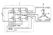
- FIG. 2 shows an inverter device according to the present invention. It is noted that like components to those in an inverter device 80 in FIG. 1 are denoted by like numerals. Also, a three-phase motor 82 in an inverter device 1 shown in FIG. 2 is, for example, a salient-pole permanent magnet synchronous motor. Also, the three-phase motor 82 in the inverter device 1 shown in FIG. 2 is, for example, a motor for a compressor.
- the inverter device 1 comprises switching elements 2 to 7 , current sensors 8 and 9 (detecting means) and a control device 10 (control means).
- FETs Field Effect Transistor
- IGBTs Insulated Gate Bipolar Transistor
- the switching elements 2 and 3 are connected in series to each other, the switching elements 4 and 5 are connected in series to each other, and the switching elements 6 and 7 are connected in series to each other.
- the above switching elements 2 to 7 are connected to a direct-current power source 81 in parallel.
- a midpoint of the switching elements 2 and 3 is connected to an input of a U phase of the three-phase motor 82
- a midpoint of the switching elements 4 and 5 is connected to an input of a V phase of the three-phase motor 82
- a midpoint of the switching elements 6 and 7 is connected to an input of a W phase of the three-phase motor 82 .
- CTs Current Transformer
- hole elements or the like can be used.
- the current sensor 8 is provided for the U phase
- the current sensor 9 is provided for the W phase. Additionally, currents in the respective phases in the three-phase motor 82 can be obtained based on voltages applied to shunt resistors in the respective phases.
- the above control device 10 comprises, for example, a CPU (Central Processing Unit) and the like, obtains a current in the U phase from the current sensor 8 , obtains a current in the W phase from the current sensor 9 , obtains a current in the V phase from total currents in the U phase and the W phase, and outputs drive signals based on the currents in the respective phases.
- a CPU Central Processing Unit
- the switching elements 2 to 7 are turned on and off respectively based on drive signals output from the control device 10 , and thereby, supplies, to the respective phases in the three-phase motor 82 , alternating-current power each having different phases by 120 degrees to each other so that the three-phase motor 82 is driven.
- the inverter device 1 is characterized in that the control device 10 records, in advance, a “current data table” which specifies relationships between currents in the respective phases in the three-phase motor 82 and positions of the rotor 83 in the three-phase motor 82 , and obtains the initial position of the rotor 83 in the three-phase motor 82 corresponding to currents in the respective phases in the three-phase motor 82 detected by the current sensors 8 and 9 before driving of the three-phase motor 82 based on the “current data table” (map).
- a “current data table” specifies relationships between currents in the respective phases in the three-phase motor 82 and positions of the rotor 83 in the three-phase motor 82 , and obtains the initial position of the rotor 83 in the three-phase motor 82 corresponding to currents in the respective phases in the three-phase motor 82 detected by the current sensors 8 and 9 before driving of the three-phase motor 82 based on the “current data table” (map).
- FIG. 3 shows an example of the “current data table” as a graph.
- a vertical axis in the graph of FIG. 3 represents currents [A]
- a horizontal axis represents initial positions ⁇ [deg] of the rotor 83 of the three-phase motor 82 (for example, rotation angles 0 to 360 [deg] of the rotor 83 with respect to a coil that constitutes the U phase in the three-phase motor 82 shown in FIG. 2 as a reference).
- ⁇ [deg] of the rotor 83 of the three-phase motor 82 for example, rotation angles 0 to 360 [deg] of the rotor 83 with respect to a coil that constitutes the U phase in the three-phase motor 82 shown in FIG. 2 as a reference.
- a solid line denotes a U phase current when voltages are applied from the U phase to the V and W phases (hereinafter referred to as +U phase current)
- a dashed line denotes a V phase current when voltages are applied from the V phase to the U and W phases (hereinafter referred to as +V phase current)
- a dot/dash line denotes a W phase current when voltages are applied from the W phase to the U and V phases (hereinafter referred to as +W phase current).
- a solid line denotes a U phase current when voltages are applied from the V phase and W phase to the U phase (hereinafter referred to as ⁇ U phase current)
- a dashed line denotes a V phase current when voltages are applied from the U phase and the W phase to the V phase (hereinafter referred to as ⁇ V phase current)
- a dot/dash line denotes a W phase current when voltages are applied from the U phase and the V phase to the W phase (hereinafter referred to as ⁇ W phase current).
- the “current data table” recorded in the control device 10 is divided into a plurality of areas in advance by dividing the area ranging from 0 degree to 360 degrees as the rotation angle of the rotor 83 for each given range.
- the area of the rotation angle is divided into twelve areas (Pos 1 to Pos 12 ) in which initial positions of the rotor 83 when any two of the solid line (+U phase current), the dashed line (+V phase current) and the dot/dash line (+W phase current) cross each other are used as boundaries. Additionally, a manner of dividing the area in the “current data table” or the number of the areas is not limited.
- the control device 10 obtains the initial position of the rotor 83 by using the “current data table” which specifies relationships between currents in the respective phases in the three-phase motor 82 and the rotation angles of the rotor 83 , accordingly, the initial position of the rotor 83 can be obtained without a calculation. Thereby, the initial position of the rotor 83 can be obtained with high accuracy because the noise components are not amplified by calculations.
- FIG. 4 is a flowchart that explains operations of the control device 10 .
- the control device 10 obtains the +U phase current by applying a voltage from the U phase to the V and W phases, obtains the +V phase current by applying a voltage from the V phase to the U and W phases, obtains the +W phase current by applying a voltage from the W phase to the U and V phases, obtains the ⁇ U phase current by applying a voltage from the V and W phases to the U phase, obtains the ⁇ V phase current by applying a voltage from the U and W phases to the V phase, and obtains the ⁇ W phase current by applying a voltage from the U and V phases to the W phase.
- FIG. 5A is a flowchart which explains operations in the step S 1 .
- the control device 10 applies voltages to the respective phases in the three-phase motor 82 for an arbitrary period of time (this period of time can be varied by adjusting pulse width of the applied voltage, and is set such that sufficient currents flow in the respective phases in order to suppress influences by the noise components).
- control device 10 measures peaks of currents that have flowed in the respective phases.
- FIG. 5B shows a relationship between a voltage applied to one of the respective phases in the three-phase motor 82 and the current flowing in the above one phase.
- a vertical axis represents a magnitude of a voltage or a current
- a horizontal axis represents time.
- a solid line denotes a pulse voltage applied to one phase
- a dashed line denotes a current flowing in the above one phase.
- a peak of a current can be measured by measuring a current at the time of rising of the pulse voltage.
- the currents in the respective phases can be obtained by using the above equation (1).
- a step ST 3 in FIG. 5A the control device 10 determines whether or not currents in plus and minus directions in all the phases have been obtained, and when it is determined that the currents in the plus and minus directions in all the phases have been obtained, (Yes in the step ST 3 ), the process is ended. When it is determined that the currents in the plus and minus directions in all the phases have not been obtained, (No in the step ST 3 ), the process returns to the step ST 1 .
- control device 10 determines whether or not +U phase current is higher than the +V phase current.
- the control device 10 determines whether or not the +V phase current is higher than the +W phase current in a step S 3 .
- the control device 10 determines, in a step S 4 , that relationships among the +U phase current, the +V phase current and the +W phase current detected in the step S 1 satisfy an inequality of +U phase current>+V phase current>+W phase current. And the control device 10 determines that the initial position of the rotor 83 is in a range of a rotation angle specified by one of two areas Pos 6 and Pos 12 in the graph of FIG. 3 .
- control device 10 obtains an area corresponding to the current detected in the step S 1 among the above determined areas, and obtains the initial position of the rotor 83 in the determined area.
- the control device 10 determines whether or not the +U phase current is higher than the +W phase current in a step S 6 .
- the control device 10 determines, in a step S 7 , that relationships among the +U phase current, the +V phase current and the +W phase current detected in the step S 1 satisfy an inequality of +U phase current>+W phase current>+V phase current. And the control device 10 determines that the initial position of the rotor 83 is in a range of a rotation angle specified by one of two areas Pos 1 and Pos 7 in the graph of FIG. 3 . Thereafter, the process proceeds to a step S 5 .
- the control device 10 determines, in a step S 8 , that relationships among the +U phase current, the +V phase current and the +W phase current detected in the step S 1 satisfy an inequality of +W phase current>+U phase current>+V phase current. And the control device 10 determines that the initial position of the rotor 83 is in a range of a rotation angle specified by one of two areas Pos 2 and Pos 8 in the graph of FIG. 3 . Thereafter, the process proceeds to a step S 5 .
- the control device 10 determines whether or not the +U phase current is higher than the +W phase current in a step 9 .
- the control device 10 determines, in a step S 10 , that relationships among the +V phase current, the +U phase current and the +W phase current detected in the step S 1 satisfy an inequality of +V phase current>+U phase current>+W phase current. And the control device 10 determines that the initial position of the rotor 83 is in a range of a rotation angle specified by one of two areas Pos 5 and Pos 11 in the graph of FIG. 3 . Thereafter, the process proceeds to a step S 5 .
- the control device 10 determines whether or not the +V phase current is higher than the +W phase current in a step S 11 .
- the control device 10 determines, in a step S 12 , that relationships among the +V phase current, the +U phase current and the +W phase current detected in the step S 1 satisfy an inequality of +V phase current>+W phase current>+U phase current. And the control device 10 determines that the initial position of the rotor 83 is in a range of a rotation angle specified by one of two areas Pos 4 and Pos 10 in the graph of FIG. 3 . Thereafter, the process proceeds to a step S 5 .
- the control device 10 determines, in a step S 13 , that relationships among the +V phase current, the +U phase current and the +W phase current detected in the step SI satisfy an inequality of +W phase current>+V phase current>+U phase current. And the control device 10 determines that the initial position of the rotor 83 is in a range of a rotation angle specified by one of two areas Pos 3 and Pos 9 in the graph of FIG. 3 . Thereafter, the process proceeds to a step S 5 .
- FIG. 6 is a flowchart for explaining operation in the step S 5 .
- the control device 10 determines whether or not an absolute value of a positive current which is determined to be the highest in the steps S 4 , S 7 , S 8 , S 10 , S 12 or S 13 in FIG. 4 is higher than an absolute value of a negative current that corresponds to the above positive current.
- a step STP 2 the control device 10 determines one of the two areas which were determined in the steps S 4 , S 7 , S 8 , S 10 , S 12 or the S 13 in FIG. 4 based on a determination result in the step STP 1 .
- the rotation angle of the rotor 83 can be obtained based on the relationships among the currents in the respective phases, therefore, the initial position of the rotor 83 can be generally obtained without a calculation.
- a step STP 3 the control device 10 determines a phase in which a current with the largest slope in the determined area, and sets, as the initial position of the rotor 83 , a value which can be obtained by substituting a current detected by the current sensors 8 and 9 into a linear equation with the above largest slope.
- the control device 10 flows direct currents based on the obtained initial position of the rotor 83 in the respective phases, and fixes the initial position of the rotor 83 .
- the three-phase motor 82 can be started with zero errors regarding the initial position of the rotor 83 . Accordingly, torque can be produced more effectively upon starting the three-phase motor 82 .
- control device 10 records, in advance, a “slope data table” that specifies relationships between a given area among twelve areas and a phase of a current with the largest slope in that area, and a phase corresponding to the area determined in the step STP 2 is acquired from the “slope data table” in order to process the step STP 3 .
- control device 10 records, in advance, a “linear equation data table” which specifies relationships between a given area among the twelve areas and a linear equation, and a linear equation corresponding to the phase determined in the step STP 3 is acquired from the “linear equation data table” in order to process the step STP 3 .
- the rotation angle of the rotor 83 is obtained by substituting the detected current into a linear equation with the largest slope, accordingly, the initial position of the rotor 83 can be obtained with respect to a phase of a current with a high current variation rate, in other words, with respect to a phase of a current with less error. Further, the initial position of the rotor 83 can be obtained with higher accuracy.
- the respective flowcharts in FIG. 4 , FIG. 5A and FIG. 6 can be realized by a program corresponding to the flowcharts, which is recorded in a RAM (Random Access Memory), a ROM (Read Only Memory) or the like in advance, read out of the ROM, the RAM or the like, and executed by a CPU or the like.
- a RAM Random Access Memory
- ROM Read Only Memory
- FIG. 7A is a flowchart for the step S 5 to be executed when it is determined that +U phase current>+V phase current>+W phase current is satisfied.
- FIG. 7B shows a linear equation when a current which is determined to have the largest slope in the flowchart in FIG. 7A is approximated to a linear line.
- the control device 10 determines whether or not an absolute value of the +U phase current is higher than that of the ⁇ U phase current in the Pos 6 or the Pos 12 . Specifically, the control device 10 selects the Pos 6 when the absolute value of the +U phase current in the Pos 6 is higher than that of the -U phase current in the Pos 6 , and selects the Pos 12 when the absolute value of the +U phase current in the Pos 12 is higher than that of the ⁇ U phase current in the Pos 12 .
- the control device 10 selects the Pos 6 in the step STP 2 (S 4 ).
- the initial position of the rotor 83 is generally determined to be in the Pos 6
- the initial position x of the rotor 83 is 146.5 [deg] when the detected current in the U phase is 6 [A].
- the rotation angle of the rotor 83 is obtained by dividing the “current data table” into a plurality of areas and substituting a detected current into a linear equation corresponding to the current in the selected area, accordingly, the initial position of the rotor 83 can be obtained without a calculation.
- the initial position of the rotor 83 is obtained by using a data table, therefore, a cheap micro computer can constitute the control device 10 compared to the case where a calculation is required for obtaining the initial position of the rotor 83 . Accordingly, cost for the inverter device 1 can be reduced.
- the initial position of the rotor 83 can be obtained based on a variation of inductance of coils which constitute the three-phase motor 82 .
- FIG. 8 shows an example of an “inductance data table” (a map of inductance distribution in accordance with changes of the rotation angle of the rotor 83 ) as a graph.
- a vertical axis represents inductance L of a coil constituting the U phase in the three-phase motor 82
- a horizontal axis represents a rotation angle ⁇ [deg] of the rotor 83 in the three-phase motor 82 .
- a solid line denotes a variation of the inductance L in accordance with the rotation angle of the rotor 83
- a dashed line denotes a variation of the inductance L in accordance with the rotation angle of the rotor 83 with a magnetic pole opposite from that denoted by the solid line
- a data table corresponding to each line is recorded in a control device 2 .
- the control device 10 records, in advance, the “inductance data table” which specifies relationships between inductance and the rotation angles of the rotor 83 as shown in FIG. 8 , obtains, from the “inductance data table” (the “inductance data table” corresponding to the magnetic pole of the three-phase motor 82 when the initial position of the rot(r 83 is acquired from the “current data table”), the rotation angle of the rotor 83 corresponding to the inductance based on a current detected by the current sensors 8 and 9 , and adjusts the initial position of the rotor 83 acquired from the “current data table” by using the acquired rotation angle of the rotor 83 .
- a mean value between the initial position of the rotor 83 obtained from the “current data table” and the rotation angle of the rotor 83 acquired from the “inductance data table” is employed as a definitive initial position of the rotor 83 .
- the initial position of the rotor 83 can be obtained by taking influence of a variation of inductance in accordance with a rotation angle of the rotor 83 into account, accordingly, the initial position of the rotor 83 can be obtained more accurately.
- a configuration is employed in which the three-phase motor 82 is driven or stopped.
- a configuration is also possible in which a two-phase motor or a motor with four or more phases is driven or stopped.
- a configuration is employed in which direct-current power is supplied to the inverter device 1 from the direct current source 81 .
- direct-current power is supplied to the inverter device 1 from a direct current source which converts alternating-current power into direct-current power.
Landscapes
- Engineering & Computer Science (AREA)
- Power Engineering (AREA)
- Control Of Motors That Do Not Use Commutators (AREA)
- Control Of Ac Motors In General (AREA)
Abstract
Description
Claims (8)
Applications Claiming Priority (2)
| Application Number | Priority Date | Filing Date | Title |
|---|---|---|---|
| JP2004353403A JP4513536B2 (en) | 2004-12-06 | 2004-12-06 | Inverter device |
| JP2004-353403 | 2004-12-06 |
Publications (2)
| Publication Number | Publication Date |
|---|---|
| US20060119310A1 US20060119310A1 (en) | 2006-06-08 |
| US7202618B2 true US7202618B2 (en) | 2007-04-10 |
Family
ID=36035715
Family Applications (1)
| Application Number | Title | Priority Date | Filing Date |
|---|---|---|---|
| US11/293,914 Expired - Fee Related US7202618B2 (en) | 2004-12-06 | 2005-12-05 | Inverter device |
Country Status (5)
| Country | Link |
|---|---|
| US (1) | US7202618B2 (en) |
| EP (1) | EP1667316B1 (en) |
| JP (1) | JP4513536B2 (en) |
| KR (1) | KR100743415B1 (en) |
| CN (1) | CN100423443C (en) |
Cited By (10)
| Publication number | Priority date | Publication date | Assignee | Title |
|---|---|---|---|---|
| US20090218974A1 (en) * | 2005-09-02 | 2009-09-03 | Christian Paintz | Driving brushless dc (bldc) motors |
| US20100141192A1 (en) * | 2008-12-10 | 2010-06-10 | Melexis Tessenderlo Nv | Operation of bldc motors |
| US20110074327A1 (en) * | 2009-09-21 | 2011-03-31 | Melexis Tessenderlo Nv | Control of sinusoidally driven brushless dc (bldc) motors |
| US20110221371A1 (en) * | 2008-08-28 | 2011-09-15 | Melexis Nv, Microelectronic Integrated Systems | Accuracy of rotor position detection relating to the control of brushless dc motors |
| US20110241585A1 (en) * | 2010-03-31 | 2011-10-06 | Kabushiki Kaisha Toyota Jidoshokki | Direct-current to three-phase alternating-current inverter system |
| US8847531B2 (en) * | 2006-07-29 | 2014-09-30 | Ixys Ch Gmbh | Sample and hold time stamp for sensing zero crossing of back electromotive force in 3-phase brushless DC motors |
| US20150276181A1 (en) * | 2012-10-17 | 2015-10-01 | Guangzhou Haoyang Electronic Co., Ltd | Optical system for stage lamp |
| EP2963802A1 (en) | 2014-06-30 | 2016-01-06 | Schneider Toshiba Inverter Europe SAS | Control method for starting a synchronous electric motor |
| EP3128667A2 (en) | 2015-07-01 | 2017-02-08 | Schneider Toshiba Inverter Europe SAS | Control method for starting a synchronous electric motor |
| US20200067433A1 (en) * | 2018-08-21 | 2020-02-27 | Caterpillar Inc. | Switched reluctance motor control system |
Families Citing this family (24)
| Publication number | Priority date | Publication date | Assignee | Title |
|---|---|---|---|---|
| DE102005013773A1 (en) * | 2005-03-22 | 2006-09-28 | Diehl Ako Stiftung & Co. Kg | Electronic motor regulation for pump used in e.g. dishwasher, involves detecting and estimating rotor phase position and rotor speed of motor and determining fluctuations in rotor phase position and rotor speed to control pump operation |
| KR101268489B1 (en) * | 2006-08-04 | 2013-06-04 | 엘지전자 주식회사 | Method and apparatus for providng and using public traffic information containing bus stop-connected information |
| CN101512890B (en) * | 2006-09-26 | 2011-08-31 | 艾格瑞系统有限公司 | Systems and methods for controlling a DC motor |
| DE102008035232B4 (en) | 2007-07-30 | 2023-07-06 | GM Global Technology Operations LLC (n. d. Ges. d. Staates Delaware) | Compact connection arrangement for power converters |
| JP5238241B2 (en) * | 2007-12-21 | 2013-07-17 | 株式会社東芝 | Control device for synchronous motor |
| DE102009011674A1 (en) * | 2009-02-24 | 2010-09-02 | Hkr Climatec Gmbh | Method for operating electrical machine, involves feeding alternative voltages in one of stator windings, where alternative voltage has multiple voltage impulses |
| EP2292383B1 (en) * | 2009-09-04 | 2016-04-06 | Black & Decker Inc. | Redundant overspeed protection for power tools |
| CN101777861B (en) * | 2010-02-10 | 2012-07-11 | 株洲南车时代电气股份有限公司 | Initial positioning device of permanent synchronous motor |
| US20120181963A1 (en) * | 2011-01-19 | 2012-07-19 | Texas Instruments Incorporated | Initial position detection for a sensorless, brushless dc motor |
| JP5594160B2 (en) * | 2011-01-20 | 2014-09-24 | 株式会社豊田自動織機 | Method and apparatus for detecting deterioration of magnet with built-in electric motor |
| JP5719715B2 (en) * | 2011-07-26 | 2015-05-20 | 日立オートモティブシステムズ株式会社 | Inverter device |
| KR20150017413A (en) * | 2013-06-28 | 2015-02-17 | 삼성전기주식회사 | Circuit for detecting rotor position, apparatus and method for motor drive control using the same |
| JP6358144B2 (en) * | 2015-03-26 | 2018-07-18 | 株式会社豊田自動織機 | Control device and in-vehicle electric compressor |
| JP6539226B2 (en) * | 2015-06-16 | 2019-07-03 | キヤノン株式会社 | Motor drive |
| JP6528613B2 (en) * | 2015-09-02 | 2019-06-12 | トヨタ自動車株式会社 | Motor device |
| JP6514164B2 (en) * | 2016-09-06 | 2019-05-15 | 株式会社東芝 | Rotation position device for synchronous motor, air conditioner and washing machine |
| KR102619909B1 (en) * | 2016-09-09 | 2024-01-04 | 한온시스템 주식회사 | Apparatus and method for controlling a rotor of motor |
| JP6690498B2 (en) * | 2016-10-31 | 2020-04-28 | 株式会社豊田自動織機 | In-vehicle electric compressor |
| CN109428531B (en) * | 2017-08-24 | 2021-07-27 | 达明机器人股份有限公司 | How to determine the motor control angle |
| CN107894247B (en) * | 2017-10-11 | 2020-03-27 | 广州汽车集团股份有限公司 | Zero calibration method and system for rotary transformer of vehicle-mounted permanent magnet synchronous motor |
| CN108173475B (en) * | 2018-02-11 | 2020-06-02 | 矽力杰半导体技术(杭州)有限公司 | Motor drive device and motor |
| KR102030271B1 (en) * | 2018-03-28 | 2019-10-08 | 주식회사 세턴 | Apparatus for bldc motor control and method for initial position detecting of bldc motor using the same |
| JP7587476B2 (en) | 2021-06-01 | 2024-11-20 | キヤノン株式会社 | Motor control device and image forming apparatus |
| CN115603625B (en) * | 2022-10-24 | 2025-05-06 | 湖南擎舟芯源电子科技有限公司 | A method and system for detecting the initial position of a rotor of a permanent magnet synchronous motor |
Citations (10)
| Publication number | Priority date | Publication date | Assignee | Title |
|---|---|---|---|---|
| US4739240A (en) * | 1987-04-29 | 1988-04-19 | General Electric Company | Commutator for switched reluctance drive |
| US5107195A (en) * | 1991-02-11 | 1992-04-21 | General Electric Company | Rotor position estimator for a switched reluctance machine using a lumped parameter flux/current model |
| US5955860A (en) * | 1996-06-24 | 1999-09-21 | Toyota Jidosha Kabushiki Kaisha | Method of determining electrical angle and apparatus for the same |
| US6153956A (en) * | 1999-09-16 | 2000-11-28 | A. O. Smith Corporation | Switched reluctance position sensing |
| JP2001136779A (en) | 1999-11-05 | 2001-05-18 | Mitsubishi Heavy Ind Ltd | Initial-position detecting method for brushless dc motor and brushless dc motor equipped with initial-position detecting apparatus |
| US6291949B1 (en) * | 1998-12-21 | 2001-09-18 | Switched Reluctance Drives Limited | Control of switched reluctance machines |
| JP2002262600A (en) | 2001-03-02 | 2002-09-13 | Matsushita Electric Ind Co Ltd | Initial position detection device for permanent magnet synchronous motor |
| US20030111975A1 (en) * | 2001-12-18 | 2003-06-19 | Switched Reluctance Drives Limited | Rotor position detection of a switched reluctance drive |
| US6608462B2 (en) * | 2001-01-09 | 2003-08-19 | Switched Reluctance Drives Ltd. | Method and system for determining rotor position in a switched reluctance machine |
| US6957590B2 (en) * | 2003-02-28 | 2005-10-25 | Koyo Seiko Co., Ltd. | Rotational angle detecting apparatus and torque detecting apparatus |
Family Cites Families (6)
| Publication number | Priority date | Publication date | Assignee | Title |
|---|---|---|---|---|
| WO1994011945A1 (en) * | 1992-11-06 | 1994-05-26 | Georgia Tech Research Corporation | Method of observer-based control of permanent-magnet synchronous motors |
| JP3381408B2 (en) * | 1993-10-26 | 2003-02-24 | トヨタ自動車株式会社 | Electric angle detecting device and synchronous motor driving device using the same |
| US5448149A (en) * | 1994-06-20 | 1995-09-05 | Texas A&M University | Indirect rotor position sensor for a sinusoidal synchronous reluctance machine |
| KR100339564B1 (en) * | 1999-10-08 | 2002-06-03 | 구자홍 | Speed control method for switched reluctance motor |
| JP2003199388A (en) * | 2001-12-27 | 2003-07-11 | Sharp Corp | Motor drive |
| US20040108826A1 (en) * | 2002-12-10 | 2004-06-10 | Emerson Electric Co. | Method for characterizing a rotating electromagnetic machine |
-
2004
- 2004-12-06 JP JP2004353403A patent/JP4513536B2/en not_active Expired - Fee Related
-
2005
- 2005-12-01 EP EP05026278.1A patent/EP1667316B1/en not_active Expired - Lifetime
- 2005-12-03 KR KR1020050117301A patent/KR100743415B1/en not_active Expired - Fee Related
- 2005-12-05 US US11/293,914 patent/US7202618B2/en not_active Expired - Fee Related
- 2005-12-06 CN CNB2005101363944A patent/CN100423443C/en not_active Expired - Fee Related
Patent Citations (10)
| Publication number | Priority date | Publication date | Assignee | Title |
|---|---|---|---|---|
| US4739240A (en) * | 1987-04-29 | 1988-04-19 | General Electric Company | Commutator for switched reluctance drive |
| US5107195A (en) * | 1991-02-11 | 1992-04-21 | General Electric Company | Rotor position estimator for a switched reluctance machine using a lumped parameter flux/current model |
| US5955860A (en) * | 1996-06-24 | 1999-09-21 | Toyota Jidosha Kabushiki Kaisha | Method of determining electrical angle and apparatus for the same |
| US6291949B1 (en) * | 1998-12-21 | 2001-09-18 | Switched Reluctance Drives Limited | Control of switched reluctance machines |
| US6153956A (en) * | 1999-09-16 | 2000-11-28 | A. O. Smith Corporation | Switched reluctance position sensing |
| JP2001136779A (en) | 1999-11-05 | 2001-05-18 | Mitsubishi Heavy Ind Ltd | Initial-position detecting method for brushless dc motor and brushless dc motor equipped with initial-position detecting apparatus |
| US6608462B2 (en) * | 2001-01-09 | 2003-08-19 | Switched Reluctance Drives Ltd. | Method and system for determining rotor position in a switched reluctance machine |
| JP2002262600A (en) | 2001-03-02 | 2002-09-13 | Matsushita Electric Ind Co Ltd | Initial position detection device for permanent magnet synchronous motor |
| US20030111975A1 (en) * | 2001-12-18 | 2003-06-19 | Switched Reluctance Drives Limited | Rotor position detection of a switched reluctance drive |
| US6957590B2 (en) * | 2003-02-28 | 2005-10-25 | Koyo Seiko Co., Ltd. | Rotational angle detecting apparatus and torque detecting apparatus |
Cited By (17)
| Publication number | Priority date | Publication date | Assignee | Title |
|---|---|---|---|---|
| US20090218974A1 (en) * | 2005-09-02 | 2009-09-03 | Christian Paintz | Driving brushless dc (bldc) motors |
| US8456117B2 (en) | 2005-09-02 | 2013-06-04 | Melexis Technologies Nv | Driving brushless DC (BLDC) motors |
| US8847531B2 (en) * | 2006-07-29 | 2014-09-30 | Ixys Ch Gmbh | Sample and hold time stamp for sensing zero crossing of back electromotive force in 3-phase brushless DC motors |
| US8674639B2 (en) | 2008-08-28 | 2014-03-18 | Melexis Technologies Nv | Accuracy of rotor position detection relating to the control of brushless DC motors |
| US20110221371A1 (en) * | 2008-08-28 | 2011-09-15 | Melexis Nv, Microelectronic Integrated Systems | Accuracy of rotor position detection relating to the control of brushless dc motors |
| US20100141192A1 (en) * | 2008-12-10 | 2010-06-10 | Melexis Tessenderlo Nv | Operation of bldc motors |
| US8593098B2 (en) * | 2008-12-10 | 2013-11-26 | Melexis Technologies Nv | Operation of BLDC motors |
| US20110074327A1 (en) * | 2009-09-21 | 2011-03-31 | Melexis Tessenderlo Nv | Control of sinusoidally driven brushless dc (bldc) motors |
| US8461789B2 (en) | 2009-09-21 | 2013-06-11 | Melexis Technologies Nv | Control of sinusoidally driven brushless DC (BLDC) motors |
| US20110241585A1 (en) * | 2010-03-31 | 2011-10-06 | Kabushiki Kaisha Toyota Jidoshokki | Direct-current to three-phase alternating-current inverter system |
| US8441225B2 (en) * | 2010-03-31 | 2013-05-14 | Kabushiki Kaisha Toyota Jidoshokki | Direct-current to three-phase alternating-current inverter system |
| US20150276181A1 (en) * | 2012-10-17 | 2015-10-01 | Guangzhou Haoyang Electronic Co., Ltd | Optical system for stage lamp |
| US9863607B2 (en) * | 2012-10-17 | 2018-01-09 | Guangzhou Haoyang Electronic Co., Ltd. | Optical system for stage lamp |
| EP2963802A1 (en) | 2014-06-30 | 2016-01-06 | Schneider Toshiba Inverter Europe SAS | Control method for starting a synchronous electric motor |
| EP3128667A2 (en) | 2015-07-01 | 2017-02-08 | Schneider Toshiba Inverter Europe SAS | Control method for starting a synchronous electric motor |
| US20200067433A1 (en) * | 2018-08-21 | 2020-02-27 | Caterpillar Inc. | Switched reluctance motor control system |
| US10897217B2 (en) * | 2018-08-21 | 2021-01-19 | Caterpillar Inc. | Switched reluctance motor control system |
Also Published As
| Publication number | Publication date |
|---|---|
| CN100423443C (en) | 2008-10-01 |
| EP1667316B1 (en) | 2013-07-24 |
| KR20060063717A (en) | 2006-06-12 |
| JP4513536B2 (en) | 2010-07-28 |
| US20060119310A1 (en) | 2006-06-08 |
| EP1667316A3 (en) | 2009-03-04 |
| EP1667316A2 (en) | 2006-06-07 |
| JP2006166574A (en) | 2006-06-22 |
| KR100743415B1 (en) | 2007-07-30 |
| CN1819438A (en) | 2006-08-16 |
Similar Documents
| Publication | Publication Date | Title |
|---|---|---|
| US7202618B2 (en) | Inverter device | |
| EP2066022B1 (en) | Controller of Multi-Phase Electric Motor | |
| EP2066021B1 (en) | Controller of multi-phase electric motor | |
| US7088063B2 (en) | Motor drive device and integrated circuit device for motor driving | |
| US7483279B2 (en) | Apparatus and method for detecting phase currents of inverter | |
| US8872453B2 (en) | Motor drive controller and control method | |
| US8866421B2 (en) | Motor drive controller and control method | |
| US7952310B2 (en) | Controller of multi-phase electric motor | |
| US8223521B2 (en) | Inverter device | |
| US6873126B2 (en) | Motor drive method and motor driver | |
| US20070296371A1 (en) | Position sensorless control apparatus for synchronous motor | |
| US20210336568A1 (en) | Motor control apparatus and motor control apparatus control method | |
| JP2014155408A (en) | Motor control device | |
| US7640128B2 (en) | Rotor position detection in an electrical machine | |
| US7279863B2 (en) | Method and apparatus for detecting excitation position of SRM by comparison of detected current | |
| US7042191B2 (en) | Current detection unit of inverter | |
| JP4367256B2 (en) | Current correction control device and inverter device provided with current correction control device | |
| US11843335B2 (en) | Motor adjustment method | |
| KR100394690B1 (en) | Bldc motor-driving device for hybrid electric vehicle | |
| JP4393354B2 (en) | Brushless motor control apparatus, brushless motor apparatus, and brushless motor control method | |
| JPH118993A (en) | Reluctance motor torque control device |
Legal Events
| Date | Code | Title | Description |
|---|---|---|---|
| AS | Assignment |
Owner name: KABUSHIKI KAISHA TOYOTA JIDOSHOKKI, JAPAN Free format text: ASSIGNMENT OF ASSIGNORS INTEREST;ASSIGNORS:IDE, AKIRA;NAJIMA, KAZUKI;FUNATO, MOTONOBU;AND OTHERS;REEL/FRAME:017103/0702 Effective date: 20051214 |
|
| AS | Assignment |
Owner name: KABUSHIKI KAISHA TOYOTA JIDOSHOKKI, JAPAN Free format text: CORRECTIVE ASSIGNMENT TO CORRECT THE ASSIGNEE'S ADDRESS PREVIOUSLY RECORDED ON REEL 017103 FRAME 0702;ASSIGNORS:IDE, AKIRA;NAJIMA, KAZUKI;FUNATO, MOTONOBU;AND OTHERS;REEL/FRAME:018931/0828 Effective date: 20051214 |
|
| STCF | Information on status: patent grant |
Free format text: PATENTED CASE |
|
| FEPP | Fee payment procedure |
Free format text: PAYOR NUMBER ASSIGNED (ORIGINAL EVENT CODE: ASPN); ENTITY STATUS OF PATENT OWNER: LARGE ENTITY |
|
| FPAY | Fee payment |
Year of fee payment: 4 |
|
| FPAY | Fee payment |
Year of fee payment: 8 |
|
| FEPP | Fee payment procedure |
Free format text: MAINTENANCE FEE REMINDER MAILED (ORIGINAL EVENT CODE: REM.); ENTITY STATUS OF PATENT OWNER: LARGE ENTITY |
|
| LAPS | Lapse for failure to pay maintenance fees |
Free format text: PATENT EXPIRED FOR FAILURE TO PAY MAINTENANCE FEES (ORIGINAL EVENT CODE: EXP.); ENTITY STATUS OF PATENT OWNER: LARGE ENTITY |
|
| STCH | Information on status: patent discontinuation |
Free format text: PATENT EXPIRED DUE TO NONPAYMENT OF MAINTENANCE FEES UNDER 37 CFR 1.362 |
|
| FP | Lapsed due to failure to pay maintenance fee |
Effective date: 20190410 |