EP3128667A2 - Control method for starting a synchronous electric motor - Google Patents
Control method for starting a synchronous electric motor Download PDFInfo
- Publication number
- EP3128667A2 EP3128667A2 EP16172900.9A EP16172900A EP3128667A2 EP 3128667 A2 EP3128667 A2 EP 3128667A2 EP 16172900 A EP16172900 A EP 16172900A EP 3128667 A2 EP3128667 A2 EP 3128667A2
- Authority
- EP
- European Patent Office
- Prior art keywords
- current
- speed
- voltage
- module
- determining
- Prior art date
- Legal status (The legal status is an assumption and is not a legal conclusion. Google has not performed a legal analysis and makes no representation as to the accuracy of the status listed.)
- Granted
Links
- 238000000034 method Methods 0.000 title claims abstract description 31
- 230000001360 synchronised effect Effects 0.000 title claims abstract description 23
- 239000003550 marker Substances 0.000 claims abstract description 13
- 230000001131 transforming effect Effects 0.000 claims description 4
- 230000004907 flux Effects 0.000 description 17
- 235000021183 entrée Nutrition 0.000 description 12
- 230000008569 process Effects 0.000 description 7
- 238000004088 simulation Methods 0.000 description 7
- 230000009471 action Effects 0.000 description 3
- 238000004364 calculation method Methods 0.000 description 3
- 230000036461 convulsion Effects 0.000 description 3
- 230000009466 transformation Effects 0.000 description 3
- 239000010749 BS 2869 Class C1 Substances 0.000 description 2
- 238000010586 diagram Methods 0.000 description 2
- 238000005259 measurement Methods 0.000 description 2
- 239000004065 semiconductor Substances 0.000 description 2
- 230000000903 blocking effect Effects 0.000 description 1
- 238000004422 calculation algorithm Methods 0.000 description 1
- 239000003990 capacitor Substances 0.000 description 1
- 230000003247 decreasing effect Effects 0.000 description 1
- 230000000694 effects Effects 0.000 description 1
- 230000003631 expected effect Effects 0.000 description 1
- 239000011159 matrix material Substances 0.000 description 1
- 230000009022 nonlinear effect Effects 0.000 description 1
- 238000005070 sampling Methods 0.000 description 1
- 230000035945 sensitivity Effects 0.000 description 1
- 230000000087 stabilizing effect Effects 0.000 description 1
- 238000011144 upstream manufacturing Methods 0.000 description 1
Images

Classifications
-
- H—ELECTRICITY
- H02—GENERATION; CONVERSION OR DISTRIBUTION OF ELECTRIC POWER
- H02P—CONTROL OR REGULATION OF ELECTRIC MOTORS, ELECTRIC GENERATORS OR DYNAMO-ELECTRIC CONVERTERS; CONTROLLING TRANSFORMERS, REACTORS OR CHOKE COILS
- H02P1/00—Arrangements for starting electric motors or dynamo-electric converters
- H02P1/16—Arrangements for starting electric motors or dynamo-electric converters for starting dynamo-electric motors or dynamo-electric converters
- H02P1/46—Arrangements for starting electric motors or dynamo-electric converters for starting dynamo-electric motors or dynamo-electric converters for starting an individual synchronous motor
- H02P1/52—Arrangements for starting electric motors or dynamo-electric converters for starting dynamo-electric motors or dynamo-electric converters for starting an individual synchronous motor by progressive increase of frequency of supply to motor
-
- H—ELECTRICITY
- H02—GENERATION; CONVERSION OR DISTRIBUTION OF ELECTRIC POWER
- H02P—CONTROL OR REGULATION OF ELECTRIC MOTORS, ELECTRIC GENERATORS OR DYNAMO-ELECTRIC CONVERTERS; CONTROLLING TRANSFORMERS, REACTORS OR CHOKE COILS
- H02P1/00—Arrangements for starting electric motors or dynamo-electric converters
- H02P1/16—Arrangements for starting electric motors or dynamo-electric converters for starting dynamo-electric motors or dynamo-electric converters
- H02P1/46—Arrangements for starting electric motors or dynamo-electric converters for starting dynamo-electric motors or dynamo-electric converters for starting an individual synchronous motor
-
- H—ELECTRICITY
- H02—GENERATION; CONVERSION OR DISTRIBUTION OF ELECTRIC POWER
- H02P—CONTROL OR REGULATION OF ELECTRIC MOTORS, ELECTRIC GENERATORS OR DYNAMO-ELECTRIC CONVERTERS; CONTROLLING TRANSFORMERS, REACTORS OR CHOKE COILS
- H02P21/00—Arrangements or methods for the control of electric machines by vector control, e.g. by control of field orientation
- H02P21/34—Arrangements for starting
-
- H—ELECTRICITY
- H02—GENERATION; CONVERSION OR DISTRIBUTION OF ELECTRIC POWER
- H02P—CONTROL OR REGULATION OF ELECTRIC MOTORS, ELECTRIC GENERATORS OR DYNAMO-ELECTRIC CONVERTERS; CONTROLLING TRANSFORMERS, REACTORS OR CHOKE COILS
- H02P6/00—Arrangements for controlling synchronous motors or other dynamo-electric motors using electronic commutation dependent on the rotor position; Electronic commutators therefor
- H02P6/14—Electronic commutators
- H02P6/16—Circuit arrangements for detecting position
- H02P6/18—Circuit arrangements for detecting position without separate position detecting elements
- H02P6/181—Circuit arrangements for detecting position without separate position detecting elements using different methods depending on the speed
-
- H—ELECTRICITY
- H02—GENERATION; CONVERSION OR DISTRIBUTION OF ELECTRIC POWER
- H02P—CONTROL OR REGULATION OF ELECTRIC MOTORS, ELECTRIC GENERATORS OR DYNAMO-ELECTRIC CONVERTERS; CONTROLLING TRANSFORMERS, REACTORS OR CHOKE COILS
- H02P6/00—Arrangements for controlling synchronous motors or other dynamo-electric motors using electronic commutation dependent on the rotor position; Electronic commutators therefor
- H02P6/20—Arrangements for starting
-
- H—ELECTRICITY
- H02—GENERATION; CONVERSION OR DISTRIBUTION OF ELECTRIC POWER
- H02P—CONTROL OR REGULATION OF ELECTRIC MOTORS, ELECTRIC GENERATORS OR DYNAMO-ELECTRIC CONVERTERS; CONTROLLING TRANSFORMERS, REACTORS OR CHOKE COILS
- H02P2203/00—Indexing scheme relating to controlling arrangements characterised by the means for detecting the position of the rotor
- H02P2203/09—Motor speed determination based on the current and/or voltage without using a tachogenerator or a physical encoder
Definitions
- the present invention relates to a control method implemented in a variable speed drive for starting an electric motor connected to said variable speed drive.
- the control method applies to starting a synchronous electric motor and allows to align the rotor of this motor with a reference position.
- a variable speed drive comprises a rectifier module which supplies a DC voltage from an external AC supply network and an inverter (or chopper) module.
- This inverter module comprises power semiconductor electronic components for chopping the continuous voltage in Pulse Width Modulation PWM (PWM), so as to output a pulsed variable voltage voltage via a power cable. a variable frequency of rotation to the motor.
- PWM Pulse Width Modulation
- a drive controller controls conduction and blocking of the semiconductor components at the sampling rate to control the PWM motor with an appropriate variable voltage.
- a closed-loop speed controller for controlling a permanent magnet synchronous motor generally uses an absolute position sensor of the rotor.
- this type of sensor has a particularly high cost and reliability problems (need for additional cable, sensitivity to electromagnetic noise ). It is therefore known from the document JP1060287 to use an incremental encoder to know the relative position of the rotor. However the use of an incremental encoder requires knowing the initial position of the rotor.
- the document US 7,202,618 proposes a solution that is implemented in a variable speed drive to determine the initial position of the rotor in a three-phase electric motor.
- This solution consists of sending voltage pulses on each of the phases of the motor for a determined period of time and determining the peaks of currents having circulated in the phases of the motor. Then, by comparison between the currents obtained for each phase and from relations between the currents, the initial position of the rotor can be obtained without calculation.
- stored tables can determine without calculation the initial position of the rotor.
- the initial position of the rotor is certainly obtained without calculation but the various proposed solutions are complex and long to implement at each engine start.
- these methods are based on motor side effects (magnetic saturation, saliency ). However, there are engines that do not have enough saliency and others where the magnetic saturation does not have the expected effect. These prior methods may therefore fail.
- the object of the invention is to provide a method of controlling a synchronous electric motor that allows a simple, reliable and unrestrained alignment of the rotor in terms of alignment time and torque applied at startup. This process is based on the fundamental motor model and does not use side or non-linear effects. Thus it is robust and applicable to all types of synchronous motors (with magnet inside the rotor - IPM, with magnet on the surface of the rotor - SPM or variable reluctance motor - SynRM).
- the step of determining the voltage in the rotating marker is performed without control of the current by applying a U / F type control law.
- the module for determining the voltage in the rotating marker is implemented without control of the current by applying a U / F type control law.
- the solution does not consist in a determination of the initial angle of the rotor as is often the case in the solutions of the state of the art. In the present invention, it is indeed about determining a command to align the rotor at a selected reference position and defined by the reference velocity path applied at the input.
- the control method of the invention is implemented in a variable speed drive for starting a synchronous electric motor.
- the control method applies for any synchronous electric motor, for example variable reluctance type, permanent magnet smooth or salient, ...
- variable speed drive is connected upstream to an electrical distribution network N by three input phases R, S, T.
- the variable speed drive comprises an input stage consisting of a rectifier REC, by example of diode bridge type, arranged to rectify the AC voltage supplied by the network N.
- the variable speed drive also comprises a DC supply bus connected to the rectifier and comprising two power supply lines interconnected by one or more capacitors of bus.
- the frequency converter also comprises an output stage composed of an INV inverter receiving a DC voltage supplied by the DC supply bus and controlled to provide variable voltages at output to the synchronous electric motor M, in three output phases a, b, c.
- the control unit UC of the variable speed drive implements a main control law L for controlling the inverter and determining the output voltages necessary for the operation of the electric motor M (block B1 on the figure 2 ).
- this main control law L has as input a reference speed ⁇ ref from which it determines a reference torque current (not shown). It also receives as input a reference flow current Idref. From the reference torque current and the reference flow current and the measurements or estimates of the flow current Id and the torque current Iq, it determines reference voltages Vdref, Vqref from which the single voltages Va are determined. , Vb, Vc to be applied on each output phase (block B2).
- the position of the rotor is unknown to the control unit UC of the variable speed drive preventing the implementation of the main control law L.
- a specific sequence is implemented to align the rotor at a known position.
- the control method of the invention makes it possible to create a start sequence (ST, figure 2 ) in rotation of the engine. For starting the synchronous electric motor, the control method of the invention thus replaces the main control law L.
- the control method can determine (block B7) the voltages to be applied to the three output phases in order to allow the alignment of the rotor to a known position.
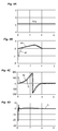
- FIGS. 4A to 4D, 5A to 5D and 6A to 6D illustrate simulation results for different cases of operation.
- the voltage Vdq generated follows a constant ( Figure 4A ) and the reference speed follows a predefined class C0 profile ( Figure 4B ).
- the figure 4C shows that the actual position of the rotor reaches the reference position at the end of the start-up process.
- the figure 4D shows that the torque C remains constant and that the startup process used does not generate jerks on the engine.
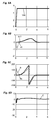
- the generated Vdq voltage follows a non-constant but continuous trajectory ( Figure 6A ) and the reference speed follows a predefined class C1 profile ( Figure 6B ).
- Figure 6C shows that the actual position of the rotor reaches the reference position at the end of the start-up process.
- the Figure 6D shows that the torque C remains constant and that the startup process used does not generate jerks on the engine.
- the determined reference position ⁇ s on which the rotor is aligned aligns directly with the actual position ⁇ of the rotor (block B8), which may be useful in the control in normal operation of the motor.
- the motor control is done via the input voltage and u dq and the reference speed ⁇ s .
- the system is stable if the three coefficients 1, fn p J M and 3 not p 2 ⁇ M I 2 J M cos ⁇ - ⁇ ⁇ eq are positive.
Abstract
L'invention concerne un procédé de commande mis en oeuvre dans un variateur de vitesse pour le démarrage d'un moteur électrique synchrone (M), ledit procédé comportant des étapes de : ¢ application en entrée d'une vitesse de référence (ws) suivant un profil de vitesse prédéfini, ¢ détermination d'une position de référence (¸s) à partir de la vitesse de référence appliquée en entrée, ¢ détermination d'une tension (Vdq) dans un repère tournant, à partir de la vitesse de référence appliquée en entrée, ¢ détermination de tensions de commande (Va, Vb, Vc) à appliquer sur chaque phase de sortie en fonction d'une part de la position de référence déterminée et d'autre part de ladite tension déterminée dans le repère tournant, ¢ application des tensions de commande (Va, Vb, Vc) sur chaque phase de sortie pour obtenir un alignement de la position du rotor dudit moteur sur la position de référence (¸s).The invention relates to a control method implemented in a variable speed drive for starting a synchronous electric motor (M), said method comprising steps of: € ¢ application at the input of a reference speed (ws) according to a predefined speed profile, € ¢ determination of a reference position (¸s) from the reference speed applied at the input, € ¢ determination of a voltage (Vdq) in a rotating marker, from the reference speed applied at the input, € ¢ determination of control voltages (Va, Vb, Vc) to be applied to each output phase as a function on the one hand of the determined reference position and on the other hand of said determined voltage in the rotating frame, € ¢ application of the control voltages (Va, Vb, Vc) on each output phase to obtain an alignment of the position of the rotor of said motor on the reference position (¸s).
Description
La présente invention se rapporte à un procédé de commande mis en oeuvre dans un variateur de vitesse pour le démarrage d'un moteur électrique connecté audit variateur de vitesse. Le procédé de commande s'applique au démarrage d'un moteur électrique synchrone et permet d'aligner le rotor de ce moteur avec une position de référence.The present invention relates to a control method implemented in a variable speed drive for starting an electric motor connected to said variable speed drive. The control method applies to starting a synchronous electric motor and allows to align the rotor of this motor with a reference position.
Il existe un grand nombre de méthodes différentes mises en oeuvre dans un variateur de vitesse pour déterminer la position initiale du rotor d'un moteur électrique synchrone à aimant permanent.There are a large number of different methods implemented in a variable speed drive to determine the initial position of the rotor of a permanent magnet synchronous electric motor.
De manière connue, un variateur de vitesse comporte un module redresseur qui fournit une tension continue à partir d'un réseau d'alimentation alternatif extérieur et un module onduleur (ou hacheur). Ce module onduleur comprend des composants électroniques semi-conducteurs de puissance pour hacher la tension continue en Modulation de Largeur d'Impulsion (MLI ou Pulse Width Modulation PWM), de façon à fournir en sortie via un câble de puissance une tension électrique variable pulsée et une fréquence de rotation variable au moteur. Un dispositif de commande du variateur contrôle la conduction et le blocage des composants semi-conducteurs à la fréquence d'échantillonnage, pour commander le moteur en MLI avec une tension variable appropriée.In known manner, a variable speed drive comprises a rectifier module which supplies a DC voltage from an external AC supply network and an inverter (or chopper) module. This inverter module comprises power semiconductor electronic components for chopping the continuous voltage in Pulse Width Modulation PWM (PWM), so as to output a pulsed variable voltage voltage via a power cable. a variable frequency of rotation to the motor. A drive controller controls conduction and blocking of the semiconductor components at the sampling rate to control the PWM motor with an appropriate variable voltage.
Un variateur de vitesse fonctionnant en boucle fermée pour la commande d'un moteur synchrone à aimants permanents utilise généralement un capteur de position absolue du rotor. Cependant, ce type de capteur présente un coût particulièrement élevé et des problèmes de fiabilité (nécessité d'un câble supplémentaire, sensibilité au bruit électromagnétique ...). Il est donc connu du document
Le document
Une autre méthode de détermination de la position initiale du rotor dans un moteur électrique synchrone est décrite dans la demande de brevet
Le but de l'invention est de proposer un procédé de commande d'un moteur électrique synchrone qui permette un alignement du rotor simple, fiable et sans contrainte en termes de durée d'alignement et de couple appliqué au démarrage. Ce procédé est basé sur le modèle fondamental du moteur et n'utilise pas les effets secondaires ou non linéaires. Ainsi il est robuste et applicable à tous les types de moteurs synchrones (avec aimant à l'intérieur du rotor - IPM, avec aimant sur la surface du rotor - SPM ou moteur à reluctance variable - SynRM).The object of the invention is to provide a method of controlling a synchronous electric motor that allows a simple, reliable and unrestrained alignment of the rotor in terms of alignment time and torque applied at startup. This process is based on the fundamental motor model and does not use side or non-linear effects. Thus it is robust and applicable to all types of synchronous motors (with magnet inside the rotor - IPM, with magnet on the surface of the rotor - SPM or variable reluctance motor - SynRM).
Ce but est atteint par un procédé de commande mis en oeuvre dans un variateur de vitesse pour le démarrage d'un moteur électrique synchrone doté d'un rotor et connecté par des phases de sortie audit variateur de vitesse, ledit procédé comprenant des étapes de :
- application en entrée d'une vitesse de référence suivant un profil de vitesse prédéfini, ledit profil de vitesse étant au moins continu et comportant une valeur initiale nulle, au moins une valeur non nulle afin de faire tourner le rotor dudit moteur et une valeur finale nulle,
- détermination d'une position de référence à partir de la vitesse de référence appliquée en entrée,
- détermination d'une tension dans un repère tournant à la vitesse du moteur électrique, à partir de la vitesse de référence appliquée en entrée,
- détermination de tensions de commande à appliquer sur chaque phase de sortie en fonction d'une part de la position de référence déterminée et d'autre part de ladite tension déterminée dans le repère tournant,
- application des tensions de commande sur chaque phase de sortie pour obtenir un alignement de la position du rotor dudit moteur sur la position de référence.
- application at the input of a reference speed according to a predefined speed profile, said speed profile being at least continuous and comprising a zero initial value, at least one non-zero value in order to rotate the rotor of said motor and a final zero value ,
- determination of a reference position from the reference speed applied at the input,
- determination of a voltage in a reference rotating at the speed of the electric motor, from the reference speed applied at the input,
- determination of control voltages to be applied to each output phase as a function, on the one hand, of the determined reference position and, on the other hand, of said determined voltage in the rotating reference mark,
- applying the control voltages on each output phase to obtain an alignment of the rotor position of said motor to the reference position.
Selon un premier mode de réalisation, l'étape de détermination de la tension dans le repère tournant est réalisée avec contrôle du courant et consiste à :
- mesurer les courants circulant sur les phases de sortie,
- transformer ces courants mesurés sur les trois phases de sortie en courant de flux mesuré et courant de couple mesuré,
- déterminer un courant de flux de référence et un courant de couple de référence à partir de la vitesse de référence injectée en entrée,
- déterminer la tension dans le repère tournant grâce à un régulateur à action proportionnelle intégrale recevant en entrée le courant de flux mesuré, le courant de couple mesuré, le courant de flux de référence et le courant de couple de référence.
- measure the currents flowing on the output phases,
- transforming these currents measured on the three output phases into measured flow current and measured torque current,
- determining a reference flow current and a reference torque current from the reference speed injected at the input,
- determining the voltage in the rotating reference mark by means of a proportional integral regulator receiving as input the measured flow current, the measured torque current, the reference flow current and the reference torque current.
Selon un deuxième mode de réalisation, l'étape de détermination de la tension dans le repère tournant est réalisée sans contrôle du courant en appliquant une loi de commande de type U/F.According to a second embodiment, the step of determining the voltage in the rotating marker is performed without control of the current by applying a U / F type control law.
L'invention concerne également un système de commande agencé dans un variateur de vitesse pour le démarrage d'un moteur électrique synchrone doté d'un rotor et connecté par des phases de sortie audit variateur de vitesse, ledit système comprenant :
- un module d'application en entrée d'une vitesse de référence suivant un profil de vitesse prédéfini, ledit profil de vitesse étant au moins continu et comportant une valeur initiale nulle, au moins une valeur non nulle afin de faire tourner le rotor dudit moteur et une valeur finale nulle,
- un module de détermination d'une position de référence à partir de la vitesse de référence appliquée en entrée,
- un module de détermination d'une tension dans un repère tournant à la vitesse du moteur électrique, à partir de la vitesse de référence appliquée en entrée,
- un module de détermination de tensions de commande à appliquer sur chaque phase de sortie en fonction d'une part de la position de référence déterminée et d'autre part de ladite tension déterminée dans le repère tournant,
- un module d'application des tensions de commande sur chaque phase de sortie pour obtenir un alignement de la position du rotor dudit moteur sur la position de référence.
- an application module inputting a reference speed according to a predefined speed profile, said speed profile being at least continuous and having an initial value of zero, at least one non-zero value in order to rotate the rotor of said engine and a final value of zero,
- a module for determining a reference position from the reference speed applied at the input,
- a module for determining a voltage in a reference rotating at the speed of the electric motor, from the reference speed applied at the input,
- a module for determining control voltages to be applied to each output phase as a function, on the one hand, of the determined reference position and, on the other hand, of said determined voltage in the rotating marker,
- a module for applying the control voltages on each output phase to obtain an alignment of the rotor position of said motor to the reference position.
Selon une première variante de réalisation, le module de détermination de la tension dans le repère tournant est mis en oeuvre avec contrôle du courant et comporte :
- un module de mesure des courants circulant sur les phases de sortie,
- un module de transformation des courants mesurés sur les trois phases de sortie en courant de flux mesuré et courant de couple mesuré,
- un module de détermination d'un courant de flux de référence et d'un courant de couple de référence à partir de la vitesse de référence injectée en entrée,
- un module de détermination de la tension dans le repère tournant grâce à un régulateur à action proportionnelle intégrale recevant en entrée le courant de flux mesuré, le courant de couple mesuré, le courant de flux de référence et le courant de couple de référence.
- a module for measuring the currents flowing on the output phases,
- a module for transforming currents measured on the three output phases measured current flow and measured torque current,
- a module for determining a reference flux current and a reference torque current from the reference speed injected at the input,
- a module for determining the voltage in the rotating marker by means of a proportional integral regulator receiving as input the measured flow current, the measured torque current, the reference flow current and the reference torque current.
Selon un deuxième mode de réalisation, le module de détermination de la tension dans le repère tournant est mis en oeuvre sans contrôle du courant en appliquant une loi de commande de type U/F.According to a second embodiment, the module for determining the voltage in the rotating marker is implemented without control of the current by applying a U / F type control law.
On comprend de cet exposé général de l'invention que la solution ne consiste pas en une détermination de l'angle initial du rotor comme c'est souvent le cas dans les solutions de l'état de la technique. Dans la présente invention, il s'agit en effet de déterminer une commande pour aligner le rotor sur une position de référence choisie et définie par la trajectoire de vitesse de référence appliquée en entrée.It is understood from this general statement of the invention that the solution does not consist in a determination of the initial angle of the rotor as is often the case in the solutions of the state of the art. In the present invention, it is indeed about determining a command to align the rotor at a selected reference position and defined by the reference velocity path applied at the input.
D'autres caractéristiques et avantages vont apparaître dans la description détaillée qui suit faite en regard des dessins annexés dans lesquels :
- la
figure 1 représente le schéma d'un variateur de vitesse connecté à un moteur électrique synchrone, - la
figure 2 représente de manière schématique le synoptique du procédé de commande de l'invention, - la
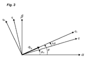
figure 3 illustre la représentation vectorielle d'un moteur synchrone dans un repère tournant, - les
figures 4A à 4D illustrent des résultats de simulation pour une première situation de fonctionnement, - les
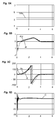
figures 5A à 5D illustrent des résultats de simulation pour une deuxième situation de fonctionnement, - les
figures 6A à 6D illustrent des résultats de simulation pour une troisième situation de fonctionnement.
- the
figure 1 represents the diagram of a variable speed drive connected to a synchronous electric motor, - the
figure 2 schematically represents the block diagram of the control method of the invention, - the
figure 3 illustrates the vector representation of a synchronous motor in a rotating marker, - the
Figures 4A to 4D illustrate simulation results for a first operating situation, - the
Figures 5A to 5D illustrate simulation results for a second operating situation, - the
Figures 6A to 6D illustrate simulation results for a third operating situation.
Le procédé de commande de l'invention est mis en oeuvre dans un variateur de vitesse pour le démarrage d'un moteur électrique synchrone. Le procédé de commande s'applique pour tout moteur électrique synchrone, par exemple de type à réluctance variable, à aimant permanent lisse ou saillant,...The control method of the invention is implemented in a variable speed drive for starting a synchronous electric motor. The control method applies for any synchronous electric motor, for example variable reluctance type, permanent magnet smooth or salient, ...
En référence à la
De manière connue, l'unité de commande UC du variateur de vitesse met en oeuvre une loi de commande principale L pour commander l'onduleur et déterminer les tensions de sortie nécessaires au fonctionnement du moteur électrique M (bloc B1 sur la
Au démarrage du moteur électrique M synchrone, la position du rotor est inconnue de l'unité de commande UC du variateur de vitesse empêchant la mise en oeuvre de la loi de commande principale L. Au démarrage du moteur électrique M synchrone, selon l'invention, une séquence spécifique est mise en oeuvre pour aligner le rotor sur une position connue. Le procédé de commande de l'invention permet de créer une séquence de démarrage (ST,
En référence à la
- la courbe du profil suit une fonction continue de classe au moins équivalente à C0,
- la vitesse de référence ωs initiale est nulle,
- la vitesse de référence ωs prend au moins une valeur non nulle afin de faire tourner le rotor,
- la vitesse de référence finale est nulle.
- the profile curve follows a class continuous function at least equivalent to C0,
- the reference speed ωs initial is zero,
- the reference speed ωs takes at least one non-zero value in order to rotate the rotor,
- the final reference speed is zero.
Avantageusement, le profil prédéfini comporte une valeur initiale nulle, suit une pente croissante jusqu'à une valeur maximale, puis une pente décroissante vers une valeur finale nulle. La valeur maximale de vitesse est déterminée en fonction du nombre de tours à appliquer au moteur électrique et de la durée d'alignement souhaitée. La fréquence maximale qui correspond à la valeur maximale de la vitesse appliquée au moteur suit ainsi la relation suivante : 
- RndNLD est le nombre des tours,
- (Tpw + Tmw) est la durée totale pour l'alignement,
- FDcMax est la fréquence maximale de rotation en Hz
- La relation entre la vitesse maximale ωsMax et la fréquence maximale FDcMax est : ωsMax = 2πFDcMax
- RndNLD is the number of towers,
- (T pw + T mw ) is the total duration for the alignment,
- F DcMax is the maximum frequency of rotation in Hz
- The relation between the maximum speed ω sMax and the maximum frequency F DcMax is: ω sMax = 2πF DcMax
En référence à la
- une position de référence θs (bloc B4) vers laquelle la position réelle du rotor doit tendre. La position de référence θs correspond à l'intégrale de la vitesse de référence ωs. L'expression de la fréquence de référence ƒs est :

- avec la fréquence de référence fs reliée à la vitesse de référence par ωS = 2πƒS ,
- FDcMax est la valeur maximale de la fréquence de référence,
- Tpw est le temps de montée de la fréquence de zéro à FDcMax,
- Tmw est le temps de descente de la fréquence de FDcMax à zéro.
- t est la durée depuis le début de la séquence d'alignement.
- La position de référence est obtenue par l'intégrale de la fréquence de référence comme suivant :
-

- La tension Vdq (bloc B5) à appliquer au moteur est déterminée avec contrôle ou sans contrôle du courant.
- a reference position θs (block B4) towards which the actual position of the rotor must extend. The reference position θs corresponds to the integral of the reference speed ωs. The expression of the reference frequency ƒ s is:
- with the reference frequency fs connected to the reference speed by ω S = 2 πƒ S ,
- FDcMax is the maximum value of the reference frequency,
- T pw is the rise time of the frequency from zero to FDcMax,
- T mw is the time of descent from the frequency of FDcMax to zero.
- t is the time since the start of the alignment sequence.
- The reference position is obtained by the integral of the reference frequency as follows:
-
- The voltage Vdq (block B5) to be applied to the motor is determined with control or without control of the current.
En référence à la
- mesurer les courants ia, ib, ic circulant sur les phases de sortie,
- transformer (bloc B6) ces courants mesurés sur les trois phases de sortie en courant de flux et courant de couple, grâce une transformation de Park,
- déterminer (bloc B5) un courant de flux de référence idref et un courant de couple de référence iqref à partir de la vitesse de référence injectée en entrée et qui suit le profil prédéfini ci-dessus,
- déterminer (bloc B5) la tension Vdq dans le repère tournant d,q grâce à un régulateur à action proportionnelle intégrale recevant en entrée le courant de flux id mesuré, le courant de couple iq mesuré, le courant de flux de référence idref et le courant de couple de référence iqref.
- measure currents ia, ib, ic flowing on the output phases,
- transform (block B6) these currents measured on the three output phases into current flow and torque current, thanks to a transformation of Park,
- determining (block B5) an idref reference flow current and a reference torque current iqref from the reference speed injected at the input and following the predefined profile above,
- determine (block B5) the voltage Vdq in the rotating reference mark d, q by means of an integral proportional proportional regulator receiving as input the stream current id measured, the measured torque current iq, the reference flux current idref and the current reference torque iqref.
Le courant de flux et le courant de couple de référence s'exprime par la relation suivante : 
- idMax est la valeur maximale du courant sur l'axe d.
- iqMax est la valeur maximale du courant sur l'axe q.
- ti est le temps de la rampe du courant au démarrage.
- TDcCurr est le temps du maintien du courant à la fin de la séquence d'alignement. Le but de ce courant continu à la fin de la séquence d'alignement est de s'assurer que le moteur est à l'arrêt à la position souhaitée.
- i dMax is the maximum value of the current on the axis d.
- i qMax is the maximum value of the current on the q axis.
- t i is the ramp up time of the start current.
- T DcCurr is the current hold time at the end of the alignment sequence. The purpose of this DC current at the end of the alignment sequence is to ensure that the motor is stopped at the desired position.
En variante de réalisation, la détermination de la tension Vdq sans contrôle du courant (c'est-à-dire en boucle ouverte, sans mesure des courants) consiste à :
- Déterminer (bloc B5) la tension de manière proportionnelle à la vitesse de référence (loi de commande de type U/F).
- Determine (block B5) the voltage in proportion to the reference speed (type U / F control law).
A partir de la tension Vdq et de la position de référence déterminée, le procédé de commande peut déterminer (bloc B7) les tensions à appliquer sur les trois phases de sortie en vue de permettre l'alignement du rotor sur une position connue. Les tensions de sortie s'expriment de la manière suivante : 
Les
Dans un premier cas de fonctionnement illustré par les
Dans un deuxième cas de fonctionnement illustré par les
Dans un troisième cas de fonctionnement illustré par les
Sur la
La démonstration qui suit permet de montrer que :
- Il existe des points d'équilibre au système, en fonction de la charge appliquée sur le moteur et de la tension qu'on lui applique,
- Ces points d'équilibre sont stables ou instables,
- Que le point d'équilibre qui nous intéresse (erreur d'angle minimum) est stable et atteignable.
- There are balance points in the system, depending on the load applied to the motor and the voltage applied to it,
- These equilibrium points are stable or unstable,
- That the equilibrium point of interest (minimum angle error) is stable and achievable.
Les équations d'un moteur synchrone dans un repère tournant (
-
-

-

-

- R, Ld, Lq et ϕM sont les paramètres électriques du moteur,
- JM et np sont les paramètres mécaniques du moteur,
- ƒ est le coefficient de frottement,
- TL est le couple de charge,
-

-

- θs est l'angle du contrôle, c'est-à-dire la position de référence,
- θ est la position réelle du rotor,
- Δθ = θ - θs,
-

-

-

-
-
-
-
- R, Ld, Lq and φ M are the electrical parameters of the motor,
- J M and np are the mechanical parameters of the motor,
- ƒ is the coefficient of friction,
- T L is the load torque,
-
-
- θ s is the angle of the control, ie the reference position,
- θ is the actual position of the rotor,
- Δ θ = θ - θ s ,
-
-
-
Le contrôle du moteur est fait via la tension d'entrée et udq et la vitesse de référence ωs . Comme la partie électrique est la plus rapide, et sans perte de généralité, nous considérons que le courant du moteur converge rapidement vers la référence du courant: ![]()
![]()
A titre d'exemple, nous détaillons ci-dessous la preuve de stabilité pour un moteur synchrone surfacique qui a les caractéristiques suivantes: Ld = Lq = L et µ = 0.By way of example, we detail below the proof of stability for a surface synchronous motor which has the following characteristics: L d = Lq = L and μ = 0.
Ainsi, pour prouver la convergence de l'angle il faut étudier les équations mécaniques du moteur qui s'écrivent dans ce cas comme suivant: 
![]()
![]()
Dans ce cas, le point d'équilibre est défini par : 
Nous proposons d'écrire les références des courants en format polaire comme suivant : ![]()
![]()
![]()
![]()
Ainsi, l'équilibre est défini par : 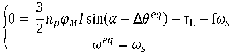
Finalement on obtient : 
Il y a deux points d'équilibre possibles : ![]()
![]()
Avec ![]()
![]()
![]()
![]()
Le système s'écrit comme suivant : 
La linéarisation de ce système autour de l'équilibre (Δθeq,ωeq ) donne : 
Les valeurs propres de la matrice de stabilité sont données par : ![]()
![]()
Le système est stable si les trois coefficients 1, ![]()
![]()
Par définition des positions d'équilibre, l'équilibre Δθeq = α - α 0 est stable tandis que l'équilibre Δθeq = α + α 0 - π est instable.By definition of equilibrium positions, the equilibrium Δ θ eq = α - α 0 is stable while the equilibrium Δ θ eq = α + α 0 - π is unstable.
Il en résulte que la seule position d'équilibre stable est Δθeq = α - α 0. La solution est donc : ![]()
![]()
Claims (6)
Applications Claiming Priority (1)
| Application Number | Priority Date | Filing Date | Title |
|---|---|---|---|
| FR1556191A FR3038469B1 (en) | 2015-07-01 | 2015-07-01 | CONTROL METHOD FOR STARTING A SYNCHRONOUS ELECTRIC MOTOR |
Publications (3)
| Publication Number | Publication Date |
|---|---|
| EP3128667A2 true EP3128667A2 (en) | 2017-02-08 |
| EP3128667A3 EP3128667A3 (en) | 2017-05-17 |
| EP3128667B1 EP3128667B1 (en) | 2024-02-28 |
Family
ID=54199829
Family Applications (1)
| Application Number | Title | Priority Date | Filing Date |
|---|---|---|---|
| EP16172900.9A Active EP3128667B1 (en) | 2015-07-01 | 2016-06-03 | Control method for starting a synchronous electric motor |
Country Status (4)
| Country | Link |
|---|---|
| US (1) | US10205411B2 (en) |
| EP (1) | EP3128667B1 (en) |
| CN (1) | CN106452226B (en) |
| FR (1) | FR3038469B1 (en) |
Citations (3)
| Publication number | Priority date | Publication date | Assignee | Title |
|---|---|---|---|---|
| JPH1060287A (en) | 1996-08-14 | 1998-03-03 | Matsushita Electric Works Ltd | Highly heat-conductive material, its production and floor heating system |
| EP1213828A1 (en) | 1999-09-17 | 2002-06-12 | Kabushiki Kaisha Yaskawa Denki | Initial magnetic pole estimating device for ac synchronous motor |
| US7202618B2 (en) | 2004-12-06 | 2007-04-10 | Kabushiki Kaisha Toyota Jidoshokki | Inverter device |
Family Cites Families (10)
| Publication number | Priority date | Publication date | Assignee | Title |
|---|---|---|---|---|
| US5998957A (en) * | 1997-04-29 | 1999-12-07 | Satcon Technology Corporation | Dissipativity-based controller for synchronous electric drives, and associated methods |
| US5929400A (en) * | 1997-12-22 | 1999-07-27 | Otis Elevator Company | Self commissioning controller for field-oriented elevator motor/drive system |
| JP4665360B2 (en) * | 2001-08-06 | 2011-04-06 | 株式会社安川電機 | Electric motor control device |
| JP4158101B2 (en) * | 2003-03-19 | 2008-10-01 | 日本パルスモーター株式会社 | Pulse generator IC for motor control |
| JP4901517B2 (en) * | 2007-02-08 | 2012-03-21 | 株式会社東芝 | AC motor controller |
| JP5547866B2 (en) * | 2007-06-19 | 2014-07-16 | 株式会社日立産機システム | Induction motor drive device, motor drive system, and lifting system |
| US8115441B2 (en) * | 2007-07-19 | 2012-02-14 | Hamilton Sundstrand Corporation | On-line measurement of an induction machine's rotor time constant by small signal d-axis current injection |
| FR2944659B1 (en) * | 2009-04-21 | 2011-04-01 | Schneider Toshiba Inverter | METHOD FOR DETERMINING THE POSITION OF THE FLOW VECTOR OF AN ENGINE |
| GB201012321D0 (en) | 2010-07-22 | 2010-09-08 | Artificial Lift Co Ltd | Control of a brushless dc motor over a long cable in a well |
| FR2972583B1 (en) * | 2011-03-11 | 2013-03-01 | Schneider Toshiba Inverter | CONTROL METHOD IN POWER CONVERTER TO IDENTIFY PARAMETERS RELATING TO THE MAGNETIC SATURATION OF AN ELECTRIC MOTOR |
-
2015
- 2015-07-01 FR FR1556191A patent/FR3038469B1/en active Active
-
2016
- 2016-06-03 EP EP16172900.9A patent/EP3128667B1/en active Active
- 2016-06-08 US US15/176,735 patent/US10205411B2/en active Active
- 2016-07-01 CN CN201610515585.XA patent/CN106452226B/en active Active
Patent Citations (3)
| Publication number | Priority date | Publication date | Assignee | Title |
|---|---|---|---|---|
| JPH1060287A (en) | 1996-08-14 | 1998-03-03 | Matsushita Electric Works Ltd | Highly heat-conductive material, its production and floor heating system |
| EP1213828A1 (en) | 1999-09-17 | 2002-06-12 | Kabushiki Kaisha Yaskawa Denki | Initial magnetic pole estimating device for ac synchronous motor |
| US7202618B2 (en) | 2004-12-06 | 2007-04-10 | Kabushiki Kaisha Toyota Jidoshokki | Inverter device |
Also Published As
| Publication number | Publication date |
|---|---|
| US10205411B2 (en) | 2019-02-12 |
| CN106452226B (en) | 2019-06-07 |
| FR3038469B1 (en) | 2017-06-23 |
| FR3038469A1 (en) | 2017-01-06 |
| EP3128667A3 (en) | 2017-05-17 |
| US20170005597A1 (en) | 2017-01-05 |
| CN106452226A (en) | 2017-02-22 |
| EP3128667B1 (en) | 2024-02-28 |
Similar Documents
| Publication | Publication Date | Title |
|---|---|---|
| EP2684289B1 (en) | Control method implemented in a power converter and intended for identifying parameters linked to the magnetic saturation of an electric motor | |
| EP2246973B1 (en) | Method for determining the position of the flux vector of a motor | |
| EP2294688B1 (en) | Method for determining the inductances of a permanent magnet synchronous machine | |
| EP2856632A1 (en) | Method for controlling the electromagnetic torque of a high speed synchronous machine | |
| EP3229366B1 (en) | Method for controlling an asynchronous electrical motor | |
| EP3157158A1 (en) | Control process for identifying the inductance values of a variable-reluctance synchronous electric motor | |
| EP3451525A1 (en) | Method for identifying magnetic saturation parameters of an asynchronous electric motor | |
| EP3401694B1 (en) | Method for identifying the electrical resistance of the rotor of an electric motor | |
| CA2861954C (en) | Control of a permanent-magnet electric machine | |
| EP2963802B1 (en) | Control method for starting a synchronous electric motor | |
| EP3503380B1 (en) | Method for controlling an electric motor including an identification sequence of a transformer | |
| EP3005548B1 (en) | Method for controlling a synchronous electrical machine, corresponding system and motor vehicle comprising the system | |
| EP3128667B1 (en) | Control method for starting a synchronous electric motor | |
| EP1484835B1 (en) | Method and system for regulating the instantaneous electromagnetic torque, and memory support for carrying out the method | |
| EP1727272B1 (en) | Deadbeat method and control unit for an asynchronous machine, storage means for said method | |
| EP3012962A1 (en) | Method for controlling a three-phase synchronous electric machine with a wound rotor | |
| EP3175544B1 (en) | Method and device for controlling the electromagnetic torque of a power train | |
| WO2015136173A2 (en) | Method and system for controlling a triple-phase electrical machine of a motor vehicle | |
| WO2023117402A1 (en) | Method and system for controlling an electric machine driven by an inverter provided with a plurality of switching arms | |
| FR3115425A1 (en) | Method and system for controlling an electrical machine determining optimal current setpoints | |
| WO2023073317A1 (en) | Method for automatically setting an angular position sensor | |
| FR3131993A1 (en) | Device and method for controlling a synchronous machine and estimating the rotor position, starting at a predetermined low speed | |
| FR3073691A1 (en) | METHOD FOR CONTROLLING A SYNCHRONOUS ELECTRIC MACHINE |
Legal Events
| Date | Code | Title | Description |
|---|---|---|---|
| PUAI | Public reference made under article 153(3) epc to a published international application that has entered the european phase |
Free format text: ORIGINAL CODE: 0009012 |
|
| STAA | Information on the status of an ep patent application or granted ep patent |
Free format text: STATUS: THE APPLICATION HAS BEEN PUBLISHED |
|
| AK | Designated contracting states |
Kind code of ref document: A2 Designated state(s): AL AT BE BG CH CY CZ DE DK EE ES FI FR GB GR HR HU IE IS IT LI LT LU LV MC MK MT NL NO PL PT RO RS SE SI SK SM TR |
|
| AX | Request for extension of the european patent |
Extension state: BA ME |
|
| PUAL | Search report despatched |
Free format text: ORIGINAL CODE: 0009013 |
|
| AK | Designated contracting states |
Kind code of ref document: A3 Designated state(s): AL AT BE BG CH CY CZ DE DK EE ES FI FR GB GR HR HU IE IS IT LI LT LU LV MC MK MT NL NO PL PT RO RS SE SI SK SM TR |
|
| AX | Request for extension of the european patent |
Extension state: BA ME |
|
| RIC1 | Information provided on ipc code assigned before grant |
Ipc: H02P 1/46 20060101AFI20170413BHEP Ipc: H02P 21/00 20160101ALI20170413BHEP Ipc: H02P 1/52 20060101ALI20170413BHEP Ipc: H02P 6/20 20160101ALI20170413BHEP |
|
| STAA | Information on the status of an ep patent application or granted ep patent |
Free format text: STATUS: REQUEST FOR EXAMINATION WAS MADE |
|
| 17P | Request for examination filed |
Effective date: 20170530 |
|
| RBV | Designated contracting states (corrected) |
Designated state(s): AL AT BE BG CH CY CZ DE DK EE ES FI FR GB GR HR HU IE IS IT LI LT LU LV MC MK MT NL NO PL PT RO RS SE SI SK SM TR |
|
| RIC1 | Information provided on ipc code assigned before grant |
Ipc: H02P 21/00 20160101ALI20180928BHEP Ipc: H02P 1/46 20060101ALI20180928BHEP Ipc: H02P 1/52 20060101ALI20180928BHEP Ipc: H02P 21/34 20160101AFI20180928BHEP Ipc: H02P 6/20 20160101ALI20180928BHEP |
|
| STAA | Information on the status of an ep patent application or granted ep patent |
Free format text: STATUS: EXAMINATION IS IN PROGRESS |
|
| 17Q | First examination report despatched |
Effective date: 20181115 |
|
| STAA | Information on the status of an ep patent application or granted ep patent |
Free format text: STATUS: EXAMINATION IS IN PROGRESS |
|
| GRAP | Despatch of communication of intention to grant a patent |
Free format text: ORIGINAL CODE: EPIDOSNIGR1 |
|
| STAA | Information on the status of an ep patent application or granted ep patent |
Free format text: STATUS: GRANT OF PATENT IS INTENDED |
|
| INTG | Intention to grant announced |
Effective date: 20230703 |
|
| GRAJ | Information related to disapproval of communication of intention to grant by the applicant or resumption of examination proceedings by the epo deleted |
Free format text: ORIGINAL CODE: EPIDOSDIGR1 |
|
| STAA | Information on the status of an ep patent application or granted ep patent |
Free format text: STATUS: EXAMINATION IS IN PROGRESS |
|
| GRAP | Despatch of communication of intention to grant a patent |
Free format text: ORIGINAL CODE: EPIDOSNIGR1 |
|
| STAA | Information on the status of an ep patent application or granted ep patent |
Free format text: STATUS: GRANT OF PATENT IS INTENDED |
|
| INTC | Intention to grant announced (deleted) | ||
| INTG | Intention to grant announced |
Effective date: 20230928 |
|
| GRAS | Grant fee paid |
Free format text: ORIGINAL CODE: EPIDOSNIGR3 |
|
| GRAA | (expected) grant |
Free format text: ORIGINAL CODE: 0009210 |
|
| STAA | Information on the status of an ep patent application or granted ep patent |
Free format text: STATUS: THE PATENT HAS BEEN GRANTED |
|
| AK | Designated contracting states |
Kind code of ref document: B1 Designated state(s): AL AT BE BG CH CY CZ DE DK EE ES FI FR GB GR HR HU IE IS IT LI LT LU LV MC MK MT NL NO PL PT RO RS SE SI SK SM TR |
|
| REG | Reference to a national code |
Ref country code: GB Ref legal event code: FG4D Free format text: NOT ENGLISH |
|
| REG | Reference to a national code |
Ref country code: CH Ref legal event code: EP |
|
| REG | Reference to a national code |
Ref country code: DE Ref legal event code: R096 Ref document number: 602016085982 Country of ref document: DE |