US7168832B2 - Vehicle headlamp - Google Patents
Vehicle headlamp Download PDFInfo
- Publication number
- US7168832B2 US7168832B2 US11/063,893 US6389305A US7168832B2 US 7168832 B2 US7168832 B2 US 7168832B2 US 6389305 A US6389305 A US 6389305A US 7168832 B2 US7168832 B2 US 7168832B2
- Authority
- US
- United States
- Prior art keywords
- light
- lens
- light source
- annular
- annular lens
- Prior art date
- Legal status (The legal status is an assumption and is not a legal conclusion. Google has not performed a legal analysis and makes no representation as to the accuracy of the status listed.)
- Expired - Fee Related, expires
Links
Images


Classifications
-
- G—PHYSICS
- G02—OPTICS
- G02B—OPTICAL ELEMENTS, SYSTEMS OR APPARATUS
- G02B3/00—Simple or compound lenses
- G02B3/02—Simple or compound lenses with non-spherical faces
- G02B3/08—Simple or compound lenses with non-spherical faces with discontinuous faces, e.g. Fresnel lens
-
- F—MECHANICAL ENGINEERING; LIGHTING; HEATING; WEAPONS; BLASTING
- F21—LIGHTING
- F21S—NON-PORTABLE LIGHTING DEVICES; SYSTEMS THEREOF; VEHICLE LIGHTING DEVICES SPECIALLY ADAPTED FOR VEHICLE EXTERIORS
- F21S41/00—Illuminating devices specially adapted for vehicle exteriors, e.g. headlamps
- F21S41/10—Illuminating devices specially adapted for vehicle exteriors, e.g. headlamps characterised by the light source
- F21S41/14—Illuminating devices specially adapted for vehicle exteriors, e.g. headlamps characterised by the light source characterised by the type of light source
- F21S41/162—Incandescent light sources, e.g. filament or halogen lamps
-
- F—MECHANICAL ENGINEERING; LIGHTING; HEATING; WEAPONS; BLASTING
- F21—LIGHTING
- F21S—NON-PORTABLE LIGHTING DEVICES; SYSTEMS THEREOF; VEHICLE LIGHTING DEVICES SPECIALLY ADAPTED FOR VEHICLE EXTERIORS
- F21S41/00—Illuminating devices specially adapted for vehicle exteriors, e.g. headlamps
- F21S41/20—Illuminating devices specially adapted for vehicle exteriors, e.g. headlamps characterised by refractors, transparent cover plates, light guides or filters
- F21S41/25—Projection lenses
- F21S41/255—Lenses with a front view of circular or truncated circular outline
-
- F—MECHANICAL ENGINEERING; LIGHTING; HEATING; WEAPONS; BLASTING
- F21—LIGHTING
- F21S—NON-PORTABLE LIGHTING DEVICES; SYSTEMS THEREOF; VEHICLE LIGHTING DEVICES SPECIALLY ADAPTED FOR VEHICLE EXTERIORS
- F21S41/00—Illuminating devices specially adapted for vehicle exteriors, e.g. headlamps
- F21S41/20—Illuminating devices specially adapted for vehicle exteriors, e.g. headlamps characterised by refractors, transparent cover plates, light guides or filters
- F21S41/25—Projection lenses
- F21S41/265—Composite lenses; Lenses with a patch-like shape
-
- F—MECHANICAL ENGINEERING; LIGHTING; HEATING; WEAPONS; BLASTING
- F21—LIGHTING
- F21S—NON-PORTABLE LIGHTING DEVICES; SYSTEMS THEREOF; VEHICLE LIGHTING DEVICES SPECIALLY ADAPTED FOR VEHICLE EXTERIORS
- F21S41/00—Illuminating devices specially adapted for vehicle exteriors, e.g. headlamps
- F21S41/40—Illuminating devices specially adapted for vehicle exteriors, e.g. headlamps characterised by screens, non-reflecting members, light-shielding members or fixed shades
- F21S41/43—Illuminating devices specially adapted for vehicle exteriors, e.g. headlamps characterised by screens, non-reflecting members, light-shielding members or fixed shades characterised by the shape thereof
-
- F—MECHANICAL ENGINEERING; LIGHTING; HEATING; WEAPONS; BLASTING
- F21—LIGHTING
- F21W—INDEXING SCHEME ASSOCIATED WITH SUBCLASSES F21K, F21L, F21S and F21V, RELATING TO USES OR APPLICATIONS OF LIGHTING DEVICES OR SYSTEMS
- F21W2102/00—Exterior vehicle lighting devices for illuminating purposes
- F21W2102/10—Arrangement or contour of the emitted light
- F21W2102/17—Arrangement or contour of the emitted light for regions other than high beam or low beam
- F21W2102/18—Arrangement or contour of the emitted light for regions other than high beam or low beam for overhead signs
Definitions
- the present invention relates to a projector-type vehicle headlamp.
- a related art vehicle headlamp is generally configured such that a projection lens is disposed on an optical axis extending in a longitudinal direction of a vehicle, a light source is disposed to the rear of a rear focal point of the projection lens, and light from the light source is reflected close to the optical axis by means of a reflector.
- JP-A-4-39137 and JP-A-10-223002 disclose such a lamp configuration that an annular translucent member is disposed between the projection lens and the reflector along an outer peripheral edge of the projection lens.
- a lamp When a lamp is configured to include the annular translucent member as disclosed in JP-A-4-39137 and JP-A-10-223002, direct light from the light source toward the space beyond the outer periphery of the projection lens is allowed to illuminate forward of the lamp, thereby enabling effective utilization of light source luminous flux.
- Direct light emitted from the light source and incident to the back surface of the annular translucent member is in the form of diverging rays centered at the light source. Accordingly, an angle-of-incidence of the direct light varies depending on the incident position, thereby complicating calculation of a light deflection angle for causing direct light emitted from the light source and having passed through the annular translucent member to exit in a desired direction from the front surface of the annular translucent member. As a result, there arises a related art problem in that the light deflection angle cannot be substantially accurately controlled.
- the present invention has been conceived in view of the above circumstances and has as an object providing a projector-type vehicle headlamp which includes an annular translucent member in an attempt to effectively utilize light source luminous flux and which can perform light deflection control by use of the annular translucent member easily and with good accuracy.
- the present invention need not achieve this object, and may achieve other object or no objects at all.
- the invention includes means of configuring the annular translucent member as an annular lens formed from a peripheral edge portion of a convex-meniscus lens and by means of making contrivance to the back surface shape of the member.
- a vehicle headlamp according to the invention is a vehicle headlamp having a projection lens disposed on an optical axis extending in a longitudinal direction of a vehicle, a light source disposed to the rear of a rear focal point of the projection lens, and a reflector for reflecting light from the light source forward and close to the optical axis, and is characterized by the following.
- An annular lens formed from a peripheral edge portion of a convex-meniscus lens is disposed between the projection lens and the reflector on at least a portion of an outer peripheral edge of the projection lens, and a shape of a back surface of the annular lens is formed into a substantially spherical surface having its center in the vicinity of the light source.
- a type of the light source For example but not by way of limitation, a light-emitting section of a discharge bulb or a halogen bulb, or a light-emitting chip of a light-emitting element, such as a light-emitting diode, can be employed.
- no specific restriction is imposed on a specific location and orientation of the light source, so long as the light source is disposed to the rear of the rear focal point of the projection lens; for instance, the light source may be located either on the optical axis or at a position offset from the optical axis.
- annular lens No particular restriction is imposed on the annular lens with regard to a specific configuration, such as a material, a radial width, and a shape of the front surface, so long as the annular lens is formed from a peripheral edge portion of a convex-meniscus lens, and a shape of the back surface is formed into a substantially spherical surface having its center in the vicinity of the light source.
- a curved surface constituting the above-mentioned substantially spherical surface may be, as a matter of course, a complete spherical surface.
- the curved surface may be a spheroid whose first focal point is a point in the vicinity of the light source and whose second focal point is another point in the vicinity of the light source, or the like.
- the annular lens may be formed over the entire circumference with respect to the optical axis. However, the annular lens may be formed with a void over a portion of the circumference.
- the vehicle headlamp according to the present invention is configured as a projector-type vehicle headlamp.
- the annular lens formed from a peripheral edge portion of a convex-meniscus lens, is disposed between the projection lens and the reflector over at least a portion of the outer peripheral edge of the projection lens. Accordingly, direct light from the light source toward the space beyond the outer periphery of the projection lens can be caused to illuminate forward of the lamp by means of the annular lens, thereby enabling effective utilization of light source luminous flux.
- an additional light distribution pattern formed from direct light emitted from the light source and having passed through the annular lens is added to a basic light distribution pattern formed from light emitted from the light source, reflected by the reflector, and having passed through the projection lens, thereby enabling an increase in brightness of a light distribution pattern.
- the shape of the back surface of the annular lens is formed into a spherical surface having its center in the vicinity of the light source. Accordingly, direct light from the light source can be caused to travel straight without undergoing essential refraction on the back surface of the annular lens. Consequently, a light deflection angle for causing direct light emitted from the light source and having reached the front surface to exit in a desired direction can be calculated easily and with good accuracy.
- the annular lens serving as an annular translucent member by virtue of disposing the annular lens serving as an annular translucent member, light source luminous flux can be effectively utilized, and light deflection control with use of the annular lens can be performed easily and with good accuracy.
- the additional light distribution pattern can be formed as a spot-like light distribution pattern ahead of the lamp.
- a projector-type lamp unit configured to illuminate light for forming a low-beam light distribution pattern
- the following concern may arise.
- forward-illuminated light from a vehicle shines directly in the eyes of the driver of an oncoming vehicle or others as a result of a vehicle changing its spatial orientation or the like
- only a projection lens portion of the light appears to glow with high intensity, whereby the oncoming driver or others experiences glare.
- an annular lens is disposed on the periphery of the projection lens
- a peripheral portion of the projection lens can be caused to appear relatively dim. Accordingly, contrast in brightness between the projection lens and the peripheral portion thereof can be decreased, thereby enabling a reduction in glare experienced by the driver of the oncoming vehicle or others.
- the additional light distribution pattern can be formed to not extend above the cut-off line of the low-beam light distribution pattern.
- direct light from the annular lens can be easily caused to exit as light oriented downward with respect to the optical axis by means of: setting a shape of aback surface of an upper half section of the annular lens to a substantially spherical surface having its center ahead and in the vicinity of the light source; and that of a lower half section to a substantially spherical surface having its center in the rear and the vicinity of the light source.
- an upward-illuminating lens section is formed for causing direct light to exit the light source as light oriented upward with respect to the optical axis on an upper portion of the projection lens of the annular lens
- an overhead-sign-illuminating distribution pattern for illuminating an overhead sign located on the road ahead of the vehicle can be formed from upward-illuminating light from the upward-illuminating lens section.
- annular lens when the annular lens is split into two halves consisting of an upper half section and a lower half section, assembly of the annular lens can be facilitated.
- the annular lens is constituted of the upper half section and the lower half section, which differ in shape, manufacture of the annular lens is facilitated.
- FIG. 1 is a side cross-sectional view showing a vehicle headlamp according to a first exemplary, non-limiting embodiment of the present invention
- FIG. 2 is a side cross-sectional view showing a lamp unit of the vehicle headlamp as a single article according to the first exemplary, non-limiting embodiment of the present invention
- FIG. 3 is a plan cross-sectional view showing the lamp unit as a single article according to the first exemplary, non-limiting embodiment of the present invention
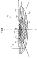
- FIG. 4 is a front view showing the lamp unit as a single article according to the first exemplary, non-limiting embodiment of the present invention.
- FIG. 5 is a perspective view showing a light distribution pattern formed from light illuminated forward from the lamp unit of the vehicle headlamp on a virtual vertical screen;
- FIG. 6 is a side cross-sectional view showing a lamp unit of a vehicle headlamp according to a second exemplary, non-limiting embodiment of the present invention as a single article;
- FIG. 7 is a plan cross-sectional view showing the lamp unit shown in FIG. 6 as a single article according to the second exemplary, non-limiting embodiment of the present invention.
- FIG. 8 is a perspective view showing a light distribution pattern formed from light illuminated forward from the lamp unit shown in FIG. 6 on the virtual vertical screen, according to the second exemplary, non-limiting embodiment of the present invention.
- FIG. 9 is a side cross-sectional view showing a lamp unit of a vehicle headlamp according to a third exemplary, non-limiting embodiment of the present invention as a single article;
- FIG. 10 is a perspective view showing a light distribution pattern formed from light illuminated forward from the lamp unit shown in FIG. 9 on the virtual vertical screen, according to the third exemplary, non-limiting embodiment of the present invention.
- FIG. 11 is a side cross-sectional view showing a lamp unit of a vehicle headlamp according to a fourth exemplary, non-limiting embodiment of the present invention as a single article;
- FIG. 12 is a front view showing the lamp unit shown in FIG. 11 as a single article, according to the fourth exemplary, non-limiting embodiment of the present invention.
- FIG. 13 is a perspective view showing a light distribution pattern formed from light illuminated forward from the lamp unit shown in FIG. 11 on the virtual vertical screen, according to the fourth exemplary, non-limiting embodiment of the present invention.
- FIG. 1 is a side cross-sectional view showing a vehicle headlamp 10 .
- the vehicle headlamp 10 is configured such that a lamp unit 20 having an optical axis Ax extending in a longitudinal direction of the vehicle is housed within a lamp chamber to allow tilt in a vertical direction and in a lateral direction by way of an aiming mechanism 50 .
- the lamp chamber is formed from a lamp body 12 , and a clear or translucent cover 14 disposed at a front end opening of the lamp body 12 .
- the lamp unit 20 is configured such that, after completion of aiming control by means of the aiming mechanism 50 , the optical axis Ax of the lamp unit 20 extends in the longitudinal direction of the vehicle.
- FIG. 2 is a side cross-sectional view showing the lamp unit 20 as a single article;
- FIG. 3 is a plan cross-sectional view showing the same; and
- FIG. 4 is a front view showing the same.
- the lamp unit 20 is a projector-type lamp unit configured to illuminate light for forming a high-beam light distribution pattern, and comprises a light source bulb 22 , a reflector 24 , an annular lens 26 , a projection lens 28 , and a holder 30 .
- the projection lens 28 is formed from a plano-convex lens having a convex surface serving as the front surface and a plane surface as the back surface, and is disposed on the optical axis Ax.
- the projection lens 28 is configured such that an image on a focal plane including a rear focal point F is projected forward as a reversed image thereof.
- An outer peripheral edge of the projection lens 28 is fixedly supported on the holder 30 .
- the holder 30 is formed from a substantially cylindrical member whose diameter is tapered-down rearward.
- the light source bulb 22 is a discharge lamp, such as a metal halide bulb, which employs a discharge light-emitting section as a light source 22 a , and is attached to a rear end portion of the reflector 24 while being inserted thereinto.
- the light source 22 a is configured as a linear light source extending on the optical axis Ax.
- the reflector 24 has a reflection surface 24 a for reflecting light from the light source bulb 22 forward and close to the optical axis Ax.
- the reflection surface 24 a has a substantially elliptic cross-sectional profile, and is configured such that the eccentricity of the ellipse gradually increases from a vertical cross section toward a horizontal cross section.
- the annular lens 26 is formed from a peripheral edge portion of a convex-meniscus lens, and disposed between the projection lens 28 and the reflector 24 along the outer peripheral edge of the projection lens 28 , around the entire circumference thereof.
- the inner peripheral edge of the annular lens 26 is fixedly supported on the holder 30
- the outer peripheral edge of the annular lens 26 is fixedly supported on the reflector 24 .
- an annular flange 24 b for supporting the annular lens 26 is formed on a front-end opening of the reflector 24 .
- the shape of a back surface 26 a of the annular lens 26 is formed into a spherical surface having its center at a luminescence center of the light source 22 a .
- the cross-sectional profile of a front surface 26 b of the annular lens 26 through the optical axis Ax is formed into a uniform curve around the entire circumference of the annular lens 26 to cause direct light emitted from the light source 22 a and having reached the front surface 26 b to exit as substantially parallel light along the optical axis Ax.
- FIG. 5 is a perspective view showing a high-beam light distribution pattern PH formed on a virtual vertical screen placed about 25 m a head of the lamp, by means of light illuminated forward from the lamp unit 20 of the first embodiment.
- the high-beam light distribution pattern PH is formed as a composite light distribution pattern consisting of a basic light distribution pattern P 01 and an additional light distribution pattern Pa 1 .
- the basic light distribution pattern P 01 is a light distribution pattern formed from light emitted from the light source 22 a , reflected from the reflector 24 , and having passed through the projection lens 28 , and is formed as a horizontally-elongated light distribution pattern widely extending in the horizontal direction with respect to a point H-V, which corresponds to a vanishing point ahead of the lamp. Accordingly, a hot zone HZ 1 , which is a high-intensity region, is formed so as to surround the point H-V.
- the additional light distribution pattern Pa 1 is a light distribution pattern formed from direct light emitted from the light source 22 a and having passed through the annular lens 26 .
- the additional light distribution pattern Pa 1 is configured as a spot-like circular light distribution pattern having its center at the point H-V.
- the vehicle headlamp 10 is configured such that the lamp unit 20 is a projector-type lamp unit that illuminates light for forming the high-beam light distribution pattern PH.
- the annular lens 26 formed from a peripheral edge portion of a convex-meniscus lens, is disposed between the projection lens 28 and the reflector 24 along the outer peripheral edge of the projection lens 28 . Accordingly, direct light from the light source 22 a toward the space beyond the outer periphery of the projection lens 28 can be caused to illuminate forward of the lamp by means of the annular lens 26 , thereby enabling effective utilization of light source luminous flux.
- brightness of the high-beam light distribution pattern PH can be enhanced when the additional light distribution pattern Pa 1 —formed from direct light emitted from the light source 22 a and having passed through the annular lens 26 —is added to the basic light distribution pattern P 01 —formed from light illuminated from the light source 22 a , reflected from the reflector 24 , and having passed through the projection lens 28 .
- the shape of the back surface of the annular lens 26 is a substantially spherical surface having its center at the luminescence center of the light source 22 a . Accordingly, direct light from the light source 22 a can be caused to travel straight without undergoing essential refraction on the back surface 26 a of the annular lens 26 . Consequently, a light deflection angle for causing direct light emitted from the light source and having reached the front surface 26 b to exit as substantially parallel light along the optical axis Ax can be calculated easily and with substantially high accuracy.
- annular lens 26 serving as an annular translucent member in the projector-type lamp unit 20 , light source luminous flux can be effectively utilized, and light deflection control by use of the annular lens 26 can be performed easily and with good accuracy.
- the cross-sectional profile of the front surface 26 b of the annular lens 26 through the optical axis Ax is a uniform curve around the entire circumference of the annular lens 26 , so as to cause direct light emitted from the light source 22 a and having reached the front surface 26 b to exit as substantially parallel light along the optical axis Ax.
- the additional light distribution pattern Pa 1 can be formed as a spot-like light distribution pattern a head of the lamp.
- the high-beam light distribution pattern PH can be enhanced in terms of the distant visibility of the road along which the vehicle drives.
- the holder 30 is disposed between the projection lens 28 and the annular lens 26 . Accordingly, incidence of direct light from the light source 22 a into the annular lens 26 as stray light is prevented.
- the first embodiment has been described on an assumption that the cross-sectional profile of the front surface 26 b of the annular lens 26 through the optical axis Ax is formed into a uniform curve around the entire circumference of the annular lens 26 .
- substantially the same working effects as those of the first embodiment can be obtained, so long as its cross sectional profile is formed into a substantially uniform curve around the entire circumference of the annular lens 26 .
- the first embodiment has been described on an assumption that the shape of the back surface of the annular lens 26 is a substantially spherical surface having its center at the luminescence center of the light source 22 a .
- substantially the same working effects as those of the first embodiment can be obtained, so long as the shape of the back surface of the annular lens 26 is formed into a curved surface which closely approximates that of the first embodiment.
- the first embodiment has been described on an assumption that the holder 30 is disposed between the projection lens 28 and the annular lens 26 .
- a configuration in which the projection lens 28 and the annular lens 26 are directly fixed to each other can also be adopted.
- FIG. 6 is a side cross-sectional view showing a lamp unit 120 of a vehicle headlamp according to the second embodiment as a single article.
- FIG. 7 is a plan cross-sectional view showing the same.
- the lamp unit 120 is a projector-type lamp unit configured to illuminate light for forming a low-beam light distribution pattern, and has a basic structure analogous to that of the first embodiment. However, the lamp unit differs from that of the first embodiment in that a shade 32 is added, and also in a focal length of the projection lens 28 , a shape of the reflection surface of the reflector 24 , and a shape of the front surface of the annular lens 26 .
- the shade 32 of the present embodiment is formed integrally with the holder 30 so as to extend rearward from a substantially lower half section of the holder 30 .
- the shade 32 is formed such that an upper edge 32 a thereof passes through the rear focal point F of the projection lens 28 . Accordingly, some of light reflected from the reflection surface 24 a of the reflector 24 is shielded, thereby removing most of upward light exiting forward from the projection lens 28 .
- the upper edge 32 a of the shade 32 extends horizontally as a substantially arc shape along a rear focal plane of the projection lens 28 such that the right-side and left-side of the edge differ from each other in level.
- the shade 32 is formed so as not to shield direct light from the light source 22 a toward the annular lens 26 .
- the focal length of the projection lens 28 of the second embodiment is formed into a value slightly larger than that of the first embodiment.
- a curvature of the vertical cross-sectional profile of the reflection surface 24 a of the reflector 24 of the second embodiment differs slightly from that of the first embodiment.
- the lamp unit 120 is configured such that, after completion of aiming control, the optical axis Ax extends in a direction oriented approximately 0.5 to 0.6° downward with respect to the longitudinal direction of the vehicle.
- the annular lens 26 of the second embodiment is set such that the cross-sectional profile of the front surface 26 b through the optical axis Ax varies depending on its circumferential position. Accordingly, direct light emitted from the light source 22 a and having reached the front surface 26 b is caused to emit as light oriented downward with respect to the optical axis Ax. More specifically, the annular lens 26 is set such that the light deflection angle assumes its highest value at the upper region located directly above the optical axis Ax, its lowest value at the lower region located directly under the optical axis Ax, and intermediate values at lateral regions located to the left and right sides of the optical axis Ax.
- the front surface 26 b of the annular lens 26 is set such that the curvature of a curve constituting the cross-sectional profile through the optical axis Ax slightly higher in the upper region as compared with that of the first embodiment, slightly lower in the lower region as compared with the first embodiment, and considerably lower in the lateral regions as compared with the first embodiment. Accordingly, the light having exited from the front surface 26 b is caused to converge at a certain distance in the vertical direction and thereafter slightly diffuse in the vertical direction in the upper region; in the lower region, to slightly diffuse in the vertical direction; and, in the lateral regions, to diffuse in the lateral direction to some extent.
- FIG. 8 is a perspective view showing a low-beam light distribution pattern PL formed from light illuminated forward from the lamp unit 120 of the present embodiment on the virtual vertical screen.
- the low-beam light distribution pattern PL is a left-oriented low-beam light distribution pattern and is formed as a composite light distribution pattern consisting of a basic light distribution pattern P 02 and an additional light distribution pattern Pa 2 .
- the basic light distribution pattern P 02 is a light distribution pattern formed from light emitted from the light source 22 a , reflected by the reflector 24 , and having passed through the projection lens 28 .
- the pattern P 02 has, at an upper edge thereof, cutoff lines CL 1 and CL 2 which differ in level on the right and the left sides thereof and which are formed as reverse projection images of the upper edge 32 a of the shade 32 .
- the cutoff lines CL 1 and CL 2 extend horizontally so as to differ in height on the right and the left sides with a line V—V vertically passing through the point H-V therebetween.
- the portion to the right of the line V—V and corresponding to the opposite lane is formed as the lower cutoff line CL 1
- the portion on the left of the line V—V and corresponding to the vehicle's own lane is formed as the upper cutoff line CL 2 .
- the upper cutoff line CL 2 is stepped-ascended from the lower cutoff line CL 1 with a tilted section therebetween.
- a position of an elbow point E which is an intersection of the lower cutoff line CL 1 and the line V—V, is formed into a location situated about 0.5 to 0.6° below the point H-V; and a hot zone HZ 2 , which is a high-intensity region, is formed so as to surround the elbow point E.
- the additional light distribution pattern Pa 2 is a light distribution pattern formed from direct light emitted from the light source 22 a and having passed through the annular lens 26 , and is configured as an oblate and substantially semicircular light distribution pattern which is diffused to the left and right sides of the line V—V at a certain diffusion angle and with the elbow point E as its center.
- the additional light distribution pattern Pa 2 is formed such that the upper edge thereof is located slightly below the lower cutoff line CL 1 .
- the annular lens 26 formed from a peripheral edge portion of a convex-meniscus lens, is disposed between the projection lens 28 and the reflector 24 along the outer peripheral edge of the projection lens 28 . Accordingly, direct light from the light source 22 a toward the space beyond the outer periphery of the projection lens 28 can be caused to illuminate forward of the lamp by means of the annular lens 26 , thereby enabling effective utilization of light source luminous flux.
- the back surface of the annular lens 26 is formed into a substantially spherical surface having its center at the luminescence center of the light source 22 a . Accordingly, direct light from the light source 22 a can be caused to travel straight without being deflected on the back surface 26 a of the annular lens 26 , whereby a light deflection angle on the front surface 26 b of the annular lens 26 can be calculated easily and with good accuracy.
- the cross-sectional profile of the front surface 26 b of the annular lens 26 through the optical axis Ax is formed into a curve whose shape varies depending on its circumferential position to thus cause direct light emitted from the light source 22 a and having reached the front surface 26 b to exit as light oriented downward with respect to the optical axis Ax. Therefore, the additional light distribution pattern Pa 2 can be formed so as not to extend above the cut-off lines CL 1 , CL 2 of the low-beam light distribution pattern PL.
- a projector-type lamp unit configured to illuminate light for forming a low-beam light distribution pattern
- the following concern may arise.
- forward-illuminated light from a vehicle shines directly into the eyes of the driver of an oncoming driver vehicle or others as a result of a vehicle changing its spatial orientation or the like, only a projection lens portion of the light appears to glow with high intensity.
- the driver of the oncoming vehicle or others experience glare.
- a peripheral portion of the projection lens 28 can appear relatively dim. Accordingly, contrast in brightness between the projection lens 28 and the peripheral portion thereof can be decreased, thereby enabling a substantial reduction in glare experienced by the driver of the oncoming vehicle or others.
- FIG. 9 is a side cross-sectional view showing a lamp unit 220 of a vehicle headlamp according to the third embodiment.
- the lamp unit 220 has a basic structure analogous to that of the second embodiment. However, the lamp unit differs from that of the second embodiment in the configuration of the annular lens 26 .
- an upward-illuminating lens section 26 c for orienting direct light from the light source 22 a upward with respect to the optical axis Ax is formed on an upper portion of the projection lens 28 of the annular lens 26 .
- the upward-illuminating lens section 26 c is formed by partially notching the back surface 26 a of the annular lens in a wedge shape.
- the upward-illuminating lens section 26 c partially decreases an optical deflecting effect of the annular lens 26 , thereby orienting slightly upward some of light having exited from the front surface 26 b of the annular lens 26 .
- FIG. 10 is a perspective view showing the low-beam light distribution pattern PL formed from light illuminated forward from the lamp unit 220 of the third embodiment on the virtual vertical screen.
- the low-beam light distribution pattern PL is analogous to that of the second embodiment with regard to the basic light distribution pattern P 02 .
- a portion of the additional light distribution pattern Pa 2 is formed as an overhead-sign-illuminating light distribution pattern Po.
- an overhead sign hereinafter, sometimes referred to as an “OHS” of a road ahead of the vehicle is illuminated, thereby ensuring the visibility of the OHS.
- the upward-illuminating lens section 26 c is formed by partially notching the back surface 26 a of the annular lens in a wedge shape, the overhead-sign-illuminating light distribution pattern Po can be formed without impairing the appearance of the annular lens 26 .
- FIG. 11 is a side cross-sectional view showing a lamp unit 320 of a vehicle headlamp according to the fourth embodiment as a single article.
- FIG. 12 is a front view showing the same.
- the lamp unit 320 has a basic structure analogous to that of the second embodiment. However, the configuration of the annular lens 26 differs from that of the second embodiment.
- annular lens 26 of the fourth embodiment is divided into two halves consisting of an upper half section 26 A and a lower half section 26 B.
- the surface shape of a back surface 26 Aa of the upper half section 26 A of the annular lens 26 is formed into a spherical surface having its center at a point A located ahead and in the vicinity of the light source 22 a .
- the surface shape of a back surface 26 Ba of the lower half section 26 B of the annular lens 26 is formed into a spherical surface having its center at a point B located to the rear and in the vicinity of the light source 22 a.
- the cross-sectional profile of a front surface 26 Ab of the upper half section 26 A of the annular lens 26 through the optical axis Ax is formed into a substantially uniform curve over the half circumference of the annular lens 26 corresponding to the upper half thereof, so as to cause virtual direct light from the point A and having reached the front surface 26 Ab to exit as parallel light along the optical axis Ax.
- the cross-sectional profile of a front surface 26 Bb of the lower half section 26 B of the annular lens 26 through the optical axis Ax is formed into a uniform curve over the half circumference of the annular lens 26 corresponding to the lower half thereof so as to cause virtual direct light from the point B and having reached the front surface 26 Bb to exit as parallel light along the optical axis Ax.
- FIG. 13 is a perspective view showing the low-beam light distribution pattern PL formed from light illuminated forward from the lamp unit 320 of the embodiment on the virtual vertical screen.
- the low-beam light distribution pattern PL is analogous to that of the second embodiment with regard to the basic light distribution pattern P 02 .
- the additional light distribution pattern is formed as a composite light distribution pattern including an additional light distribution pattern Pa 2 A formed from light having exited from the upper half section 26 A of the annular lens 26 and an additional light distribution pattern Pa 2 B formed from light having exited from the lower half section 26 B of the annular lens 26 .
- Each of the additional light distribution patterns Pa 2 A, Pa 2 B is formed as a spot-like light distribution pattern which is smaller than the additional light distribution pattern Pa 2 of the second embodiment, and reinforces brightness of the hot zone HZ 2 .
- brightness of the low-beam light distribution pattern PL can be enhanced by adding the additional light distribution patterns Pa 2 A, Pa 2 B—formed from light emitted from the light source 22 a and having passed through the annular lens 26 —to the basic light distribution pattern P 02 —formed from light illuminated from the light source 22 a , reflected from the reflector 24 , and having passed through the projection lens 28 .
- the surface shape of the back surface of the upper half section 26 A of the annular lens 26 is formed into a substantially spherical surface having its center at the point A located ahead and in the vicinity of the light source 22 a ; and the surface shape of the back surface of the lower half section 26 B of the annular lens 26 is formed into a substantially spherical surface having its center at the point B located to the rear and in the vicinity of the light source 22 a . Accordingly, all the light having exited from the annular lens can be formed as light oriented downward with respect to the optical axis Ax so as not to extend above the cut-off lines CL 1 , CL 2 of the low-beam light distribution pattern PL. When configured as above, occurrence of glare as a result of providing the annular lens 26 can be substantially prevented.
- each of the additional light distribution patterns Pa 2 A, Pa 2 B is formed as a spot-like light distribution pattern. Accordingly, brightness of the hot zone HZ 2 can be effectively reinforced.
- annular lens 26 is divided into two halves consisting of the upper half section 26 A and the lower half section 26 B, assembly of the annular lens 26 can be facilitated.
- the annular lens 26 is constituted of the upper half section 26 A and the lower half section 26 B having different shapes as in the present embodiment, manufacture of the annular lens 26 can be facilitated.
- annular lens 26 when the annular lens 26 is constituted of two halves consisting of the upper half section and the lower half section, assembly of the annular lens 26 can be facilitated.
- a configuration where the annular lens 26 is disposed at a portion in the circumferential direction of the outer periphery of the projection lens 28 can also be employed instead of the configuration where the annular lens 26 is disposed along the entire outer peripheral edge of the projection lens 28 .
Landscapes
- Engineering & Computer Science (AREA)
- General Engineering & Computer Science (AREA)
- Physics & Mathematics (AREA)
- General Physics & Mathematics (AREA)
- Optics & Photonics (AREA)
- Non-Portable Lighting Devices Or Systems Thereof (AREA)
Applications Claiming Priority (4)
| Application Number | Priority Date | Filing Date | Title |
|---|---|---|---|
| JPP.2004-052230 | 2004-02-26 | ||
| JP2004052230 | 2004-02-26 | ||
| JPP.2004-350695 | 2004-12-03 | ||
| JP2004350695A JP4205048B2 (ja) | 2004-02-26 | 2004-12-03 | 車両用前照灯 |
Publications (2)
| Publication Number | Publication Date |
|---|---|
| US20050190572A1 US20050190572A1 (en) | 2005-09-01 |
| US7168832B2 true US7168832B2 (en) | 2007-01-30 |
Family
ID=34889395
Family Applications (1)
| Application Number | Title | Priority Date | Filing Date |
|---|---|---|---|
| US11/063,893 Expired - Fee Related US7168832B2 (en) | 2004-02-26 | 2005-02-24 | Vehicle headlamp |
Country Status (3)
| Country | Link |
|---|---|
| US (1) | US7168832B2 (zh) |
| JP (1) | JP4205048B2 (zh) |
| CN (1) | CN100587320C (zh) |
Cited By (11)
| Publication number | Priority date | Publication date | Assignee | Title |
|---|---|---|---|---|
| US20050225995A1 (en) * | 2004-03-01 | 2005-10-13 | Koito Manufacturing Co., Ltd. | Vehicle headlamp |
| US20060262552A1 (en) * | 2005-05-18 | 2006-11-23 | Koito Manufacturing Co., Ltd. | Vehicle headlamp |
| US20070019428A1 (en) * | 2005-07-19 | 2007-01-25 | Koito Manufacturing Co., Ltd. | Vehicle lamp |
| US20090067186A1 (en) * | 2007-09-07 | 2009-03-12 | Takashi Futami | Vehicle lamp unit |
| US20090315479A1 (en) * | 2008-06-20 | 2009-12-24 | Koito Manufacturing Co., Ltd. | Vehicle head lamp apparatus |
| US20100135036A1 (en) * | 2008-12-02 | 2010-06-03 | Harison Toshiba Lighting Corp. | Vehicle lighting device |
| US20120075867A1 (en) * | 2010-09-27 | 2012-03-29 | Foxsemicon Integrated Technology, Inc. | Lens and light source module |
| US20130308330A1 (en) * | 2012-04-27 | 2013-11-21 | Koito Manufacturing Co., Ltd. | Lamp unit |
| US20150098236A1 (en) * | 2013-10-04 | 2015-04-09 | Tyc Brother Industrial Co., Ltd. | Optical structure for headlight |
| US20160238208A1 (en) * | 2015-02-17 | 2016-08-18 | Cheng Wang | Light distance-adjustable vehicle lamp device |
| US10139069B2 (en) * | 2014-12-24 | 2018-11-27 | Shanghai Koito Automotive Lamp Co., Ltd | Partially aluminized lens for automotive lamp |
Families Citing this family (34)
| Publication number | Priority date | Publication date | Assignee | Title |
|---|---|---|---|---|
| JP4612850B2 (ja) * | 2005-03-10 | 2011-01-12 | キヤノン株式会社 | 照明装置および撮影装置 |
| FR2883359B1 (fr) * | 2005-03-15 | 2007-05-11 | Valeo Vision Sa | Projecteur lumineux pour vehicule automobile, de faible encombrement |
| US7399106B2 (en) * | 2005-06-13 | 2008-07-15 | Toyota Motor Engineering & Manufacturing North America, Inc. | Lens optics used to reduce part deformation due to heat |
| US7410282B2 (en) * | 2005-10-25 | 2008-08-12 | Visteon Global Technologies, Inc. | Bi-functional headlight module |
| JP2007179993A (ja) * | 2005-12-28 | 2007-07-12 | Koito Mfg Co Ltd | 車両用前照灯 |
| JP4654928B2 (ja) * | 2006-02-02 | 2011-03-23 | 市光工業株式会社 | 車両用灯具 |
| JP2007213913A (ja) * | 2006-02-08 | 2007-08-23 | Lightscape Design Office:Kk | リフレクタ付ランプ |
| JP4717696B2 (ja) * | 2006-04-20 | 2011-07-06 | 株式会社小糸製作所 | 車両用前照灯の灯具ユニット |
| JP4795094B2 (ja) * | 2006-04-24 | 2011-10-19 | 株式会社小糸製作所 | 車両用前照灯 |
| FR2901012B1 (fr) * | 2006-05-12 | 2008-07-18 | Valeo Vision Sa | Module optique de projecteur pour vehicule automobile |
| JP4964753B2 (ja) * | 2007-12-12 | 2012-07-04 | 株式会社小糸製作所 | 車両用照明灯具 |
| CN101699134A (zh) * | 2008-04-30 | 2010-04-28 | 麦格纳国际公司 | 紧凑型高效光学器件 |
| DE102008045166A1 (de) * | 2008-08-30 | 2010-03-04 | Daimler Ag | Beleuchtungsvorrichtung für ein Fahrzeug |
| JP2012529154A (ja) | 2009-06-03 | 2012-11-15 | マテリアル ワークス, エルエルシー | ランプアセンブリおよび製造方法 |
| KR101091314B1 (ko) * | 2009-10-01 | 2011-12-07 | 주식회사 에스엘라이팅 | 측방 조사용 프로젝션 렌즈 및 이를 장착한 헤드램프 |
| US8845128B2 (en) | 2009-12-02 | 2014-09-30 | Michael F. Pickholz | Structural headlamp assemblies for vehicular applications |
| JP5711890B2 (ja) * | 2010-02-02 | 2015-05-07 | スタンレー電気株式会社 | 車両用前照灯 |
| CA2806160C (en) * | 2010-07-20 | 2018-08-28 | Magna International Inc. | Hybrid projector led low beam headlamp |
| JP5615669B2 (ja) * | 2010-11-05 | 2014-10-29 | 株式会社小糸製作所 | 車両用灯具 |
| CN102128404A (zh) * | 2011-01-14 | 2011-07-20 | 东莞市鼎聚光电有限公司 | 一种led汽车近光灯具 |
| CN102322603B (zh) * | 2011-06-02 | 2013-05-29 | 天津方合科技发展有限公司 | 近光带有明暗截止线的汽车前照灯led光学组件 |
| JP5883588B2 (ja) * | 2011-07-26 | 2016-03-15 | 株式会社小糸製作所 | 車輌用灯具 |
| JP6179070B2 (ja) * | 2012-03-30 | 2017-08-16 | 市光工業株式会社 | 車両用灯具 |
| WO2014208655A1 (ja) * | 2013-06-26 | 2014-12-31 | 市光工業株式会社 | 車両用灯具 |
| JP6277613B2 (ja) * | 2013-06-26 | 2018-02-14 | 市光工業株式会社 | 車両用灯具 |
| KR101683969B1 (ko) * | 2014-07-01 | 2016-12-08 | 현대자동차주식회사 | 차량용 등화 장치 |
| US20170167684A1 (en) * | 2015-12-11 | 2017-06-15 | Hyundai Motor Company | Lamp for vehicle |
| KR101928752B1 (ko) | 2015-12-28 | 2018-12-13 | 에스엘 주식회사 | 차량용 램프 |
| DE112017000365B4 (de) * | 2016-01-13 | 2020-12-17 | Mitsubishi Electric Corporation | Scheinwerfermodul mit zwei bzw. drei reflektierenden Oberflächen und zwei gekrümmten Emissionsoberflächen, und Scheinwerfervorrichtung mit solch einem Scheinwerfermodul |
| JP6757909B2 (ja) * | 2017-06-05 | 2020-09-23 | パナソニックIpマネジメント株式会社 | 照明装置および車両用前照灯 |
| US11226078B2 (en) * | 2018-04-23 | 2022-01-18 | Stanley Electric Co., Ltd. | Vehicular lamp fitting |
| CN111665485A (zh) * | 2019-03-07 | 2020-09-15 | 深圳市速腾聚创科技有限公司 | 激光雷达 |
| CN111609375A (zh) * | 2020-06-10 | 2020-09-01 | 财团法人车辆研究测试中心 | 头灯光学系统及其应用的灯具 |
| EP3974710A1 (de) * | 2020-09-25 | 2022-03-30 | ZKW Group GmbH | Beleuchtungsvorrichtung für einen kraftfahrzeugscheinwerfer |
Citations (3)
| Publication number | Priority date | Publication date | Assignee | Title |
|---|---|---|---|---|
| JPH0439137A (ja) | 1990-06-04 | 1992-02-10 | Yamaha Motor Co Ltd | プロジェクタランプ |
| JPH10223002A (ja) | 1997-02-06 | 1998-08-21 | Robert Bosch Gmbh | 投射原理に従った車両用前照灯 |
| US6220736B1 (en) * | 1997-07-10 | 2001-04-24 | Robert Bosch Gmbh | Headlight for a vehicle |
-
2004
- 2004-12-03 JP JP2004350695A patent/JP4205048B2/ja not_active Expired - Fee Related
-
2005
- 2005-02-24 US US11/063,893 patent/US7168832B2/en not_active Expired - Fee Related
- 2005-02-28 CN CN200510052517A patent/CN100587320C/zh not_active Expired - Fee Related
Patent Citations (3)
| Publication number | Priority date | Publication date | Assignee | Title |
|---|---|---|---|---|
| JPH0439137A (ja) | 1990-06-04 | 1992-02-10 | Yamaha Motor Co Ltd | プロジェクタランプ |
| JPH10223002A (ja) | 1997-02-06 | 1998-08-21 | Robert Bosch Gmbh | 投射原理に従った車両用前照灯 |
| US6220736B1 (en) * | 1997-07-10 | 2001-04-24 | Robert Bosch Gmbh | Headlight for a vehicle |
Cited By (18)
| Publication number | Priority date | Publication date | Assignee | Title |
|---|---|---|---|---|
| US7364332B2 (en) * | 2004-03-01 | 2008-04-29 | Koito Manufacturing Co., Ltd. | Vehicle headlamp |
| US20050225995A1 (en) * | 2004-03-01 | 2005-10-13 | Koito Manufacturing Co., Ltd. | Vehicle headlamp |
| US20060262552A1 (en) * | 2005-05-18 | 2006-11-23 | Koito Manufacturing Co., Ltd. | Vehicle headlamp |
| US7290909B2 (en) * | 2005-05-18 | 2007-11-06 | Koito Manufacturing Co., Ltd. | Vehicle headlamp |
| US20070019428A1 (en) * | 2005-07-19 | 2007-01-25 | Koito Manufacturing Co., Ltd. | Vehicle lamp |
| US7445366B2 (en) * | 2005-07-19 | 2008-11-04 | Koito Manufacturing Co., Ltd. | Vehicle lamp with auxiliary lens |
| US20090067186A1 (en) * | 2007-09-07 | 2009-03-12 | Takashi Futami | Vehicle lamp unit |
| US7997779B2 (en) | 2007-09-07 | 2011-08-16 | Stanley Electric Co., Ltd. | Vehicle lamp unit |
| US8552648B2 (en) * | 2008-06-20 | 2013-10-08 | Koito Manufacturing Co., Ltd. | Vehicle headlamp apparatus |
| US20090315479A1 (en) * | 2008-06-20 | 2009-12-24 | Koito Manufacturing Co., Ltd. | Vehicle head lamp apparatus |
| US20100135036A1 (en) * | 2008-12-02 | 2010-06-03 | Harison Toshiba Lighting Corp. | Vehicle lighting device |
| US20120075867A1 (en) * | 2010-09-27 | 2012-03-29 | Foxsemicon Integrated Technology, Inc. | Lens and light source module |
| US20130308330A1 (en) * | 2012-04-27 | 2013-11-21 | Koito Manufacturing Co., Ltd. | Lamp unit |
| US8920012B2 (en) * | 2012-04-27 | 2014-12-30 | Koito Manufacturing Co., Ltd. | Lamp unit |
| US20150098236A1 (en) * | 2013-10-04 | 2015-04-09 | Tyc Brother Industrial Co., Ltd. | Optical structure for headlight |
| US10139069B2 (en) * | 2014-12-24 | 2018-11-27 | Shanghai Koito Automotive Lamp Co., Ltd | Partially aluminized lens for automotive lamp |
| US20160238208A1 (en) * | 2015-02-17 | 2016-08-18 | Cheng Wang | Light distance-adjustable vehicle lamp device |
| US9982863B2 (en) * | 2015-02-17 | 2018-05-29 | Adi Optics Co., Ltd. | Light distance-adjustable vehicle lamp device |
Also Published As
| Publication number | Publication date |
|---|---|
| US20050190572A1 (en) | 2005-09-01 |
| CN1661275A (zh) | 2005-08-31 |
| CN100587320C (zh) | 2010-02-03 |
| JP2005276806A (ja) | 2005-10-06 |
| JP4205048B2 (ja) | 2009-01-07 |
Similar Documents
| Publication | Publication Date | Title |
|---|---|---|
| US7168832B2 (en) | Vehicle headlamp | |
| US7234852B2 (en) | Vehicle headlamp | |
| US7387417B2 (en) | Vehicular headlamp | |
| US7290909B2 (en) | Vehicle headlamp | |
| KR100824912B1 (ko) | 차량용 전조등 | |
| JP4391870B2 (ja) | 車両用照明灯具 | |
| KR100570480B1 (ko) | 차량용 전조등 | |
| US6416210B1 (en) | Headlamp for a vehicle | |
| US6494603B1 (en) | Headlamp for a vehicle | |
| JP5280074B2 (ja) | 車両用前照灯装置 | |
| JP4264319B2 (ja) | 車両用前照灯 | |
| US7281830B2 (en) | Vehicle headlamp and lamp unit | |
| US20020093827A1 (en) | Vehicle headlamp | |
| US7367703B2 (en) | Vehicle headlamp and lamp unit | |
| JP4536479B2 (ja) | 車両用前照灯 | |
| JP2005251435A (ja) | 車両用前照灯 | |
| JP2006079984A (ja) | 車両用前照灯 | |
| JP4531673B2 (ja) | 車両用前照灯 | |
| US9133998B2 (en) | Vehicular illumination lamp | |
| JP4459095B2 (ja) | 車両用ベンディングランプ | |
| JP5797099B2 (ja) | 車両用照明灯具 | |
| JP2008091262A (ja) | 車両用前照灯 | |
| JP2023044895A (ja) | 車両用灯具 | |
| JP2005347127A (ja) | 車両用前照灯 | |
| JP2006040786A (ja) | 車両用前照灯 |
Legal Events
| Date | Code | Title | Description |
|---|---|---|---|
| AS | Assignment |
Owner name: KOITO MANUFACTURING CO., LTD., JAPAN Free format text: ASSIGNMENT OF ASSIGNORS INTEREST;ASSIGNORS:KOMATSU, MOTOHIRO;KINOSHITA, MASAO;NAGANAWA, MASAHITO;AND OTHERS;REEL/FRAME:016340/0254 Effective date: 20050210 |
|
| FPAY | Fee payment |
Year of fee payment: 4 |
|
| FPAY | Fee payment |
Year of fee payment: 8 |
|
| FEPP | Fee payment procedure |
Free format text: MAINTENANCE FEE REMINDER MAILED (ORIGINAL EVENT CODE: REM.); ENTITY STATUS OF PATENT OWNER: LARGE ENTITY |
|
| LAPS | Lapse for failure to pay maintenance fees |
Free format text: PATENT EXPIRED FOR FAILURE TO PAY MAINTENANCE FEES (ORIGINAL EVENT CODE: EXP.); ENTITY STATUS OF PATENT OWNER: LARGE ENTITY |
|
| STCH | Information on status: patent discontinuation |
Free format text: PATENT EXPIRED DUE TO NONPAYMENT OF MAINTENANCE FEES UNDER 37 CFR 1.362 |
|
| FP | Lapsed due to failure to pay maintenance fee |
Effective date: 20190130 |