US7159859B2 - Pipe clamp with releasable clamp body - Google Patents
Pipe clamp with releasable clamp body Download PDFInfo
- Publication number
- US7159859B2 US7159859B2 US10/678,724 US67872403A US7159859B2 US 7159859 B2 US7159859 B2 US 7159859B2 US 67872403 A US67872403 A US 67872403A US 7159859 B2 US7159859 B2 US 7159859B2
- Authority
- US
- United States
- Prior art keywords
- support
- clamp body
- retainer
- clamp
- workpiece
- Prior art date
- Legal status (The legal status is an assumption and is not a legal conclusion. Google has not performed a legal analysis and makes no representation as to the accuracy of the status listed.)
- Expired - Lifetime, expires
Links
- 230000000903 blocking effect Effects 0.000 abstract description 2
- 238000000034 method Methods 0.000 description 7
- 230000000881 depressing effect Effects 0.000 description 3
- 230000000994 depressogenic effect Effects 0.000 description 2
- 238000013459 approach Methods 0.000 description 1
- 230000000452 restraining effect Effects 0.000 description 1
Images


Classifications
-
- B—PERFORMING OPERATIONS; TRANSPORTING
- B25—HAND TOOLS; PORTABLE POWER-DRIVEN TOOLS; MANIPULATORS
- B25B—TOOLS OR BENCH DEVICES NOT OTHERWISE PROVIDED FOR, FOR FASTENING, CONNECTING, DISENGAGING OR HOLDING
- B25B5/00—Clamps
- B25B5/06—Arrangements for positively actuating jaws
- B25B5/10—Arrangements for positively actuating jaws using screws
- B25B5/102—Arrangements for positively actuating jaws using screws with at least one jaw sliding along a bar
-
- B—PERFORMING OPERATIONS; TRANSPORTING
- B25—HAND TOOLS; PORTABLE POWER-DRIVEN TOOLS; MANIPULATORS
- B25B—TOOLS OR BENCH DEVICES NOT OTHERWISE PROVIDED FOR, FOR FASTENING, CONNECTING, DISENGAGING OR HOLDING
- B25B5/00—Clamps
- B25B5/06—Arrangements for positively actuating jaws
- B25B5/068—Arrangements for positively actuating jaws with at least one jaw sliding along a bar
-
- B—PERFORMING OPERATIONS; TRANSPORTING
- B25—HAND TOOLS; PORTABLE POWER-DRIVEN TOOLS; MANIPULATORS
- B25B—TOOLS OR BENCH DEVICES NOT OTHERWISE PROVIDED FOR, FOR FASTENING, CONNECTING, DISENGAGING OR HOLDING
- B25B5/00—Clamps
- B25B5/16—Details, e.g. jaws, jaw attachments
- B25B5/166—Slideways; Guiding and/or blocking means for jaws thereon
Definitions
- the present invention relates to clamps such as pipe clamps, and in particular to pipe clamps having a releasably attached clamp body restraining motion of the support past the end of the clamp body.
- Clamps such as bar clamps and pipe clamps have been widely used in a variety of forms.
- U.S. Pat. No. 5,775,680 to Sorensen et al. discloses a bar clamp with a retainer within a clamp body through which a threaded screw is fed.
- EP0274746A1 to Kloepfer et al. discloses a clamp with a jaw that has a spring-loaded tilt plate for securing a displaceably mounted jaw against a rail.
- One aspect of the present invention regards a clamp that includes a support having a first end and a second end and defining a support axis.
- a workpiece supporting element is mounted to the support and a clamp body releasably connected to the support through a channel formed in the clamp body wherein the first end is inserted into the channel.
- the clamp body includes a retainer movably mounted to the clamp body to engage the support selectively and thereby to hold the clamp body selectively against movement with respect to the support in at least a first direction along the support axis.
- the clamp body further includes a jaw mounted on the clamp body and opposing the workpiece supporting element and an end cap opposite the jaw on the clamp body wherein the clamp body is restrained from motion along the support axis towards the workpiece supporting element beyond the first end of the support.
- a clamp body is provided with a channel formed in the clamp body and a retainer is movably mounted in the clamp body.
- a jaw is mounted on the clamp body and an end cap blocking one end of the channel.
- a third aspect of the present invention regards a method for orienting a clamp body with respect to a support of a clamp.
- the method includes providing a clamp body and support unattached to one another and placing a retainer in the clamp body in a release position by depressing the retainer. Placing a channel of the clamp body and a first end of the support in substantial alignment, inserting the clamp body onto the support until the first end impinges on an end cap of the clamp body and placing the retainer in an inclined position by releasing the retainer so that the clamp body is attached to the support.
- a fourth aspect of the present invention regards a method for orienting a clamp body with respect to a support of a clamp by providing a support with a clamp body secured to the support.
- the method further includes placing a retainer in the clamp body in a release position by depressing the retainer. At the release position, the clamp body is moved in a first direction along the support but is prevented from moving in a direction opposite the first direction. Next, the clamp body is removed from the support.
- FIG. 1 is a right side view of a first embodiment of a pipe clamp with a retainer in an inclined position in accordance with the present invention
- FIG. 2 is a right side view of the pipe clamp of FIG. 1 with the retainer in a release position;
- FIG. 3A is a right side cross-sectional view of the clamp in FIG. 1 with the retainer in the inclined position;
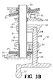
- FIG. 3B is a right side cross-sectional view of the clamp in FIG. 2 with the retainer in the inclined position;
- FIG. 4 is a right side perspective view of the clamp in FIG. 1 ;
- FIG. 5 is a second right side perspective view of the clamp in FIG. 1 ;
- FIG. 6 is an exploded view of the clamp in FIG. 1 .
- FIG. 1 shows an overall view of a clamp, such as a pipe clamp 10 which incorporates a first preferred embodiment of the present invention.
- the pipe clamp 10 includes a support 12 defining a support axis 14 and having a first end 16 and a second end 18 .
- the support 12 may have different cross-sectional shapes, such as an annulus if it is a pipe or a rectangle if it is a bar.
- Three components are slidably mounted on the support 12 : a clamp body 20 , a workpiece supporting element 22 , and a workpiece-engaging element 50 .
- the clamp body 20 is releasably connected to the support 12 through a channel 24 formed in the clamp body.
- the first end 16 of the support 12 is inserted into the channel 24 of the clamp body 20 .
- a retainer 26 is mounted to the clamp body 20 to engage the support 12 selectively and to hold the clamp body 20 selectively against movement with respect to the support 12 in at least a first direction A along the support axis 14 .
- An end cap 32 is present at an end of the clamp body 20 nearest the handle 52 .
- the retainer 26 may be embodied as one or more tabs 34 positioned around the support 12 .
- Each tab 34 includes a closed opening that generally corresponds to the cross-sectional shape of the support 12 .
- Each tab 34 is contained within clamp body 20 and has two ends 36 and 38 that extend through side openings 40 and 42 of the clamp body 20 .
- the tabs 34 are coupled to the clamp body 20 by a spring mechanism 44 (also see FIGS. 3A–B ) which is partially compressed when the retainer 26 is in the inclined position (in which the retainer 26 holds the clamp body 20 against movement along direction A with respect to the support 12 while allowing movement along direction B shown in FIG.
- the spring mechanism 44 preferably is a helical spring that has its longitudinal axis coinciding with the axis 14 . One end of the spring 44 contacts the interior wall of the end cap 32 while the other end of the spring contacts the retainer 26 .
- the clamp body 20 is attached to the workpiece supporting element 22 via a screw 48 .
- a portion of the screw 48 threadedly engages a threaded opening 49 of the clamp body.
- One end of the screw 48 is attached to a handle 52 while the other end of the screw 48 is connected to the workpiece supporting element 22 in a well known manner such as described in U.S. Pat. No. 5,775,680, the entire contents of which are incorporated herein by reference.
- the end of the screw 48 is inserted into an unthreaded opening 54 of the workpiece supporting element 22 .
- the workpiece supporting element 22 includes a second non–threaded opening 51 into which the support 12 is inserted.
- the workpiece supporting element 22 further includes a jaw 46 mounted thereon that faces an opposing jaw 28 of the workpiece engaging element 50 .
- the workpiece engaging element 50 operates in a manner similar to a like element disclosed in U.S. Pat. No. 5,775,680.
- the workpiece engaging element 50 includes a channel 53 that allows the support 12 to be inserted therethrough so that end 18 extends past the channel 53 .
- a spring mechanism such as the helical spring 55 , is positioned within the workpiece engaging element 50 so that its longitudinal axis coincides with axis 14 .
- One end of the spring 55 contacts the interior wall of the distal end of the workpiece engaging element 50 while the other end of the spring contacts the retainer 30 .
- the retainer 30 which includes tabs like tabs 34 , is biased by a spring 55 to engage the support 12 in a known manner.
- the retainer 30 prevents the workpiece engaging element 50 from movement along direction B with respect to the support 12 while at the same time allowing movement along direction A.
- the retainer 30 moves to the release position shown in FIG. 2 and allows the workpiece engaging element 50 to move along both directions A and B with respect to the support 12 .
- a method for attaching and removing a clamp body 20 to a support 12 and a method of clamping a workpiece is understood upon a review of FIGS. 1 and 2 .
- the support 12 is unattached to either of the clamp body 20 , the workpiece supporting element 22 and the workpiece engaging element 50 .
- the workpiece engaging element 50 is attached to the support 12 near end 18 in a well known manner.
- the end 16 of the support 12 is inserted through the opening 51 of the workpiece supporting element 22 and approaches the clamp body 20 .
- the retainer 26 Prior to the end 16 reaching the clamp body 20 , the retainer 26 is depressed until the retainer 26 is in a horizontal release position by depressing the retainer 26 (indicated by the arrow in FIG. 2 ).
- the retainer 26 may optionally not be depressed and be in the inclined position shown in FIG. 1 .
- the channel 24 of the clamp body 20 and the first end 16 of the support 12 are placed in substantial alignment.
- the clamp body 20 is inserted onto the support 12 until the first end 16 impinges on an end cap 32 of the clamp body 20 .
- the retainer 26 is placed in an inclined position (see FIG. 1 ) by releasing the retainer 26 so that the clamp body 20 is attached to the support 12 .
- the end cap 32 prevents the clamp body 20 from substantially moving along direction B while the retainer 26 prevents the clamp body 20 from moving along direction A.
- clamp body 20 and the workpiece supporting element 22 can be attached to the support 12 prior to attachment of the workpiece engaging element 50 to the support 12 .
- a workpiece W is placed against the jaw 28 of the workpiece engaging element 50 .
- the workpiece supporting element 22 is then moved along the support 12 towards the workpiece W by actuating the handle 52 of the screw 48 until the jaw 46 contacts the workpiece W. At this position, the workpiece W is held between the jaw 28 of the workpiece engaging element 50 and the jaw 46 of the workpiece supporting element 22 .
- the workpiece W is unclamped in three possible ways.
- the retainer 30 is moved to its horizontal release position as shown in FIG. 2 and the workpiece engaging element 50 is moved along direction B so that jaw 28 no longer contacts workpiece W.
- the handle 52 is turned so that workpiece supporting element 22 and its jaw 46 move along direction A so that the jaw 46 no longer contacts workpiece W.
- the retainer 26 is moved to its horizontal release position as shown in FIG. 2 and the clamp body 20 and the workpiece supporting element 22 move in unison along direction A so that jaw 46 no longer contacts workpiece W.
- the clamp body 20 and workpiece supporting element 22 are removed from the support 12 by continuing movement along direction A until end 16 is removed from the openings of the clamp body 20 and the workpiece supporting element 22 .
- the present invention can be used in a variety of bar clamps including pipe clamps.
- the workpiece supporting element 22 and the screw 48 can be removed and the jaw can be attached to the clamp body 20 .
- the clamp body is slid along the support 12 so as to have the jaw of the clamp body engage the workpiece.
Abstract
Description
Claims (12)
Priority Applications (5)
| Application Number | Priority Date | Filing Date | Title |
|---|---|---|---|
| US10/678,724 US7159859B2 (en) | 2003-10-03 | 2003-10-03 | Pipe clamp with releasable clamp body |
| PCT/US2004/032166 WO2005036040A2 (en) | 2003-10-03 | 2004-09-30 | Pipe clamp with relesable clamp body |
| CNB2004800358641A CN100411817C (en) | 2003-10-03 | 2004-09-30 | Pipe clamp with relesable clamp body |
| EP04789350A EP1668284B1 (en) | 2003-10-03 | 2004-09-30 | Pipe clamp with relesable clamp body |
| TW093129833A TWI283622B (en) | 2003-10-03 | 2004-10-01 | Pipe clamp with releasable clamp body |
Applications Claiming Priority (1)
| Application Number | Priority Date | Filing Date | Title |
|---|---|---|---|
| US10/678,724 US7159859B2 (en) | 2003-10-03 | 2003-10-03 | Pipe clamp with releasable clamp body |
Publications (2)
| Publication Number | Publication Date |
|---|---|
| US20050156368A1 US20050156368A1 (en) | 2005-07-21 |
| US7159859B2 true US7159859B2 (en) | 2007-01-09 |
Family
ID=34435364
Family Applications (1)
| Application Number | Title | Priority Date | Filing Date |
|---|---|---|---|
| US10/678,724 Expired - Lifetime US7159859B2 (en) | 2003-10-03 | 2003-10-03 | Pipe clamp with releasable clamp body |
Country Status (5)
| Country | Link |
|---|---|
| US (1) | US7159859B2 (en) |
| EP (1) | EP1668284B1 (en) |
| CN (1) | CN100411817C (en) |
| TW (1) | TWI283622B (en) |
| WO (1) | WO2005036040A2 (en) |
Cited By (13)
| Publication number | Priority date | Publication date | Assignee | Title |
|---|---|---|---|---|
| US20070007702A1 (en) * | 2005-06-08 | 2007-01-11 | Bernhard Brandl | Device and arrangement for fixing workpieces |
| US20070099460A1 (en) * | 2004-03-17 | 2007-05-03 | Guenter Holp | Tool for closing and separating pluggable quick acting closure couplings |
| US20070176342A1 (en) * | 2004-03-10 | 2007-08-02 | Wolfcraft, Gmbh | Single-handed clamp clip |
| US20090008850A1 (en) * | 2007-07-02 | 2009-01-08 | Ferng-Jong Liou | Quick clamping fixture |
| US20090283951A1 (en) * | 2008-05-13 | 2009-11-19 | Patrick Rowley | Clamp assembly |
| US20100327504A1 (en) * | 2009-06-28 | 2010-12-30 | Charles Seidel | Clamp Assembly |
| US20110101672A1 (en) * | 2008-06-02 | 2011-05-05 | Fredrik Bergling | Device for gripping an exhaust pipe |
| US20130122794A1 (en) * | 2011-11-15 | 2013-05-16 | Glen A. Edgar | Chimney tee cap retainer assembly |
| US9656184B1 (en) | 2016-03-23 | 2017-05-23 | Cristobal Castro | Sliding jump cup system, method and apparatus |
| USD824233S1 (en) | 2016-11-02 | 2018-07-31 | Lee Valley Tools Ltd. | Adjustable bench stop clamp |
| US10279455B1 (en) * | 2017-07-25 | 2019-05-07 | Royce D. Cooper | Pipe clamp |
| US10773362B2 (en) | 2016-02-15 | 2020-09-15 | Jeffrey E. Howard | Pivotable vise, clamping attachments for the vise, and related methods |
| US20220282802A1 (en) * | 2019-08-27 | 2022-09-08 | Orange | Clamping collar for keeping at least one network element on a post, associated positioning system and positioning method |
Families Citing this family (6)
| Publication number | Priority date | Publication date | Assignee | Title |
|---|---|---|---|---|
| US7322571B2 (en) * | 2005-11-23 | 2008-01-29 | Adjustable Clamp Company | Bar clamp |
| US20070222130A1 (en) * | 2006-03-23 | 2007-09-27 | Rockler Companies Incorporated | Quick release mechanism |
| CN103192331B (en) * | 2013-03-29 | 2014-12-17 | 江苏金通灵流体机械科技股份有限公司 | Adjustable locating assembly of marine engine partition plate or mechanical component |
| US8888084B1 (en) * | 2014-04-02 | 2014-11-18 | Robert L. Aldredge | Saw horse pipe clamp |
| US9283659B2 (en) * | 2014-04-18 | 2016-03-15 | Eugene Emerson | Straight edge bar clamp |
| CN104061842B (en) * | 2014-07-10 | 2017-02-15 | 中国重汽集团济南动力有限公司 | Stay wire tool for detecting vehicle framework waist rail and detecting method |
Citations (89)
| Publication number | Priority date | Publication date | Assignee | Title |
|---|---|---|---|---|
| US100642A (en) | 1870-03-08 | Improvement in clamps | ||
| US153206A (en) | 1874-07-21 | Improvement in joiners clamps | ||
| US226617A (en) | 1880-04-20 | konig- | ||
| US267152A (en) | 1882-11-07 | Assig-noe of one-half to | ||
| US404368A (en) | 1889-05-28 | stearns | ||
| US408473A (en) | 1889-08-06 | fockek | ||
| US410815A (en) | 1889-09-10 | Cabinet-clamp | ||
| US416096A (en) | 1889-11-26 | Can-lid holder | ||
| US491633A (en) | 1893-02-14 | Rassa | ||
| US678805A (en) | 1901-04-24 | 1901-07-16 | Paul A Weyand | Machinist's clamp. |
| US749732A (en) | 1904-01-19 | Consin | ||
| US757166A (en) | 1902-07-01 | 1904-04-12 | Karl Wintsch Jr | Bone-holding device. |
| US775659A (en) | 1904-03-09 | 1904-11-22 | Hans Jorgensen | Cabinet-maker's clamp. |
| US792758A (en) | 1904-01-07 | 1905-06-20 | Alva M Colt | Quick-acting clamp. |
| US927067A (en) | 1908-04-22 | 1909-07-06 | Abner W Offineer | Woodworker's clamp. |
| US934589A (en) | 1909-03-25 | 1909-09-21 | Charles E Bradford | Wrench. |
| US1241215A (en) | 1916-01-26 | 1917-09-25 | Louis Hoffman | Extension-clamp. |
| US1336755A (en) | 1915-08-06 | 1920-04-13 | Parmelee Roy | Vise |
| US1340092A (en) | 1919-12-22 | 1920-05-11 | Jr Adolf Tuscher | Pipe-wrench |
| US1393766A (en) | 1920-04-29 | 1921-10-18 | Charme William S Du | Portable pipe-vise stand |
| US1402621A (en) | 1919-10-06 | 1922-01-03 | Knittel Carl | Three-way clamp |
| US1450940A (en) | 1921-02-12 | 1923-04-10 | Isaac W Cobb | Door clamp |
| US1452753A (en) | 1922-03-09 | 1923-04-24 | William H Otto | Clamp |
| US1583611A (en) | 1924-08-26 | 1926-05-04 | Benjamin W Seely | Detachable extension clamp |
| US1639561A (en) | 1926-08-09 | 1927-08-16 | John M Hargrave | Clamp |
| US1783713A (en) | 1927-08-22 | 1930-12-02 | Adjustable Clamp Co | Adjustable clamp |
| US1811518A (en) | 1929-09-28 | 1931-06-23 | George E Palmer | Clamp |
| US1890042A (en) | 1929-09-27 | 1932-12-06 | Morandi Antonio | Clamping means |
| US2133892A (en) | 1937-08-09 | 1938-10-18 | Gelinski Paul | C-clamp type hand tool |
| US2157345A (en) | 1938-03-16 | 1939-05-09 | John W Nelson | Clamp |
| US2468358A (en) | 1945-03-09 | 1949-04-26 | Francis E Clark | Power drill holder |
| FR1019277A (en) | 1950-04-04 | 1953-01-20 | Further training in clamping devices such as clamps, vices and the like | |
| US2656864A (en) | 1949-04-21 | 1953-10-27 | Grand Specialties Company | Straight beam clamp with adjustable self-locking jaw |
| US2781803A (en) | 1953-09-23 | 1957-02-19 | John W Nelson | Cam actuated adjustable hold down clamp |
| US2815053A (en) | 1954-08-20 | 1957-12-03 | Walker Dunaway Hundley | Straight beam clamp with angularly adjustable clamping surfaces |
| US2815778A (en) | 1954-02-23 | 1957-12-10 | Adjustable Clamp Co | Straight beam adjustable jaw clamp |
| US2923334A (en) | 1958-06-17 | 1960-02-02 | Jr Charles M Brennan | Straight beam clamp with an adjustable self-locking jaw |
| US2949947A (en) | 1958-11-10 | 1960-08-23 | John D Story | Straight beam adjustable jaw clamp |
| US3033559A (en) | 1960-09-22 | 1962-05-08 | Edward J Lindholm | Clamp |
| AU225561A (en) | 1961-03-08 | 1963-03-14 | Rolls-Royce Limited | Heat exchange apparatus, e. g. for use in gas turbine engines |
| US3159393A (en) | 1963-02-11 | 1964-12-01 | Villano Joseph | Assembly insert holder |
| US3173674A (en) | 1962-03-23 | 1965-03-16 | Wilf S Day & Night Service | Universal compression safety clamp |
| US3218058A (en) * | 1964-02-17 | 1965-11-16 | Monogram Ind Inc | Quick adjustable clamp |
| US3331111A (en) | 1966-05-06 | 1967-07-18 | Carver & Co Eng | Clamps |
| US3499206A (en) | 1967-07-17 | 1970-03-10 | David E Quernheim | Attachment for bar clamp |
| US3575405A (en) | 1968-08-28 | 1971-04-20 | Emmit B Harding | Parallel bar clamping device |
| US3596898A (en) | 1969-03-07 | 1971-08-03 | Luell Hilburn | Fixture for welding pipes |
| US3806107A (en) | 1970-07-16 | 1974-04-23 | Adjustable Bushing Corp | Quick acting vise |
| US3914890A (en) | 1974-08-12 | 1975-10-28 | Jr C Fred Behlen | Vertically moveable multi panel sign |
| US3933346A (en) | 1973-04-17 | 1976-01-20 | Carver & Co. (Engineers) | Clamping or gripping devices |
| US3963230A (en) | 1974-11-11 | 1976-06-15 | Jankowski Jr John J | Stud and beam clamp |
| DE2539613A1 (en) | 1975-09-05 | 1977-03-10 | Bessey & Sohn | Clamping system for workpiece on wood workbench - has two clamping jaws movable along guide rail which is screw-mounted to holders on bench |
| US4078781A (en) | 1976-12-07 | 1978-03-14 | Hmc-Brauer Limited | Clamps |
| US4083548A (en) | 1976-11-11 | 1978-04-11 | Hackbarth Dale J | Adjustable clamp |
| US4088313A (en) | 1977-04-19 | 1978-05-09 | Pearson Hilding A | Spring actuated woodworking clamp |
| US4132397A (en) | 1977-08-22 | 1979-01-02 | Emerson Ward | Mounting bracket for a pipe clamp |
| US4143869A (en) | 1977-10-24 | 1979-03-13 | Paterson Roy A | Adjustment clamp |
| USD259327S (en) | 1978-11-16 | 1981-05-26 | Irving Sloane | Woodworking clamp |
| US4306710A (en) | 1980-08-28 | 1981-12-22 | Vosper George W | Bar type jack having jaw extensions removably attached thereto |
| US4339113A (en) | 1979-07-25 | 1982-07-13 | Vosper George W | Screw operated jack |
| US4381105A (en) | 1980-05-08 | 1983-04-26 | Gordon W. Hueschen | Clamp |
| DE3347232A1 (en) | 1983-12-28 | 1985-07-11 | Arthur Rinke & Söhne, Werkzeugfabrik, vorm. Langensiepen, GmbH & Co, 5630 Remscheid | Screw clamp |
| US4563921A (en) | 1985-03-05 | 1986-01-14 | John Wallace | Compact pliers with large, adjustable jaw span |
| USD286369S (en) | 1983-06-06 | 1986-10-28 | Hahn Manufacturing Co. | Clamp |
| DE8705546U1 (en) | 1987-04-14 | 1987-05-27 | Herba Werkzeugfabrik Max Herbstrith Gmbh & Co Kg, 5630 Remscheid, De | |
| EP0274746A1 (en) | 1987-01-15 | 1988-07-20 | Bessey & Sohn GmbH & Co. | Clamp with adjustable jaws |
| US4874155A (en) | 1988-09-09 | 1989-10-17 | Goul Ashley S | Fast clamp |
| US4893801A (en) | 1988-12-16 | 1990-01-16 | Flinn Robert W | Clamp |
| US4926722A (en) | 1988-08-19 | 1990-05-22 | Petersen Manufacturing Co., Inc. | Quick-action bar clamp |
| US4989847A (en) | 1989-09-12 | 1991-02-05 | Grant Chapman | Clamping device |
| US5058870A (en) | 1990-08-07 | 1991-10-22 | Cetnar Raymond P | Clamping apparatus |
| US5064178A (en) | 1990-04-16 | 1991-11-12 | Warren Tool Corporation | Mitered face for the jaws of a clamp, and a clamp employing a mitered face |
| US5094131A (en) | 1990-02-14 | 1992-03-10 | Petersen Manufacturing Co., Inc. | Hand tool or improved bar clamp |
| US5096170A (en) | 1990-08-23 | 1992-03-17 | Albin Stephen D | Clamp for picture frame tool and other purposes |
| US5156508A (en) | 1989-12-27 | 1992-10-20 | Grisley Kenneth M | Cam action clamp |
| US5161787A (en) | 1991-11-08 | 1992-11-10 | Hobday Harold W | Clamping device |
| USD333963S (en) | 1990-07-18 | 1993-03-16 | Robert Goodman | Hydraulic vise |
| US5197360A (en) | 1992-02-28 | 1993-03-30 | Adjustable Clamp Co. | Adjustable clamp |
| US5222420A (en) | 1988-08-19 | 1993-06-29 | Petersen Manufacturing Co., Inc. | Quick action bar clamp |
| USD340632S (en) | 1991-04-08 | 1993-10-26 | Easley David G | Woodcarving vise |
| USD346942S (en) | 1993-03-15 | 1994-05-17 | Btm Corporation | Plastic clamp |
| US5346194A (en) | 1993-07-07 | 1994-09-13 | Mapletek Engineering, Inc. | Adjustable clamp |
| USD355104S (en) | 1994-01-06 | 1995-02-07 | Petersen Manufacturing Co., Inc. | Pipe clamp |
| US5443246A (en) * | 1993-11-30 | 1995-08-22 | Peterson; Donovan J. | Clamp jaw extender for bar clamps |
| US5454551A (en) | 1993-11-10 | 1995-10-03 | Hobday Clamp Company | Clamping device |
| USD365263S (en) | 1994-06-27 | 1995-12-19 | Sorensen Joseph A | Pipe clamp |
| US5692734A (en) | 1993-07-15 | 1997-12-02 | American Tool Companies, Inc. | Clamp structure |
| US5775680A (en) * | 1994-07-27 | 1998-07-07 | Petersen Manufacturing, Inc. | Clamp with inclined screw |
| US20010006270A1 (en) | 1997-01-23 | 2001-07-05 | Baculy | Clamp fixtures |
Family Cites Families (9)
| Publication number | Priority date | Publication date | Assignee | Title |
|---|---|---|---|---|
| US1543197A (en) * | 1924-12-01 | 1925-06-23 | Christian D Ulrich | Expansible clamp |
| BE651157A (en) * | 1964-07-29 | 1964-11-16 | ||
| DE2149012A1 (en) * | 1970-10-01 | 1972-04-06 | Bolton Mining Eng | Clamping tool |
| US3914830A (en) * | 1974-02-08 | 1975-10-28 | Robert Benjamin Bolton | Tools having locking adjustments |
| US4042264A (en) * | 1976-01-12 | 1977-08-16 | Shumer James E | Clamping apparatus |
| GR1000944B (en) * | 1990-02-08 | 1993-03-16 | Alexandros Michalas | Rectilinear rapid fitting clamp |
| DE19731579A1 (en) * | 1997-07-23 | 1999-01-28 | Wolfcraft Gmbh | Clamping tool, especially clamp, vice or table |
| CN2361437Y (en) * | 1999-03-08 | 2000-02-02 | 游炎征 | Quick-clamping vice |
| CN2507613Y (en) * | 2001-10-25 | 2002-08-28 | 飞辅实业股份有限公司 | Single-handle fixed C-type gripping tool |
-
2003
- 2003-10-03 US US10/678,724 patent/US7159859B2/en not_active Expired - Lifetime
-
2004
- 2004-09-30 WO PCT/US2004/032166 patent/WO2005036040A2/en active Application Filing
- 2004-09-30 CN CNB2004800358641A patent/CN100411817C/en not_active Expired - Fee Related
- 2004-09-30 EP EP04789350A patent/EP1668284B1/en not_active Expired - Fee Related
- 2004-10-01 TW TW093129833A patent/TWI283622B/en not_active IP Right Cessation
Patent Citations (90)
| Publication number | Priority date | Publication date | Assignee | Title |
|---|---|---|---|---|
| US100642A (en) | 1870-03-08 | Improvement in clamps | ||
| US153206A (en) | 1874-07-21 | Improvement in joiners clamps | ||
| US226617A (en) | 1880-04-20 | konig- | ||
| US267152A (en) | 1882-11-07 | Assig-noe of one-half to | ||
| US404368A (en) | 1889-05-28 | stearns | ||
| US408473A (en) | 1889-08-06 | fockek | ||
| US410815A (en) | 1889-09-10 | Cabinet-clamp | ||
| US416096A (en) | 1889-11-26 | Can-lid holder | ||
| US491633A (en) | 1893-02-14 | Rassa | ||
| US749732A (en) | 1904-01-19 | Consin | ||
| US678805A (en) | 1901-04-24 | 1901-07-16 | Paul A Weyand | Machinist's clamp. |
| US757166A (en) | 1902-07-01 | 1904-04-12 | Karl Wintsch Jr | Bone-holding device. |
| US792758A (en) | 1904-01-07 | 1905-06-20 | Alva M Colt | Quick-acting clamp. |
| US775659A (en) | 1904-03-09 | 1904-11-22 | Hans Jorgensen | Cabinet-maker's clamp. |
| US927067A (en) | 1908-04-22 | 1909-07-06 | Abner W Offineer | Woodworker's clamp. |
| US934589A (en) | 1909-03-25 | 1909-09-21 | Charles E Bradford | Wrench. |
| US1336755A (en) | 1915-08-06 | 1920-04-13 | Parmelee Roy | Vise |
| US1241215A (en) | 1916-01-26 | 1917-09-25 | Louis Hoffman | Extension-clamp. |
| US1402621A (en) | 1919-10-06 | 1922-01-03 | Knittel Carl | Three-way clamp |
| US1340092A (en) | 1919-12-22 | 1920-05-11 | Jr Adolf Tuscher | Pipe-wrench |
| US1393766A (en) | 1920-04-29 | 1921-10-18 | Charme William S Du | Portable pipe-vise stand |
| US1450940A (en) | 1921-02-12 | 1923-04-10 | Isaac W Cobb | Door clamp |
| US1452753A (en) | 1922-03-09 | 1923-04-24 | William H Otto | Clamp |
| US1583611A (en) | 1924-08-26 | 1926-05-04 | Benjamin W Seely | Detachable extension clamp |
| US1639561A (en) | 1926-08-09 | 1927-08-16 | John M Hargrave | Clamp |
| US1783713A (en) | 1927-08-22 | 1930-12-02 | Adjustable Clamp Co | Adjustable clamp |
| US1890042A (en) | 1929-09-27 | 1932-12-06 | Morandi Antonio | Clamping means |
| US1811518A (en) | 1929-09-28 | 1931-06-23 | George E Palmer | Clamp |
| US2133892A (en) | 1937-08-09 | 1938-10-18 | Gelinski Paul | C-clamp type hand tool |
| US2157345A (en) | 1938-03-16 | 1939-05-09 | John W Nelson | Clamp |
| US2468358A (en) | 1945-03-09 | 1949-04-26 | Francis E Clark | Power drill holder |
| US2656864A (en) | 1949-04-21 | 1953-10-27 | Grand Specialties Company | Straight beam clamp with adjustable self-locking jaw |
| FR1019277A (en) | 1950-04-04 | 1953-01-20 | Further training in clamping devices such as clamps, vices and the like | |
| US2781803A (en) | 1953-09-23 | 1957-02-19 | John W Nelson | Cam actuated adjustable hold down clamp |
| US2815778A (en) | 1954-02-23 | 1957-12-10 | Adjustable Clamp Co | Straight beam adjustable jaw clamp |
| US2815053A (en) | 1954-08-20 | 1957-12-03 | Walker Dunaway Hundley | Straight beam clamp with angularly adjustable clamping surfaces |
| US2923334A (en) | 1958-06-17 | 1960-02-02 | Jr Charles M Brennan | Straight beam clamp with an adjustable self-locking jaw |
| US2949947A (en) | 1958-11-10 | 1960-08-23 | John D Story | Straight beam adjustable jaw clamp |
| US3033559A (en) | 1960-09-22 | 1962-05-08 | Edward J Lindholm | Clamp |
| AU225561A (en) | 1961-03-08 | 1963-03-14 | Rolls-Royce Limited | Heat exchange apparatus, e. g. for use in gas turbine engines |
| US3173674A (en) | 1962-03-23 | 1965-03-16 | Wilf S Day & Night Service | Universal compression safety clamp |
| US3159393A (en) | 1963-02-11 | 1964-12-01 | Villano Joseph | Assembly insert holder |
| US3218058A (en) * | 1964-02-17 | 1965-11-16 | Monogram Ind Inc | Quick adjustable clamp |
| US3331111A (en) | 1966-05-06 | 1967-07-18 | Carver & Co Eng | Clamps |
| US3499206A (en) | 1967-07-17 | 1970-03-10 | David E Quernheim | Attachment for bar clamp |
| US3575405A (en) | 1968-08-28 | 1971-04-20 | Emmit B Harding | Parallel bar clamping device |
| US3596898A (en) | 1969-03-07 | 1971-08-03 | Luell Hilburn | Fixture for welding pipes |
| US3806107A (en) | 1970-07-16 | 1974-04-23 | Adjustable Bushing Corp | Quick acting vise |
| US3933346A (en) | 1973-04-17 | 1976-01-20 | Carver & Co. (Engineers) | Clamping or gripping devices |
| US3914890A (en) | 1974-08-12 | 1975-10-28 | Jr C Fred Behlen | Vertically moveable multi panel sign |
| US3963230A (en) | 1974-11-11 | 1976-06-15 | Jankowski Jr John J | Stud and beam clamp |
| DE2539613A1 (en) | 1975-09-05 | 1977-03-10 | Bessey & Sohn | Clamping system for workpiece on wood workbench - has two clamping jaws movable along guide rail which is screw-mounted to holders on bench |
| US4083548A (en) | 1976-11-11 | 1978-04-11 | Hackbarth Dale J | Adjustable clamp |
| US4078781A (en) | 1976-12-07 | 1978-03-14 | Hmc-Brauer Limited | Clamps |
| US4088313A (en) | 1977-04-19 | 1978-05-09 | Pearson Hilding A | Spring actuated woodworking clamp |
| US4132397A (en) | 1977-08-22 | 1979-01-02 | Emerson Ward | Mounting bracket for a pipe clamp |
| US4143869A (en) | 1977-10-24 | 1979-03-13 | Paterson Roy A | Adjustment clamp |
| USD259327S (en) | 1978-11-16 | 1981-05-26 | Irving Sloane | Woodworking clamp |
| US4339113A (en) | 1979-07-25 | 1982-07-13 | Vosper George W | Screw operated jack |
| US4381105A (en) | 1980-05-08 | 1983-04-26 | Gordon W. Hueschen | Clamp |
| US4306710A (en) | 1980-08-28 | 1981-12-22 | Vosper George W | Bar type jack having jaw extensions removably attached thereto |
| USD286369S (en) | 1983-06-06 | 1986-10-28 | Hahn Manufacturing Co. | Clamp |
| DE3347232A1 (en) | 1983-12-28 | 1985-07-11 | Arthur Rinke & Söhne, Werkzeugfabrik, vorm. Langensiepen, GmbH & Co, 5630 Remscheid | Screw clamp |
| US4563921A (en) | 1985-03-05 | 1986-01-14 | John Wallace | Compact pliers with large, adjustable jaw span |
| EP0274746A1 (en) | 1987-01-15 | 1988-07-20 | Bessey & Sohn GmbH & Co. | Clamp with adjustable jaws |
| DE8705546U1 (en) | 1987-04-14 | 1987-05-27 | Herba Werkzeugfabrik Max Herbstrith Gmbh & Co Kg, 5630 Remscheid, De | |
| US5009134A (en) | 1988-08-19 | 1991-04-23 | Petersen Manufacturing Co., Inc. | Quick-action bar clamp |
| US4926722A (en) | 1988-08-19 | 1990-05-22 | Petersen Manufacturing Co., Inc. | Quick-action bar clamp |
| US5222420A (en) | 1988-08-19 | 1993-06-29 | Petersen Manufacturing Co., Inc. | Quick action bar clamp |
| US4874155A (en) | 1988-09-09 | 1989-10-17 | Goul Ashley S | Fast clamp |
| US4893801A (en) | 1988-12-16 | 1990-01-16 | Flinn Robert W | Clamp |
| US4989847A (en) | 1989-09-12 | 1991-02-05 | Grant Chapman | Clamping device |
| US5156508A (en) | 1989-12-27 | 1992-10-20 | Grisley Kenneth M | Cam action clamp |
| US5094131A (en) | 1990-02-14 | 1992-03-10 | Petersen Manufacturing Co., Inc. | Hand tool or improved bar clamp |
| US5064178A (en) | 1990-04-16 | 1991-11-12 | Warren Tool Corporation | Mitered face for the jaws of a clamp, and a clamp employing a mitered face |
| USD333963S (en) | 1990-07-18 | 1993-03-16 | Robert Goodman | Hydraulic vise |
| US5058870A (en) | 1990-08-07 | 1991-10-22 | Cetnar Raymond P | Clamping apparatus |
| US5096170A (en) | 1990-08-23 | 1992-03-17 | Albin Stephen D | Clamp for picture frame tool and other purposes |
| USD340632S (en) | 1991-04-08 | 1993-10-26 | Easley David G | Woodcarving vise |
| US5161787A (en) | 1991-11-08 | 1992-11-10 | Hobday Harold W | Clamping device |
| US5197360A (en) | 1992-02-28 | 1993-03-30 | Adjustable Clamp Co. | Adjustable clamp |
| USD346942S (en) | 1993-03-15 | 1994-05-17 | Btm Corporation | Plastic clamp |
| US5346194A (en) | 1993-07-07 | 1994-09-13 | Mapletek Engineering, Inc. | Adjustable clamp |
| US5692734A (en) | 1993-07-15 | 1997-12-02 | American Tool Companies, Inc. | Clamp structure |
| US5454551A (en) | 1993-11-10 | 1995-10-03 | Hobday Clamp Company | Clamping device |
| US5443246A (en) * | 1993-11-30 | 1995-08-22 | Peterson; Donovan J. | Clamp jaw extender for bar clamps |
| USD355104S (en) | 1994-01-06 | 1995-02-07 | Petersen Manufacturing Co., Inc. | Pipe clamp |
| USD365263S (en) | 1994-06-27 | 1995-12-19 | Sorensen Joseph A | Pipe clamp |
| US5775680A (en) * | 1994-07-27 | 1998-07-07 | Petersen Manufacturing, Inc. | Clamp with inclined screw |
| US20010006270A1 (en) | 1997-01-23 | 2001-07-05 | Baculy | Clamp fixtures |
Non-Patent Citations (9)
| Title |
|---|
| "Enco Precision Ground Milling Machine Vises" Publication source and date unknown. Two pages. It is believed that this publication was available to the public prior to Oct. 3, 2002. |
| "Handy Quick Clamp Manual" Publication source and date unknown. Four pages. It is believed that this publication was available to the public prior to Oct. 3, 2002. |
| "Pony Clamp Fixtures" styles 50, 52, 53 and 56. "Jorgensen Style 3500 Aluminum Bar Clamps." "Jorgensen Style 7200 Steel I-Bar Clamps." Publication source and date unknown. One page. It is believed that this publication was available to the public prior to Oct. 3, 2002. |
| "Pony Steel Bar Clamp Fixtures" styles 50, 52 and 56. Publication source and date unknown. One page. It is believed that this publication was available to the public prior to Oct. 3, 2002. |
| Advertisement for Bessey Bar Clamps Styles 52, 53 and 56. Publication source and date unknown. One page. It is believed that this publication was available to the public prior to Oct. 3, 2002. |
| Advertisement for Gross Stabil Clamp and Bessey Bar Clamps Styles 43 and 45. Publication source and date unknown. One page. It is believed that this publication was available to the public prior to Oct. 3, 2002. |
| Bessey Steel Bar Clamp Fixture RS 75 instructions. Publication source and date unknown. Two pages. It is believed that this publication was available to the public prior to Oct. 3, 2002. |
| PCT International Preliminary Report on Patentability dated May 4, 2006. |
| PCT International Search Report for PCT/US04/32166 dated Mar. 28, 2006. |
Cited By (16)
| Publication number | Priority date | Publication date | Assignee | Title |
|---|---|---|---|---|
| US20070176342A1 (en) * | 2004-03-10 | 2007-08-02 | Wolfcraft, Gmbh | Single-handed clamp clip |
| US20070099460A1 (en) * | 2004-03-17 | 2007-05-03 | Guenter Holp | Tool for closing and separating pluggable quick acting closure couplings |
| US20070007702A1 (en) * | 2005-06-08 | 2007-01-11 | Bernhard Brandl | Device and arrangement for fixing workpieces |
| US20090008850A1 (en) * | 2007-07-02 | 2009-01-08 | Ferng-Jong Liou | Quick clamping fixture |
| US7600744B2 (en) * | 2007-07-02 | 2009-10-13 | Ferng Jong Liou | Quick clamping fixture |
| US20090283951A1 (en) * | 2008-05-13 | 2009-11-19 | Patrick Rowley | Clamp assembly |
| US20110101672A1 (en) * | 2008-06-02 | 2011-05-05 | Fredrik Bergling | Device for gripping an exhaust pipe |
| US20100327504A1 (en) * | 2009-06-28 | 2010-12-30 | Charles Seidel | Clamp Assembly |
| US20130122794A1 (en) * | 2011-11-15 | 2013-05-16 | Glen A. Edgar | Chimney tee cap retainer assembly |
| US9605848B2 (en) * | 2011-11-15 | 2017-03-28 | Selkirk Corporation | Chimney tee cap retainer assembly |
| US10773362B2 (en) | 2016-02-15 | 2020-09-15 | Jeffrey E. Howard | Pivotable vise, clamping attachments for the vise, and related methods |
| US9656184B1 (en) | 2016-03-23 | 2017-05-23 | Cristobal Castro | Sliding jump cup system, method and apparatus |
| USD824233S1 (en) | 2016-11-02 | 2018-07-31 | Lee Valley Tools Ltd. | Adjustable bench stop clamp |
| US10279455B1 (en) * | 2017-07-25 | 2019-05-07 | Royce D. Cooper | Pipe clamp |
| US20220282802A1 (en) * | 2019-08-27 | 2022-09-08 | Orange | Clamping collar for keeping at least one network element on a post, associated positioning system and positioning method |
| US11754202B2 (en) * | 2019-08-27 | 2023-09-12 | Orange | Clamping collar for keeping at least one net work element on a post, associated positioning system and positioning method |
Also Published As
| Publication number | Publication date |
|---|---|
| CN100411817C (en) | 2008-08-20 |
| CN1890056A (en) | 2007-01-03 |
| WO2005036040A2 (en) | 2005-04-21 |
| TW200517222A (en) | 2005-06-01 |
| EP1668284A4 (en) | 2009-12-30 |
| US20050156368A1 (en) | 2005-07-21 |
| TWI283622B (en) | 2007-07-11 |
| EP1668284A2 (en) | 2006-06-14 |
| EP1668284B1 (en) | 2012-11-14 |
| WO2005036040A3 (en) | 2006-05-26 |
Similar Documents
| Publication | Publication Date | Title |
|---|---|---|
| US7159859B2 (en) | Pipe clamp with releasable clamp body | |
| US5913509A (en) | Clamp for a power tool | |
| US8827255B2 (en) | Clamp assembly | |
| KR100326794B1 (en) | Adjustable clamping jaw | |
| US4893801A (en) | Clamp | |
| US6848683B2 (en) | Arm clamp | |
| US8302921B2 (en) | Surgical appliance post clamp for surgical tables | |
| US4241906A (en) | Ski vise | |
| WO2002094086A3 (en) | Retractor clamp assembly | |
| US6568667B1 (en) | Quick setup apparatus for bar clamp operated with one hand | |
| US20030071402A1 (en) | Vise system | |
| WO2004054408B1 (en) | Bed rail | |
| EP0099704A3 (en) | Device for clamping workpieces | |
| US20060049563A1 (en) | Extension device for a clamping and spreading device and clamping and spreading device | |
| JP2006341333A (en) | Locating clamp device | |
| US20070090580A1 (en) | Adjustable clamp system | |
| EP0702192A1 (en) | A clamp for supporting optical and photographic equipment | |
| US20090302518A1 (en) | Portable Clamp | |
| US6334609B1 (en) | Quick clamp and release vise | |
| US6553851B1 (en) | Exit sign and emergency light testing-clamp | |
| WO1988007434A1 (en) | Holders | |
| CA2357769C (en) | Workpiece vice holding system | |
| EP0272122A2 (en) | Improvement in the vice (6) | |
| WO2006117619A3 (en) | A surgical support arm | |
| EP0953479A3 (en) | Support |
Legal Events
| Date | Code | Title | Description |
|---|---|---|---|
| AS | Assignment |
Owner name: IRWIN INDUSTRIAL TOOL COMPANY, NORTH CAROLINA Free format text: ASSIGNMENT OF ASSIGNORS INTEREST;ASSIGNOR:FULLER, ANTHONY B.;REEL/FRAME:015324/0939 Effective date: 20041101 |
|
| STCF | Information on status: patent grant |
Free format text: PATENTED CASE |
|
| FPAY | Fee payment |
Year of fee payment: 4 |
|
| FPAY | Fee payment |
Year of fee payment: 8 |
|
| MAFP | Maintenance fee payment |
Free format text: PAYMENT OF MAINTENANCE FEE, 12TH YEAR, LARGE ENTITY (ORIGINAL EVENT CODE: M1553) Year of fee payment: 12 |
|
| AS | Assignment |
Owner name: BLACK & DECKER INC., CONNECTICUT Free format text: ASSIGNMENT OF ASSIGNORS INTEREST;ASSIGNOR:IRWIN INDUSTRIAL TOOL COMPANY;REEL/FRAME:048581/0170 Effective date: 20181203 |