US7158467B2 - Optical pick-up apparatus and objective lens for the optical pick-up apparatus - Google Patents
Optical pick-up apparatus and objective lens for the optical pick-up apparatus Download PDFInfo
- Publication number
- US7158467B2 US7158467B2 US10/400,655 US40065503A US7158467B2 US 7158467 B2 US7158467 B2 US 7158467B2 US 40065503 A US40065503 A US 40065503A US 7158467 B2 US7158467 B2 US 7158467B2
- Authority
- US
- United States
- Prior art keywords
- optical
- information recording
- spherical aberration
- light
- information
- Prior art date
- Legal status (The legal status is an assumption and is not a legal conclusion. Google has not performed a legal analysis and makes no representation as to the accuracy of the status listed.)
- Expired - Fee Related, expires
Links
- 230000003287 optical effect Effects 0.000 title claims abstract description 216
- 230000004075 alteration Effects 0.000 claims abstract description 80
- 230000001105 regulatory effect Effects 0.000 claims abstract 3
- 230000004907 flux Effects 0.000 claims description 27
- 230000001681 protective effect Effects 0.000 claims description 22
- 239000000758 substrate Substances 0.000 claims description 20
- 230000008878 coupling Effects 0.000 claims description 15
- 238000010168 coupling process Methods 0.000 claims description 15
- 238000005859 coupling reaction Methods 0.000 claims description 15
- 230000014509 gene expression Effects 0.000 description 22
- 239000004065 semiconductor Substances 0.000 description 12
- 238000001514 detection method Methods 0.000 description 6
- 230000002093 peripheral effect Effects 0.000 description 3
- NAWXUBYGYWOOIX-SFHVURJKSA-N (2s)-2-[[4-[2-(2,4-diaminoquinazolin-6-yl)ethyl]benzoyl]amino]-4-methylidenepentanedioic acid Chemical compound C1=CC2=NC(N)=NC(N)=C2C=C1CCC1=CC=C(C(=O)N[C@@H](CC(=C)C(O)=O)C(O)=O)C=C1 NAWXUBYGYWOOIX-SFHVURJKSA-N 0.000 description 2
- 201000009310 astigmatism Diseases 0.000 description 2
- 230000006866 deterioration Effects 0.000 description 2
- 230000002411 adverse Effects 0.000 description 1
- 230000001419 dependent effect Effects 0.000 description 1
- 238000010586 diagram Methods 0.000 description 1
- 230000001747 exhibiting effect Effects 0.000 description 1
Images


Classifications
-
- G—PHYSICS
- G11—INFORMATION STORAGE
- G11B—INFORMATION STORAGE BASED ON RELATIVE MOVEMENT BETWEEN RECORD CARRIER AND TRANSDUCER
- G11B7/00—Recording or reproducing by optical means, e.g. recording using a thermal beam of optical radiation by modifying optical properties or the physical structure, reproducing using an optical beam at lower power by sensing optical properties; Record carriers therefor
- G11B7/12—Heads, e.g. forming of the optical beam spot or modulation of the optical beam
- G11B7/135—Means for guiding the beam from the source to the record carrier or from the record carrier to the detector
- G11B7/1372—Lenses
- G11B7/1374—Objective lenses
-
- G—PHYSICS
- G02—OPTICS
- G02B—OPTICAL ELEMENTS, SYSTEMS OR APPARATUS
- G02B27/00—Optical systems or apparatus not provided for by any of the groups G02B1/00 - G02B26/00, G02B30/00
- G02B27/42—Diffraction optics, i.e. systems including a diffractive element being designed for providing a diffractive effect
- G02B27/4233—Diffraction optics, i.e. systems including a diffractive element being designed for providing a diffractive effect having a diffractive element [DOE] contributing to a non-imaging application
- G02B27/4238—Diffraction optics, i.e. systems including a diffractive element being designed for providing a diffractive effect having a diffractive element [DOE] contributing to a non-imaging application in optical recording or readout devices
-
- G—PHYSICS
- G02—OPTICS
- G02B—OPTICAL ELEMENTS, SYSTEMS OR APPARATUS
- G02B5/00—Optical elements other than lenses
- G02B5/18—Diffraction gratings
- G02B5/1814—Diffraction gratings structurally combined with one or more further optical elements, e.g. lenses, mirrors, prisms or other diffraction gratings
-
- G—PHYSICS
- G11—INFORMATION STORAGE
- G11B—INFORMATION STORAGE BASED ON RELATIVE MOVEMENT BETWEEN RECORD CARRIER AND TRANSDUCER
- G11B7/00—Recording or reproducing by optical means, e.g. recording using a thermal beam of optical radiation by modifying optical properties or the physical structure, reproducing using an optical beam at lower power by sensing optical properties; Record carriers therefor
- G11B7/12—Heads, e.g. forming of the optical beam spot or modulation of the optical beam
- G11B7/125—Optical beam sources therefor, e.g. laser control circuitry specially adapted for optical storage devices; Modulators, e.g. means for controlling the size or intensity of optical spots or optical traces
- G11B7/127—Lasers; Multiple laser arrays
- G11B7/1275—Two or more lasers having different wavelengths
-
- G—PHYSICS
- G11—INFORMATION STORAGE
- G11B—INFORMATION STORAGE BASED ON RELATIVE MOVEMENT BETWEEN RECORD CARRIER AND TRANSDUCER
- G11B7/00—Recording or reproducing by optical means, e.g. recording using a thermal beam of optical radiation by modifying optical properties or the physical structure, reproducing using an optical beam at lower power by sensing optical properties; Record carriers therefor
- G11B7/12—Heads, e.g. forming of the optical beam spot or modulation of the optical beam
- G11B7/135—Means for guiding the beam from the source to the record carrier or from the record carrier to the detector
- G11B7/1353—Diffractive elements, e.g. holograms or gratings
-
- G—PHYSICS
- G11—INFORMATION STORAGE
- G11B—INFORMATION STORAGE BASED ON RELATIVE MOVEMENT BETWEEN RECORD CARRIER AND TRANSDUCER
- G11B7/00—Recording or reproducing by optical means, e.g. recording using a thermal beam of optical radiation by modifying optical properties or the physical structure, reproducing using an optical beam at lower power by sensing optical properties; Record carriers therefor
- G11B7/12—Heads, e.g. forming of the optical beam spot or modulation of the optical beam
- G11B7/135—Means for guiding the beam from the source to the record carrier or from the record carrier to the detector
- G11B7/1392—Means for controlling the beam wavefront, e.g. for correction of aberration
- G11B7/13922—Means for controlling the beam wavefront, e.g. for correction of aberration passive
-
- G—PHYSICS
- G11—INFORMATION STORAGE
- G11B—INFORMATION STORAGE BASED ON RELATIVE MOVEMENT BETWEEN RECORD CARRIER AND TRANSDUCER
- G11B7/00—Recording or reproducing by optical means, e.g. recording using a thermal beam of optical radiation by modifying optical properties or the physical structure, reproducing using an optical beam at lower power by sensing optical properties; Record carriers therefor
- G11B2007/0003—Recording, reproducing or erasing systems characterised by the structure or type of the carrier
- G11B2007/0006—Recording, reproducing or erasing systems characterised by the structure or type of the carrier adapted for scanning different types of carrier, e.g. CD & DVD
Definitions
- the present invention relates to an optical pick-up apparatus which performs at least either reproduction or recording of information on a plurality of types of optical information recording media having respective different thickness of protective substrates each other, and an objective lens for the optical pick-up apparatus.
- the semiconductor laser of wavelength of 780 nm is utilized, separately from the short wavelength semiconductor laser for DVDs, and the numerical aperture NA of the objective lens requires an approximate value of 0.45.
- an optical pick-up apparatus featuring interchangeability of information recording media so as to perform recording and/or reproduction of information for both the CD and DVD on one apparatus.
- Information recording surfaces of these optical information recording media are protected by transparent base boards (or protective substrates), and the thicknesses of which are different from each other, depending on the specifications of each optical information recording medium, and have been determined to be 0.6 mm for DVD, and 1.2 mm for CD, respectively.
- transparent base boards or protective substrates
- the spherical aberration varies due to temperature change in the optical system of the optical pick-up apparatus. That is, a change in the refractive index of a plastic lens, such as generally used in the optical systems, is largely dependent on temperature change, and the spherical aberration varies based on the change of the refractive index.
- the emission wavelength of a laser source also varies depending on temperature, which causes a change of the spherical aberration. Influence on the recording and reproduction of information caused by the change of spherical aberration, quickly becomes excessive for DVDs which use short wavelength laser rays and an objective lens featuring a high numerical aperture. Proposed has been an objective lens having the nature to depend on the wavelength, in order to correct the spherical aberration caused by the change of refractive index of an objective lens due to changes of temperature (See TOKKAI 2001-249273).
- TOKKAI 2001-249273 proposes only a countermeasure for the objective lens, and does not consider the whole optical system. Accordingly, in an optical pick-up apparatus having interchangeability between optical information recording media such as between CD and DVD, both of which are different types, it is necessary to devise a countermeasure for the change of spherical aberration, caused by temperature change in the whole optical system, employing the short wavelength laser rays and an objective lens with a high numerical aperture.
- the object of the present invention is to provide a pick-up apparatus and the objective lens for the pick-up apparatus in which spherical aberration caused by temperature change in the optical system, is corrected when either recording or reproduction is performed with short wavelength light flux.
- an optical pick-up apparatus which can perform recording and/or reproduction for a plurality of optical information recording media incorporating protective substrates of different thickness, in such a way that
- the reproduction and/or recording of information is performed by a first light source having a wavelength of ⁇ 1 , and
- the reproduction and/or recording of information is performed by a second light source having a wavelength of ⁇ 2 ( ⁇ 1 ⁇ 2 ), is characterized by;
- optical system in which the light rays from the first or second light source are brought to a focus on an information recording surface through optical elements including the objective lens
- the optical functional surface of the objective lens is divided into at least two concentric optical functional regions centered on an optical axis, so that the light rays, passing through the first region including the optical axis, are used for recording and/or reproduction of information on both the first optical information recording medium and the second optical information recording medium, while the light rays, passing through the second region positioning around the first region, are used mainly for recording and/or reproduction of information on the first optical information recording medium, and
- a diffractive structure is arranged on the second region, to correct the spherical aberration of a converged light spot on the information recording surface to be in a range where reproduction and/or recording of the first optical information recording medium can be optimally performed, when the refractive index of the optical element and the emission wavelength of the first light source are changed by temperature of the optical system during use.
- spherical aberration caused by change of the refractive index of the optical elements and by change of the emission wavelength of the first light source due to temperature change of the optical system during use, can be corrected by a diffractive structure formed in the second region of the objective lens, and thereby, the spherical aberration can be in a range where recording and/or reproduction can be performed, and accordingly it is possible to correct spherical aberration caused by temperature change in the whole optical system.
- the spherical aberration variation amount on the converged light spot of the information recording surface due to temperature change ⁇ T of the optical system satisfies following formula (1). ⁇ 0.003[ ⁇ rms/° C.] ⁇ SA 3 [ ⁇ rms]/ ⁇ T[° C.] ⁇ +0.003[ ⁇ rms/° C.] Formula (1)
- ⁇ SA 3 the amount of change of 3rd order spherical aberration components.
- the spherical aberration variation amount on the converged light spot of the information recording surface due to temperature change ⁇ T of the optical system satisfies formula (2) shown below. ⁇ 0.003[ ⁇ rms/° C.] ⁇ SA 5 [ ⁇ rms]/ ⁇ T[° C.] ⁇ +0.003[ ⁇ rms/° C.] Formula (2)
- ⁇ SA 5 the amount of change of 5th order spherical aberration components.
- optical path difference function ⁇ (h) defined in Expression (1)
- ⁇ (mm) from the optical axis
- 2i-ordered (even number ordered) optical path difference function coefficient b 2i and wavelength ⁇ (mm) of the light flux
- the diffractive structure is provided at least on the second region.
- the diffractive structure can be provided on the first region as shown in FIG. 1 .
- the diffractive structure is provided on a light source side of the objective lens.
- the diffractive structure can be provided on a optical information medium side of the objective lens.
- ⁇ SA 3 the variation amount ( ⁇ rms/° C.) of the 3rd order spherical aberration components due to temperature change ⁇ T, and
- ⁇ SA 5 the variation amount ( ⁇ rms/° C.) of the 5th order spherical aberration components due to temperature change ⁇ T.
- ⁇ SA 3 the variation amount ( ⁇ rms/° C.) of change of 3rd order spherical aberration components due to temperature change ⁇ T, and
- ⁇ SA 5 the variation amount ( ⁇ rms/° C.) of change of 5th order spherical aberration components to temperature change ⁇ T.
- the higher ordered spherical aberration components influence the jittering value so little that the jittering value caused by temperature change is insignificant, and it is more effective to satisfy formula (6).
- an objective lens of the present invention is the objective lens for the optical pick-up apparatus which can perform recording and/or reproduction for the plurality of optical information recording media incorporating protective substrates of different thickness, in such a way that
- the reproduction and/or recording of information is performed by a first light source having a wavelength of ⁇ 1 , and
- the reproduction and/or recording of information is performed by a second light source having a wavelength of ⁇ 2 ( ⁇ 1 ⁇ 2 ), wherein
- the optical pick-up apparatus has an optical system in which the light rays from the first or second light source are brought to a focus on an information recording surface through optical elements including the objective lens,
- the optical functional surface of the objective lens is divided into at least two concentric optical functional regions centered on an optical axis, so that the light rays, passing through the first region including the optical axis, are used for recording and/or reproduction of information on both the first optical information recording medium and the second optical information recording medium, while the light flux, passing through the second region positioning around the first region, are used mainly for recording and/or reproduction of information on the first optical information recording medium, and
- a diffractive structure is formed in the second region, to correct the spherical aberration on the focal point of the information recording surface to be in a range where reproduction and/or recording of the first optical information recording medium can be optimally performed, when the refractive index of the optical element and the emission wavelength of the first light source are changed by temperature of the optical system during use.
- spherical aberration caused by change of the refractive index of the optical elements and by change of the emission wavelength of the first light source due to temperature change of the optical system during use, can be corrected by a diffractive structure formed in the second region of the objective lens, and thereby, the spherical aberration can be in a range where recording and/or reproduction can be performed, and accordingly it is possible to correct spherical aberration caused by temperature change in the whole optical system of the optical pick-up apparatus.
- the spherical aberration variation amount of the converged light spot on the information recording surface due to temperature change ⁇ T of the objective lens and the emission wavelength of the first light source satisfies following formula (7). 0.000[ ⁇ rms/° C.] ⁇ SA 3 [ ⁇ rms]/ ⁇ T[° C.] ⁇ +0.004[ ⁇ rms/° C.] Formula (7)
- ⁇ SA 3 the amount of change of 3rd order spherical aberration components.
- the spherical aberration variation amount of the converged light spot on the information recording surface due to temperature change ⁇ T of the objective lens and the emission wavelength of the first light source satisfies formula (8) shown below. ⁇ 0.003[ ⁇ rms/° C.] ⁇ SA 5 [ ⁇ rms]/ ⁇ T[° C.] ⁇ +0.003[ ⁇ rms/° C.] Formula (8)
- ⁇ SA 5 the amount of change of 5th order spherical aberration components.
- optical path difference function ⁇ (h) defined in Expression (1)
- ⁇ (mm) from the optical axis
- 2i-ordered (even number ordered) optical path difference co-efficient b 2i and wavelength ⁇ (mm) of the light flux
- ⁇ SA 3 the variation amount ( ⁇ rms/° C.) of the 3rd order spherical aberration components due to temperature change ⁇ T, and
- ⁇ SA 5 the variation amount ( ⁇ rms/° C.) of the 5th order spherical aberration components due to temperature change ⁇ T.
- ⁇ SA 3 the variation amount ( ⁇ rms/° C.) of change of 3rd order spherical aberration components due to temperature change ⁇ T, and
- ⁇ SA 5 the variation amount ( ⁇ rms/° C.) of change of 5th order spherical aberration components to temperature change ⁇ T.
- FIG. 1 is a cross sectional view of the objective lens of the present invention.
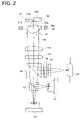
- FIG. 2 is a schematic diagram showing a structure of the optical pick-up apparatus of the present embodiment.
- FIG. 3( a ) is a drawing of a light path, when DVD is used in Examples 1 and 2.
- FIG. 3( b ) is a drawing of a light path, when CD is used.
- FIG. 2 shows the schematic structure of the optical pick-up apparatus of the embodiment of the present invention.
- the optical pick-up apparatus shown in FIG. 2 is structured in such a way that:
- recording and/or reproduction of information can be performed on information recording surfaces 31 a and 32 a of first optical disk 31 and second optical disk 32 , by the light fluxes of wavelengths of 655 nm and 785 nm from the first and the second light sources, respectively.
- the optical pick-up apparatus is provided with the optical system, including:
- coupling lens 16 which refracts both light rays coming from first semiconductor (a first light source) laser 11 which emits light flux at a wavelength of 655 nm for DVD use, and light rays coming from second semiconductor (a second light source) laser 12 which emits light flux at a wavelength of 785 nm for CD use, to make nearly parallel fluxes of infinite-point rays, and
- objective lens 18 which brings the infinite-point rays from coupling lens 16 to a focal point on information recording surfaces 31 a and 32 a of optical disks 31 and 32 , respectively.
- each of light sources 11 and 12 and coupling lens 16 arranged are:
- the light flux is reflected by information recording surfaces 31 a and 32 a of each of optical disks 31 and 32 , then the optical paths of the light flux are changed by beam splitter 14 , and the light flux travels to optical detector 21 .
- Objective lens 18 has flange section 18 a on its outermost side, by which it is possible to attach objective lens 18 on the optical pick-up apparatus.
- Flange section 18 a has a surface projecting perpendicularly to the optical axis of objective lens 18 so that it is possible to be mounted precisely.
- Objective lens 18 is driven toward the focusing direction and the tracking direction by double shaft actuator 22 .
- the ring-shaped diffractive structure for the correction of the spherical aberration is formed to correct the spherical aberration caused by the difference of the thickness between protective substrates 31 a and 32 b of each of optical disks 31 and 32 , at the central area on the optical surface of objective lens 18 , which is used for recording and/or reproduction of information on both first optical disk 31 and second optical disk 32 .
- the ring-shaped diffractive structure is one which compensates for spherical aberration of the focal point on information recording surface 31 a to be in a range where effective recording and/or reproduction of first optical disk 31 can be performed, when the refractive indexes of coupling lens 16 and objective lens 18 and the emission wavelength of first light source 11 are changed due to change of temperature of the optical pick-up apparatus during use.
- the above-mentioned ring-shaped diffractive structure is formed on the peripheral area of objective lens 18 which is used mainly for reproduction or recording of information for first optical disk 31 .
- the central area of objective lens 18 includes the optical axis of the lens, and is a common area for DVD and CD use, whereas the peripheral area is positioned around the central area, and is used exclusively for DVD.
- first optical disk (DVD) 31 In case of information reproduction from first optical disk (DVD) 31 , a light beam is emitted from first semiconductor laser 11 , which passes through beam splitters 13 and 14 , quarter wavelength plate 15 , and coupling lens 16 to become a parallel light beam.
- the parallel light beam passes through diaphragm 17 , and is converged on information recording surface 31 a by objective lens 18 , through protective substrate 31 b of first optical disk 31 .
- the light beam is modulated by information pits on information recording surface 31 a and is reflected, passes back through objective lens 18 , diaphragm 17 , coupling lens 16 , and quarter wavelength plate 15 , next, the light beam is reflected by beam splitter 14 , and is given astigmatism by cylindrical lens 19 , after that, the light beam passes through concave lens 20 , and enters optical detector 21 .
- focal detection and track detection are performed by detecting a change in the amount of light caused by the change of position and the change of shape of specific spot on optical detector 21 , yet further, based on the above-mentioned detection, double shaft actuator 22 moves objective lens 18 in the focusing direction so that the light beam from first semiconductor laser 11 is brought into focus on information recording surface 31 a of first optical disk 31 , and double shaft actuator 22 also moves objective lens 18 in the tracking direction so that the light beam from first semiconductor laser 11 is brought into focus on a predetermined track.
- the information recording on first optical disk 31 is performed in the same way as mentioned above.
- a light beam is emitted from first semiconductor laser 12 , which is reflected by beam splitter 13 , and passes through beam splitter 14 , quarter wavelength plate 15 , and coupling lens 16 , to become a parallel light beam.
- the parallel light beam passes through diaphragm 17 , and is converged on information recording surface 32 a by objective lens 18 , through protective substrate 32 b of second optical disk 32 .
- the light beam is modulated by information pits on information recording surface 32 a and is reflected, passes back through objective lens 18 , diaphragm 17 , coupling lens 16 , and quarter wavelength plate 15 , next, the light beam is reflected by beam splitter 14 , and is given astigmatism by cylindrical lens 19 , after that, passes through concave lens 20 , and enters optical detector 21 .
- information recorded on second optical disk 32 is read-out, and information read-out signals are produced.
- Focal detection and track detection are performed by detecting a change in the amount of light caused by the change of position and the change of shape of the specific spot on optical detector 21 , then, based on the above-mentioned detection, double shaft actuator 22 moves objective lens 18 in the focusing direction so that the light beam from second semiconductor laser 12 is brought into focus on information recording surface 32 a of second optical disk 32 , and double shaft actuator 22 also moves objective lens 18 in the tracking direction so that the light beam from first semiconductor laser 12 is brought into focus on a predetermined track.
- the information recording on second optical disk 32 is performed in the same way as mentioned above.
- the present invention will be described in detail below, showing Examples 1 and 2 of the optical systems in which the objective lens and the coupling lens are paired, however, the present invention is not limited to these examples.
- the first optical information recording medium is a DVD (design base wavelength: 655 nm)
- the second optical information recording medium is a CD (design base wavelength: 785 nm).
- the optical systems shown in Examples 1 and 2 can be applied to the optical pick-up apparatus shown in FIG. 2 .
- each aspheric surface has the aspheric shape shown in Expression 4, in which “Z” is parallel to the optical axis, “h” is perpendicular to the optical axis, “r” is a paraxial radius of curvature, “K” is a cone coefficient, and “A” is an aspheric coefficient.
- the diffractive structure formed on the objective lens is shown by the following Expression 5, using ⁇ B as the optical path difference function, and radian units.
- Example 1 features an optical system in which the light rays, parallel to the optical axis, enter the objective lens from the coupling lens, in both cases of DVD and CD.
- FIG. 3 ( a ) shows the optical path for DVD usage
- FIG. 3( b ) shows the optical path for CD usage.
- Table 1 shows lens data of Example 1.
- Example 2 is the optical system in which the light rays parallel to the optical axis enter the objective lens from the coupling lens, in the case both for DVD and CD.
- the optical path for DVD usage is the same as that shown in FIG. 3( a ), and the optical path for CD usage is the same as that shown in FIG. 3( b ).
- Table 2 shows lens data of Example 2.
- spherical aberration, caused by the thickness difference between the protective substrates, is corrected by the ring-shaped diffractive structure formed in the common area for DVD and CD of the objective lens, and the spherical aberration caused by the temperature change is corrected by the ring-shaped diffractive structure formed in the exclusive DVD area.
- the 3rd spherical-aberration variation amount ⁇ SA 3 [ ⁇ rms]/ ⁇ T[° C.] and the 5th spherical aberration variation amount ⁇ SA 5 [ ⁇ rms]/ ⁇ T[° C.] satisfy the conditions shown by the above-mentioned formulas (7) and (8), respectively. Further, they satisfy the condition shown by the above-mentioned formulas (9) and (10), respectively.
- the 3rd spherical aberration variation amount ⁇ SA 3 [ ⁇ rms]/ ⁇ T[° C.] and the 5th spherical aberration variation amount ⁇ SA 5 [ ⁇ rms]/ ⁇ T[° C.] satisfy the conditions shown by the above-mentioned formulas (1) and (2), respectively. Further, they also satisfy the conditions shown by the above-mentioned formulas (4) and (6), respectively.
- f 1 is the focal length (mm) of the objective lens on the information recording surface for a DVD
- f 2 is the focal length (mm) of the objective lens on the information recording surface for a CD
- NA 1 is the numerical aperture of the image side of the objective lens for the DVD usage
- NA 2 is the numerical aperture of the image side of the objective lens for the CD usage.
- E shows powers of 10 that is, E-02 or E-2 means 10 ⁇ 2 .
- the optical pick-up apparatus which performs at least either recording or reproduction for a plurality of information recording media which are of various types, it is possible to provide for a pick-up apparatus and an objective lens for the pick-up apparatus which can correct for the spherical aberration caused by a temperature change in the optical system, when recording or reproduction is performed by shorter wavelength light beams.
Applications Claiming Priority (2)
| Application Number | Priority Date | Filing Date | Title |
|---|---|---|---|
| JPJP2002-101049 | 2002-04-03 | ||
| JP2002101049A JP2003296961A (ja) | 2002-04-03 | 2002-04-03 | 光ピックアップ装置及び光ピックアップ装置用対物レンズ |
Publications (2)
| Publication Number | Publication Date |
|---|---|
| US20030189886A1 US20030189886A1 (en) | 2003-10-09 |
| US7158467B2 true US7158467B2 (en) | 2007-01-02 |
Family
ID=28672091
Family Applications (1)
| Application Number | Title | Priority Date | Filing Date |
|---|---|---|---|
| US10/400,655 Expired - Fee Related US7158467B2 (en) | 2002-04-03 | 2003-03-28 | Optical pick-up apparatus and objective lens for the optical pick-up apparatus |
Country Status (3)
| Country | Link |
|---|---|
| US (1) | US7158467B2 (ja) |
| JP (1) | JP2003296961A (ja) |
| CN (1) | CN100375170C (ja) |
Cited By (1)
| Publication number | Priority date | Publication date | Assignee | Title |
|---|---|---|---|---|
| US9121702B2 (en) | 2010-11-09 | 2015-09-01 | Panasonic Corporation | Distance measurement apparatus and distance measurement method |
Families Citing this family (5)
| Publication number | Priority date | Publication date | Assignee | Title |
|---|---|---|---|---|
| DE10319268A1 (de) * | 2003-04-25 | 2004-12-02 | Carl Zeiss Sms Gmbh | Diffraktiver Strahlteiler für Abbildungssysteme |
| JP4321217B2 (ja) * | 2003-10-31 | 2009-08-26 | コニカミノルタオプト株式会社 | 光学素子及び光ピックアップ装置 |
| JP2005141800A (ja) * | 2003-11-04 | 2005-06-02 | Konica Minolta Opto Inc | 発散角変換素子及び光ピックアップ装置 |
| JP2005158089A (ja) * | 2003-11-20 | 2005-06-16 | Matsushita Electric Ind Co Ltd | 光ディスク用の対物レンズとそれを用いた光ヘッド装置 |
| WO2013077071A1 (ja) * | 2011-11-21 | 2013-05-30 | コニカミノルタ株式会社 | 光ピックアップ装置用の対物レンズ、光ピックアップ装置及び光情報記録再生装置 |
Citations (3)
| Publication number | Priority date | Publication date | Assignee | Title |
|---|---|---|---|---|
| US6515955B2 (en) * | 2000-04-14 | 2003-02-04 | Pentax Corporation | Objective optical system for optical pick-up |
| US6594222B2 (en) * | 1999-12-28 | 2003-07-15 | Pentax Corporation | Objective lens for optical pick-up |
| US6751021B2 (en) * | 2000-11-14 | 2004-06-15 | Koninklijke Philips Electronics N.V. | Optical scanning device |
Family Cites Families (2)
| Publication number | Priority date | Publication date | Assignee | Title |
|---|---|---|---|---|
| EP0800170B1 (en) * | 1996-04-03 | 2006-03-22 | Konica Corporation | Optical system for recording and/or reproducing an optical information recording medium |
| WO2001026103A1 (fr) * | 1999-10-06 | 2001-04-12 | Sony Corporation | Lentille d'objectif et capteur optique |
-
2002
- 2002-04-03 JP JP2002101049A patent/JP2003296961A/ja active Pending
-
2003
- 2003-03-28 US US10/400,655 patent/US7158467B2/en not_active Expired - Fee Related
- 2003-03-31 CN CNB031084273A patent/CN100375170C/zh not_active Expired - Fee Related
Patent Citations (3)
| Publication number | Priority date | Publication date | Assignee | Title |
|---|---|---|---|---|
| US6594222B2 (en) * | 1999-12-28 | 2003-07-15 | Pentax Corporation | Objective lens for optical pick-up |
| US6515955B2 (en) * | 2000-04-14 | 2003-02-04 | Pentax Corporation | Objective optical system for optical pick-up |
| US6751021B2 (en) * | 2000-11-14 | 2004-06-15 | Koninklijke Philips Electronics N.V. | Optical scanning device |
Cited By (1)
| Publication number | Priority date | Publication date | Assignee | Title |
|---|---|---|---|---|
| US9121702B2 (en) | 2010-11-09 | 2015-09-01 | Panasonic Corporation | Distance measurement apparatus and distance measurement method |
Also Published As
| Publication number | Publication date |
|---|---|
| CN1448928A (zh) | 2003-10-15 |
| JP2003296961A (ja) | 2003-10-17 |
| US20030189886A1 (en) | 2003-10-09 |
| CN100375170C (zh) | 2008-03-12 |
Similar Documents
| Publication | Publication Date | Title |
|---|---|---|
| US7668065B2 (en) | Optical pickup apparatus, recording/reproducing apparatus provided with the optical pickup apparatus, optical element, and information recording/reproducing method | |
| US7327663B2 (en) | Recording reproducing optical system, objective lens, and aberration correcting optical element | |
| US20090080321A1 (en) | Objective lens, optical element, optical pick-up apparatus and optical information recording and/or reproducing apparatus equipped therewith | |
| US7330406B2 (en) | Optical pickup device and optical element used for the same | |
| US8199629B2 (en) | Objective lens for optical pickup device, and optical pickup device | |
| US6590851B1 (en) | Optical pickup for recording/reproducing optical discs of multiple thicknesses | |
| US7120109B1 (en) | Optical pickup with improved collimating lens for use with long and short wavelength laser beams | |
| US8477587B2 (en) | Optical pickup device and objective optical element | |
| US6614600B2 (en) | Objective lens and optical pickup apparatus | |
| US7075880B2 (en) | Optical pick-up device and objective lens used therein | |
| US6856471B2 (en) | Objective optical element, optical pick-up apparatus, and optical information recording reproducing apparatus | |
| US7697392B2 (en) | Optical pickup apparatus and optical information recording and/or reproducing apparatus | |
| US8194522B2 (en) | Aspheric lens and optical pickup including the same | |
| US7050236B2 (en) | Diffractive optical element and optical pickup apparatus | |
| US7529039B2 (en) | Object lens device with high numerical aperture and optical pickup device adopting the same | |
| US7158467B2 (en) | Optical pick-up apparatus and objective lens for the optical pick-up apparatus | |
| US6710939B2 (en) | Objective lens for optical pick-up device and optical pick-up device | |
| US7551371B2 (en) | Optical pickup apparatus and optical disc apparatus | |
| JP4958022B2 (ja) | 光ピックアップ装置 | |
| US20040218503A1 (en) | Objective optical element and optical pickup device | |
| US20060164967A1 (en) | Objective lens and optical pickup device | |
| US6999399B2 (en) | Objective lens, optical pickup device, recorder and reproducer | |
| US7710847B2 (en) | Optical pickup apparatus | |
| US20050141393A1 (en) | Objective lens, optical pickup apparatus and optical information recording and reproducing apparatus | |
| US20060181785A1 (en) | Optical system, optical pickup apparatus, optical disc reproducing and/or recording apparatus and relay lens |
Legal Events
| Date | Code | Title | Description |
|---|---|---|---|
| AS | Assignment |
Owner name: KONICA CORPORATION, JAPAN Free format text: ASSIGNMENT OF ASSIGNORS INTEREST;ASSIGNOR:SAKAMOTO, KATSUYA;REEL/FRAME:013916/0596 Effective date: 20030319 |
|
| FEPP | Fee payment procedure |
Free format text: PAYOR NUMBER ASSIGNED (ORIGINAL EVENT CODE: ASPN); ENTITY STATUS OF PATENT OWNER: LARGE ENTITY |
|
| FPAY | Fee payment |
Year of fee payment: 4 |
|
| FPAY | Fee payment |
Year of fee payment: 8 |
|
| FEPP | Fee payment procedure |
Free format text: MAINTENANCE FEE REMINDER MAILED (ORIGINAL EVENT CODE: REM.) |
|
| LAPS | Lapse for failure to pay maintenance fees |
Free format text: PATENT EXPIRED FOR FAILURE TO PAY MAINTENANCE FEES (ORIGINAL EVENT CODE: EXP.); ENTITY STATUS OF PATENT OWNER: LARGE ENTITY |
|
| STCH | Information on status: patent discontinuation |
Free format text: PATENT EXPIRED DUE TO NONPAYMENT OF MAINTENANCE FEES UNDER 37 CFR 1.362 |
|
| FP | Lapsed due to failure to pay maintenance fee |
Effective date: 20190102 |