US7154841B2 - Optical information recording medium - Google Patents
Optical information recording medium Download PDFInfo
- Publication number
- US7154841B2 US7154841B2 US10/484,993 US48499304A US7154841B2 US 7154841 B2 US7154841 B2 US 7154841B2 US 48499304 A US48499304 A US 48499304A US 7154841 B2 US7154841 B2 US 7154841B2
- Authority
- US
- United States
- Prior art keywords
- layer
- information
- information layer
- initialization
- optical
- Prior art date
- Legal status (The legal status is an assumption and is not a legal conclusion. Google has not performed a legal analysis and makes no representation as to the accuracy of the status listed.)
- Expired - Lifetime, expires
Links
- 230000003287 optical effect Effects 0.000 title claims abstract description 138
- 239000000758 substrate Substances 0.000 claims abstract description 23
- 238000000926 separation method Methods 0.000 claims abstract description 22
- 230000002441 reversible effect Effects 0.000 claims abstract description 8
- 238000002834 transmittance Methods 0.000 claims description 48
- 238000011423 initialization method Methods 0.000 claims description 22
- 230000001678 irradiating effect Effects 0.000 abstract description 3
- 239000010409 thin film Substances 0.000 abstract description 3
- VYPSYNLAJGMNEJ-UHFFFAOYSA-N Silicium dioxide Chemical compound O=[Si]=O VYPSYNLAJGMNEJ-UHFFFAOYSA-N 0.000 description 22
- 238000000034 method Methods 0.000 description 21
- 239000000463 material Substances 0.000 description 13
- 229910052681 coesite Inorganic materials 0.000 description 12
- 229910052906 cristobalite Inorganic materials 0.000 description 12
- 239000000377 silicon dioxide Substances 0.000 description 12
- 229910052682 stishovite Inorganic materials 0.000 description 12
- 229910052905 tridymite Inorganic materials 0.000 description 12
- 238000004519 manufacturing process Methods 0.000 description 11
- 238000010586 diagram Methods 0.000 description 8
- 229910000618 GeSbTe Inorganic materials 0.000 description 6
- 239000011347 resin Substances 0.000 description 6
- 229920005989 resin Polymers 0.000 description 6
- 239000010408 film Substances 0.000 description 5
- 229910052782 aluminium Inorganic materials 0.000 description 4
- 150000004767 nitrides Chemical class 0.000 description 4
- 238000002425 crystallisation Methods 0.000 description 3
- 230000008025 crystallization Effects 0.000 description 3
- 229910052751 metal Inorganic materials 0.000 description 3
- 239000000203 mixture Substances 0.000 description 3
- 239000004417 polycarbonate Substances 0.000 description 3
- 229920000515 polycarbonate Polymers 0.000 description 3
- 229910052710 silicon Inorganic materials 0.000 description 3
- 238000004544 sputter deposition Methods 0.000 description 3
- 229910052714 tellurium Inorganic materials 0.000 description 3
- 235000005811 Viola adunca Nutrition 0.000 description 2
- 240000009038 Viola odorata Species 0.000 description 2
- 235000013487 Viola odorata Nutrition 0.000 description 2
- 235000002254 Viola papilionacea Nutrition 0.000 description 2
- 239000002390 adhesive tape Substances 0.000 description 2
- 150000001786 chalcogen compounds Chemical class 0.000 description 2
- 239000013078 crystal Substances 0.000 description 2
- 238000010030 laminating Methods 0.000 description 2
- 239000002184 metal Substances 0.000 description 2
- 239000012782 phase change material Substances 0.000 description 2
- 229910052711 selenium Inorganic materials 0.000 description 2
- 229910052726 zirconium Inorganic materials 0.000 description 2
- 229910005542 GaSb Inorganic materials 0.000 description 1
- 229910018321 SbTe Inorganic materials 0.000 description 1
- UCKMPCXJQFINFW-UHFFFAOYSA-N Sulphide Chemical compound [S-2] UCKMPCXJQFINFW-UHFFFAOYSA-N 0.000 description 1
- -1 ZnS Chemical compound 0.000 description 1
- 230000008033 biological extinction Effects 0.000 description 1
- 229910052796 boron Inorganic materials 0.000 description 1
- 238000005229 chemical vapour deposition Methods 0.000 description 1
- 238000001816 cooling Methods 0.000 description 1
- 238000001514 detection method Methods 0.000 description 1
- 230000000694 effects Effects 0.000 description 1
- 238000000313 electron-beam-induced deposition Methods 0.000 description 1
- 230000002708 enhancing effect Effects 0.000 description 1
- 150000002222 fluorine compounds Chemical class 0.000 description 1
- 229910052732 germanium Inorganic materials 0.000 description 1
- 239000011521 glass Substances 0.000 description 1
- 229910052737 gold Inorganic materials 0.000 description 1
- 229910052738 indium Inorganic materials 0.000 description 1
- 238000007733 ion plating Methods 0.000 description 1
- 229910052746 lanthanum Inorganic materials 0.000 description 1
- 229910052745 lead Inorganic materials 0.000 description 1
- 229910052749 magnesium Inorganic materials 0.000 description 1
- 238000002844 melting Methods 0.000 description 1
- 230000008018 melting Effects 0.000 description 1
- 229910052750 molybdenum Inorganic materials 0.000 description 1
- 229920003229 poly(methyl methacrylate) Polymers 0.000 description 1
- 239000004926 polymethyl methacrylate Substances 0.000 description 1
- 229910052709 silver Inorganic materials 0.000 description 1
- 229910052715 tantalum Inorganic materials 0.000 description 1
- 229910052719 titanium Inorganic materials 0.000 description 1
- 229910052721 tungsten Inorganic materials 0.000 description 1
Images


Classifications
-
- G—PHYSICS
- G11—INFORMATION STORAGE
- G11B—INFORMATION STORAGE BASED ON RELATIVE MOVEMENT BETWEEN RECORD CARRIER AND TRANSDUCER
- G11B7/00—Recording or reproducing by optical means, e.g. recording using a thermal beam of optical radiation by modifying optical properties or the physical structure, reproducing using an optical beam at lower power by sensing optical properties; Record carriers therefor
- G11B7/24—Record carriers characterised by shape, structure or physical properties, or by the selection of the material
- G11B7/2403—Layers; Shape, structure or physical properties thereof
- G11B7/24035—Recording layers
- G11B7/24038—Multiple laminated recording layers
-
- G—PHYSICS
- G11—INFORMATION STORAGE
- G11B—INFORMATION STORAGE BASED ON RELATIVE MOVEMENT BETWEEN RECORD CARRIER AND TRANSDUCER
- G11B7/00—Recording or reproducing by optical means, e.g. recording using a thermal beam of optical radiation by modifying optical properties or the physical structure, reproducing using an optical beam at lower power by sensing optical properties; Record carriers therefor
- G11B7/004—Recording, reproducing or erasing methods; Read, write or erase circuits therefor
- G11B7/0055—Erasing
-
- G—PHYSICS
- G11—INFORMATION STORAGE
- G11B—INFORMATION STORAGE BASED ON RELATIVE MOVEMENT BETWEEN RECORD CARRIER AND TRANSDUCER
- G11B7/00—Recording or reproducing by optical means, e.g. recording using a thermal beam of optical radiation by modifying optical properties or the physical structure, reproducing using an optical beam at lower power by sensing optical properties; Record carriers therefor
- G11B7/24—Record carriers characterised by shape, structure or physical properties, or by the selection of the material
- G11B7/241—Record carriers characterised by shape, structure or physical properties, or by the selection of the material characterised by the selection of the material
- G11B7/242—Record carriers characterised by shape, structure or physical properties, or by the selection of the material characterised by the selection of the material of recording layers
- G11B7/243—Record carriers characterised by shape, structure or physical properties, or by the selection of the material characterised by the selection of the material of recording layers comprising inorganic materials only, e.g. ablative layers
- G11B7/2433—Metals or elements of Groups 13, 14, 15 or 16 of the Periodic Table, e.g. B, Si, Ge, As, Sb, Bi, Se or Te
-
- G—PHYSICS
- G11—INFORMATION STORAGE
- G11B—INFORMATION STORAGE BASED ON RELATIVE MOVEMENT BETWEEN RECORD CARRIER AND TRANSDUCER
- G11B7/00—Recording or reproducing by optical means, e.g. recording using a thermal beam of optical radiation by modifying optical properties or the physical structure, reproducing using an optical beam at lower power by sensing optical properties; Record carriers therefor
- G11B7/24—Record carriers characterised by shape, structure or physical properties, or by the selection of the material
- G11B7/26—Apparatus or processes specially adapted for the manufacture of record carriers
- G11B7/268—Post-production operations, e.g. initialising phase-change recording layers, checking for defects
-
- G—PHYSICS
- G11—INFORMATION STORAGE
- G11B—INFORMATION STORAGE BASED ON RELATIVE MOVEMENT BETWEEN RECORD CARRIER AND TRANSDUCER
- G11B7/00—Recording or reproducing by optical means, e.g. recording using a thermal beam of optical radiation by modifying optical properties or the physical structure, reproducing using an optical beam at lower power by sensing optical properties; Record carriers therefor
- G11B7/24—Record carriers characterised by shape, structure or physical properties, or by the selection of the material
- G11B7/241—Record carriers characterised by shape, structure or physical properties, or by the selection of the material characterised by the selection of the material
- G11B7/252—Record carriers characterised by shape, structure or physical properties, or by the selection of the material characterised by the selection of the material of layers other than recording layers
- G11B7/257—Record carriers characterised by shape, structure or physical properties, or by the selection of the material characterised by the selection of the material of layers other than recording layers of layers having properties involved in recording or reproduction, e.g. optical interference layers or sensitising layers or dielectric layers, which are protecting the recording layers
Definitions
- the present invention relates to an optical information recording medium of recording and reproducing information at high speed and high density by using optical means such as a laser beam.
- Reproducing or recording high-density information by utilizing a laser beam has been mainly put into practical use as an optical disk.
- the optical disks can be broadly classified into a reproduction-only type, a recordable type and a rewritable type.
- the reproduction-only type is put into practical use as a compact disk and a laser disk
- the recordable type and rewritable type are put into practical use as a document file, a data file and so on.
- the rewritable optical disks are mainly classified into a magnet-optical type and a phase-change type.
- the phase-change optical disk exploits a reversible state change occurring to a recording layer between an amorphous state and a crystalline state (or between crystals and crystals of further different structure) due to irradiation of the laser beam.
- the irradiation of the laser beam changes at least one of a refractive index and an extinction coefficient of a thin film so as to perform recording. And amplitude of transmitted light or reflected light changes in this portion so that transmitted light volume or reflected light volume leading to a detection system consequently changes, which is detected so as to reproduce a signal.
- a state in which a recording layer material is in the crystalline state is an unrecorded state, where the laser beam is irradiated to put the recording layer material in the amorphous state by melting and rapidly cooling it so as to record the signal.
- laser beam power lower than that for recording is irradiated to put the recording layer in the crystalline state.
- a chalcogen compound is often used as the recording layer material.
- the recording layer made of the chalcogen compound is formed as a film in an amorphous state, and so it is necessary to put the entire recording area in an unrecorded state by crystallization in advance. This entire crystallization is called initialization.
- An initialization process is incorporated into a part of a disk manufacturing process, and the recording layer is put in the crystalline state by using the laser beam or a flash light source.
- the laser beam is irradiated while rotating the disk, and is focused on an information layer.
- the optical head position is radially deviated on the disk so that the entire disk surface is initialized.
- Japanese Patent Application No. 2000-400442 describes the manufacturing method of the phase-change optical disk of the one-side two-layer configuration using blue-violet laser light.
- an object of the present invention is to provide an optical information recording medium capable of improving production efficiency in an initialization process of optical disk mass production and an initialization method thereof.
- a first aspect of the present invention is an optical information recording medium having a plurality of information layers formed on a disciform substrate, wherein:
- said information layer has at least a recording layer of generating optically detectable reversible change between an amorphous phase and a crystalline phase by irradiation of an energy beam;
- the recording layers included in said information layers are crystallized in a concentric strip-shape by the laser beam in advance;
- a reflection coefficient at a laser beam wavelength of crystallizing said recording layer in advance in the area of another information layer opposed to a boundary between a crystalline area and an amorphous area of at least one information layer is lower than the reflection coefficient at the laser beam wavelength of crystallizing the recording layer in advance in the other areas of the another information layers.
- a second aspect of the present invention is the optical information recording medium according to the first aspect of the present invention, wherein it has a first information layer, an optical separation layer, a second information layer and a light transmittance layer on said disciform substrate in receding order from said disciform substrate.
- a third aspect of the present invention is the optical information recording medium according to the second aspect of the present invention, wherein a concentric and strip-shaped area in which said first information layer is crystallized and said second information layer is in an amorphous state exists in the same radius of a disk.
- a fourth aspect of the present invention is the optical information recording medium according to the third aspect of the present invention, wherein said concentric and strip-shaped area is at least on the inner radius side or rim side of the disk.
- a fifth aspect of the present invention is the optical information recording medium according to the third aspect of the present invention, wherein, when a reflection coefficient of said first information layer in the amorphous state is Ra1, and the reflection coefficient in the crystalline state thereof is Rc1 at a laser beam wavelength of crystallizing said first and second information layers, it is Rc1 ⁇ Ra1.
- a sixth aspect of the present invention is the optical information recording medium according to the second aspect of the present invention, wherein a concentric and strip-shaped area in which said first information layer is in the amorphous state and said second information layer is crystallized exists in the same radius of a disk.
- a seventh aspect of the present invention is the optical information recording medium according to the sixth aspect of the present invention, wherein said concentric and strip-shaped area exists at least on the inner radius side or rim side of the disk.
- An eighth aspect of the present invention is the optical information recording medium according to the sixth aspect of the present invention, wherein, when a reflection coefficient of said first information layer in the amorphous state is Ra1, and the reflection coefficient thereof in the crystalline state is Rc1 at a laser beam wavelength of crystallizing said first and second information layers, it is Rc1>Ra1.
- a ninth aspect of the present invention is an initialization method of the optical information recording medium having at least a first information layer, an optical separation layer, a second information layer and a light transmittance layer provided on a disciform substrate in receding order from said disciform substrate, wherein said information layer has at least a recording layer of generating the optically detectable reversible change between the amorphous phase and crystalline phase by irradiation of the energy beam, the initialization method crystallizing in advance the optical information recording medium capable of recording and reproducing the signals in each information layer by the laser beam irradiated through said light transmittance layer, and
- the initialization method of the optical information recording medium wherein, at a wavelength of the laser beam of crystallizing said recording layer in advance, the initialization of said second information layer is started from the area of said second information layer opposed to the inside of the area of a low reflection coefficient of said first information layer.
- a tenth aspect of the present invention is the initialization method of the optical information recording medium according to the ninth aspect of the present invention, wherein, if Rc1 ⁇ Ra1 when the reflection coefficient of said first information layer in the amorphous state is Ra1 and the reflection coefficient in the crystalline state is Rc1, the initialization of said second information layer is started from the area of said second information layer opposed to the inside of the area in which said first information layer is crystallized in advance.
- An eleventh aspect of the present invention is the initialization method of the optical information recording medium according to the ninth aspect of the present invention, wherein, if Rc1>Ra1 when the reflection coefficient of said first information layer in the amorphous state is Ra1 and the reflection coefficient in the crystalline state is Rc1, the initialization of said second information layer is started from the area of said second information layer opposed to the inside of the area in which said first information layer is in the amorphous state.
- a twelfth aspect of the present invention is the initialization method of the optical information recording medium having at least the first information layer, optical separation layer, second information layer and light transmittance layer provided on the disciform substrate in receding order from said disciform substrate, wherein said information layer has at least a recording layer of generating the optically detectable reversible change between the amorphous phase and crystalline phase by irradiation of the energy beam, the initialization method crystallizing in advance the optical information recording medium capable of recording and reproducing the signals in each information layer by the laser beam irradiated through said light transmittance layer, and
- the initialization method of the optical information recording medium wherein, in the case where the transmittance of said second information layer in the crystalline state is lower than that in the amorphous state, the initialization is performed in order of the first information layer and second information layer in the same radius of the first and second information layers, and in the case where the transmittance of said second information layer in the crystalline state is higher than that in the amorphous state, the initialization is performed in order of the second information layer and first information layer in the same radius of the first and second information layers.
- a thirteenth aspect of the present invention is the initialization method of the optical information recording medium according to either the tenth or eleventh aspect of the present invention, wherein the medium has an optical head of initializing said information layers, and uses the optical head to initialize the first information layer and second information layer in order.
- a fourteenth aspect of the present invention is the initialization method of the optical information recording medium according to the twelfth aspect of the present invention, wherein the medium has an optical head of initializing said information layers, and uses the optical head to initialize the first information layer and second information layer.
- a fifteenth aspect of the present invention is the initialization method of the optical information recording medium according to one of the ninth to eleventh aspects of the present invention, wherein initialization areas of the first information layer and second information layer are different.
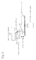
- FIG. 1 is a structure diagram of an optical disk according to an embodiment of the present invention.
- FIG. 2 is a structure diagram of an optical disk initialization apparatus according to the embodiment of the present invention.
- FIG. 3 is a diagram of focus error signals for initialization of an optical disk in the past
- FIGS. 4A–4B are diagrams of focus error signals for initialization of the optical disk according to the embodiment of the present invention.
- FIGS. 5A–5B are is a diagrams showing the configuration of the optical disk (optical information recording medium) according to the embodiment of the present invention.
- FIGS. 6A–6B are diagrams showing the configuration of the optical disk (optical information recording medium) according to the embodiment of the present invention.
- phase-change optical disk of the one-side multilayered configuration using the blue-violet laser light. For instance, it has a first information layer, an optical separation layer, a second information layer and a light transmittance layer provided on a transparent substrate. And a problem arose in the initialization process. There were the cases where the initialization process was successful and the cases where it was unsuccessful depending on the disk configuration.
- the first information layer and second information layer were processed for initialization one by one, but the initialization failed because the laser beam did not focus successfully on the layer to be initialized afterward depending on the disk configuration.
- the initialization was successful with 90-percent probability. The remaining 10 percent was the cases of failure in the focusing for initialization. There were also the cases of unsuccessful initialization depending on the order of the initialization of the first information layer and second information layer.
- the cause of the failure in the initialization can be considered as follows. If the optical head of irradiating the laser beam is moved closer to the light transmittance layer for the sake of the initialization, three signals, that is, a focus error signal 61 from the light transmittance layer, a focus error signal 62 from the second information layer and a focus error signal 63 from the first information layer are detected in that order as shown in FIG. 3 .
- the three focus error signals As for detected sizes of the three focus error signals, however, they are large in the case where a reflection coefficient of each information layer is high, and are small in the case where it is low.
- the reflection coefficient of each information layer changes according to its thin film configuration and combination of phase state (whether amorphous or crystalline), and the probability of the failure in the initialization becomes higher in the case where the focus error signals are small.
- initialization conditions for the initialization of the information layers for instance, linear velocity, laser beam power for the initialization, pickup feed width, laser beam defocus volume to the information layers and so on.
- An initialization apparatus for the mass production having one pickup is used for the initialization of a DVD-RAM and so on currently commercialized.
- the information layers must be initialized one by one in order.
- FIG. 1 The structure of the disc used in this embodiment will be described by using FIG. 1 .
- laser beams of recording and reproducing information and initializing information layers are incident from a light transmittance layer 7 side respectively.
- a substrate 1 is comprised of a resin plate such as polycarbonate or PMMA, a glass plate and so on.
- a substrate surface 2 is covered with a spiral or concentric continuous groove and so on.
- a first information layer 3 is provided on the substrate 1 .
- the first information layer has at least a reflection layer 8 , protection layers 9 and 11 , and a recording layer 10 .
- the optical separation layer 4 is formed on the first information layer 3 .
- the optical separation layer 4 has only to be a material transparent against a wavelength of a laser beam irradiated to record and reproduce a signal in the first information layer 3 , and has a function of optically separating the first information layer from the second information layer.
- the optical separation layer there are a method of forming a layer made of an ultraviolet hardening resin or the like by means of a spin coat, a method of adhering a transparent film with adhesive tape or the ultraviolet hardening resin, and so on.
- a surface of the optical separation layer 5 is covered with the spiral or concentric continuous groove and so on.
- a second information layer 6 is formed on the optical separation layer 4 .
- the second information layer 6 has at least a reflection layer 12 , protection layers 13 and 15 , and a recording layer 14 .
- Alight transmittance layer 7 is formed on the second information layer 6 .
- the layer made of the ultraviolet hardening resin or the like is formed by a spin coat method or the transparent film is adhered on the second optical information layer 6 with the adhesive tape or the ultraviolet hardening resin and so on so as to form it.
- oxides of an element such as Al, Si, Ta, Mo, W and Zr oxides of an element such as Al, Si, Ta, Mo, W and Zr, a sulfide such as ZnS, nitrides of an element such as Al, B, Ge, Si, Ti and Zr, and fluorides of an element such as Pb, Mg and La.
- the material having a composition of ZnS-20 mol % SiO 2 was used in this embodiment.
- phase-change material of which main components are Te, In, Se and so on may be used.
- main components of the phase-change material there are TeGeSb, TeGeSn, TeGeSnAu, SbSe, SbTe, SbSeTe, In—Te, In—Se, In—Se—Tl, InSbInSbSe, GeSbTeAg and so on.
- Material systems of phase-change optical disks which are currently commercialized or researched a great deal are a GeSbTe system and an AgGeSbTe system. These recording layers usually have the film formed in the amorphous state.
- a transmittance in the crystalline state is smaller than a transmittance in the amorphous state as to infrared light wavelength generally used for initialization of the recording layers.
- the material of the GeSbTe system is mainly used in this embodiment.
- the material of which main components are metal elements such as Ag, Au and Al may be used. It is also possible to obtain the same optical characteristic as a non-transmittance layer by laminating two or more kinds of protection layers of different refractive indexes instead of a metal reflection layer.
- the metal reflection layer of which main component is Ag is used in this embodiment.
- the main material of the nitride interface layer is the material including at least one element of Ge, Cr, Si, Al and Te.
- an electron beam deposition method As for the method of forming the layers such as the protection layer, recording layer, reflection layer and nitride interface layer, an electron beam deposition method, a sputtering method, an ion plating method, a CVD method, a laser sputtering method and soon are usually adapted.
- the sputtering method is used in this embodiment.
- the initialization apparatus is an apparatus of initializing an optical disk 51 , and is comprised of a head feed mechanism 52 , a laser light source 53 , a mirror 54 , an objective lens 55 , a focus servo 56 and a spindle motor 57 .
- the laser beam irradiated from the laser light source 53 is focused on the second information layer or first information layer by the objective lens 55 by using an astigmatic method for instance. At this time, focus error signals obtained from the first and second information layers are used.
- various methods such as a knife-edge method can be taken.
- a description will be given as to a procedure of, after forming both the first and second information layers, differentiating the first information layer from the second information layer and focusing the laser beam for initialization on a desired information layer on initializing each information layer.
- the optical head of irradiating the laser beam for the initialization is brought closer to the light transmittance layer, and three focus error signals of achieving focus from the light transmittance layer, second information layer and first information layer are detected in order.
- the focus is achieved on the second focus error signal of the focus error signals detected in the case of bringing the optical head closer to the light transmittance layer.
- the work of achieving focus on the second focus error signal on separating the optical head from the light transmittance layer is performed in the initialization apparatus (in the case of a plurality of information layers instead of two, focusing is performed by the same method).
- the following plurality of patterns are understood as the method of initializing the first and second information layers.
- optical separation layer To perform the initialization after forming the first information layer, optical separation layer, second information layer and light transmittance layer (the light transmittance layer may be formed after the initialization).
- an Ag reflection layer, GeN, ZnS-20 mol % SiO 2 , Ge 22 Sb 25 Te 53 (at %) and ZnS-20 mol % SiO 2 are formed in this order by a magnetron sputter method on a polycarbonate substrate of 120 mm diameter and 1.1 mm thickness of which surface is covered with a concavo-convex guide groove of 0.3 ⁇ m pitch and 20 nm groove depth so as to form the first information layer.
- the optical separation layer is formed by putting the polycarbonate of 120 mm radius and 25 ⁇ m thickness of which surface is covered with the concave-convex guide groove of 0.3 ⁇ m pitch and 20 nm groove depth on the first information layer by using ultraviolet hardening resin such that 30 ⁇ m total thickness if formed.
- the Ag reflection layer, GeN, Ge 22 Sb 25 Te 53 (at %) and ZnS-20 mol % SiO 2 are formed in this order by a magnetron sputter method on the optical separation layer so as to form the second information layer.
- the light transmittance layer of 0.1 mm thickness is formed by the spin coat method.
- the information layers are initialized by using the initialization apparatus having a laser light source of 810 nm wavelength shown in FIG. 2 and experimentally seeking appropriate laser power at linear velocity of 6 m/s and a feed pitch of 20 ⁇ m for each of the first and second information layers.
- the width of the laser beam for the initialization in a radial direction on the disk is 50 ⁇ m.
- the information layers are initialized after forming the first information layer, optical separation layer, second information layer and light transmittance layer.
- the two information layers are initialized in order by using one laser beam for the initialization.
- the disk configuration used for the review is as follows.
- the first information layer has the configuration of the Ag reflection layer of 100 nm, GeN layer of 5 nm, ZnS-20 mol % SiO 2 layer of 25 nm, GeSbTe recording layer of 15 nm and ZnS-20 mol % SiO 2 layer of 60 nm.
- the second information layer there are two different types of recording layer compositions provided.
- a disk 1 after forming the optical separation layer on the first information layer, there are the Ag reflection layer of 10 nm, GeN layer of 5 nm, ZnS-20 mol % SiO 2 layer of 24 nm, GeSbTe recording layer of 6 nm and ZnS —SiO 2 layer of 50 nm.
- the film thickness of each layer is the same as the disk 1, but it is rendered as the disk by only changing the recording layer composition to GaSb.
- the light transmittance layer is formed on the second information layer.
- the transmittances and reflection coefficients of the first and second information layers at the initialization laser beam wavelength are shown in Table 1.
- the above one-side two-layer disk is used to review the yield after the initialization of the two layers is finally completed in the case of initializing the second information layer after initializing the first information layer and vice versa.
- the radial positions of starting the initialization of the first and second information layers are the same, that is, from about 23 mm.
- the disk is removed once from the initialization apparatus after finishing the initialization of the first layer, and the disk is mounted on the initialization apparatus again after setting the initialization condition for the next layer.
- the yield results of the initialization are shown in (Table 2).
- the initialization yield is improved in the case of initializing the second information layer after initializing the first information layer rather than the inverse case.
- initialization mistakes are made less often in the case of initializing the first information layer after initializing the second information layer than the inverse case.
- the reflection coefficient of the first information layer is as high as about 7.2 percent, and so the focus error signals are also large enough to facilitate focusing so that the yield is good.
- the reflection coefficient is about 5.0 percent, and the reflection coefficient of the first information layer at that time is as low as about 2.5 percent so that a possibility of focusing on the first information layer by mistake is low, and so the yield should be good.
- the reflection coefficient of the second information layer is about 5.0 percent, but the reflection coefficient of the first information layer at that time is as high as about 7.2 percent so that there is a possibility of focusing on the first information layer by mistake.
- the reflection coefficient on initializing the first information layer is low as with the reflection coefficient of the second information layer and close thereto, and so it is thinkable that a mistake was made in the initialization of the first information layer.
- the disk 2 it is understood the same reason that the yield improved better in the case of starting the initialization from the second information layer than in the case of starting the initialization from the first information layer.
- the initialization is performed in order of the first information layer and second information layer in the same radius of the first and second information layers.
- the initialization is performed in order of the second information layer and first information layer in the same radius of the first and second information layers.
- the yield is improved.
- the initialization is performed in the above order so that wrong focusing occurs less often when initializing the first information layer so as to consequently improve the yield.
- the transmittance of the second information layer in the amorphous state at a laser beam wavelength of performing the initialization is Ta2
- the reflection coefficient is Ra2
- the transmittance in the crystalline state is Tc2
- the reflection coefficient is Rc2
- the reflection coefficient of the first information layer in the amorphous state without laminating the second information layer is Ra1
- the reflection coefficient in the crystalline state is Rc1
- the disc configuration used for the review is as follows.
- the first information layer has the configuration of the Ag reflection layer of 100 nm, GeN layer of 5 nm, ZnS-20 mol % SiO 2 layer of 25 nm, GeSbTe recording layer of 15 nm and ZnS-20 mol % SiO 2 layer of 60 nm on the substrate.
- the second information layer after forming the optical separation layer on the first information layer, the disk 1 has the Ag reflection layer of 10 nm, GeN layer of 5 nm, ZnS-20 mol % SiO 2 layer of 24 nm, GeSbTe recording layer of 6 nm and ZnS—SiO 2 layer of 50 nm.
- the light transmittance layer is formed on the second information layer.
- the transmittances and reflection coefficients of the first and second information layers at the initialization laser beam wavelength are shown in Table 4.
- the above one-side two-layer disk is used to initialize the first information layer, and then the disk is removed once from the initialization apparatus, and the disk is mounted on the initialization apparatus again after setting the initialization condition for the second information layer so as to initialize the second information layer.
- the yield after completing the initialization was lastly reviewed as to both the layers.
- the radial position of starting the initialization of the first information layer is from 23 mm.
- the second information layer three kinds of the radial positions of starting the initialization of 22 mm, 23 mm and 24 mm were reviewed.
- the initialization is performed from the amorphous area, from the same initialization start position and from the crystalline area of the first information layer respectively. The yield results thereof are shown in (Table 5).
- the yield is reduced in order of starting the initialization from the crystalline area, the same initialization start position and starting it from the amorphous area of the first information layer.
- Table 6 shows the initialization start positions and the reflection coefficients of the laser beams returning from the information layers to the optical head for the initialization.
- FIGS. 4A and 4B show comparisons of the sizes of the focus error signals according to differences in disk radial positions after the initialization of the first information layer.
- FIG. 4A shows the focus error signals at 22 mm radius, which is equivalent to the case of starting the initialization of the second information layer from the amorphous area of the first information layer.
- a focus error signal 71 a from the light transmittance layer, a focus error signal 72 a from the second information layer and a focus error signal 73 a from the first information layer are approximately of the same size.
- FIG. 4B shows the focus error signals at 24 mm radius, which is equivalent to the case of starting the initialization of the second information layer from the crystalline area of the first information layer.
- the focus error signal 73 b from the first information layer is smaller than a focus error signal 71 b from the light transmittance layer and the focus error signal 72 b from the second information layer.
- the focus error signal 73 a from the first information layer in FIG. 4A is smaller than the focus error signal 73 b from the first information layer in FIG. 4B .
- the reflection coefficient on initializing the second information layer is about 5.0 percent on the disk 1, and the reflection coefficient of the first information layer at that time is as low as about 2.5 percent. For that reason, there is no possibility of focusing on the first information layer by mistake, and so the yield is supposedly 100 percent.
- the reflection coefficient on initializing the second information layer is about 5.0 percent on the disk 1.
- the reflection coefficient from the first information layer is about 7.2 percent, and it is understood to focus on the first information layer by mistake, thereby reducing the yield.
- the reflection coefficient should be the same as that in the case of starting the initialization of the second information layer from the crystalline area of the first information layer. In reality, however, the yield results are reduced.
- the cause thereof is supposedly that, as the disk is replaced on initializing the second information layer after initializing the first information layer, the pickup of the initialization apparatus detects reflected light from the amorphous area of the first information layer due to an error in mounting the disk on the initialization apparatus for the replacement so that the focusing fails.
- the mounting error in the disk replacement supposedly occurs from an error in internal or external diameter of the disk or a dimensional error of a disk receptacle portion of the initialization apparatus.
- the initialization of the first information layer is started from the crystalline area of the second information layer if Rc2 ⁇ Ra2, or the initialization of the first information layer is started from the amorphous area of the second information layer if Rc2>Ra2 so as to improve the initialization yield likewise.
- FIGS. 5 and 6 The above will be described further in detail by using FIGS. 5 and 6 .
- FIGS. 5A and 5B show an optical information recording medium 31 in the case of Rc1 ⁇ Ra1, that is, in the case where the reflection coefficient at the laser beam wavelength of crystallizing the recording layer in advance in the crystalline state of the first information layer is smaller than the reflection coefficient at the laser beam wavelength of crystallizing the recording layer in advance in the amorphous state of the first information layer.
- FIG. 5A is a front view of the optical information recording medium 31
- FIG. 5B is a diagram illustrating a first information layer 32 and a second information layer 35 as to an AA′ cross-section of the optical information recording medium 31 in FIG. 5 .
- the optical information recording medium 31 has a disciform shape having around hole at the center thereof.
- the optical information recording medium 31 has both the first information layer 32 and second information layer 35 already initialized. When initializing the second information layer 35 , the initialization is performed from the inner radius side toward the rim side of the optical information recording medium 31 .
- the first information layer 32 is in an amorphous state 34 as to the radius of less than 22 mm, and the first information layer 32 is in a crystalline state 33 as to the radius of 22 mm or more.
- the second information layer 35 is in an amorphous state 37 as to the radius of less than 23 mm, and the second information layer 35 is in a crystalline state 36 as to the radius of about 23 mm or more. Therefore, in the area of the radius between 22 mm and 23 mm of the optical information recording medium 31 , the first information layer 32 is in the crystalline state and the second information layer 35 is in the amorphous state.
- a concentric and strip-shaped area in which the first information layer 32 is in the crystalline state and the second information layer 35 is in the amorphous state exists in the optical information recording medium 31 , such as the area of the radius between about 22 mm and 23 mm thereof. And this concentric and strip-shaped area at least exists on the inner radius side of the disk in the case where the second information layer 35 is initialized from the inner radius side toward the rim side of the optical information recording medium 31 .
- the reflection coefficient at the laser beam wavelength of crystallizing the recording layer in advance in the area of the first information layer 32 opposed to a boundary with the area in the crystalline state 36 and the area in the amorphous state 37 of the second information layer 35 is lower than the reflection coefficient at the laser beam wavelength of crystallizing the recording layer in advance in the other areas of the first information layer 32 .
- the initialization of the second information layer 35 is started from the area of the second information layer 35 opposed to the inside of the area of a low reflection coefficient of the first information layer 32 .
- the initialization of the second information layer 35 is started from the area of the second information layer 35 opposed to the inside of the area in which the first information layer 32 is crystallized.
- Such an optical information recording medium 31 provides a better yield compared to the case where the initialization of the second information layer is started from the area of the second information layer opposed to the inside of the area in which the first information layer is in the amorphous state.
- the initialization is started from the area of the second information layer 35 opposed to the area in which the first information layer 32 is in the crystalline state 33 . Therefore, when starting the initialization of the second information layer 35 , the initialization is started from the area of the second information layer 35 opposed to the area of a low reflection coefficient of the first information layer 32 . And thus, the focus error signals of the first information layer 32 become smaller on starting the initialization of the second information layer 35 so that the first information layer 32 is less often focused on by mistake.
- the second information layer 35 when initializing the second information layer 35 from the inner radius side toward the rim side of the optical information recording medium 31 , the second information layer 35 has its yield improved better in the optical information recording medium 31 on which the first information layer 32 is not crystallized on the inner radius side of the optical information recording medium 31 and on which the concentric and strip-shaped area in the amorphous state exists in the same radius than in any other optical information recording medium.
- the boundary between the crystalline state and the amorphous state on the rim side of the optical information recording medium 31 may coincide or be different between the first information layer 32 and the second information layer 35 .
- the yield is improved by starting the initialization of the second information layer from the inside of the area of a low reflection coefficient of the first information layer.
- the yield is improved by starting the initialization of the second information layer from the area of the second information layer opposed to the inside of the area in which the first information layer is crystallized.
- FIGS. 6A and 6B show an optical information recording medium 41 in the case of Rc1>Ra1, that is, in the case where the reflection coefficient in the crystalline state of the first information layer is larger than the reflection coefficient in the amorphous state thereof.
- FIG. 6A is a front view of the optical information recording medium 41
- FIG. 6B is a diagram illustrating a first information layer 42 and a second information layer 45 as to a BB′ cross-section of the optical information recording medium 41 in FIG. 6 .
- the optical information recording medium 41 has a disciform shape having a round hole at the center thereof as with the optical information recording medium 31 .
- the optical information recording medium 41 has both the first information layer 42 and second information layer 45 already initialized. When initializing the second information layer 45 , the initialization is performed from the rim side toward the inner radius side of the optical information recording medium 41 .
- the first information layer 42 is in an amorphous state 44 in the area having the radius of more than 58 mm, and the first information layer 42 is in the crystalline state 43 in the area having the radius of about 58 mm or less.
- the second information layer 45 is in an amorphous state 47 in the area having the radius of more than 59 mm, and the second information layer 45 is in a crystalline state 46 in the area having the radius of about 59 mm or less.
- the first information layer 42 is in the amorphous state and the second information layer 45 is in the crystalline state.
- the concentric and strip-shaped area in which the first information layer 42 is in the amorphous state and the second information layer 45 is in the crystalline state exists in the optical information recording medium 41 , such as the area of the radius between about 58 mm and 59 mm thereof.
- this concentric and strip-shaped area at least exists on the rim side of the disk in the case where the second information layer 45 is initialized from the rim side toward the inner radius side of the optical information recording medium 41 .
- the reflection coefficient in the area of the first information layer 42 opposed to a boundary between the area in the crystalline state 46 and the area in the amorphous state 47 of the second information layer 45 is lower than the reflection coefficient in the other areas of the first information layer 42 .
- the initialization of the second information layer 45 is started from the area of the second information layer 45 opposed to the inside of the area of a low reflection coefficient of the first information layer 42 .
- the initialization of the second information layer 45 is started from the inside of the area in which the first information layer 42 is in the amorphous state.
- Such an optical information recording medium 41 provides a better yield compared to the case where the initialization of the second information layer is started from the area of the second information layer opposed to the inside of the area in which the first information layer is in the crystalline state.
- the initialization is started from the area of the second information layer 45 opposed to the area in which the first information layer 42 is in the amorphous state 44 . Therefore, when starting the initialization of the second information layer 45 , the initialization is started from the area of the second information layer 45 opposed to the area of a low reflection coefficient of the first information layer 42 . And thus, the focus error signals of the first information layer 42 become smaller on starting the initialization of the second information layer 45 so that the first information layer 42 is less often focused on by mistake.
- the second information layer 45 when initializing the second information layer 45 from the rim side toward the inner radius side of the optical information recording medium 41 , the second information layer 45 has its yield improved better in the optical information recording medium 41 on which the first information layer 42 is in the amorphous state on the rim side of the optical information recording medium 41 and on which the concentric and strip-shaped area in the crystalline state exists in the same radius than in any other optical information recording medium.
- the boundary between the crystalline state and the amorphous state on the inner radius side of the optical information recording medium 41 may coincide or be different between the first information layer 42 and the second information layer 45 .
- the yield is improved by starting the initialization of the second information layer from the area of the second information layer opposed to the inside of the area of a low reflection coefficient of the first information layer.
- the yield is improved by starting the initialization of the second information layer from the area of the second information layer opposed to the inside of the area in which the first information layer is in the amorphous state.
- optical information recording media 31 and 41 shown in FIGS. 5A–5B and 6 A– 6 B respectively have good yields on the initialization.
- the initialization is performed from the inner radius toward the rim according to this embodiment. However, the same effect is also obtained in the case of performing it from the rim toward the inner radius.
- the present invention can provide the optical information recording medium capable of improving production efficiency in an initialization process of optical disk mass production and an initialization method thereof.
Landscapes
- Engineering & Computer Science (AREA)
- Manufacturing & Machinery (AREA)
- Chemical & Material Sciences (AREA)
- Inorganic Chemistry (AREA)
- Optical Recording Or Reproduction (AREA)
- Manufacturing Optical Record Carriers (AREA)
- Optical Record Carriers And Manufacture Thereof (AREA)
Applications Claiming Priority (3)
| Application Number | Priority Date | Filing Date | Title |
|---|---|---|---|
| JP2002106168A JP2003303422A (ja) | 2002-04-09 | 2002-04-09 | 光学的情報記録媒体の製造方法および光学的情報記録媒体 |
| JP2002-106168 | 2002-04-09 | ||
| PCT/JP2003/004423 WO2003085651A1 (en) | 2002-04-09 | 2003-04-08 | Optical information recording medium |
Publications (2)
| Publication Number | Publication Date |
|---|---|
| US20040246881A1 US20040246881A1 (en) | 2004-12-09 |
| US7154841B2 true US7154841B2 (en) | 2006-12-26 |
Family
ID=28786415
Family Applications (1)
| Application Number | Title | Priority Date | Filing Date |
|---|---|---|---|
| US10/484,993 Expired - Lifetime US7154841B2 (en) | 2002-04-09 | 2003-04-08 | Optical information recording medium |
Country Status (8)
| Country | Link |
|---|---|
| US (1) | US7154841B2 (de) |
| EP (1) | EP1494219B1 (de) |
| JP (2) | JP2003303422A (de) |
| KR (1) | KR100912150B1 (de) |
| CN (2) | CN100543846C (de) |
| AT (1) | ATE520125T1 (de) |
| AU (1) | AU2003236315A1 (de) |
| WO (1) | WO2003085651A1 (de) |
Cited By (3)
| Publication number | Priority date | Publication date | Assignee | Title |
|---|---|---|---|---|
| US20050122888A1 (en) * | 2003-12-08 | 2005-06-09 | Yoshitaka Sakaue | Optical information recording medium and method for manufacturing the medium |
| US20070230321A1 (en) * | 2006-03-17 | 2007-10-04 | Noritake Oomachi | Optical disk and optical disk device |
| US20120219123A1 (en) * | 2009-10-30 | 2012-08-30 | Telefonaktiebolaget L M Ericsson (Publ) | Single ended estimation of far-end crosstalk in a digital subscriber line |
Families Citing this family (2)
| Publication number | Priority date | Publication date | Assignee | Title |
|---|---|---|---|---|
| US8040765B2 (en) * | 2008-09-05 | 2011-10-18 | Panasonic Corporation | Initialization method for information recording medium, initialization apparatus for information recording medium, and information recording medium |
| CN102422136B (zh) * | 2009-03-13 | 2016-03-02 | 丹佛斯公司 | 温度传感器单元和用于制造温度传感器单元的方法 |
Citations (8)
| Publication number | Priority date | Publication date | Assignee | Title |
|---|---|---|---|---|
| JPH0991700A (ja) | 1995-09-25 | 1997-04-04 | Sony Corp | 光学記録媒体の初期化方法とこれに用いる初期化装置 |
| JPH10132982A (ja) | 1996-07-12 | 1998-05-22 | Sulzer Thermtec Ag | ポンプの吸入口用の濾過器 |
| JP2000036130A (ja) | 1998-05-15 | 2000-02-02 | Matsushita Electric Ind Co Ltd | 光学情報記録媒体、その記録再生方法、その製造法及び光学情報記録再生装置 |
| WO2001004888A1 (fr) | 1999-07-12 | 2001-01-18 | Matsushita Electric Industrial Co., Ltd. | Support d'enregistrement d'information optique et procede d'initialisation correspondant |
| JP2001250265A (ja) | 2000-03-07 | 2001-09-14 | Sony Corp | 多層光ディスク及びその初期化方法 |
| US20020031632A1 (en) | 2000-09-12 | 2002-03-14 | Kazuya Hisada | Method and apparatus of optical information recording medium, and optical information recording medium |
| US6456584B1 (en) | 1998-05-15 | 2002-09-24 | Matsushita Electric Industrial Co., Ltd. | Optical information recording medium comprising a first layer having a phase that is reversibly changeable and a second information layer having a phase that is reversibly changeable |
| US6660356B1 (en) * | 1999-05-12 | 2003-12-09 | Matsushita Electric Industrial Co., Ltd. | Optical information recording medium, method for producing the same, and method and apparatus for recording/reproducing information thereon |
-
2002
- 2002-04-09 JP JP2002106168A patent/JP2003303422A/ja active Pending
-
2003
- 2003-04-08 CN CNB2007100855989A patent/CN100543846C/zh not_active Expired - Fee Related
- 2003-04-08 EP EP03745953A patent/EP1494219B1/de not_active Expired - Lifetime
- 2003-04-08 KR KR1020047002147A patent/KR100912150B1/ko active IP Right Grant
- 2003-04-08 WO PCT/JP2003/004423 patent/WO2003085651A1/ja active Application Filing
- 2003-04-08 US US10/484,993 patent/US7154841B2/en not_active Expired - Lifetime
- 2003-04-08 AT AT03745953T patent/ATE520125T1/de not_active IP Right Cessation
- 2003-04-08 CN CNB038007959A patent/CN1312674C/zh not_active Withdrawn - After Issue
- 2003-04-08 AU AU2003236315A patent/AU2003236315A1/en not_active Abandoned
- 2003-04-08 JP JP2003582757A patent/JPWO2003085651A1/ja not_active Withdrawn
Patent Citations (13)
| Publication number | Priority date | Publication date | Assignee | Title |
|---|---|---|---|---|
| US5768221A (en) | 1995-09-25 | 1998-06-16 | Sony Corporation | Method of and apparatus for initializing multi-layer optical recording medium |
| JPH0991700A (ja) | 1995-09-25 | 1997-04-04 | Sony Corp | 光学記録媒体の初期化方法とこれに用いる初期化装置 |
| JPH10132982A (ja) | 1996-07-12 | 1998-05-22 | Sulzer Thermtec Ag | ポンプの吸入口用の濾過器 |
| US5759398A (en) | 1996-07-12 | 1998-06-02 | Sulzer Thermtec Ag | Screen for inlet opening of a pump |
| US6456584B1 (en) | 1998-05-15 | 2002-09-24 | Matsushita Electric Industrial Co., Ltd. | Optical information recording medium comprising a first layer having a phase that is reversibly changeable and a second information layer having a phase that is reversibly changeable |
| JP2000036130A (ja) | 1998-05-15 | 2000-02-02 | Matsushita Electric Ind Co Ltd | 光学情報記録媒体、その記録再生方法、その製造法及び光学情報記録再生装置 |
| US6660356B1 (en) * | 1999-05-12 | 2003-12-09 | Matsushita Electric Industrial Co., Ltd. | Optical information recording medium, method for producing the same, and method and apparatus for recording/reproducing information thereon |
| EP1118988A1 (de) | 1999-07-12 | 2001-07-25 | Matsushita Electric Industrial Co., Ltd. | Optisches informationsaufzeichnungsmedium und verfahren zur initialisierung desselben |
| WO2001004888A1 (fr) | 1999-07-12 | 2001-01-18 | Matsushita Electric Industrial Co., Ltd. | Support d'enregistrement d'information optique et procede d'initialisation correspondant |
| US20020018428A1 (en) | 2000-03-07 | 2002-02-14 | Kotaro Kurokawa | Multilayer optical disk and method of initializing the same |
| JP2001250265A (ja) | 2000-03-07 | 2001-09-14 | Sony Corp | 多層光ディスク及びその初期化方法 |
| US20020031632A1 (en) | 2000-09-12 | 2002-03-14 | Kazuya Hisada | Method and apparatus of optical information recording medium, and optical information recording medium |
| JP2002260307A (ja) | 2000-09-12 | 2002-09-13 | Matsushita Electric Ind Co Ltd | 光情報記録媒体の製造方法、製造装置及び光情報記録媒体 |
Non-Patent Citations (1)
| Title |
|---|
| Japanese International Search Report for PCT/JP03/04423, dated Jul. 29, 2003. |
Cited By (5)
| Publication number | Priority date | Publication date | Assignee | Title |
|---|---|---|---|---|
| US20050122888A1 (en) * | 2003-12-08 | 2005-06-09 | Yoshitaka Sakaue | Optical information recording medium and method for manufacturing the medium |
| US7376070B2 (en) * | 2003-12-08 | 2008-05-20 | Matsushita Electric Industrial Co., Ltd. | Optical information recording medium and method for manufacturing the medium |
| US20070230321A1 (en) * | 2006-03-17 | 2007-10-04 | Noritake Oomachi | Optical disk and optical disk device |
| US20120219123A1 (en) * | 2009-10-30 | 2012-08-30 | Telefonaktiebolaget L M Ericsson (Publ) | Single ended estimation of far-end crosstalk in a digital subscriber line |
| US8731185B2 (en) * | 2009-10-30 | 2014-05-20 | Telefonaktiebolaget L M Ericsson (Publ) | Single ended estimation of far-end crosstalk in a digital subscriber line |
Also Published As
| Publication number | Publication date |
|---|---|
| EP1494219A1 (de) | 2005-01-05 |
| WO2003085651A1 (en) | 2003-10-16 |
| AU2003236315A1 (en) | 2003-10-20 |
| EP1494219B1 (de) | 2011-08-10 |
| ATE520125T1 (de) | 2011-08-15 |
| CN101013576A (zh) | 2007-08-08 |
| KR100912150B1 (ko) | 2009-08-14 |
| JP2003303422A (ja) | 2003-10-24 |
| KR20040094387A (ko) | 2004-11-09 |
| CN1312674C (zh) | 2007-04-25 |
| JPWO2003085651A1 (ja) | 2005-08-11 |
| US20040246881A1 (en) | 2004-12-09 |
| CN100543846C (zh) | 2009-09-23 |
| CN1545699A (zh) | 2004-11-10 |
| EP1494219A4 (de) | 2007-10-17 |
Similar Documents
| Publication | Publication Date | Title |
|---|---|---|
| US8009547B2 (en) | Optical recording and reproducing apparatus capable of identifying the type of optical disc based on reflectance, and reproducing method for optical disc | |
| JPH0991700A (ja) | 光学記録媒体の初期化方法とこれに用いる初期化装置 | |
| JP2002117591A (ja) | 情報記録媒体、情報の記録方法、再生方法、記録記録装置及び情報再生装置 | |
| EP1484752B1 (de) | Verfahren zum aufzeichnen von informationen auf einem optischen aufzeichnungsmedium und informationsrekorder | |
| JP2002216391A (ja) | 片面2層ディスクおよび2面4層ディスク | |
| EP1542210B1 (de) | Optisches Speichermedium und Verfahren zu dessen Herstellung | |
| US7154841B2 (en) | Optical information recording medium | |
| EP1516323B1 (de) | Zweischichtiger optischer datenträger und gebrauch desselben | |
| JP4397801B2 (ja) | 光学的情報記録媒体の製造方法 | |
| JP4271116B2 (ja) | 光記録再生装置 | |
| KR100949234B1 (ko) | 광학 기록 매체의 초기화 방법 | |
| JP2002279707A (ja) | 片面2層ディスクの作製方法、該2層ディスク及び記録再生装置 | |
| US7227826B2 (en) | Method of recording information in optical recording medium, information recording apparatus and optical recording medium | |
| US20060062131A1 (en) | Optical information recording medium and production method of the same | |
| JPWO2003025918A1 (ja) | 記録媒体の記録方法及び記録媒体 | |
| JP2003217186A (ja) | 相変化型光ディスクの初期化方法および初期化装置 | |
| JP2007042220A (ja) | 記録方法、記録装置、多層型光記録媒体 |
Legal Events
| Date | Code | Title | Description |
|---|---|---|---|
| AS | Assignment |
Owner name: MATSUSHITA ELECTRIC INDUSTRIAL CO., LTD., JAPAN Free format text: ASSIGNMENT OF ASSIGNORS INTEREST;ASSIGNORS:SAKAUE, YOSHITAKA;NAGATA, KEN'ICHI;REEL/FRAME:015637/0777 Effective date: 20040601 |
|
| STCF | Information on status: patent grant |
Free format text: PATENTED CASE |
|
| FEPP | Fee payment procedure |
Free format text: PAYOR NUMBER ASSIGNED (ORIGINAL EVENT CODE: ASPN); ENTITY STATUS OF PATENT OWNER: LARGE ENTITY |
|
| FPAY | Fee payment |
Year of fee payment: 4 |
|
| FEPP | Fee payment procedure |
Free format text: PAYOR NUMBER ASSIGNED (ORIGINAL EVENT CODE: ASPN); ENTITY STATUS OF PATENT OWNER: LARGE ENTITY Free format text: PAYER NUMBER DE-ASSIGNED (ORIGINAL EVENT CODE: RMPN); ENTITY STATUS OF PATENT OWNER: LARGE ENTITY |
|
| FPAY | Fee payment |
Year of fee payment: 8 |
|
| MAFP | Maintenance fee payment |
Free format text: PAYMENT OF MAINTENANCE FEE, 12TH YEAR, LARGE ENTITY (ORIGINAL EVENT CODE: M1553) Year of fee payment: 12 |