US7120518B2 - Device for generating motion of legged mobile robot - Google Patents
Device for generating motion of legged mobile robot Download PDFInfo
- Publication number
- US7120518B2 US7120518B2 US10/476,153 US47615303A US7120518B2 US 7120518 B2 US7120518 B2 US 7120518B2 US 47615303 A US47615303 A US 47615303A US 7120518 B2 US7120518 B2 US 7120518B2
- Authority
- US
- United States
- Prior art keywords
- model
- instantaneous value
- reaction force
- floor reaction
- movement
- Prior art date
- Legal status (The legal status is an assumption and is not a legal conclusion. Google has not performed a legal analysis and makes no representation as to the accuracy of the status listed.)
- Expired - Lifetime, expires
Links
Images


Classifications
-
- B—PERFORMING OPERATIONS; TRANSPORTING
- B25—HAND TOOLS; PORTABLE POWER-DRIVEN TOOLS; MANIPULATORS
- B25J—MANIPULATORS; CHAMBERS PROVIDED WITH MANIPULATION DEVICES
- B25J5/00—Manipulators mounted on wheels or on carriages
-
- B—PERFORMING OPERATIONS; TRANSPORTING
- B62—LAND VEHICLES FOR TRAVELLING OTHERWISE THAN ON RAILS
- B62D—MOTOR VEHICLES; TRAILERS
- B62D57/00—Vehicles characterised by having other propulsion or other ground- engaging means than wheels or endless track, alone or in addition to wheels or endless track
- B62D57/02—Vehicles characterised by having other propulsion or other ground- engaging means than wheels or endless track, alone or in addition to wheels or endless track with ground-engaging propulsion means, e.g. walking members
- B62D57/032—Vehicles characterised by having other propulsion or other ground- engaging means than wheels or endless track, alone or in addition to wheels or endless track with ground-engaging propulsion means, e.g. walking members with alternately or sequentially lifted supporting base and legs; with alternately or sequentially lifted feet or skid
Definitions
- the present invention relates to a motion generation system of a legged mobile robot, and more particularly to a system for generating or determining a motion of a legged mobile robot and to control the robot to follow up the generated motion.
- the gait of a legged mobile robot has hitherto been generated by trial and error using a strict dynamic model of the legged mobile robot. As a result, it has been difficult to generate a gait on a real-time basis. For that reason, the applicant proposes, in Japanese Laid-Open Patent Application No. Hei 10 (1998)-86081, conducting gait generation freely by converting a set of standard gaits, designed with the use of an off-line computer, into a set of time-series data including parameters and a body trajectory to be stored in a memory of a microcomputer mounted on a robot, and by calculating a weighted average of instantaneous values of individual gaits whose parameters relating to time such as a walking period are the same.
- the “dynamic equilibrium condition” indicates a situation where a ZMP determined from the gravity and inertial force of a desired gait using a strict dynamic model (that expresses behavior of the robot strictly) is equal to a desired ZMP. To be more specifically, it indicates a situation where horizontal component of a moment produced about the desired ZMP by the resultant force of the determined inertial force and gravity of the robot using a strict dynamic model (that expresses behavior of the robot strictly) is zero. (“walking robot and artificial foot” (written by M. Vukobratovic and translated by Kato and Yamashita); published on 1975 by The Nikkan Kogyo Shimbun Kabushiki Kaisha).
- a first object of the present invention is to eliminate the drawback of the above-mentioned technique proposed by the applicant, and to provide a motion generation system of legged mobile robot, in which a generated motion in a gait and the like can satisfy the dynamic equilibrium condition with accuracy.
- a second object of the present invention is to provide a motion control system of legged mobile robot, in which a generated motion in a gait and the like can satisfy the dynamic equilibrium condition with accuracy, and can improve posture stability of the robot by controlling the robot to follow up the generated motion.
- the present invention provides a system for generating an instantaneous value of motion including walking of a legged mobile robot having at least a body and a plurality of legs each connected to the body, when the robot performs the motion, comprising: provisional instantaneous value determining means for determining provisional instantaneous values of a desired movement and a desired floor reaction force or ZMP that constitute the motion; model floor reaction force calculating means for calculating a model's floor reaction force or ZMP based on at least the determined provisional instantaneous value of the desired movement, using a dynamic model that expresses a relationship between the movement of the robot and a floor reaction force or ZMP; difference calculating means for calculating a difference between the calculated model's floor reaction force and the determined provisional instantaneous value of the desired floor reaction force, or a difference between the calculated model's ZMP and the determined provisional instantaneous value of the desired ZMP; and desired instantaneous value determining means for determining desired instantan
- the system is arranged such that, provisional instantaneous values of a desired movement and a desired floor reaction force or ZMP that constitute the motion are determined, a model's floor reaction force or ZMP is then calculated based on the determined provisional instantaneous value of the desired movement, using a dynamic model that expresses a relationship between the movement of the robot and a floor reaction force or ZMP, a difference between the calculated model's floor reaction force and the determined provisional instantaneous value of the desired floor reaction force, or a difference between the calculated model's ZMP and the determined provisional instantaneous value of the desired ZMP is then calculated; and desired instantaneous values of the desired movement and the desired floor reaction force are determined, by correcting at least the provisional instantaneous value of the desired movement based on the calculated difference.
- the system can generate a motion such as a gait that satisfies the dynamic equilibrium condition accurately, and can improve the stability during walking or operation.
- the present invention provides a system for generating a motion including walking of a legged mobile robot having at least a body and a plurality of legs each connected to the body, comprising: desired movement determining means for determining a desired movement that defines the motion; desired floor reaction force calculating means for calculating a desired floor reaction force based on at least the determined desired movement, using a dynamic model that expresses a relationship between the movement of the robot and a floor reaction force; and floor reaction force controlling means for controlling the floor reaction force actually acting on the robot based on at least the calculated floor reaction force.
- the system Since the system is arranged such that, a desired movement that defines the motion is determined, a desired floor reaction force is then calculated based on the determined desired movement, using a dynamic model that expresses a relationship between the movement of the robot and a floor reaction force, and the floor reaction force actually acting on the robot is controlled based on the calculated floor reaction force.
- the system can generate a motion such as a gait that satisfies the dynamic equilibrium condition accurately, and can improve the posture stability, by controlling the robot to follow up the generated motion.
- FIG. 1 is a schematic view showing an overall configuration of a legged mobile robot, more particularly a biped robot, to which a motion generation system of a legged mobile robot according to an embodiment of the present invention is applied;
- FIG. 2 is an explanatory side view showing the structure of the foot of a legged mobile robot illustrated in FIG. 1 ;
- FIG. 3 is a block diagram showing details of a control unit mounted on the robot illustrated in FIG. 1 ;
- FIG. 4 is a block diagram showing the configuration of a motion control system including the motion generation system of a legged mobile robot illustrated in FIG. 1 in a functional manner;
- FIG. 5 is a block diagram functionally showing a gait generator (with full-model correction) illustrated in FIG. 4 ;
- FIG. 6 is an explanatory view showing a multiple-material-point model that is an example of a full-model in the gait generator (with full-model correction);
- FIG. 7 is an explanatory view showing a simplified model (dynamic model) that approximates the legged mobile robot illustrated in FIG. 1 by an inverted pendulum to be used by the gait generator (with full-model correction) illustrated in FIG. 5 ;
- FIG. 8 is a block diagram showing dynamic calculation conducted by a gait generator (proposed in an earlier patent application) with the use of the model illustrated in FIG. 7 ;
- FIG. 9 is a set of time charts showing a trajectory of a point of action P of the resultant force of the inertial force and gravity of the leg's material point, to be used in calculating a pseudo ZMP value ZMPpend indicative of a supporting point of the inverted pendulum in dynamic calculation illustrated in FIG. 8 ;
- FIG. 10 is an explanatory view showing a situation where a trajectory of the body of the robot (illustrated in FIG. 1 ) diverges;
- FIG. 11 is a flow chart showing the operation of the motion generation system of a legged mobile robot illustrated in FIG. 1 ;
- FIG. 12 is an explanatory view explaining a steady turning gait (to be used in the processing in the flow chart of FIG. 11 ) from a robot foot landing position and the like;
- FIG. 13 is an explanatory view explaining a body trajectory of the steady turning gait (to be used in the processing in the flow chart of FIG. 11 ) from the robot foot landing position and the like;
- FIG. 14 is a subroutine flow chart showing the generation of desired instantaneous values referred to in the flow chart of FIG. 11 ;
- FIG. 15 is a table showing variations or modifications of the gait correction conducted in the first to twentieth embodiments of the motion generation system of a legged mobile robot according to the present invention.
- FIG. 16 is a functional block diagram showing the gait correction conducted in the motion generation system of the first embodiment of the motion generation system of a legged mobile robot according to the present invention.
- FIG. 17 is a functional block diagram showing the gait correction conducted in the motion generation system of a legged mobile robot according to a second embodiment of the present invention.
- FIG. 18 a block diagram showing the dynamics calculation using a perturbation model to be used in the gait correction conducted in the motion generation system of a legged mobile robot according to the second embodiment of the present invention
- FIG. 19 is a functional block diagram showing a modification of the gait correction conducted in the motion generation system of a legged mobile robot according to the second embodiment of the present invention.
- FIG. 20 is a functional block diagram similarly showing a modification of the gait correction conducted in the motion generation system of a legged mobile robot according to the second embodiment of the present invention.
- FIG. 21 is a functional block diagram similarly showing a modification of the gait correction conducted in the motion generation system of a legged mobile robot according to the second embodiment of the present invention.
- FIG. 22 is a functional block diagram similarly showing a modification of the gait correction conducted in the motion generation system of a legged mobile robot according to the second embodiment of the present invention.
- FIG. 23 is a functional block diagram showing the gait correction conducted in the motion generation system of a legged mobile robot according to a third embodiment of the present invention.
- FIG. 24 is a functional block diagram showing the gait correction conducted in the motion generation system of a legged mobile robot according to a fourth embodiment of the present invention.
- FIG. 25 is a functional block diagram showing the gait correction conducted in the motion generation system of a legged mobile robot according to a fifth embodiment of the present invention.
- FIG. 26 is a functional block diagram showing the gait correction conducted in the motion generation system of a legged mobile robot according to a sixth embodiment of the present invention.
- FIG. 27 is a functional block diagram showing the gait correction conducted in the motion generation system of a legged mobile robot according to a seventh embodiment of the present invention.
- FIG. 28 is a functional block diagram showing the gait correction conducted in the motion generation system of a legged mobile robot according to an eighth embodiment of the present invention.
- FIG. 29 is a functional block diagram showing the gait correction conducted in the motion generation system of a legged mobile robot according to a ninth embodiment of the present invention.
- FIG. 30 is a functional block diagram showing the gait correction conducted in the motion generation system of a legged mobile robot according to a tenth embodiment of the present invention.
- FIG. 31 is a functional block diagram showing the gait correction conducted in the motion generation system of a legged mobile robot according to an eleventh embodiment of the present invention.
- FIG. 32 is a functional block diagram showing the gait correction conducted in the motion generation system of a legged mobile robot according to a twelfth embodiment of the present invention.
- FIG. 33 is a functional block diagram showing the gait correction conducted in the motion generation system of a legged mobile robot according to a thirteenth embodiment of the present invention.
- FIG. 34 is a functional block diagram showing the gait correction conducted in the motion generation system of a legged mobile robot according to a fourteenth embodiment of the present invention.
- FIG. 35 is a set of time charts explaining re-determination conducted in the gait parameters succeeding to the gait correction of the motion generation system of a legged mobile robot according to the fourteenth embodiment of the present invention.
- FIG. 36 is a functional block diagram showing the gait correction conducted in the motion generation system of a legged mobile robot according to a fifteenth embodiment of the present invention.
- FIG. 37 is a functional block diagram showing the gait correction conducted in the motion generation system of a legged mobile robot according to a sixteenth embodiment of the present invention.
- FIG. 38 is a functional block diagram showing the gait correction conducted in the motion generation system of a legged mobile robot according to a seventeenth embodiment of the present invention.
- FIG. 39 is a functional block diagram showing the gait correction conducted in the motion generation system of a legged mobile robot according to an eighteenth embodiment of the present invention.
- FIG. 40 is a functional block diagram showing the gait correction conducted in the motion generation system of a legged mobile robot according to a nineteenth embodiment of the present invention.
- FIG. 41 is a functional block diagram showing the gait correction conducted in the motion generation system of a legged mobile robot according to a twentieth embodiment of the present invention.
- FIG. 42 is a functional block diagram, similar to FIG. 16 , but showing the gait correction conducted in the motion generation system of a legged mobile robot according to a twenty-first embodiment of the present invention
- FIG. 43 is a functional block diagram, similar to FIG. 17 , but showing the gait correction conducted in the motion generation system of a legged mobile robot according to a twenty-second embodiment of the present invention.
- FIG. 44 is a functional block diagram, similar to FIG. 37 , but showing the gait correction conducted in the motion generation system of a legged mobile robot according to a twenty-third embodiment of the present invention.
- FIG. 45 is a functional block diagram, similar to FIG. 34 , but showing a modification of the twenty-third embodiment.
- FIG. 46 is a functional block diagram, similar to FIG. 5 , but showing an equivalent modification of the first embodiment, etc.
- a biped robot is taken as an example of the legged mobile robot.
- FIG. 1 is an overall schematic view showing a legged mobile robot, more specific, a biped robot to which the motion generation system according to the present invention is applied.
- a biped robot (hereinafter simply referred to “robot”) 1 has a pair of right and left legs (leg links) 2 each composed of six joints.
- the six joints include, arranged successively downward, a pair of hip joints 10 R, 10 L (the right-hand joint is indicated by R and the left-hand joint by L) for rotating legs with respect to hips, a pair of hip joints 12 R, 12 L in the rolling axis (about an X-axis), a pair of hip joints 14 R, 14 L in the pitching axis (about a Y-axis), a pair of knee joints 16 R, 16 L in the pitching axis, a pair of ankle joints 18 R, 18 L in the pitching axis, and a pair of joints 20 R, 20 L in the rolling axis.
- the robot is provided with feet 22 R, 22 L underneath of the joints 18 R(L) and 20 R(L), and a body (trunk) 24 at its top which houses a control unit 26 comprising microcomputers (explained later).
- the joints 10 R(L), 12 R(L), 14 R(L) make up the hip joints
- the joints 18 R(L), 20 R(L) make up the ankle joints.
- the hip joints and knee joints are connected to each other by thigh links 28 R, 28 L
- the knee joints and ankle joints are connected to each other by crus or shank links 30 R, 30 L.
- two arms are connected at upper parts of the body 24 and a head is provided at the top of the body 24 .
- the illustration is omitted.
- each of the legs 2 is given six degrees of freedom.
- “*” represents multiplication in scalar calculation and outer product in vector calculation.
- a position and a velocity of the body 24 indicate a position and its displacement velocity of a predetermined position of the body 24 , specifically a representative point of the body 24 . This will be referred to later.
- a known force sensor (more precisely, known as the six-axis force and torque sensor) 34 is disposed at a position below each ankle joint for generating a signal indicative of three directional components Fx, Fy, Fz of force and three directional components Mx, My, Mz of torque or moment thereby of the force and outputs a signal indicative of foot landing and the floor reaction force (the load acting from the floor).
- the body 24 has an inclination sensor 36 which generates a signal indicative of inclination with respect to a Z-axis (the vertical direction (the direction of gravity)) and its angular velocity.
- the electric motors of the respective joints are coupled with respective rotary encoders which generate signals indicative of angular displacements or rotation amounts of the electric motors.
- a spring mechanism 38 is installed at a position upward from the foot 22 R(L), which constitutes a compliance mechanism 42 together with a sole elastic member 40 attached to the sole of the foot 22 R(L).
- the spring mechanism 38 has a box-like guide member (not shown) connected to the foot 22 R(L), and a piston member (not shown) connected to the side of the ankle joint 18 R(L), 20 R(L) and the force sensor 34 and inserted in the guide member with an elastic member such that it moves in the guide member to a slight extent.
- the foot 22 R(L) illustrated in thick lines shows a condition where no floor reaction force is imparted.
- the spring mechanism 38 and the sole elastic member 40 which constitute the compliance mechanism 42 , deform such that the foot 22 R(L) shifts to the position and posture illustrated in dashed lines.
- This configuration is significant not only for decreasing the foot-landing impact, but also for enhancing the control performance. Since this configuration is disclosed in an application (Japanese Laid-Open Patent Application No. Hei 5 (1993)-305584) proposed by the applicant, no further explanation will be made.
- a joystick 44 is provided at an appropriate location of the biped robot 1 , which enables an operator from the outside to input a demand on gait, such as changing from straight advance to turning.
- FIG. 3 is a block diagram which shows the details of the control unit 26 comprised microcomputers. Outputs from the inclination sensor 36 , etc., are converted into digital signals by an A/D converter 50 and are then transmitted through a bus 52 to a RAM 54 . Output signals from the rotary encoders that are disposed adjacent to the respective electric motors are transmitted through a counter 56 to the kAM 54 .
- the control unit 26 includes a first arithmetic unit 60 and a second arithmetic unit 62 respective of which comprises a CPU.
- the first arithmetic unit 60 conducts the gait generation, calculates joint angle displacement commands, and outputs the same to the RAM 54 .
- the second arithmetic unit 62 reads the commands and the detected values from the RAM 54 , and calculates values (manipulated variables), and outputs the same through a D/A converter 66 and servo-amplifiers to the electric motors which drive the respective joints.
- FIG. 4 is a block diagram showing overall configuration and operation of the motion generation system of legged mobile robot according to the embodiment.
- the system includes a gait generator (with full-model correction) 100 which generates a desired gait freely and on a real-time basis and outputs them as will be explained later.
- the desired gait comprises a desired body posture (trajectory or pattern), a corrected desired body position (trajectory or pattern), a desired foot position and posture (trajectory or pattern), a desired ZMP (desired total floor reaction force central point) (trajectory or pattern), a ZMP-converted value of full-model's corrected moment about desired ZMP, and a desired total floor reaction force (trajectory or pattern).
- foot floor reaction force The floor reaction force acting on each foot 22 R(L) is called a “foot floor reaction force”, whilst the resultant force of the foot floor reaction forces acting on both feet is called a “total floor reaction force”. Since the foot floor reaction force will rarely been referred to in the following, the “floor reaction force” will be used in the meaning of “total floor reaction force” if it is not specifically described.
- the robot 1 should have, as desired values in the control of locomotion, not only a desired movement (or motion) pattern, but also a desired floor reaction force pattern that satisfies the dynamic equilibrium condition against the desired movement pattern.
- the desired floor reaction force is generally described or defined by a point of action and by a force and moment acting thereat. Since the point of action can be set at any point, desired floor reaction force has numerous descriptions. However, if the desired floor reaction force is described by selecting the aforesaid desired floor reaction force central point as the point of action, the moment of force is zero except for its vertical component.
- the desired ZMP trajectory can be used in lieu of the desired floor reaction force central point trajectory.
- the legged mobile robot should have, as desired values to be controlled its locomotion, not only the desired movement (or motion) pattern or trajectory, but also the desired ZMP trajectory (desired floor reaction force pattern)”.
- the desired gait is defined in this specification as follows:
- the desired gait is, in a broad sense, a set of the desired movement (or motion) trajectories and the desired floor reaction force pattern extending over a period of a walking step or steps.
- the desired gait is, in a narrow sense, a set of the desired movement (or motion) trajectories and the ZMP trajectory extending for a period of a single walking step.
- a series of walking is comprised of a series of gaits.
- the desired gait is used to represent that gait defined in the narrow sense, unless it is mentioned to the contrary.
- the desired gait is used to mean a gait extending for a period beginning from the initial state of a two-leg supporting period to the terminal state of a one-leg supporting period succeeding thereto.
- the two-leg supporting period means a period during which the robot 1 supports its weight with two legs 2
- the one-leg supporting period means a period during which the robot supports its weight with one of the two legs (leg link) 2 .
- the leg 2 which does not support the robot weight during the one-leg supporting period is called a “free leg”. Since the definitions are described in detail in the Laid-Open Patent Application (Hei 10(1998)-86081) proposed earlier, no further explanation will be made.
- the object of the present invention is to generate the desired gait defined above accurately and on a real-time basis such that a generated motion in a gaitsand the like can satisfy the dynamic equilibrium condition, thereby enabling stability of motion such as walking.
- the desired gait must satisfy the dynamic equilibrium condition.
- the ZMP trajectory dynamically calculated from the desired movement trajectories of the robot 1 should accord with the desired ZMP trajectory.
- the desired gait must also satisfy conditions of constraint in dynamics that the ZMP must remain within the foot sole floor-contact area during the one-leg supporting period, the joint torque must not exceed a possible maximum power of the joint actuators, etc.
- Condition 5 The desired gait must satisfy boundary conditions.
- Condition 1) results in the boundary condition that the position and velocity of robot's each part such as the body must be continuous in the gait boundary. (If not, infinite force would occur or the ZMP would move far away from the foot sole floor-contact area).
- the initial state of n+1-th gait should correspond to the terminal state of n-th gait, especially in the body position, posture and velocity relative to the foot position. If the initial state of n+1-th gait has been determined, it suffices if the terminal state of n-th gait will be accorded with the n+1-th gait initial state. If not determined, it suffices if the terminal state of n-th gait will be within a range that ensures continuous walking without losing posture stability. However, as will be discussed later, it is quite difficult to determine the terminal state range which ensures continuous walking without losing posture stability.
- the desired gait is generated by a gait generation algorithm including parameter values or time-series table data.
- a gait generation algorithm including parameter values or time-series table data.
- Various kinks of gaits can be generated by changing the parameter values or time-series table data. However, if the parameters or time-series table data are determined without paying careful attention, it is not guaranteed if the generated gait can satisfy all of the conditions mentioned above.
- inverted pendulum model which approximates the behavior of the robot body. If the inverted pendulum's floor point (at which its center of gravity is projected) deviates from the supporting point, the deviation will diverge and the pendulum will turn over. Even when it is turning over, the resultant force of the inertial force and gravity of the inverted pendulum continues to act on the supporting point (in other words, the ZMP is kept equal to the supporting point), and the resultant force remains balanced with the floor reaction force acting through the supporting point.
- the dynamic equilibrium condition can merely describe a relationship between the inertial force and gravity and the floor reaction force of a moving object at every moment.
- the one-leg supporting period requires that the ZMP must be within the supporting leg foot sole floor-contact area, etc. Due to rigid conditions of constraint like this, it is difficult to determine body acceleration and deceleration patterns freely. If the body patterns are determined mainly taking body position into account, the velocity is likely to deviate from a range, and vice versa. Thus, it is difficult to make both the position and velocity equal to desirable values at the same time.
- the gait parameters comprise movement (or motion) parameters and the ZMP parameter (more generally floor reaction force parameter).
- the “floor reaction force parameter” is used in this specification to mean a parameter relating to the floor reaction force pattern with respect to time.
- the ZMP trajectory is expressed by a broken-line pattern as will be explained with reference to FIG. 35 (referred to only in the X-coordinate in the figure) and is described or expressed with respect to the coordinate of X, Y and Z (directions) by the positions of the braking points and passing times of the pattern.
- the movement (or motion) parameters comprise foot (trajectory) parameters and the body (trajectory) parameters.
- the foot trajectory parameters comprise initial free leg (foot lifting) position and posture, terminal free leg (foot landing) position and posture, and durations of the two-leg supporting period and the one-leg supporting period, etc.
- the body trajectory parameters comprise parameters determining the body posture (the direction or inclination of the body 24 in space), parameters determining the body height (value in the Z-direction), parameters determining initial body position (displacement) and velocity, etc.
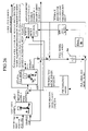
- FIG. 5 is block diagram showing the gait generator (with full-model correction) 100 in details.
- the gait generator (with full-model correction) 100 has a gait parameter determinator 100 a which determines the values (or time-series table) of the parameters in such a manner that they satisfy the aforesaid conditions that the desired gait must satisfy.
- the determined gait parameters are inputted to a desired (and provisional) instantaneous value generator 100 b which generates or calculates the desired foot position and posture, the desired ZMP and desired body posture, more precisely their desired instantaneous values and provisional instantaneous values at time t, based on the inputted values, using techniques proposed by the applicant in Japanese Laid-Open Patent Application Nos. Hei 5-318339 and Hei 5-324115.
- “posture” indicates an inclination or direction (orientation) in space.
- the generated (calculated) desired foot position and posture, the desired ZMP and the desired body posture are inputted to a full-model corrector 100 c .
- the full-model corrector 100 c has a simplified model 100 c 1 (proposed by the applicant in Japanese Patent Application No. 2000-352011) and a full-model 100 c 2 (proposed in the present application and will be explained later), determines the desired body position (more precisely a desired horizontal body position) based on the simplified model and corrects the determined desired body position using the full-model (explained later).
- the full-model 100 c 2 includes an inverse full-model (inverse dynamic model) and a direct full-model (direct dynamic model), as will be explained later.
- the gait generator (with full-model correction) 100 corrects the calculated desired body position using the simplified model in such a way that it can satisfy the dynamic equilibrium condition more accurately than a gait generated merely using such a simplified model.
- the generator 100 outputs a ZMP-converted value of full-model's corrected moment about the desired ZMP, or outputs the ZMP-converted value of full-model's corrected moment about the desired ZMP, while correcting the desired body position.
- the ZMP-converted value of full-model's corrected moment about the desired ZMP may be outputted as not in a ZMP-value, but as in the moment itself.
- desired joint displacement commands can be determined solely from the inverse kinematics solution (as will be explained later) based on the given position and posture of the feet and the body. In other words, a desired robot posture at a current time can be immediately determined.
- the robot's future behavior e.g., a behavior at the time after several walking steps from now, will not diverge, and to correct the gait so as to avoid divergence if a possibility of occurrence of the divergence is predicted.
- FIG. 7 shows the simplified robot dynamic model.
- this dynamic model is a three-material-point model and is decoupled, i.e., the dynamics of the leg (foot) and those of the body do not interfere with each other and the dynamics of the robot as a whole is expressed by their linear combination.
- FIG. 8 is a block diagram showing dynamic calculation (conducted at a dynamic calculator in the gait generator 100 ) using the dynamic model illustrated in FIG. 7 .
- This model comprises three material points made up of an inverted pendulum, a foot material point of the supporting leg and a foot material point of the free leg.
- the supporting leg foot material point is set at a fixed point on a coordinate system set locally at the supporting leg foot.
- the coordinate system is an XYZ rectangular coordinate system in which the origin is defined on a sole of the foot, projected from the center of ankle onto the sole of the foot, the X-Y plane is equal to the sole and the X-axis is defined as the direction from the heel to toe.
- This coordinate system is hereinafter referred to as “supporting leg local coordinate system”.
- a coordinate system on the fixed point on the supporting leg local coordinate system is hereinafter referred to as “supporting leg foot material point's offset”.
- the free leg foot material point is set at a fixed point on a coordinate system that is set at the free leg foot.
- This coordinate system is hereinafter referred to as “free leg local coordinate system”.
- a coordinate system on the fixed point on the free leg local coordinate system is hereinafter referred to as “free leg foot material point's offset”.
- a coordinate system whose origin is defined on a foot point projected from the center of ankle onto the floor when the supporting leg foot is entirely in contact with the floor, and whose coordinate axes are fixed on the floor in such a manner that the X-axis is defined as the front direction of the supporting leg foot, the Y-axis is defined in the left direction and the Z-axis is defined in the vertical direction, is hereinafter referred to as “supporting leg coordinate system” (that is different from the above-mentioned supporting leg local coordinate system). Unless it is mentioned to the contrary, the position, the velocity, the force, etc., are expressed by the supporting leg coordinate system.
- the inverted pendulum comprises a supporting point a that is freely movable in the horizontal direction, a material point b and a link c that connects the supporting point and the material point.
- the link is expansible and has no mass. It is assumed here that the link expands, when tilting, such that the height of the mass viewed from the supporting point is kept constant.
- the material point of the inverted pendulum corresponds to the material point of the body 24 in the sense of physics (the body's material point does not always indicate the center of gravity). Accordingly, the material point of the inverted pendulum is the same as the material point of the body.
- the position (more broadly, the displacement) of the inverted pendulum's material point is simply referred to as “inverted pendulum position”.
- the horizontal position of the body is geometrically determined from the inverted pendulum's horizontal position. Specifically, it is determined such that a horizontal position (the X-Y coordinate system viewed from the supporting leg coordinate system) of the representative point (hereinafter referred to as “body-representing point”) on a coordinate system locally set at the body (the coordinate is hereinafter referred to as “body coordinate system”) becomes equal to the inverted pendulum's horizontal position. More specifically, the body-representing point and the inverted pendulum's material point b are determined such that they are on the same vertical line, as illustrated in FIG. 7 . A horizontal coordinate of the body-representing point on the body coordinate system is referred to as “body material point's offset”.
- the ZMP of the inverted pendulum shall be present at the supporting point a, since the ZMP is defined as a point at which no moment is generated and the supporting point is free and hence no moment is generated there. Accordingly, since the inverted pendulum's supporting point can be regarded as the ZMP of the pendulum itself, it is referred to as “inverted pendulum's ZMP” and is, on and after, described or expressed as “ZMPpend”.
- xb inverted pendulum's position (body's material point position)
- xb is expressed by three-dimensional vector (XYZ coordinate system vector), if not mentioned to the contrary.
- the height of the inverted pendulum indicates the height from the supporting point to the material point and is described as h.
- d(xb)/dt is the first order differential of xb and indicates the velocity of the inverted pendulum
- d 2 (xb)/dt 2 is the second order differential of xb and indicates the acceleration of the inverted pendulum.
- the value g is a constant of the acceleration of gravity.
- G is a vector of the acceleration of gravity and is defined as a vector whose X, Y components are zero (0) and Z component is ⁇ g.
- moment of total inertial force of the leg material point acting about a point of action P is defined as “leg's total inertial force moment about point P”.
- total inertial force the resultant force of the inertial force and gravity is hereinafter referred to “total inertial force”.
- the coordinate (or position) of the point of action P is described as xp.
- Eq. 1 is an equation strictly defining, in terms of dynamics, of the leg's total inertial force moment about P.
- Leg's total inertial force moment about P msup ( xsup ⁇ xp )* G ⁇ msup ( xsup ⁇ xp )* d 2( xsup )/ dt 2+ mswg ( xswg ⁇ xp ) *G ⁇ mswg ( xswg ⁇ xp ) *d 2( xswg )/ dt 2
- the feet ZMP is described as ZMPfeet and is defined by Eq. 2.
- the height of the feet ZMP i.e., the Z component of ZMPfeet
- the feet ZMP is set to the same value as the height of the point P.
- the feet ZMP is a pseudo value to be corresponding to the resultant force (total inertial force) generated by the leg motion.
- Leg's total inertial force moment about P m feet*( ZMP feet ⁇ xp )* G Eq. 2
- the point of action P is set to improve the accuracy of model approximation.
- the point of action P is set in such a manner that it moves, at the same speed during the two-leg supporting period, from the origin of the supporting leg coordinate system of gait immediately before (last time gait) to that of the current time gait.
- the dynamic model proposed in this earlier application is expressed by the offsets describing the relationship between the foot, the body and the material points illustrated in FIG. 7 and the equations (Eqs. 1 to 4). This configuration makes it easy to predict future behavior, as will be explained later.
- a dynamic calculator of the earlier application has a feet ZMP calculator 200 .
- the calculator 200 calculates the feet ZMP (ZMPfeet) based on Eqs. 1 and 2 and on the point of action P illustrated in FIG. 9 .
- the inverted pendulum's ZMP calculates the inverted pendulum's ZMP (ZMPpend) by multiplying the calculated ZMPfeet by mfeet/mtotal (second coefficient), by subtracting the product from the desired ZMP, and by multiplying the difference by mtotal/mb (first coefficient).
- the inverted pendulum's ZMP is determined or calculated by subtracting the product obtained by multiplying ZMPfeet (corresponding to or indicative of the feet ZMP) by the ratio between the leg's mass mfeet and the body material point's mass mb from the product obtained by multiplying the desired ZMP by the ratio of the robot mass mtotal and the body material point's mass mb.
- This processing corresponds to the processing of Eq. 3.
- the behavior of the inverted pendulum is expressed by Eq. 4. From this, the inverted pendulum material point's horizontal position (displacement) xb is determined or calculated.
- the dynamic calculator has a body position determinator 202 which determines the horizontal body position xb. Specifically, the determinator 202 determines the horizontal body position in such a way that the horizontal position of the body-representing point (illustrated in FIG. 7 ) is equal to the horizontal position of the inverted pendulum.
- this model is a model obtained by modeling the robot 1 by an inverted pendulum having at least one material point (that may have the moment of inertia) set at a predetermined position or thereabout of the leg 2 , and at least one material point set at a predetermined point between the supporting point (that is freely movable on the floor) and the body 24
- the dynamic calculator (first model body position calculating means) is arranged to have the feet ZMP calculating means for calculating the feet ZMP (ZMPfeet; indicative of a pseudo ZMP at the feet corresponding to the resultant force of the inertia and gravity generated by a motion of the leg 2 ) without depending on a behavior of the body 24
- the ZMP corresponding value calculating means for calculating a ZMP corresponding value of the inverted pendulum's supporting leg (ZMPpend), based on the calculated feet ZMP (ZMPfeet) and the desired ZMP, the inverted pendulum'
- the ZMP corresponding value of the inverted pendulum's supporting leg is calculated by subtracting the product obtained by multiplying the feet ZMP by the second coefficient (mfeet/mtotal) from the product obtained by multiplying the desired ZMP by the first coefficient (mtotal/mfeet).
- the dynamic model itself does merely calculate the body trajectory from the desired ZMP in such a manner that the dynamic equilibrium condition at each instant is approximately satisfied. It can not prevent the body trajectory from diverging (it can not avoid the position of the body 24 from deviating from a position corresponding to the positions of the feet 22 R(L), as illustrated in FIG. 10 ).
- ⁇ 0 sqrt (g/h) (here, sqrt indicate square root)
- ZMPpend[k] inverted pendulum's ZMP at k-th step (more precisely, it is assured that a signal obtained by zero-order holding the ZMPpend[k] is kept inputted from time k ⁇ t to time (k+1) ⁇ t. More specifically, it is assumed that the same signal is kept inputted to the inverted pendulum during that time of period)
- Eq. 9 can be rewritten as Eq. 11. p[k] ⁇ exp( ⁇ 0 k ⁇ t )* p [0]+(1 ⁇ exp( ⁇ 0 k ⁇ t ))* ZMP max Eq. 11
- Eq. 12 can be obtained. p[k]> exp( ⁇ 0 k ⁇ t )* p[ 0]+(1 ⁇ exp( ⁇ 0 k ⁇ t ))* ZMP min Eq. 12
- p[k] defined by Eq. 5 is referred to as “convergent component” and q[k] similarly defined by Eq. 5 is referred to as “divergent component”.
- the convergent component can be neglected in practice, and what is significant is that to control the divergent component (viewed from the supporting leg) within a range that ensures robot walking.
- the ZMP trajectory parameters and other parameters are appropriately determined such that the divergent component does not exceed the range that ensures robot walking (i.e., the range that prevents posture from deviating markedly).
- the system proposed earlier, it inputs demand (demand value) concerning free leg foot's landing position and posture and landing time for next two walking steps, and determines the desired body position and posture trajectory, the desired foot position and posture trajectory and the desired ZMP trajectory.
- demand demand value
- the gait parameters are partially corrected so as to ensure continuous walking.
- the gaits being generated is referred to as “current time gait”
- a gait succeeding thereto is referred to as “next time gait”
- a gait further succeeding thereto is referred to as “next but one time gait”.
- the technique proposed earlier simplified the dynamic model describing the dynamic behavior of the robot 1 and made possible to predict future robot behavior on a real-time basis and in an analytic manner, thereby enabling to generate a gait including the floor reaction force (desired ZMP) freely and on a real-time basis and to realize a gait of any stride, turning angle and walking period, etc.,
- the motion generation system of a legged mobile robot is arranged such that, even when an excessively-simplified model is used, a generated (corrected) gait can correct robot motion in such a manner that the dynamic equilibrium condition is satisfied more accurately.
- the technique proposed in this embodiment will be applied not only to a case where a motion such as a gait is generated using the simplified model proposed earlier, but also to a case where a motion such as a gait is generated using a gait prepared beforehand as table values.
- the term “full-model” indicates a robot dynamic model that is different from that used in determining a current time gait parameters.
- the full-model is preferably a robot model that is superior in the approximation accuracy to that used in determining the current time gait parameters.
- the full-model should preferably be a robot dynamic model (illustrated, for example, in FIG. 6 ) that is superior in the approximation accuracy to the simplified model (illustrated in FIG. 7 ) used in determining the current time gait parameter (in the technique proposed earlier).
- the full-model may be a model in which the moment of inertia is set about each material point.
- a model used to calculate (or output) the body position based on (with the inputs of) the desired foot position and posture, the desired body posture and the desired ZMP is named “direct dynamic model”
- a model used to calculate (or output) the desired ZMP based on (with the inputs of) the desired foot position and posture, the desired body posture and the body position is named “inverse dynamic model”.
- the full-model provided at the full-model corrector 100 c is a model named “inverse dynamic full-model” (often referred to simply as “inverse full-model”) or a model named “direct dynamic full-model” (often referred to simply as “direct full-model”). Since the direct dynamic model calculation can not be solved analytically, the body position must be determined with searching. The volume of the direct dynamic model calculation is usually greater than that of the inverse dynamic model calculation.
- FIG. 11 is a flow chart (structuralized flow chart) showing the gait generation of the gait generator (with full-model correction) 100 .
- the program begins at S 10 in which various kinds of initialization processing are conducted.
- the program then proceeds, via S 12 , to S 14 in which timer interrupt at every control cycle is waited for.
- the control cycle (period) is ⁇ t.
- the program then proceeds to S 16 in which it is determined whether the gait is at the time of switching. When the result is affirmative, the program proceeds to S 18 , whilst when the result is negative, the program proceeds to S 28 .
- the time t is initialized to zero as a current time.
- the program then proceeds to S 20 in which a next time gait's supporting leg coordinate system, a next but one time gait's supporting leg coordinate system and a current time gait period and a next time gait period are read.
- There values are corresponding to the aforesaid demand. They may be stored in the memory as a walking schedule or may be determined based on an instruction inputted from the joystick 44 or other operator apparatus and the history of walking up to that time.
- the program then proceeds to S 22 in which gait parameters of the current time gait are provisionally determined or calculated.
- the current time gait's initial free leg position and posture are determined to be the current free leg foot position and posture viewed from the current time gait's supporting leg coordinate system (as the initial values).
- the current time gait's initial supporting leg foot position and posture are determined to be the current supporting leg foot position and posture viewed from the current time gait's supporting leg coordinate system (as the initial values).
- the current time gait's terminal free leg foot position and postures are determined in response to the next time gait's supporting leg coordinate system viewed from the current time gait's supporting leg coordinate system.
- the foot position and posture of the free leg foot (obtained when rotated horizontally, without slippage, from terminal position and posture in the current gait, while keeping contact with the floor) will shift to the next gait's supporting leg coordinate system.
- the current time gait's terminal supporting leg foot position and posture are determined to position and posture where the foot is in surface contact with the floor so as not to slip (those are obtained by being rotated from the current supporting position and posture). As a result, if the floor is flat, the current time gait's terminal supporting leg foot position and posture are equal to the current time gait's supporting leg coordinate system. In the gait mentioned here, although the supporting leg foot is made horizontal at the gait terminal, the foot may take other position and posture.
- the ZMP trajectory parameters of the current time gait should be determined such that they are high in the margin of stability and do not change abruptly.
- the phrase “high in the margin of stability” indicates a condition where ZMP is present at the center or thereabout in a minimum convex polygon (the so-called supporting polygon and is described in detail in Japanese Laid-Open Patent Application Hei 10 (1998)-86081).
- the determination of current time gait's ZMP trajectory parameters is provisional and they are subject to correction as will be explained later.
- the program then proceeds to S 24 in which gait parameters of steady turning gait that is to be continuous to the current time gait is determined.
- the “steady turning gait” indicates a periodic gait that does not bring about discontinuity in motion at gait boundary when the gait is repeated.
- the steady turning gait comprises the first turning gait and the second turning gait.
- the reason why the term “turning” is used is that, when the rate of turning is set to zero, since this indicates a straight advance, the term makes it possible to include “straight advance” in “turning” in a broad sense.
- the steady turning gait is generated by the gait generator (with full-model correction) 100 temporarily or tentatively in order to determine the divergent component at the current gait terminal. Therefore, the steady turning gait is not outputted from the gait generator 100 .
- boundary conditions of the leg trajectory in the gait parameters of the first turning gait and the second turning gait are set or determined such that the leg trajectory is made continuous in the order of the current time gait, the first turning gait and the second turning gait.
- the initial free leg foot position and posture of the first turning gait are set to be the terminal supporting leg foot position and posture of the current time gait viewed from the next time gait's coordinate system.
- the initial supporting leg position and posture of the first turning gait are set to be the current time gait's terminal free leg position and posture viewed from the next time gait's supporting leg coordinate system.
- the terminal free leg foot position and posture of the first turning gait are, similarly to the determination of the current time gait's terminal free leg position and posture, set or determined in response to the next but one's time gait's supporting leg coordinate system viewed from the next time gait's supporting leg coordinate system.
- the terminal supporting leg position and posture of the first turning gait are foot position and posture obtained by rotating, while keeping floor contact, the foot (set to the next time gait's supporting leg coordinate system) to be brought in surface contact with the floor so as not to slip. Therefore, if the floor surface is flat, the terminal supporting leg position and posture of the first turning gait become equal to those in the next time gait's supporting leg coordinate system.
- the terminal free leg foot position and posture of the second turning gait are set or determined to be the same as the terminal free leg foot position and posture of the current time gait viewed from the current time gait's supporting leg coordinate system.
- the terminal supporting leg position and posture of the second turning gait are set or determined to be same as those of the supporting leg foot position and posture of the current time gait viewed from the current time gait's supporting leg coordinate system.
- FIG. 12 illustrates relationships among these gait parameters.
- the first turning gait and the second turning gait have the same walking period as that of the next time gait.
- the walking period should not necessarily be determined to be the same value, but should preferably be determined in response to the next time gait walking period.
- Other movement parameters of the current time gait, the first turning gait and the second turning gait should be determined appropriately in response to the determined parameters mentioned above in such a way that they satisfy the conditions of gait (e.g., the velocity of the electric motors (actuators) are within permissible ranges.)
- the ZMP trajectory parameters of the first turning gait and the second turning gait should be set or determined such that they have high margin of stability and do not change abruptly.
- initial position and velocity of the body-representing position are set to values X 0 , V 0
- the initial position and velocity of the body-representing position when the first turning gait generation is again started become equal to the set values X 0 , V 0
- the values X 0 , V 0 are hereinafter referred to as “body-representing point's initial position/velocity of the steady turning gait”.
- FIG. 13 shows this. In the figure, the value X 0 is illustrated as “(x 0 , y 0 )”, and the illustration of V 0 is omitted.
- the program then proceeds to S 28 in which the current time gait is corrected. Specifically, the current time gait parameters are corrected such that the current time gait's terminal divergent component becomes equal to the steady turning gait's initial divergent component. Since the determination is described in detail in Japanese Patent Application No. 2000-352011, no further explanation will be made here, also.
- the program then proceeds to S 30 in which desired (and provisional) instantaneous values of the current time gait are determined from the determined gait parameters.
- FIG. 14 is a flow chart showing the subroutine for this.
- the program begins in S 100 in which the desired ZMP at time (current time) t is determined based on the current time gait parameters, and proceeds to S 102 in which the desired foot position and posture at the time t is determined based on the current time gait parameters. The program then proceeds to S 104 in which the desired body posture at the time t is determined based on the current time gait parameters.
- the program proceeds to S 32 in which a corrected gait is generated (the gait is corrected) using the full-model. Specifically, as explained with reference to FIG. 5 , there are conducted the calculation or determination of the corrected desired body position and the ZMP-converted value of full-model's correct moment about the desired ZMP, etc.
- the gait correction at S 32 of the flow chart of FIG. 11 constitutes the characteristic features of the motion generation of a legged mobile robot of the present invention. Variants or modifications of the features will be discussed in later embodiments. Therefore, the variants or modifications of the gait correction will first be outlined here.
- FIG. 15 is a table showing the variations or modifications of the gait correction. The embodiment corresponding thereto is indicated by its number.
- the gait correction is grouped into methods to use the inverse dynamic full-model (inverse full-model) and those to use the direct dynamic full-model (direct full-model). Each group is then divided into methods not to correct the simplified model's ZMP (the desired ZMP inputted into the simplified model) and that to correct it.
- the group that uses the inverse dynamic full-model, but not to correct the simplified model's ZMP is divided into a group that uses a perturbation dynamic model for correction (hereinafter referred to as “perturbation model”) and that does not use it.
- the group that uses the perturbation model is divided into a group that conducts a feedback (F/B) correction of the full-model and that conducts a feedforward (F/F) correction of the full-model.
- the other group that uses the inverse dynamic full-model and that corrects the simplified model's ZMP is divided into groups in a manner similar to the group that does not correct the simplified model's ZMP.
- FIG. 16 is a functional block diagram showing the gait correction of the motion generation system according to the first embodiment.
- the full-model corrector 100 c corrects the gait by changing the desired body trajectory in the desired gait comprising the desired body trajectory, the desired foot trajectory and the desired ZMP trajectory, or by generating the desired floor reaction force's moment about the desired ZMP (that is zero in the original desired gait).
- the term “full-model's ZMP” indicates a ZMP calculated by using the inverse dynamic full-model (inverse full-model) or by causing the model to output the ZMP.
- the gait is corrected to almost satisfy the dynamic equilibrium condition, since the correction is conducted in a feedforward fashion, it can not correct the gait to strictly satisfy the condition.
- the simplified model's body position (the desired body position) is calculated with the use of the desired foot position and posture, the desired body posture (not shown) and the simplified model.
- the desired body position indicates the “desired body position” before having been corrected as the “corrected desired body position” illustrated in FIG. 4 .
- the feet ZMP (ZMPfeet) at time t is calculated, from the desired foot position and posture at time t and preceding thereto, using Eqs. 1 and 2.
- the inverted pendulum's ZMP (ZMPpend) is calculated using Eq. 3
- the inverted pendulum's horizontal position is then calculated from the inverted pendulum's ZMP using Eq. 4
- the horizontal position of the body is next determined in such a way that it becomes equal to the inverted pendulum material point's horizontal position, whilst the body height is determined using a technique of body height determination proposed by the applicant earlier in Japanese Laid-Open Patent Application No. Hei 10 (1998)-86080.
- Full-model ZMP's error Full-model's ZMP ⁇ Desired ZMP Eq. 15a
- the full-model ZMP's error is determined or outputted as the ZMP-converted value of full-model's corrected moment about the desired ZMP.
- the desired body posture inputted to the inverse full-model is set to an upstanding posture, for the ease of explanation).
- the correction is achieved in such a manner that a deviation from the dynamic equilibrium condition produced by modeling error of the simplified model is canceled by the floor reaction force's moment about the desired ZMP, more specifically, the motion of the leg 2 to push or kick the floor is changed such that the total floor reaction force's moment generated cancels the deviation.
- the ZMP calculated with the use of the inverse full-model is called the full-model's ZMP.
- the body position calculation using the simplified model is determined or outputted as the corrected desired body position, and is inputted into a robot geometric model 103 illustrated in FIG. 4 .
- the desired body posture and the corrected desired body position (trajectory) in the instantaneous values of the desired gait generated by the gait generator (with full-model correction) 100 are forwarded to a later block 102 and are immediately inputted in the aforesaid robot geometric model (inverse kinematics solution) 103 therein.
- the other parameters including the desired foot position and posture (trajectory), the desired ZMP (trajectory), the ZMP-converted value of full-model's corrected moment about the desired ZMP and the desired total floor reaction force (trajectory) are directly forwarded to a composite compliance motion determinator 104 .
- These parameters are also forwarded to a desired floor reaction force distributor 106 where the floor reaction force is distributed to each foot 22 R, L and the desired foot floor reaction force central point and the desired foot floor reaction force are determined.
- the determined parameters are forwarded to the composite compliance motion determinator 104 .
- the composite compliance motion determinator 104 forwards a corrected desired foot position and posture (with deformation compensation) to the robot geometric model 103 .
- the robot geometric model 103 calculates, when inputted with the desired body position and posture (trajectory) and the corrected desired foot position and posture (with deformation compensation) (trajectory), joint displacement commands (command values), for the twelve joints including 10 R, L, to satisfy them and sends the same to a joint displacement controller 108 .
- the joint displacement controller 108 controls the displacement of the twelve joints such that they follow up the calculated joint displacement commands (command values).
- the actual foot floor reaction force resulting in the robot 1 is detected from the output of the six-axis force sensor 34 and the detected values are forwarded to the aforesaid composite compliance motion determinator 104 .
- the actual inclination angular error resulting in the robot 1 is detected from the output of the inclination sensor 36 and the detected value is sent to a posture stabilization controller 112 where a compensating total floor reaction force's moment about the desired ZMP (desired total floor reaction force central point) Mdmd for restoring posture inclination is calculated.
- the aforesaid ZMP-converted value of full-model's corrected moment about the desired ZMP is converted into a moment at a moment converter 114 and is added to the compensating total floor reaction force's moment Mdmd.
- the resultant sum of the moments is forwarded to the composite compliance motion determinator 104 .
- the determinator 104 generates moment corresponding thereto about the desired ZMP by correcting the desired foot position and posture based on the inputted values.
- the system according to the first embodiment can correct the gait generated with the use of the simplified model proposed earlier such that the dynamic equilibrium condition is satisfied accurately. Further, the system can generate a motion of the gait that satisfies the dynamic equilibrium condition accurately and can control the robot 1 to follow up the generated motion, thereby enabling to improve the posture stabilization.
- the gait correction in this embodiment has an advantage that the volume of calculation is decreased since only the floor reaction force is manipulated, the margin of stability of the motion resulting in from the corrected gait is somewhat degraded when compared to the embodiments explained later.
- FIG. 17 is a functional block diagram showing the operation of the motion generation system of a legged mobile robot according to a second embodiment of the present invention. More specifically, it shows the gait correction explained with reference to S 32 of the flow chart of FIG. 11 .
- the gait correction in the second embodiment is a method to use the inverse dynamic full-model (inverse full-model), a method not to correct the ZMP of the simplified model's gait, and a method to use the perturbation model. Further, it is a method of the full-model feedback correction and is the basic of full-model feedback corrections described in the embodiments up to a seventh embodiment.
- a feedback loop is added to the arrangement or structure of the first embodiment.
- the feedback loop inputs a value obtained by integrating (1/S; S: Laplace operator) the full-model ZMP's error and by multiplying it by an integral gain ( ⁇ K that is a value corresponding to a feedback gain) to the perturbation model. And, it inputs a perturbation model's body position outputted from the perturbation model to the inverse-full model as an additional inputted.
- the system calculates the full-model's ZMP, using the inverse full-model, based on the desired foot position and posture, the desired body posture and the corrected desired body position (explained below), calculates an error from the desired ZMP (full-model ZMP's error), and determines (outputs) the error as the ZMP-converted value of full-model's corrected moment about the desired ZMP.
- the body position (calculated with the use of the simplified model) is added with the perturbation model's body position (calculated with the use of the perturbation model), and the sum is determined or outputted as the corrected desired body position.
- the perturbation model is a model that expresses a relationship between the desired ZMP's perturbation and the desired body horizontal position's perturbation under a constraint condition that the foot position and posture are not perturbed. More specifically, it is a model similar to the simplified model illustrated in FIG. 7 , but is modified to express the relationship between the desired ZMP's perturbation and the desired body horizontal position's perturbation without changing behavior of (without perturbing) the feet material points.
- the illustrated arrangement or structure when defining a transfer function of the inverse full-model as 1/G(s) and that of the perturbation model as Gm(s), and approximating that of the simplified model as (G(s)+modeling error), the illustrated arrangement or structure can be approximated by an arrangement shown in FIG. 19 and can be further modified as those as shown in FIGS. 20 and 21 .
- the ZMP-converted value of full-model's corrected moment about the desired ZMP is almost equal to a value obtained by filtering its modeling error by a low-cut filter (high-pass filter) whose cutoff frequency is K/2 ⁇ [Hz] (or whose cutoff angular frequency is K [rad/sec]).
- the system according to the second embodiment can have the same effects as those of the first embodiment and can generate a gait of high margin of stability.
- the system still has the advantage that the volume of calculation is small, since the perturbation model's body position tends to oscillate, the system is not always practical.
- FIG. 23 is a functional block diagram showing the operation of the motion generation system of a legged mobile robot according to a third embodiment of the present invention. More specifically, it shows the gait correction explained with reference to S 32 of the flow chart of FIG. 11 .
- the gait correction in the third embodiment is a method to use the inverse dynamic full-model (inverse full-model), a method not to correct the ZMP of the simplified model's gait, and a method to use the perturbation model. Further, it is a method of the full-model feedback correction and is a general method common to the embodiments up to the seventh embodiment.
- a perturbation model control law 23 e is added to the arrangement or structure of the second embodiment in such a manner that a feedback control amount for controlling the perturbation model (that is an output of the control law) 23 b is inputted to the inverse-full model as an additional input.
- the system calculates the full-model ZMP's error, and outputs the error as the ZMP-converted value of full-model's corrected moment about the desired ZMP.
- it inputs various quantities of states (e.g., perturbation model's inverted pendulum's position and velocity, full-model's center of gravity's position and velocity) and/or the desired gait (the desired gait parameters), and calculates the feedback control amount for controlling the perturbation model using the perturbation model control law.
- the third embodiment In contrast to the second embodiment in which the ZMP-converted value of full-model's corrected moment about the desired ZMP is close to the ideal value (i.e., zero), in the third embodiment, disadvantageously, this value is almost equal to the feedback amount for controlling the perturbation model. For this reason, the feedback control law should be designed in such a way that the feedback amount for controlling the perturbation model becomes small as far as possible (ideally to zero).
- the system according to the third embodiment can have the same effects as those of the second embodiment and can prevent the perturbation model from oscillating.
- FIG. 24 is a functional block diagram showing the operation of the motion generation system of a legged mobile robot according to a fourth embodiment of the present invention. More specifically, it shows the gait correction explained with reference to S 32 of the flow chart of FIG. 11 .
- the gait corrections in the fourth embodiment to a seventh embodiment are concrete examples of the third embodiment. Specifically, the characteristic feature in the corrections is that there is added a control to stabilize the perturbation model at an upstanding position or thereabout.
- Kp and Kv are control gains.
- the embodiment is arranged such that, the feedback amount for controlling the perturbation model is calculated based on the perturbation model's horizontal body position and velocity (that are calculated by using the perturbation model).
- the rest of the arrangement or structure is the same as that of the third embodiment.
- the system according to the fourth embodiment can have the same effects as those of the third embodiment and can prevent the perturbation model from oscillating.
- the fourth embodiment has a disadvantage that an average value of the feedback amount for controlling the perturbation model does not become zero, although the control law is made simple.
- FIG. 25 is a functional block diagram showing the operation of the motion generation system of a legged mobile robot according to a fifth embodiment of the present invention. More specifically, it shows the gait correction explained with reference to S 32 of the flow chart of FIG. 11 .
- the gait correction in the fifth embodiment is also a concrete example of the third embodiment.
- the characteristic feature in, the corrections is that there is included the control of the center of gravity.
- center of gravity difference Full-model's center of gravity position ⁇ Simplified model's center of gravity position Eq. 22
- the embodiment is arranged such that, the feedback amount for controlling the perturbation model is calculated based on the difference of the center of gravity (obtained by subtracting the simplified model's center of gravity position from the full-model's center of gravity position) and the perturbation model's horizontal body velocity (calculated using the perturbation model).
- the perturbation model control law an average value (in time) between the differences of the full-model's center of gravity position and the simplified model's center of gravity position, can be controlled to almost zero.
- the average value (in time) of the feedback amount for controlling the perturbation model becomes almost zero.
- an average value (in time) of the ZMP-converted value of the full-model's corrected moment about the desired ZMP becomes almost zero.
- the system according to the fifth embodiment can have similar effects as those of the fourth embodiment and can make the average value (in time) of the ZMP-converted value of full-model's corrected moment about the desired ZMP almost zero.
- FIG. 26 is a functional block diagram showing the operation of the motion generation system of a legged mobile robot according to a sixth embodiment of the present invention. More specifically, it shows the gait correction explained with reference to S 32 of the flow chart of FIG. 11 .
- the gait correction in the sixth embodiment is also a concrete example of the third embodiment.
- the characteristic feature in the corrections is that the perturbation model's horizontal body position is controlled to follow up an average value (in time) of a product obtained by multiplying the output of the gain K's integrator ( 26 a in FIG. 26 ) by mtotal/mb.
- the low-pass filter output indicates a low-pass filtered value of ⁇ K*mtotal/mb*integrated value of the full-model ZMP's error.
- the value mtotal/mb is the constant of the perturbation model illustrated in FIG. 18 .
- an average value (in time) of the perturbation model's horizontal body position becomes almost equal to an average value of the low-pass filter output. Further, from the nature of the dynamics of the perturbation model, the average value (in time) of the perturbation model's horizontal body position becomes almost equal to a product obtained by multiplying the average value (in time) of the perturbation model's ZMP by the value mtotal/mb (indicative of the inverted pendulum's supporting point position), unless the perturbation model oscillates.
- the average value (in time) of the low-pass filter output is almost equal to a difference obtained by subtracting the product obtained by multiplying the average value (in time) of the perturbation model ZMP by mtotal/mb from a product obtained by multiplying the average value (in time) of the feedback amount for controlling the perturbation model by mtotal/mb. Accordingly, the average value (in time) of the feedback amount for controlling the perturbation model is almost zero.
- the average value (in time) of the ZMP-converted value of full-model's corrected moment about the desired ZMP becomes almost zero.
- the correction according to the sixth embodiment can generate a gait of high margin of stability.
- the rest of arrangement is same as that of the third embodiment.
- FIG. 27 is a functional block diagram showing the operation of the motion generation system of a legged mobile robot according to a seventh embodiment of the present invention. More specifically, it shows the gait correction explained with reference to S 32 of the flow chart of FIG. 11 .
- the gait correction in the seventh embodiment is also a concrete example of the third embodiment, and is an intermediate or compromise method obtained by mixing the methods of the fourth to sixth embodiments.
- the low-pass filter output indicates the low-pass filtered value of ⁇ K*mtotal/mb*integrated value of the full-model ZMP's error.
- the rest of arrangement is same as that of the third embodiment.
- the system according to the seventh embodiment can have intermediate or compromise effects as those of the fourth to sixth embodiment.
- FIG. 28 is a functional block diagram showing the operation of the motion generation system of a legged mobile robot according to an eighth embodiment of the present invention. More specifically, it shows the gait correction explained with reference to S 32 of the flow chart of FIG. 11 .
- the gait correction in the eighth embodiment is a method to use the inverse dynamic full-model (inverse full-model), a method not to correct the ZMP of the simplified model's gait, and a method to use the perturbation model. Further, it is the basic of similar full-model feedforward corrections in the embodiments up to a thirteenth embodiment.
- the full-model ZMP's error is determined by subtracting the desired ZMP (inputted to the simplified model) from the full-model's ZMP, the perturbation model's horizontal body position is then calculated by inputting a product (obtained by multiplying the determined error by ⁇ 1) to the perturbation model, and the corrected desired body position is then determined by adding the simplified model's body position (the desired body position before correction) to the calculated perturbation model's horizontal body position.
- the ZMP-converted value of full-model's corrected moment about the desired ZMP is set to zero. This is ideal, as mentioned in the feedback type correction. Since, however, the perturbation model is likely to oscillate, this basic correction of the eighth embodiment is not practical.
- the body height at joint angle calculation at a preceding (last) control cycle may be used.
- the body height may be calculated from the first. If the perturbation model's body position is not so large, either will make little difference.
- the system according to the eighth embodiment can have the same effects as those of the second embodiment.
- FIG. 29 is a functional block diagram showing the operation of the motion generation system of a legged mobile robot according to a ninth embodiment of the present invention. More specifically, it shows the gait correction explained with reference to S 32 of the flow chart of FIG. 11 .
- the gait correction in the ninth embodiment is a method to use the inverse dynamic full-model (inverse full-model), a method not to correct the ZMP of the simplified model's gait, and a method to use the perturbation model. Further, it is a general method common to feedforward correction methods in the embodiments up to the thirteenth embodiment.
- the perturbation model control law is provided and based thereon, the feedback control amount for controlling the perturbation model is calculated to be additionally inputted to the perturbation model.
- the feedback amount for controlling the perturbation model is determined or outputted as the ZMP-converted value of full-model's corrected moment about the desired ZMP. The rest of the arrangement is the same as the eighth embodiment.
- the approximation accuracy of the gait corrected by the full-model will be somewhat degraded, since the correction amount deviates from an appropriate amount.
- the approximation accuracy of the gait corrected by the full-model is less likely to drop. Nevertheless, since correction error at a certain instant will be remedied (corrected) after expiration of at least one control cycle in the feedforward type, the correction response in the feedforward type is superior to that of the feedback type.
- the system according to the ninth embodiment can have the same effects as those of the third embodiment, except for that derived from the difference in the feedback type and the feedforward type.
- FIG. 30 is a functional block diagram showing the operation of the motion generation system of a legged mobile robot according to a tenth embodiment of the present invention. More specifically, it shows the gait correction explained with reference to S 32 of the flow chart of FIG. 11 .
- the gait correction in the tenth embodiment is a concrete example of the ninth embodiment. Specifically, the characteristic feature in the corrections is that there is included a control to stabilize the perturbation model at an upstanding position or thereabout.
- the system according to the tenth embodiment can have same effects as those of the ninth embodiment and the fourth embodiment.
- FIG. 31 is a functional block diagram showing the operation of the motion generation system of a legged mobile robot according to an eleventh embodiment of the present invention. More specifically, it shows the gait correction explained with reference to S 32 of the flow chart of FIG. 11 .
- the gait correction in the eleventh embodiment is also a concrete example of the ninth embodiment and like the fifth embodiment, the control of the center of gravity is similarly conducted. Specifically, it controls the perturbation model, by setting a desired settling position at a position where the center of gravity's deviation is canceled.
- the system according to the eleventh embodiment can have same effects as those of the ninth embodiment and the fifth embodiment.
- FIG. 32 is a functional block diagram showing the operation of the motion generation system of a legged mobile robot according to a twelfth embodiment of the present invention. More specifically, it shows the gait correction explained with reference to S 32 of the flow chart of FIG. 11 .
- the gait correction in the twelfth embodiment is also a concrete example of the ninth embodiment.
- the perturbation model's horizontal body position is controlled to follow up a product obtained by multiplying the average value (in time) of the ZMP error by ( ⁇ 1) and by the value mtotal/mb. In other words, it controls the perturbation model, by setting the desired settling position at a position where an averaged deviation (in time) of the ZMP error is canceled.
- the low-pass filter output indicates a low-pass filtered value of ⁇ mtotal/mb*full-model ZMP's error.
- the twelfth embodiment is a feedforward modification of the sixth embodiment.
- the system according to the twelfth embodiment can have similar effects as those of the ninth embodiment and the sixth embodiment.
- FIG. 33 is a functional block diagram showing the operation of the motion generation system of a legged mobile robot according to a thirteenth embodiment of the present invention. More specifically, it shows the gait correction explained with reference to S 32 of the flow chart of FIG. 11 .
- the gait correction in the thirteenth embodiment is also a concrete example of the ninth embodiment, and like the seventh embodiment, it is an intermediate or compromise method obtained by mixing the methods of the tenth to twelfth embodiments.
- the low-pass filter output indicates the low-pass filtered value of ⁇ mtotal/mb*full-model ZMP's error.
- the system according to the thirteenth embodiment can have intermediate or compromise effects as those of the tenth to twelfth embodiment.
- FIG. 34 is a functional block diagram showing the operation of the motion generation system of a legged mobile robot according to a fourteenth embodiment of the present invention.
- the gait correction in the fourteenth embodiment is a method to use the inverse dynamic full-model (inverse full-model), a method to correct the ZMP of the simplified model's gait, and a method not to use the perturbation model.
- a feedback loop is added to the arrangement or structure of the first embodiment.
- the feedback loop additionally inputs a value obtained by integrating the full-model ZMP's error and by multiplying it by the integral gain ( ⁇ K) to the simplified model. Further, it determines or outputs the simplified model's body position as the corrected desired body position, and it also determines or outputs the full-model's ZMP error as the ZMP-converted value of full-model's corrected moment about the desired ZMP.
- the simplified model's body position deviates from a desired trajectory. Accordingly, it is preferable to newly determine the gait parameters.
- the gait parameter may be re-determined at every control cycle, or at a time corresponding to each breaking point of the ZMP trajectory, or at every walking step. Since the amount of correction of the gait parameters is decreased as the correction is made earlier, the gait parameters should preferably be corrected repeatedly.
- the gait parameters are re-determined in response to the quantity of state of the simplified model and some similar factors at S 28 in the flow chart of FIG. 11 . Since, however, the gait parameter re-determination is described in detail in Japanese Patent Application No. 2000-352011 proposed earlier, no further explanation will be made here.
- the system according to the fourteenth embodiment can have same effects as those of the second embodiment and can prevent the gait from oscillating by correcting the gait parameters.
- FIG. 36 is a functional block diagram showing the operation of the motion generation system of a legged mobile robot according to a fifteenth embodiment of the present invention. More specifically, it shows the gait correction explained with reference to S 32 of the flow chart of FIG. 11 .
- the gait correction in the fifteenth embodiment is a method to use the inverse dynamic full-model (inverse full-model), a method to correct the ZMP of the simplified model's gait, and a method to use the perturbation model. Further, it is a general method of the full-model feedback correction.
- the fifteenth embodiment based on the arrangement or structure of the third embodiment, the product obtained by multiplying the integrated full-model ZMP's error by the integral gain ( ⁇ k) is fed back, through a distributor 36 e, not only to the perturbation model, but also to the simplified model.
- the fifteenth embodiment is an intermediate or a compromise correction method constituted as a mixture of the methods in the third embodiment and the fourteenth embodiment. Since the simplified model's behavior deviates from a desired behavior in this embodiment also, like the fourteenth embodiment, it is necessary to correct the gait parameters. It is alternatively possible to mix the methods in the fourteenth embodiment and in any of the second embodiment and the fourth to seventh embodiments.
- the distributor may distribute the output at the region of frequency.
- it may distribute the output using a non-linear element such as a limiter. Since the system is a feedback system, a sum of the outputs from the distributor need not be equal to its input.
- the system according to the fifteenth embodiment can have same effects as those of the third and fourteenth embodiments or can have intermediate or compromise effects thereof.
- FIG. 37 is a functional block diagram showing the operation of the motion generation system of a legged mobile robot according to a sixteenth embodiment of the present invention. More specifically, it shows the gait correction explained with reference to S 32 of the flow chart of FIG. 11 .
- the gait correction in the sixteenth embodiment is a method to use the direct dynamic full-model (direct full-model), instead of the inverse dynamic full-model (inverse full-model), a method not to correct the ZMP of the simplified model's gait. And, it is a method to control the full-model to follow up the simplified model's gait, specifically, a method to correct the full-model's ZMP such that the body behavior of the full-model follows up that of the simplified model that satisfies the desired ZMP.
- the full-model's body position is calculated using the direct full-model, and the simplified model's body position (i.e., the desired body position before correction) is then subtracted therefrom to determine a difference which is then inputted a model-followup control law (constituted as a PID law, etc) 37 b to determine the feedback amount.
- the determined feedback amount is then added to the desired ZMP to determine the full-model's ZMP that is next inputted to the direct full-model to determine the full-model's body position.
- the system is arranged to have a feedback loop such that the direct full-model's ZMP is corrected in response to the difference between the direct full-model's body position and the simplified model's body position.
- the system determines or outputs the feedback amount as the ZMP-converted value of full-model's corrected moment about the desired ZMP, and determines or outputs the direct full-model's body position as the corrected desired body position.
- a difference in the center of gravity positions of the models or both the difference in the body position and the difference in the center of gravity positions of the models may be inputted to the model-followup control law.
- the system according to the sixteenth embodiment can have the same effects as those of the third embodiment, except for the disadvantage that the volume of calculation is increased.
- FIG. 38 is a functional block diagram showing the operation of the motion generation system of a legged mobile robot according to a seventeenth embodiment of the present invention. More specifically, it shows the gait correction explained with reference to S 32 of the flow chart of FIG. 11 .
- the gait correction in the seventeenth embodiment is a method to use the direct dynamic full-model (direct full-model), a method to correct the ZMP of the simplified model's gait, and a method to control the simplified model to follow up the full-model's gait. Specifically, on the contrary to the sixteenth embodiment, it corrects the simplified model's ZMP such that the behavior of the simplified model follows up that of the full-model that satisfies the desired ZMP.
- the seventeenth embodiment is arranged such that, the control law's output is inputted to the simplified model as an additional input. Further, the system is arranged such that it determines the ZMP-converted value of full-model's corrected moment about the desired ZMP zero, and it determines or outputs the direct full-model's body position as the corrected desired body position.
- the simplified model's body position may be determined or outputted as the corrected desired body position. Since the behavior of the simplified model deviates from its desired behavior because the model's ZMP to be inputted to the simplified model is corrected, similar to the fourteenth embodiment, the gait parameters must be corrected.
- the system according to the seventeenth embodiment can have similar effects as that of the fourteenth embodiment.
- the difference in the body positions of the direct full-model and the simplified model instead of the difference in the body positions of the direct full-model and the simplified model, the difference in the centers of gravity position of the models or both the difference in the body position and the difference in the centers of gravity position of the models may be inputted to the model-followup control law.
- FIG. 39 is a functional block diagram showing the operation of the motion generation system of a legged mobile robot according to an eighteenth embodiment of the present invention. More specifically, it shows the gait correction explained with reference to S 32 of the flow chart of FIG. 11 .
- the gait correction in the eighteenth embodiment is a method to use the direct dynamic full-model (direct full-model) and a method to directly determine the quantity of state of the simplified model (that corresponds to the state of the full-model) from the quantity of state of the full-model.
- the eighteenth embodiment is arranged such that, the simplified model's quantity of state is directly calculated based on the assumption that the simplified model's behavior has completely followed up the full-model's behavior that satisfies the desired ZMP.
- the quantity of state of the simplified model is determined, specifically, by calculating the inverted pendulum's body position and velocity (of the simplified model) that satisfy the relationship shown in FIG. 7 , relative to the body representing point's position and velocity of the direct full-model.
- the system is arranged such that it determines the ZMP-converted value of full-model's corrected moment about the desired ZMP zero, and it determines or outputs the direct full-model's body position as the corrected desired body position.
- the system according to the eighteenth embodiment can have similar effects as that of the seventeenth embodiment.
- FIG. 40 is a functional block diagram showing the operation of the motion generation system of a legged mobile robot according to a nineteenth embodiment of the present invention. More specifically, it shows the gait correction explained with reference to S 32 of the flow chart of FIG. 11 .
- the gait correction in the nineteenth embodiment is a method to use the direct dynamic full-model (direct full-model), and a method to correct both the simplified model's ZMP and the full-model's ZMP, using a model-followup control law 1 and a model-followup control law 2 , such that the behavior of the direct full-model behavior and that of the simplified model approach to each other. Further, the system is arranged such that it determines or outputs an output of the model-followup control law 2 as the ZMP-converted value of full-model's corrected moment about the desired ZMP and determines or outputs the full-model's body position as the corrected desired body position.
- the gait parameters should necessarily be corrected.
- the difference in the centers of gravity position of the models or both the difference in the body position and the difference in the centers of gravity position of the models may be inputted to the model-followup control law 1 and 2 .
- the system according to the nineteenth embodiment can have same effects as those of the sixteenth and seventeenth embodiments or can have intermediate or compromise effects thereof.
- FIG. 41 is a functional block diagram showing the operation of the motion generation system of a legged mobile robot according to a twentieth embodiment of the present invention. More specifically, it shows the gait correction explained with reference to S 32 of the flow chart of FIG. 11 .
- the twentieth embodiment is a modification of the first embodiment illustrated in FIG. 16 .
- the twentieth embodiment is arranged such that the inverse full-model 100 c 2 comprises a combination of the inverse full-model 100 c 2 and an addition point 16 a illustrated in FIG. 16 .
- the inverse full-model outputs a full-model's corrected moment about the desired ZMP as a full-model's moment error, and the ZMP-converted value of full-model's corrected moment about the desired ZMP is determined or calculated at a ZMP conversion block 41 a .
- the rest of the arrangement as well as the effects of the twentieth embodiment is the same as that of the first embodiment.
- FIG. 42 is a functional block diagram showing the operation of the motion generation system of a legged mobile robot according to a twenty-first embodiment of the present invention. More specifically, it shows the gait correction explained with reference to S 32 of the flow chart of FIG. 11 .
- the twenty-first embodiment is a modification of the second embodiment illustrated in FIG. 17 . Similar to the twentieth embodiment, the twenty-first embodiment is arranged such that the inverse full-model 100 c 2 comprises a combination of the inverse full-model 100 c 2 and an addition point 17 a illustrated in FIG. 17 . Different from that illustrated in FIG. 17 , in the twenty-first embodiment, the inverse full-model outputs the full-model's corrected moment about the desired ZMP as the full-model's moment error, and the ZMP-converted value of full-model's corrected moment about the desired ZMP is determined or calculated at a ZMP conversion block 42 h . The rest of the arrangement as well as the effects of the twenty-first embodiment is the same as that of the second embodiment.
- FIG. 43 is a functional block diagram showing the operation of the motion generation system of a legged mobile robot according to a twenty-second embodiment of the present invention. More specifically, it shows the gait correction explained with reference to S 32 of the flow chart of FIG. 11 .
- the twenty-second embodiment is a modification of the sixteenth embodiment illustrated in FIG. 37 .
- the model-followup control law outputs the full-model's corrected moment about the desired ZMP (the point of action of the desired floor reaction force) which is inputted to the direct full-model.
- the direct full-model generates a desired movement such that the full-model's corrected moment acts about the point of action of the desired floor reaction force, and outputs the body position of the desired movement as the full-model's body position.
- the system includes a ZMP-conversion block 43 h that determines or calculates the ZMP-converted value of full-model's corrected moment about the desired ZMP. The rest of the arrangement as well as the effects of the twenty-second embodiment is the same as that of the sixteenth embodiment.
- FIG. 44 is a functional block diagram showing the operation of the motion generation system of a legged mobile robot according to a twenty-third embodiment of the present invention. More specifically, it shows a gait correction method that further corrects the corrected gait corrected by the gait correction in the foregoing embodiments explained with reference to S 32 of the flow chart of FIG. 11 .
- the twenty-third embodiment is arranged such that, it inputs the corrected desired body position and the ZMP-converted value of full-model's corrected moment about the desired ZMP (obtained, by any of the correction methods explained in the first to twenty-second embodiments) to a conversion block shown there, and determines its outputs as new values of the corrected desired body position and the ZMP-converted value of full-model's corrected moment about the desired ZMP.
- the system in this embodiment can further decrease fluctuation of the ZMP-converted value of full-model's corrected moment about the desired ZMP, like a case where the moment is filtered by a low-pass filter.
- the original value of the full-model's corrected moment about the desired ZMP (i.e., the input) is inputted to a second distributor 44 c that distributes the input such that the sum of two outputs (a first distributed output and a second distributed output) are equal to the input.
- a product obtained by multiplying the first distributed output by ( ⁇ 1) is added with a feedback amount for controlling a second perturbation model, and the sum obtained therefrom is inputted to the second perturbation model 44 a .
- the body position of the second perturbation model is determined in such a manner that the sum, i.e., the input (to the second perturbation model) becomes equal to the second perturbation model's ZMP.
- the feedback amount for controlling the second perturbation model is determined by a second perturbation model control law 44 b based on the determined second perturbation model's body position.
- the feedback amount for controlling the second perturbation model is fed back to the second perturbation model as mentioned above.
- this amount is added to the second distributed output and the sum obtained therefrom is determined or outputted as the new value of the ZMP-converted value of full-model's corrected moment about the desired ZMP.
- the second perturbation model's body position is added to the original value of the corrected desired body position and the sum obtained therefrom is determined or outputted as the new value of the corrected desired body position.
- the second perturbation model may be the same as the model, explained in the second embodiment with reference to FIG. 18 , that expresses the relationship between the perturbation of the desired ZMP and that of the desired horizontal body position under the constraint condition that the foot posture and position are not perturbed. Or, it may be a model different from the above.
- the second perturbation model control law may input other quantity of state or gait parameters, etc.
- the first distributed output may be the original value of the ZMP-converted value of full-model's corrected moment about the desired ZMP, whilst the second distributed output may be set to zero.
- the second distributor and its output
- the conversion block shown in FIG. 44 may be modified to multi-stage blocks connected in series.
- the illustrated arrangement of the twenty-third embodiment may be inserted in parallel to any of the first to twenty-second embodiments.
- it may be arranged such that the full-model's ZMP error or that obtained by passing it through a control law such as an integrator is distributed by a distributor and the conversion block illustrated is connected to the distributor.
- a control law such as an integrator
- FIG. 45 when incorporating it into the fourteenth embodiment shown in FIG. 34 , it will be as shown in FIG. 45 .
- the arrangement may be inserted to the foregoing embodiments in a combination of series and parallel connections. However, the result will be complicated in structure and the effects will be not so much than expected.
- the system according to the twenty-third embodiment can further decrease fluctuation of the ZMP-converted value of full-model's corrected moment about the desired ZMP, like a case where the moment is filtered by a low-pass filter.
- the concept of the twenty-third embodiment may be extended such that some of the first to twenty-second embodiment are rearranged to be combined with each other in series or in parallel.
- the gait generator (with full-model correction) 100 illustrated in FIG. 5 may be modified as shown in FIG. 46 .
- the arrangement shown in FIG. 46 is a method not to correct the ZMP of the simplified model (i.e., the gait correction method to bring the simplified model's ZMP to be equal to the desired ZMP), more particularly, is a modification of the methods of the first to thirteenth embodiments, the sixteenth embodiment, the twentieth to twenty-second embodiments and the twenty-third embodiment deriving therefrom.
- the simplified model's body trajectory must be the desired gait's body trajectory itself that has been generated based on the simplified model. Accordingly, in these methods, it becomes possible to separate the calculation of the simplified model's behavior from the full-model corrector.
- FIG. 46 it is arranged such that the gait parameter determinator, the desired instantaneous value generator and the simplified model are combined together to constitute a simplified model gait generator 100 d such that the generator 100 d generates the desired gait by calculating the simplified model's behavior, whereas the full-model corrector 100 c corrects the generated desired gait to sufficiently satisfy the dynamic equilibrium condition.
- the arrangement obtained is a mere equivalent block conversion, it can achieve the same effects as those of the foregoing embodiments.
- the simplified model gait generator 100 d may not always be such a real-time-basis gait generator as proposed earlier. It may be a generator that generates a gait prepared as a table data beforehand. Alternatively, it may be a generator that generates a motion other than walking such as an operation using its arms.
- the motion or gait generated by the simplified model gait generator 100 d may be a set of movement pattern and floor reaction force pattern generated only taking static balance into account (with paying no attention to the inertial force). In other words, it may be a set of movement pattern and floor points at which the center of gravity are projected. It may further be a set of movement pattern and the ZMP (point of action of floor reaction force) generated without taking the dynamic equilibrium condition into account. In that case, since the full-model's corrected moment about the desired ZMP becomes excessive if the generated gait or motion deviates far from the dynamic equilibrium condition, it is preferable to generate the gait or motion to satisfy the dynamic equilibrium condition as much as possible.
- the feedback amount for controlling the perturbation model i.e., the output from the perturbation model control law
- the ZMP-converted value of full-model's corrected moment about the desired ZMP since, if doing so, the relationships expressed in Eqs. 15 and 17 can be satisfied and the full-model's correction error becomes almost zero when the feedback gain is sufficiently large.
- the ZMP-converted value of full-model's corrected moment about the desired ZMP is sufficiently small and it does not influence upon the posture control, the ZMP-converted value may always be zero or the value itself may be removed.
- a low-pass filter or some similar factor may be inserted in the block diagrams shown in the foregoing embodiments.
- a non-linear element such as a change-rate-limiter may be added.
- the center of gravity difference may be passed through a non-linear element such as the change-rate-limiter or a filter.
- the change rate of the center of gravity difference may be used.
- the desired settling position may be passed through a similar filter or non-linear element.
- control law such as PID, a filter
- the gain or filter characteristic may be varied in response to the gait parameters.
- the arrangement shown in FIG. 4 may be modified such that the ZMP-converted value of full-model's corrected moment about the desired ZMP is added to the desired ZMP to produce a “corrected desired moment”, whilst the ZMP-converted value of full-model's corrected moment about the desired ZMP is made zero and is inputted to the composite compliance motion determinator 104 (i.e., the ZMP-converted value of full-model's corrected moment about the desired ZMP may not not outputted from the gait generator (with full-model correction) and may not be inputted to the composite compliance motion determinator 104 ).
- the ZMP-converted value of full-model's corrected moment about the desired ZMP may not not outputted from the gait generator (with full-model correction) and may not be inputted to the composite compliance motion determinator 104 .
- the composite compliance motion determinator 104 that inputs the outputs from the gait generator 100
- the composite compliance motion determinator 104 does not require the information on the floor reaction force such as the desired ZMP, the information itself may be removed.
- the term “(desired) ZMP” is used in the foregoing embodiments, the (desired) ZMP is an example for expressing the (desired) floor reaction force, and it is alternatively possible to express the force by a force and moment at a certain reference point.
- FIGS. 8 and 16 may be altered insofar as equivalent operation is possible.
- the body posture or the arm posture may be corrected if such a correction is able to vary the ZMP of the robot 1 to a great extent. It is alternatively possible to correct the both in a composite manner.
- the first embodiment is arranged to have a system for generating a motion including walking of a legged mobile robot 1 having at least a body 24 and a plurality of legs 2 each connected to the body, comprising: desired movement determining means (the gait parameter determinator 100 a , the desired (and provisional) instantaneous value generator 100 b , the calculation of the simplified model 100 c 1 ) for determining a desired movement that defines the motion; desired floor reaction force calculating means (the inverse full-model 100 c 2 , the calculation of the inverse full-model shown in FIG.
- desired movement determining means the gait parameter determinator 100 a , the desired (and provisional) instantaneous value generator 100 b , the calculation of the simplified model 100 c 1
- desired floor reaction force calculating means the inverse full-model 100 c 2 , the calculation of the inverse full-model shown in FIG.
- the addition point 16 a for calculating a desired floor reaction force based on at least the determined desired movement, using a dynamic model that expresses a relationship between the movement of the robot and a floor reaction force; and floor reaction force controlling means (the block 102 ) for controlling the floor reaction force actually acting on the robot based on at least the calculated floor reaction force.
- the embodiment is arranged to have a system for generating a motion including walking of a legged mobile robot 1 having at least a body 24 and a plurality of legs 2 each connected to the body, comprising: desired motion determining means (the gait parameter determinator 100 a , the desired (and provisional) instantaneous value generator 100 b , the calculation of the simplified model 100 c 1 ) for determining a desired movement and a desired ZMP that define the motion; desired ZMP correction amount calculating means (the inverse full-model 100 c 2 , the calculation of the inverse full-model shown in FIG.
- desired motion determining means the gait parameter determinator 100 a , the desired (and provisional) instantaneous value generator 100 b , the calculation of the simplified model 100 c 1
- desired ZMP correction amount calculating means the inverse full-model 100 c 2 , the calculation of the inverse full-model shown in FIG.
- the addition point 16 a for calculating a correction amount of the desired ZMP (the ZMP-converted value of full-model's corrected moment about the desired ZMP) based on at least the determined desired movement and the desired ZMP, using a dynamic model that expresses a relationship between the movement of the robot and a ZMP; and floor reaction force controlling means (the block 102 ) for controlling the floor reaction force actually acting on the robot based on at least the calculated correction amount of the desired ZMP.
- the twentieth embodiment is arranged to have a system for generating a motion including walking of a legged mobile robot 1 having at least a body 24 and a plurality of legs 2 each connected to the body, comprising: desired motion determining means (the gait parameter determinator 100 a , the desired (and provisional) instantaneous value generator 100 b , the calculation of the simplified model 100 c 1 shown in FIG. 41 ) for determining a desired movement and a desired a point of action of a desired floor reaction force that define the motion; desired floor reaction force moment calculating means (the full-model 100 c 2 (the inverse full-model shown in FIG.
- floor reaction force controlling means (the block 102 , the ZMP conversion block 41 a shown in FIG. 41 )for controlling the floor reaction force actually acting on the robot based on at least the calculated desired floor reaction force's moment.
- the second embodiment is arranged to have a system for generating an instantaneous value of motion including walking of a legged mobile robot 1 having at least a body 24 and a plurality of legs 2 each connected to the body, when the robot performs the motion, comprising: provisional instantaneous value determining means (the gait parameter determinator 100 a , the desired (and provisional) instantaneous value generator 100 b , the calculation of the simplified model 100 c 1 shown in FIG. 17 ) for determining provisional instantaneous values of a desired movement and a desired floor reaction force that constitute the motion; model floor reaction force calculating means (the calculation of the inverse full-model 100 c 2 shown in FIG.
- desired instantaneous value determining means (the gait generator (with full-model correction) 100 , in particular the block 17 b , the perturbation model 17 c , the addition point 17 d and to determine the output of the addition point 17 d as the corrected desired body position) for determining a desired instantaneous value of the desired movement (the corrected desired body position shown in FIG. 17 ), by correcting at least the provisional instantaneous value of the desired movement based on at least the calculated difference. It should be noted that this will also be applied to the third to the thirteenth embodiments.
- the second embodiment is arranged to have a system for generating an instantaneous value of motion including walking of a legged mobile robot 1 having at least a body 24 and a plurality of legs 2 each connected to the body, when the robot performs the motion, comprising: provisional instantaneous value determining means (the gait parameter determinator 100 a , the desired (and provisional) instantaneous value generator 100 b , the calculation of the simplified model 100 c 1 shown in FIG. 17 ) for determining provisional instantaneous values of a desired movement and a desired ZMP that constitute the motion; model ZMP calculating means (the calculation of the inverse full-model 100 c 2 shown in FIG.
- desired instantaneous value determining means (the gait generator (with full-model correction) 100 , in particular the block 17 b , the perturbation model 17 c , the addition point 17 d and to determine the output of the addition point 17 d as the corrected desired body position) for determining a desired instantaneous value of the desired movement (the corrected desired body position shown in FIG. 17 ), by correcting at least the provisional instantaneous value of the desired movement based on at least the calculated difference. It should be noted that this will also be applied to the third to the thirteenth embodiments.
- the twenty-first embodiment is arranged to have a system for generating an instantaneous value of motion including walking of a legged mobile robot 1 having at least a body 24 and a plurality of legs 2 each connected to the body, when the robot performs the motion, comprising: provisional instantaneous value determining means (the gait parameter determinator 100 a , the desired (and provisional) instantaneous value generator 100 b , the calculation of the simplified model 100 c 1 shown in FIG. 42 ) for determining provisional instantaneous values of a desired movement and a desired ZMP that constitute the motion; model floor reaction force moment calculating means (the calculation of the inverse full-model 100 c 2 shown in FIG.
- a model floor reaction force's moment about the provisional instantaneous value of the desired ZMP (the full-model's corrected moment about the desired ZMP) based on at least the determined provisional instantaneous values of the desired movement and the desired ZMP, using a dynamic model that expresses a relationship between the movement of the robot and a floor reaction force; and desired instantaneous value determining means (the gait generator (with full-model correction) 100 , in particular the perturbation model 42 b , the block 42 d , the addition point 42 g and to determine the output of the addition point 42 g as the corrected desired body position) for determining a desired instantaneous value of the desired movement (the corrected desired body position shown in FIG. 42 ), by correcting at least the provisional instantaneous value of the desired movement based on at least the calculated model floor reaction force's moment.
- desired instantaneous value determining means (the gait generator (with full-model correction) 100 , in particular the perturbation model 42 b , the block
- the second embodiment is arranged to have a system for generating an instantaneous value of motion including walking of a legged mobile robot 1 having at least a body 24 and a plurality of legs 2 each connected to the body, when the robot performs the motion, comprising: provisional instantaneous value determining means (the gait parameter determinator 100 a , the desired (and provisional) instantaneous value generator 100 b , the calculation of the simplified model 100 c 1 shown in FIG. 17 ) for determining provisional instantaneous values of a desired movement and a desired floor reaction force that constitute the motion; model floor reaction force calculating means (the calculation of the inverse full-model 100 c 2 shown in FIG.
- the gait generator (with full-model correction) 100 in particular the block 17 b , the perturbation model 17 c , the addition point 17 d , to determine the output of the addition point 17 d as the corrected desired body position and to determine the output of the addition point 17 a as the ZMP-converted value of full-model's corrected moment about the desired ZMP) for determining desired instantaneous values of the desired movement and the desired floor reaction force (the corrected desired body position and the ZMP-converted value of full-model's corrected moment about the desired ZMP, etc., shown in FIG. 17 ), by correcting at least the provisional instantaneous value of the desired movement based on at least the calculated difference such that the relationship between the movement and the floor reaction force is satisfied. It should be noted that this will also be applied to the third to the thirteenth embodiments.
- the second embodiment is also arranged to have a system for generating an instantaneous value of motion including walking of a legged mobile robot 1 having at least a body 24 and a plurality of legs 2 each connected to the body, when the robot performs the motion, comprising: provisional instantaneous value determining means (the gait parameter determinator 100 a , the desired (and provisional) instantaneous value generator 100 b , the calculation of the simplified model 100 c 1 shown in FIG. 17 ) for determining provisional instantaneous values of a desired movement and a desired ZMP that constitute the motion; model ZMP calculating means (the calculation of the inverse full-model 100 c 2 shown in FIG.
- the gait generator (with full-model correction) 100 in particular the block 17 b , the perturbation model 17 c , the addition point 17 d , to determine the output of the addition point 17 d as the corrected desired body position and to determine the output of the addition point 17 a as the ZMP-converted value of full-model's corrected moment about the desired ZMP) for determining desired instantaneous values of the desired movement and the desired floor reaction force (the corrected desired body position and the ZMP-converted value of full-model's corrected moment about the desired ZMP, etc., shown in FIG.
- desired instantaneous value determining means the gait generator (with full-model correction) 100 , in particular the block 17 b , the perturbation model 17 c , the addition point 17 d , to determine the output of the addition point 17 d as the corrected desired body position and to determine the output of the addition point 17 a as the ZMP-converted value of full-model's corrected moment about the desired ZMP
- the twenty-first embodiment is arranged to have a system for generating an instantaneous value of motion including walking of a legged mobile robot 1 having at least a body 24 and a plurality of legs 2 each connected to the body, when the robot performs the motion, comprising: provisional instantaneous value determining means (the gait parameter determinator 100 a , the desired (and provisional) instantaneous value generator 100 b , the calculation of the simplified model 100 c 1 shown in FIG. 42 ) for determining provisional instantaneous values of a desired movement and a desired ZMP that constitutes the motion; model floor reaction force moment calculating means (the calculation of the inverse full-model 100 c 2 shown in FIG.
- the gait generator (with full-model correction) 100 for calculating a model floor reaction force's moment about the provisional instantaneous value of the desired ZMP (the full-model's corrected moment about the desired ZMP shown in FIG. 42 ) based on at least the determined provisional instantaneous values of the desired movement and the desired ZMP, using a dynamic model that expresses a relationship between the movement of the robot and a floor reaction force; and desired instantaneous value determining means (the gait generator (with full-model correction) 100 , in particular the perturbation model 42 b , the block 42 d , the addition point 42 g , the block 42 h , to determine the output of the addition point 42 g as the corrected desired body position and to determine the output of the block 42 h as the ZMP-converted value of full-model's corrected moment about the desired ZMP (the point of action of desired floor reaction force)) for determining a desired instantaneous values of the desired movement and the desired floor reaction force (the corrected desired body position
- the second embodiment is arranged to have a system for generating an instantaneous value of motion including walking of a legged mobile robot 1 having at least a body 24 and a plurality of legs 2 each connected to the body, when the robot performs the motion, comprising: provisional instantaneous value determining means (the gait parameter determinator 100 a , the desired (and provisional) instantaneous value generator 100 b , the calculation of the simplified model 100 c 1 shown in FIG. 17 ) for determining provisional instantaneous values of a desired movement and a desired floor reaction force that constitute the motion; model output calculating means (the calculation of the inverse full-model 100 c 2 shown in FIG.
- model input correcting means (the addition point 17 d shown in FIG. 17 ) for additionally inputting the calculated correction amount to the dynamic model; and desired instantaneous value determining means (the gait generator (with full-model correction) 100 , in particular to determine the output of the addition point 17 d as the corrected desired body position and to determine the output of the addition point 17 a as the ZMP-converted value of full-model's corrected moment about the desired ZMP) for determining desired instantaneous values of the desired movement and the desired floor reaction force based on at least the input to and the output from the dynamic model. It should be noted that this will also be applied to the third to the seventh embodiments.
- the second embodiment is also arranged to have a system for generating an instantaneous value of motion including walking of a legged mobile robot 1 having at least a body 24 and a plurality of legs 2 each connected to the body, when the robot performs the motion, comprising: provisional instantaneous value determining means (the gait parameter determinator 100 a , the desired (and, provisional) instantaneous value generator 100 b , the calculation of the simplified model 100 c 1 shown in FIG. 17 ) for determining provisional instantaneous values of a desired movement and a desired ZMP that constitute the motion; model output calculating means (the calculation of the inverse full-model 100 c 2 shown in FIG.
- model input correcting means (the addition point 17 d shown in FIG. 17 ) for additionally inputting the calculated correction amount to the dynamic model; and desired instantaneous value determining means (the gait generator (with full-model correction) 100 , in particular to determine the output of the addition point 17 d as the corrected desired body position and to determine the output of the addition point 17 a as the ZMP-converted value of full-model's corrected moment about the desired ZMP) for determining desired instantaneous values of the desired movement and the desired floor reaction force based on at least the input to and the output from the dynamic model. It should be noted that this will also be applied to the third to the seventh embodiments.
- the twenty-first embodiment is arranged to have a system for generating an instantaneous value of motion including walking of a legged mobile robot 1 having at least a body 24 and a plurality of legs 2 each connected to the body, when the robot performs the motion, comprising: provisional instantaneous value determining means (the gait parameter determinator 100 a , the desired (and provisional) instantaneous value generator 100 b , the calculation of the simplified model 100 c 1 shown in FIG. 42 ) for determining provisional instantaneous values of a desired movement and a desired ZMP that constitute the motion; model output calculating means (the calculation of the inverse full-model 100 c 2 shown in FIG.
- model input correcting means (the addition point 42 g shown in FIG. 42 ) for additionally inputting the calculated correction amount to the dynamic model; and desired instantaneous value determining means (the gait generator (with full-model correction) 100 , in particular the block 42 h , to determine the output of the addition point 42 g as the corrected desired body position and to determine the output of the block 42 h as the ZMP-converted value of full-model's corrected moment about the desired ZMP (the point of action of desired floor reaction force)) for determining desired instantaneous values of the desired movement and the desired floor reaction force based on at least the input to and the output from the dynamic model.
- gait generator with full-model correction
- the desired movement correction amount calculating means includes: a perturbation model (the perturbation model 23 b shown in FIG. 23 ) that expresses a dynamic relationship between perturbation of the floor reaction force and perturbation of the movement of the robot; first feedback amount calculating means (the perturbation model control law 23 e ) for calculating a first feedback amount (the feedback amount for controlling the perturbation model shown in FIG.
- second feedback amount calculating means for calculating a second feedback amount based on at least a difference between the calculated difference and the first feedback amount; and calculates the correction amount of the desired movement by inputting a sum of the first and second feedback amounts to the perturbation model (the addition point 23 f and the perturbation model 23 b shown in FIG. 23 ).
- the fifth embodiment and the seventh embodiment are arranged such that, the first feedback amount calculating means calculates the first feedback amount based on at least the dynamic model's center of gravity position. 16 .
- the eighth embodiment is arranged to have a system for generating an instantaneous value of motion including walking of a legged mobile robot 1 having at least a body 24 and a plurality of legs 2 each connected to the body, when the robot performs the motion, comprising: provisional instantaneous value determining means (the gait parameter determinator 100 a , the desired (and provisional) instantaneous value generator 100 b , the calculation of the simplified model 100 c 1 shown in FIG. 28 ) for determining provisional instantaneous values of a desired movement and a desired floor reaction force that constitute the motion; model output calculating means (the calculation of the inverse full-model 100 c 2 shown in FIG.
- the gait generator (with full-model correction) 100 for calculating a correction amount of at least the desired movement (the perturbation model's body position shown in FIG. 28 ) based on at least the calculated difference; and desired instantaneous value determining means (the gait generator (with full-model correction) 100 , in particular the addition point 28 d , to determine the output of the addition point 28 d as the desired corrected body position and to determine the ZMP-converted value of full-model's corrected moment about the desired ZMP to zero) for determining desired instantaneous values of the desired movement and the desired floor reaction force based on at least the calculated correction amount.
- desired instantaneous value determining means the gait generator (with full-model correction) 100 , in particular the addition point 28 d , to determine the output of the addition point 28 d as the desired corrected body position and to determine the ZMP-converted value of full-model's corrected moment about the desired ZMP to zero
- desired instantaneous values of the desired movement and the desired floor reaction force based
- the eighth embodiment is also arranged to have a system for generating an instantaneous value of motion including walking of a legged mobile robot 1 having at least a body 24 and a plurality of legs 2 each connected to the body, when the robot performs the motion, comprising: provisional instantaneous value determining means (the gait parameter determinator 100 a , the desired (and provisional) instantaneous value generator 100 b , the calculation of the simplified model 100 c 1 shown in FIG. 28 ) for determining provisional instantaneous values of a desired movement and a desired ZMP that constitute the motion; model output calculating means (the calculation of the inverse full-model 100 c 2 shown in FIG.
- provisional instantaneous value determining means the gait parameter determinator 100 a , the desired (and provisional) instantaneous value generator 100 b , the calculation of the simplified model 100 c 1 shown in FIG. 28 ) for determining provisional instantaneous values of a desired movement and a desired ZMP that constitute
- ZMP difference calculating means (the addition point 28 a shown in FIG. 28 ) for calculating a difference (the full-model ZMP's error shown in FIG. 28 ) between the calculated output of the model and the determined provisional instantaneous value of the desired ZMP; desired movement correction amount calculating means (the block 28 b and the perturbation model 28 c shown in FIG. 28 ) for calculating a correction amount of at least the desired movement (the perturbation model's body position shown in FIG.
- desired instantaneous value determining means the gait generator (with full-model correction) 100 , in particular the addition point 28 d , to determine the output of the addition point 28 d as the corrected desired body position and to determine the ZMP-converted value of full-model's corrected moment about the desired ZMP to zero
- desired instantaneous values of the desired movement and the desired floor reaction force based on at least the calculated correction amount.
- the eighth embodiment is further arranged to have a system for generating an instantaneous value of motion including walking of a legged mobile robot 1 having at least a body 24 and a plurality of legs 2 each connected to the body, when the robot performs the motion, comprising: provisional instantaneous value determining means (the gait parameter determinator 100 a , the desired (and provisional) instantaneous value generator 100 b , the calculation of the simplified model 100 c 1 shown in FIG. 28 ) for determining provisional instantaneous values of a desired movement and a desired ZMP that constitute the motion; model output calculating means (the calculation of the inverse full-model 100 c 2 , the addition point 28 a shown in FIG.
- provisional instantaneous value determining means the gait parameter determinator 100 a , the desired (and provisional) instantaneous value generator 100 b , the calculation of the simplified model 100 c 1 shown in FIG. 28 ) for determining provisional instantaneous values of a desired movement
- desired instantaneous value determining means the gait generator (with full-model correction) 100 , in particular the addition point 28 d , to determine the output of the addition point 28 d as the corrected desired body position and to determine the ZMP-converted value of full-model's corrected moment about the desired ZMP to zero
- desired instantaneous values of the desired movement and the desired floor reaction force based on at least the calculated correction amount.
- the desired movement correction amount calculating means includes: a perturbation model (the perturbation model shown in FIG. 29 ) that expresses a dynamic relationship between perturbation of the floor reaction force and perturbation of the movement of the robot; feedback amount calculating means (the perturbation model control law 29 e shown in FIG. 29 ) for calculating a feedback amount (the feedback amount for controlling the perturbation model shown in FIG.
- a quantity of state of the perturbation model e.g., the perturbation model's body position and/or velocity
- a quantity of state of the dynamic model e.g., the dynamic model's center of gravity position
- feedforward amount calculating means for calculating a feedforward amount such that the calculated difference or an output of the dynamic model is canceled; and calculates the correction amount of the desired movement by inputting a sum of the feedback amount and the feedforward amount to the perturbation model (the addition point 29 c and the perturbation model shown in FIG. 29 ).
- the eleventh and the thirteenth embodiments are arranged such that, the first feedback amount calculating means calculates the first feedback amount based on at least a position of the dynamic model's center of gravity (the full-model's center of gravity position shown in FIG. 31 or 33 ).
- the fourteenth embodiment is arranged to have a system for generating an instantaneous value of motion including walking of a legged mobile robot 1 having at least a body 24 and a plurality of legs 2 each connected to the body, when the robot performs the motion, comprising: desired floor reaction force provisional instantaneous value determining means (the gait parameter determinator 100 a , the desired (and provisional) instantaneous value generator 100 b ) for determining a provisional instantaneous value of at least a desired floor reaction force (the desired ZMP shown in FIG. 34 ) in a desired movement and the desired floor reaction force that constitute the motion; desired movement provisional instantaneous value calculating means (the calculation of the simplified model 100 c 1 shown in FIG.
- second model output calculating means (the calculation of the inverse full-model 100 c 2 shown in FIG. 34 ) for inputting at least the determined provisional instantaneous value of the desired movement to a second dynamic model that expresses the relationship between the movement of the robot and the floor reaction force, and for calculating an output of the second dynamic model (the full-model's ZMP shown in FIG.
- floor reaction force difference calculating means (the addition point 34 a shown in FIG. 34 ) for calculating a difference (the full-model ZMP's error shown in FIG. 34 ) between the calculated output of the second dynamic model and the determined provisional instantaneous value of the desired floor reaction force; desired floor reaction force correction amount calculating means (the block 34 b shown in FIG. 34 ) for calculating a correction amount of at least the desired floor reaction force (the simplified model's ZMP correction amount shown in FIG. 34 ) based on at least the calculated difference; model input correcting means (the addition point 34 c shown in FIG.
- desired instantaneous value determining means for additionally inputting the calculated correction amount to the first dynamic model; and desired instantaneous value determining means (the gait generator (with full-model correction) 100 , in particular to determine the simplified model's body position shown in FIG. 34 as the corrected desired body position and to determine the output of the addition point 34 a as the ZMP-converted value of full-model's corrected moment about the desired ZMP) for determining desired instantaneous values of the desired movement and the desired floor reaction force (the corrected desired body position and the ZMP-converted value of full-model's corrected moment about the desired ZMP shown in FIG. 34 ) based on at least the input to and output from the second dynamic model.
- desired instantaneous value determining means the gait generator (with full-model correction) 100 , in particular to determine the simplified model's body position shown in FIG. 34 as the corrected desired body position and to determine the output of the addition point 34 a as the ZMP-converted value of full-model's corrected moment about the desired ZMP
- the fourteenth embodiment is also arranged to have a system for generating an instantaneous value of motion including walking of a legged mobile robot 1 having at least a body 24 and a plurality of legs 2 each connected to the body, when the robot performs the motion, comprising: desired ZMP provisional instantaneous value determining means (the gait parameter determinator 100 a , the desired (and provisional) instantaneous value generator 100 b ) for determining a provisional instantaneous value of at least a desired ZMP (the desired ZMP shown in FIG. 34 ) in a desired movement and the desired ZMP that constitute the motion; desired movement provisional instantaneous value calculating means (the calculation of the simplified model 100 c 1 shown in FIG.
- second model output calculating means (the calculation of the inverse full-model 100 c 2 shown in FIG. 34 ) for inputting at least the determined provisional instantaneous value of the desired movement to a second dynamic model that expresses a relationship between the movement of the robot and the ZMP, and for calculating an output of the second dynamic model (the full-model's ZMP shown in FIG. 34 );
- ZMP difference calculating means (the addition point 34 a shown in FIG.
- desired ZMP correction amount calculating means for calculating a correction amount of at least the desired ZMP (the simplified model's ZMP correction amount shown in FIG. 34 ) based on at least the calculated difference; model input correcting means (the addition point 34 c shown in FIG. 34 ) for additionally inputting the calculated correction amount to the first dynamic model; and desired instantaneous value determining means (the gait generator (with full-model correction) 100 , in particular to determine the simplified model's body position shown in FIG.
- the fourteenth embodiment is further arranged to have a system for generating an instantaneous value of motion including walking of a legged mobile robot 1 having at least a body 24 and a plurality of legs 2 each connected to the body, when the robot performs the motion, comprising: desired ZMP provisional instantaneous value determining means (the gait parameter determinator 100 a , the desired (and provisional) instantaneous value generator 100 b ) for determining a provisional instantaneous value of at least a desired ZMP (the desired ZMP shown in FIG. 34 ) in a desired movement and the desired ZMP that constitute the motion; desired movement provisional instantaneous value calculating means (the calculation of the simplified model 100 c 1 shown in FIG.
- second model output calculating means (the calculation of the inverse full-model 100 c 2 and the addition point 34 a shown in FIG.
- model input correcting means (the addition point 34 c shown in FIG. 34 ) for additionally inputting the calculated correction amount to the first dynamic model; and desired instantaneous value determining means (the gait generator (with full-model correction) 100 , in particular to determine the simplified model's body position shown in FIG. 34 as the corrected desired body position and to determine the output of the addition point 34 a as the ZMP-converted value of full-model's corrected moment about the desired ZMP) for determining desired instantaneous values of the desired movement and the desired ZMP (the corrected desired body position and the ZMP-converted value of full-model's corrected moment about the desired ZMP shown in FIG.
- the fifteenth embodiment is arranged such that, in addition to the arrangement of the fourteenth embodiment, it further includes: desired movement correction amount calculating means (the perturbation model control law 36 b , the addition point 36 c , the block 36 d , the distributor 36 e , the addition point 36 f , the perturbation model 36 g shown in FIG. 36 ) for calculating a correction amount of at least the desired movement (the perturbation model's body position shown in FIG. 36 ) based on at least the calculated difference; and second model input correcting means (the addition point 36 h shown in FIG. 36 ) for additionally inputting the calculated correction amount of the desired movement to the second dynamic model.
- desired movement correction amount calculating means the perturbation model control law 36 b , the addition point 36 c , the block 36 d , the distributor 36 e , the addition point 36 f , the perturbation model 36 g shown in FIG. 36
- second model input correcting means the addition point 36 h shown in FIG. 36
- the desired movement correction amount calculating means includes: a perturbation model (the perturbation model 36 g shown in FIG. 36 ) that expresses a dynamic relationship between perturbation of the floor reaction force and perturbation of the movement of the robot; first feedback amount calculating means (the perturbation model control law 36 b shown in FIG.
- a first feedback amount (the feedback amount for controlling the perturbation model shown) based on at least one of a quantity of state of the perturbation model (e.g., the perturbation model's body position and/or velocity) and a quantity of state of the dynamic model (e.g., the dynamic model's center of gravity position); and second feedback amount calculating means (the addition point 36 c , the integrator 36 d and the distributor 36 e shown in FIG. 36 ) for calculating a second feedback amount (perturbation model's ZMP correction amount shown in FIG.
- a quantity of state of the perturbation model e.g., the perturbation model's body position and/or velocity
- a quantity of state of the dynamic model e.g., the dynamic model's center of gravity position
- second feedback amount calculating means (the addition point 36 c , the integrator 36 d and the distributor 36 e shown in FIG. 36 ) for calculating a second feedback amount (perturbation model's ZMP correction amount shown in FIG.
- the sixteenth embodiment is arranged to have a system for generating an instantaneous value of motion including walking of a legged mobile robot 1 having at least a body 24 and a plurality of legs 2 each connected to the body, when the robot performs the motion, comprising: provisional instantaneous value determining means (the gait parameter determinator 100 a and the desired (and provisional) instantaneous value generator 100 b shown in FIG. 5 , the calculation of the simplified model 100 c 1 shown in FIG. 37 ) for determining provisional instantaneous values of a desired movement and a desired floor reaction force that constitute the motion; model movement instantaneous value calculating means (the calculation of the direct full-model 100 c 2 shown in FIG.
- model movement difference calculating means (the addition point 37 a shown in FIG. 37 ) for calculating a difference between the instantaneous value of the dynamic model's movement and the determined provisional instantaneous value of the desired movement
- correction amount calculating means (the model-followup feedback control law 37 b shown in FIG. 37 ) for calculating a correction amount based on the difference such that the difference approaches zero
- model input correcting means (the addition point 37 c shown in FIG.
- desired instantaneous value determining means for additionally inputting the calculated correction amount to the dynamic model; and desired instantaneous value determining means (the gait generator (with full-model correction) 100 , in particular to determine the output of the direct full-model 100 c 2 shown in FIG. 37 as the corrected desired body position and to determine the output of the model-followup feedback control law 37 b shown in FIG. 37 as the ZMP-converted value of full-model's corrected moment about the desired ZMP) for determining desired instantaneous values of the desired movement and the desired floor reaction force based on at least the input to and the output from the dynamic model.
- desired instantaneous value determining means the gait generator (with full-model correction) 100 , in particular to determine the output of the direct full-model 100 c 2 shown in FIG. 37 as the corrected desired body position and to determine the output of the model-followup feedback control law 37 b shown in FIG. 37 as the ZMP-converted value of full-model's corrected moment about the desired ZMP
- the sixteenth embodiment is also arranged to have a system for generating an instantaneous value of motion including walking of a legged mobile robot 1 having at least a body 24 and a plurality of legs 2 each connected to the body, when the robot performs the motion, comprising: desired floor reaction force provisional instantaneous value determining means (the gait parameter determinator 100 a and the desired (and provisional) instantaneous value generator 100 b shown in FIG. 5 ) for determining a provisional instantaneous value of a desired floor reaction force that constitutes the motion; desired movement instantaneous value determining means (gait parameter determinator 100 a and desired (and provisional) instantaneous value generator 100 b shown in FIG.
- desired floor reaction force provisional instantaneous value determining means the gait parameter determinator 100 a and the desired (and provisional) instantaneous value generator 100 b shown in FIG.
- model movement instantaneous value calculating means (the calculation of the direct full-model 100 c 2 shown in FIG. 37 ) for inputting at least the determined provisional instantaneous value of the desired floor reaction force to a dynamic model that expresses a relationship between the movement of the robot and a floor reaction force, and for calculating an instantaneous value of the dynamic model's movement; model movement difference calculating means (the addition point 37 a shown in FIG.
- correction amount calculating means for calculating a correction amount based on the difference such that the difference approaches zero
- model input correcting means for additionally inputting the calculated correction amount to the dynamic model
- desired floor reaction force instantaneous value determining means 100 , in particular to determine the output of the model-followup feedback control law 37 b shown in FIG. 37 as the ZMP-converted value of full-model's corrected moment about the desired ZMP for determining a desired instantaneous value of the desired floor reaction force based on at least the input to the dynamic model.
- the sixteenth embodiment is further arranged to have a system for generating an instantaneous value of motion including walking of a legged mobile robot 1 having at least a body 24 and a plurality of legs 2 each connected to the body, when the robot performs the motion, comprising: provisional instantaneous value determining means ( 100 a and 100 b , the calculation of the simplified model 100 c 1 shown in FIG. 37 ) for determining provisional instantaneous values of a desired movement and a desired ZMP that constitute the motion; model movement instantaneous value calculating means (the calculation of the direct full-model 100 c 2 shown in FIG.
- model movement difference calculating means (the addition point 37 a shown in FIG.
- correction amount calculating means for calculating a correction amount based on the difference such that the difference approaches zero
- model input correcting means for additionally inputting the calculated correction amount to the dynamic model
- desired instantaneous value determining means 100 , in particular to determine the output of the direct full-model shown in FIG. 37 as the corrected desired body position and to determine the output of the model-followup feedback control law 37 b shown in FIG. 37 as the ZMP-converted value of full-model's corrected moment about the desired ZMP) for determining desired instantaneous values of the desired movement and the desired ZMP based on at least the input to and the output from the dynamic model.
- the sixteenth embodiment is further arranged to have a system for generating an instantaneous value of motion including walking of a legged mobile robot 1 having at least a body 24 and a plurality of legs 2 each connected to the body, when the robot performs the motion, comprising: desired ZMP provisional instantaneous value determining means ( 100 a and 100 b ) for determining provisional instantaneous values of a desired ZMP that constitutes the motion; desired movement instantaneous value determining means ( 100 a and 100 b , the calculation of the simplified model 100 c 1 shown in FIG.
- model movement instantaneous value calculating means (the calculation of the direct full-model 100 c 2 shown in FIG. 37 ) for inputting at least the determined instantaneous value of the desired ZMP to a dynamic model that expresses a relationship between the movement of the robot and a ZMP, and for calculating an instantaneous value of the dynamic model's movement; model movement difference calculating means (the addition point 37 a ) for calculating a difference between the instantaneous value of the dynamic model's movement and the instantaneous value of the desired movement; correction amount calculating means ( 37 b ) for calculating a correction amount based on the difference such that the difference approaches zero; model input correcting means (the addition point 37 c ) for additionally inputting the calculated correction amount to the dynamic model; and desired ZMP instantaneous value determining means ( 100 , in particular to determine the output of the model-followup feedback control law 37 b shown in FIG. 37 )
- the twenty-second embodiment is to have a system for generating an instantaneous value of motion including walking of a legged mobile robot 1 having at least a body 24 and a plurality of legs 2 each connected to the body, when the robot performs the motion, comprising: desired ZMP provisional instantaneous value determining means ( 100 a and 100 b ) for determining a provisional instantaneous value of a desired ZMP that constitutes the motion; desired movement instantaneous value determining means ( 100 a and 100 b , the calculation of the simplified model 100 c 1 shown in FIG.
- model movement instantaneous value calculating means (the calculation of the direct full-model 100 c 2 shown in FIG. 43 ) for inputting at least the determined instantaneous value of the desired ZMP to a dynamic model that expresses a relationship among the movement of the robot, a point of action of a floor reaction force and a floor reaction force's moment about the point, and for calculating an instantaneous value of the dynamic model's movement; model movement difference calculating means (the addition point 43 a ) for calculating a difference between the instantaneous value of the dynamic model's movement and the instantaneous value of the desired movement; correction amount calculating means (the model-followup feedback control law 43 b ) for calculating a correction amount based on the difference such that the difference approaches zero; and desired instantaneous value determining means ( 100 , in particular the block 43 h and to determine the output of the model-followup feedback control law 43 b shown
- the seventeenth embodiment is arranged to have a system for generating an instantaneous value of motion including walking of a legged mobile robot 1 having at least a body 24 and a plurality of legs 2 each connected to the body, when the robot performs the motion, comprising: desired floor reaction force instantaneous value determining means (the gait parameter determinator 100 a and the desired (and provisional) instantaneous value generator 100 b shown in FIG. 5 ) for determining an instantaneous value of at least a desired floor reaction force in a desired movement and the desired floor reaction force that constitute the motion; first model movement instantaneous value calculating means (the calculation of the simplified model 100 c 1 shown in FIG.
- model movement instantaneous value calculating means (the calculation of the direct full-model 100 c 2 shown in FIG. 38 ) for inputting at least the determined instantaneous value of the desired floor reaction force to a second dynamic model that expresses the relationship between the movement of the robot and the floor reaction force, and for calculating instantaneous value of the second dynamic model's movement; model movement difference calculating means (the addition point 38 a shown in FIG.
- correction amount calculating means for calculating a correction amount based on at least the difference such that the difference approaches zero
- first model input correcting means (the addition point 38 c ) for additionally inputting the calculated correction amount to the first dynamic model; and determines at least one of an output of the first dynamic model and an output of the second dynamic model as a desired instantaneous values of the desired movement (the gait generator (with full-model correction) 100 shown in FIG. 4 , in particular to determine the output of the simplified model 100 c 1 or the output of the direct full-model 100 c 2 shown in FIG. 38 as the corrected desired body position).
- the seventeenth embodiment is also arranged to have a system for generating an instantaneous value of motion including walking of a legged mobile robot 1 having at least a body 24 and a plurality of legs 2 each connected to the body, when the robot performs the motion, comprising: desired ZMP instantaneous value determining means ( 100 a , 100 b ) for determining an instantaneous value of at least a desired ZMP in a desired movement and the desired ZMP that constitute the motion; first model movement instantaneous value calculating means (the calculation of the simplified model 100 c 1 shown in FIG.
- second model movement instantaneous value calculating means (the calculation of the direct full-model 100 c 2 shown in FIG.
- model movement difference calculating means (the addition point 38 a ) for calculating a difference between the instantaneous value of the second dynamic model's movement and the instantaneous value of the first dynamic model's movement
- correction amount calculating means 38 b ) for calculating a correction amount based on at least the difference such that the difference approaches zero
- first model input correcting means 38 c ) for additionally inputting the calculated correction amount to the first dynamic model; and determines at least one of an output of the first dynamic model and an output of the second dynamic model as a desired instantaneous values of the desired movement (the gait generator ( 100 , in particular to determine the output of the simplified model 100 c 1 or the output of the direct full-model 100 c 2 shown in FIG. 38 as the corrected desired body position).
- the eighteenth embodiment is arranged to have a system for generating an instantaneous value of motion including walking of a legged mobile robot 1 having at least a body 24 and a plurality of legs 2 each connected to the body, when the robot performs the motion, comprising: desired floor reaction force instantaneous value determining means ( 100 a , 100 b ) for determining an instantaneous value of at least a desired floor reaction force in a desired movement and the desired floor reaction force that constitute the motion; first model movement instantaneous value calculating means (the calculation of the direct full-model 100 c 2 shown in FIG.
- the eighteenth embodiment is also arranged to have a system for generating an instantaneous value of motion including walking of a legged mobile robot 1 having at least a body 24 and a plurality of legs 2 each connected to the body, when the robot performs the motion, comprising: desired ZMP instantaneous value determining means ( 100 a , 100 b ) for determining an instantaneous value of at least a desired ZMP in a desired movement and the desired ZMP that constitute the motion; first model movement instantaneous value calculating means (the calculation of the direct full-model 100 c 2 shown in FIG.
- the nineteenth embodiment is arranged to have a system for generating an instantaneous value of motion including walking of a legged mobile robot 1 having at least a body 24 and a plurality of legs 2 each connected to the body, when the robot performs the motion, comprising: desired floor reaction force provisional instantaneous value determining means ( 100 a , 100 b ) for determining a provisional instantaneous value of at least a desired floor reaction force in a desired movement and the desired floor reaction force that constitute the motion; first model movement instantaneous value calculating means (the calculation of the simplified model 100 c 1 shown in FIG.
- model movement instantaneous value calculating means (the calculation of the direct full-model 100 c 2 shown in FIG. 40 ) for inputting at least the determined provisional instantaneous value of the desired floor reaction force to a second dynamic model that expresses the relationship between the movement of the robot and the floor reaction force, and for calculating an instantaneous value of the second dynamic model's movement; model movement difference calculating means (the addition point 40 a shown in FIG.
- first correction amount calculating means for calculating a first correction amount based on the difference such that the difference approaches zero
- second correction amount calculating means for calculating a second correction amount based on the difference such that the difference approaches zero
- first model input correcting means (the addition point 40 d ) for additionally inputting the calculated first correction amount to the first dynamic model
- second model input correcting means for additionally inputting the calculated second correction amount to the second dynamic model
- the nineteenth embodiment is also arranged to have a system for generating an instantaneous value of motion including walking of a legged mobile robot 1 having at least a body 24 and a plurality of legs 2 each connected to the body, when the robot performs the motion, comprising: desired ZMP provisional instantaneous value determining means ( 100 a , 100 b ) for determining a provisional instantaneous value of at least a desired ZMP in a desired movement and the desired ZMP that constitute the motion; first model movement instantaneous value calculating means (the calculation of the simplified model 100 c 1 shown in FIG.
- second model movement instantaneous value calculating means (the calculation of the direct full-model 100 c 2 shown in FIG.
- model movement difference calculating means (the addition point 40 a ) for calculating a difference between the instantaneous value of the first dynamic model's movement and the instantaneous value of the second dynamic model's movement; first correction amount calculating means ( 40 b ) for calculating a first correction amount based on the difference such that the difference approaches zero; second correction amount calculating means ( 40 c ) for calculating a second correction amount based on the difference such that the difference approaches zero; first model input correcting means (the addition point 40 d ) for additionally inputting the calculated first correction amount to the first dynamic model; and second model input correcting means (the addition point 40 e ) for additionally inputting the calculated second correction amount to the second dynamic model; and determines at least one of an output of the first dynamic model
- the twenty-third embodiment is arranged to further include: a second perturbation model (the second perturbation model 44 a shown in FIG. 44 ) that expresses a dynamic relationship between perturbation of the floor reaction force and perturbation of the movement of the robot; third feedback amount calculating means (the second perturbation model's control law 44 b shown in FIG. 44 ) for calculating a third feedback amount based on at least one of a quantity of state of the second perturbation model and a quantity of state of the dynamic model; second feedforward amount calculating means (the second distributor 44 c and the block 44 d shown in FIG.
- third desired movement correction amount calculating means (the addition point 44 e and the perturbation model 44 a shown in FIG. 44 ) for inputting a sum of the third feedback amount and the second feedforward amount to the second perturbation model to calculate a third correction amount of the desired movement (the second perturbation model's body position shown in FIG. 44 ).
- the third desired movement correction amount calculating means calculates the third correction amount of the desired movement, and calculates a third correction amount of the desired floor reaction force or the desired ZMP (the ZMP-converted value of full-model's corrected amount about the desired ZMP shown in FIG. 44 ) by adding a sum of the calculated third feedback amount and the second feedforward amount, to the difference between the desired instantaneous value of the determined desired floor reaction force or the desired ZMP, and the provisional instantaneous value of the desired floor reaction force or the desired ZMP.
- the perturbation model comprises an inverted pendulum.
- second perturbation model comprises an inverted pendulum.
- desired motion parameter correcting means S 28 in the flow chart of FIG. 11 ) for determining or correcting a parameter of desired motion based on a quantity of state of the dynamic model (the dynamic model's poison and/or velocity).
- the present invention can be applied not only to actual robots, but also to the motion control or motion generation in virtual robots in simulation or in a computer game.
- a motion generation system of a legged mobile robot in which provisional instantaneous values of a desired movement and a desired floor reaction force or ZMP (that constitute a motion) are determined, a model's floor reaction force or ZMP is then calculated based on the determined provisional instantaneous values of the desired movement, using a dynamic model that expresses a relationship between the robot movement and the floor reaction force or ZMP, a difference between the calculated model's floor reaction force and the determined provisional instantaneous value of the desired floor reaction force, or a difference between the calculated model's ZMP and the determined instantaneous value of the desired ZMP is then calculated, and instantaneous values of the desired movement and the desired floor reaction force are determined by correcting at least the provisional instantaneous value of the desired movement based on the calculated difference such that the relationship between the movement and the floor reaction force expressed by the dynamic model is satisfied.
- the system can generate a motion such as a gait that satisfies the dynamic
- the system since the system is arranged such that, a desired movement that defines the robot motion is determined, a desired floor reaction force is then calculated based on the determined desired movement, using the dynamic model that expresses the relationship between the robot motion and the floor reaction force, and the floor reaction force actually acting on the robot is controlled based on the calculated desired floor reaction force, the system can generate a motion such as a gait that satisfies the dynamic equilibrium condition accurately, and can improve posture stability of the robot by controlling the robot to follow up the generated motion.
Priority Applications (1)
| Application Number | Priority Date | Filing Date | Title |
|---|---|---|---|
| US11/337,497 US7191036B2 (en) | 2001-04-27 | 2006-01-24 | Motion generation system of legged mobile robot |
Applications Claiming Priority (3)
| Application Number | Priority Date | Filing Date | Title |
|---|---|---|---|
| JP2001133621A JP3726032B2 (ja) | 2001-04-27 | 2001-04-27 | 脚式移動ロボットの目標運動生成装置 |
| JP2001-133621 | 2001-04-27 | ||
| PCT/JP2002/004135 WO2002087832A1 (fr) | 2001-04-27 | 2002-04-25 | Dispositif de generation de mouvement de robot mobile sur jambes |
Related Child Applications (1)
| Application Number | Title | Priority Date | Filing Date |
|---|---|---|---|
| US11/337,497 Division US7191036B2 (en) | 2001-04-27 | 2006-01-24 | Motion generation system of legged mobile robot |
Publications (2)
| Publication Number | Publication Date |
|---|---|
| US20040143369A1 US20040143369A1 (en) | 2004-07-22 |
| US7120518B2 true US7120518B2 (en) | 2006-10-10 |
Family
ID=18981444
Family Applications (2)
| Application Number | Title | Priority Date | Filing Date |
|---|---|---|---|
| US10/476,153 Expired - Lifetime US7120518B2 (en) | 2001-04-27 | 2002-04-25 | Device for generating motion of legged mobile robot |
| US11/337,497 Expired - Lifetime US7191036B2 (en) | 2001-04-27 | 2006-01-24 | Motion generation system of legged mobile robot |
Family Applications After (1)
| Application Number | Title | Priority Date | Filing Date |
|---|---|---|---|
| US11/337,497 Expired - Lifetime US7191036B2 (en) | 2001-04-27 | 2006-01-24 | Motion generation system of legged mobile robot |
Country Status (6)
| Country | Link |
|---|---|
| US (2) | US7120518B2 (ko) |
| EP (4) | EP2251156B1 (ko) |
| JP (1) | JP3726032B2 (ko) |
| KR (1) | KR100551757B1 (ko) |
| DE (1) | DE60239608D1 (ko) |
| WO (1) | WO2002087832A1 (ko) |
Cited By (24)
| Publication number | Priority date | Publication date | Assignee | Title |
|---|---|---|---|---|
| US20040193323A1 (en) * | 2003-03-31 | 2004-09-30 | Honda Motor Co., Ltd. | Biped robot control system |
| US20060247799A1 (en) * | 2003-06-27 | 2006-11-02 | Honda Motor Co., Ltd. | Control device for legged mobile robot |
| US20070013506A1 (en) * | 2003-11-27 | 2007-01-18 | Honda Motor Co., Ltd. | Control device for mobile body |
| US20080065269A1 (en) * | 2004-10-15 | 2008-03-13 | Honda Motor Co., Ltd. | Controller of Leg Type Moving Robot |
| US20080133053A1 (en) * | 2006-11-29 | 2008-06-05 | Honda Motor Co., Ltd. | Determination of Foot Placement for Humanoid Push Recovery |
| US20080234841A1 (en) * | 2004-04-07 | 2008-09-25 | Macronix International Co., Ltd. | Close loop control system and method of the same |
| US20090132087A1 (en) * | 2007-11-21 | 2009-05-21 | Honda Motor Co. Ltd | Learning Capture Points for Humanoid Push Recovery |
| US20090171503A1 (en) * | 2004-02-06 | 2009-07-02 | Honda Motor Co., Ltd. | Gait generating device of mobile robot |
| US20090306824A1 (en) * | 2008-02-01 | 2009-12-10 | Fujitsu Limited | Robot control apparatus |
| US7715945B2 (en) * | 2004-02-27 | 2010-05-11 | Honda Motor Co., Ltd. | Gait producing device for moving robot |
| US20100161120A1 (en) * | 2008-12-19 | 2010-06-24 | Honda Motor Co., Ltd. | Intelligent Stepping For Humanoid Fall Direction Change |
| US20100161126A1 (en) * | 2008-12-19 | 2010-06-24 | Honda Motor Co., Ltd. | Humanoid Fall Direction Change Among Multiple Objects |
| US20110022232A1 (en) * | 2009-07-23 | 2011-01-27 | Honda Motor Co., Ltd. | Control device for mobile body |
| US9499218B1 (en) | 2014-12-30 | 2016-11-22 | Google Inc. | Mechanically-timed footsteps for a robotic device |
| US9586316B1 (en) | 2015-09-15 | 2017-03-07 | Google Inc. | Determination of robotic step path |
| US9594377B1 (en) | 2015-05-12 | 2017-03-14 | Google Inc. | Auto-height swing adjustment |
| US9618937B1 (en) | 2014-08-25 | 2017-04-11 | Google Inc. | Slip detection using robotic limbs |
| US9789919B1 (en) | 2016-03-22 | 2017-10-17 | Google Inc. | Mitigating sensor noise in legged robots |
| US9969087B1 (en) | 2014-11-11 | 2018-05-15 | Boston Dynamics, Inc. | Leg collision avoidance in a robotic device |
| US10081098B1 (en) | 2014-08-25 | 2018-09-25 | Boston Dynamics, Inc. | Generalized coordinate surrogates for integrated estimation and control |
| CN110328689A (zh) * | 2019-07-09 | 2019-10-15 | 达闼科技(北京)有限公司 | 机器人平衡检测方法、装置、设备及机器人 |
| US11292126B2 (en) * | 2019-10-17 | 2022-04-05 | Disney Enterprises, Inc. | Robots with robust bipedal locomotion supported with non-conventional physics |
| US11654569B2 (en) | 2014-08-25 | 2023-05-23 | Boston Dynamics, Inc. | Handling gait disturbances with asynchronous timing |
| US11738452B1 (en) * | 2022-07-29 | 2023-08-29 | Sarcos Corp. | Sole with various compliant regions for robots |
Families Citing this family (58)
| Publication number | Priority date | Publication date | Assignee | Title |
|---|---|---|---|---|
| JP3760186B2 (ja) * | 2001-06-07 | 2006-03-29 | 独立行政法人科学技術振興機構 | 二脚歩行式移動装置及びその歩行制御装置並びに歩行制御方法 |
| US7469166B2 (en) * | 2001-06-29 | 2008-12-23 | Honda Motor Co., Ltd. | System and method of predicting novel motion in a serial chain system |
| US7650204B2 (en) * | 2001-06-29 | 2010-01-19 | Honda Motor Co., Ltd. | Active control of an ankle-foot orthosis |
| US7774177B2 (en) * | 2001-06-29 | 2010-08-10 | Honda Motor Co., Ltd. | Exoskeleton controller for a human-exoskeleton system |
| US7135003B2 (en) * | 2001-06-29 | 2006-11-14 | Honda Giken Kogyo Kabushiki Kaisha | Feedback estimation of joint forces and joint moments |
| US7623944B2 (en) * | 2001-06-29 | 2009-11-24 | Honda Motor Co., Ltd. | System and method of estimating joint loads in a three-dimensional system |
| US7390309B2 (en) * | 2002-09-23 | 2008-06-24 | Honda Motor Co., Ltd. | Human assist system using gravity compensation control system and method using multiple feasibility parameters |
| US7684896B2 (en) * | 2001-06-29 | 2010-03-23 | Honda Motor Co., Ltd. | System and method of estimating joint loads using an approach of closed form dynamics |
| US7496428B2 (en) | 2001-12-28 | 2009-02-24 | Honda Giken Kogyo Kabushiki Kaisha | Gait producing device for leg type movable robot |
| KR100946709B1 (ko) | 2001-12-28 | 2010-03-12 | 혼다 기켄 고교 가부시키가이샤 | 다리식 이동로봇의 보용 생성 장치 |
| EP1475198B1 (en) | 2002-01-18 | 2007-05-23 | Honda Giken Kogyo Kabushiki Kaisha | Controller of legged mobile robot |
| EP2208581B1 (en) | 2002-04-26 | 2011-09-07 | Honda Giken Kogyo Kabushiki Kaisha | Control device of legged mobile robot |
| WO2003090982A1 (fr) | 2002-04-26 | 2003-11-06 | Honda Giken Kogyo Kabushiki Kaisha | Dispositif de commande et dispositif de determination de pas pour robot mobile sur jambes |
| EP2106886B1 (en) | 2002-04-26 | 2011-03-23 | Honda Giken Kogyo Kabushiki Kaisha | Self-position estimating device for leg type movable robots |
| US7402142B2 (en) * | 2002-09-23 | 2008-07-22 | Honda Giken Kogyo Kabushiki Kaisha | Method and processor for obtaining moments and torques in a biped walking system |
| JP3834629B2 (ja) * | 2002-09-26 | 2006-10-18 | 独立行政法人産業技術総合研究所 | 歩行ロボットの歩行歩容生成装置 |
| KR100918181B1 (ko) * | 2002-12-02 | 2009-09-22 | 삼성전자주식회사 | 전원공급장치와, 이를 갖는 백라이트 어셈블리 및 액정표시 장치 |
| EP1607191A1 (en) * | 2003-03-23 | 2005-12-21 | Sony Corporation | Robot device and method of controlling the same |
| WO2004085121A1 (ja) * | 2003-03-27 | 2004-10-07 | Sony Corporation | ロボット装置及びロボット装置の制御方法 |
| JP4231320B2 (ja) | 2003-03-31 | 2009-02-25 | 本田技研工業株式会社 | 移動体の検出装置 |
| DE602004029256D1 (de) * | 2003-06-27 | 2010-11-04 | Honda Motor Co Ltd | Gangerzeugungsvorrichtung für beweglichen roboter mit beinen |
| KR20050005995A (ko) | 2003-07-08 | 2005-01-15 | 삼성전자주식회사 | 2족 보행 이동 장치의 보행 제어 방법 |
| JP4592276B2 (ja) * | 2003-10-24 | 2010-12-01 | ソニー株式会社 | ロボット装置のためのモーション編集装置及びモーション編集方法、並びにコンピュータ・プログラム |
| KR101121020B1 (ko) | 2004-01-13 | 2012-03-15 | 혼다 기켄 고교 가부시키가이샤 | 이동 로봇의 보용생성 장치 |
| JP4168943B2 (ja) | 2004-01-28 | 2008-10-22 | トヨタ自動車株式会社 | 脚式ロボットと脚式ロボットの歩行制御方法 |
| KR101131774B1 (ko) | 2004-02-16 | 2012-04-05 | 혼다 기켄 고교 가부시키가이샤 | 이동로봇의 보용생성장치 |
| JP4485279B2 (ja) | 2004-08-02 | 2010-06-16 | 本田技研工業株式会社 | 脚式移動ロボットの歩容生成装置および制御装置 |
| US8000837B2 (en) | 2004-10-05 | 2011-08-16 | J&L Group International, Llc | Programmable load forming system, components thereof, and methods of use |
| DE602005021689D1 (de) | 2004-10-15 | 2010-07-15 | Honda Motor Co Ltd | Gangerzeuger für mobilen roboter mit beinen |
| JP4629560B2 (ja) | 2004-12-01 | 2011-02-09 | 本田技研工業株式会社 | 対話型情報システム |
| JP4440759B2 (ja) * | 2004-12-17 | 2010-03-24 | 本田技研工業株式会社 | 2足歩行移動体の床反力推定方法 |
| JP4440761B2 (ja) | 2004-12-24 | 2010-03-24 | 本田技研工業株式会社 | 脚式移動ロボットの制御装置 |
| US7904182B2 (en) | 2005-06-08 | 2011-03-08 | Brooks Automation, Inc. | Scalable motion control system |
| US8024070B2 (en) * | 2005-06-08 | 2011-09-20 | Nagoya Institute Of Technology | Passive walking legged robot |
| US8082062B2 (en) * | 2005-06-10 | 2011-12-20 | Honda Motor Co., Ltd. | Regenerative actuation in motion control |
| JP4630146B2 (ja) | 2005-07-11 | 2011-02-09 | 本田技研工業株式会社 | 位置管理システムおよび位置管理プログラム |
| TW200824767A (en) * | 2006-12-08 | 2008-06-16 | Yu-Hsi Ho | Materialization system for virtual object and method thereof |
| EP2014425B1 (en) * | 2007-07-13 | 2013-02-20 | Honda Research Institute Europe GmbH | Method and device for controlling a robot |
| KR101466312B1 (ko) * | 2008-06-11 | 2014-11-27 | 삼성전자 주식회사 | 보행 로봇 및 그 제어 방법 |
| JP5506617B2 (ja) * | 2009-12-28 | 2014-05-28 | 本田技研工業株式会社 | ロボットの制御装置 |
| JP5506618B2 (ja) * | 2009-12-28 | 2014-05-28 | 本田技研工業株式会社 | ロボットの制御装置 |
| KR101200191B1 (ko) * | 2010-07-14 | 2012-11-13 | 서울대학교산학협력단 | 데이터 기반 바이페드 제어 장치 및 방법 |
| US8504208B2 (en) * | 2011-05-25 | 2013-08-06 | Honda Motor Co., Ltd. | Mobile object controller and floor surface estimator |
| CN103042526A (zh) * | 2013-01-22 | 2013-04-17 | 北京理工大学 | 仿人机器人控制单脚支撑期支撑脚板的方法和装置 |
| JP6107338B2 (ja) * | 2013-04-02 | 2017-04-05 | トヨタ自動車株式会社 | 二足歩行ロボットの重心位置生成方法 |
| CN103217903B (zh) * | 2013-04-07 | 2016-01-20 | 南京邮电大学 | 基于双平衡控制机制的仿人足球机器人全向踢球方法 |
| JP6228097B2 (ja) * | 2014-10-06 | 2017-11-08 | 本田技研工業株式会社 | 移動ロボット |
| US10048851B2 (en) | 2015-03-19 | 2018-08-14 | Denso Wave Incorporated | Apparatus for operating robots |
| US20160274787A1 (en) * | 2015-03-19 | 2016-09-22 | Denso Wave Incorporated | Apparatus for operating robots |
| US10017218B1 (en) * | 2015-11-11 | 2018-07-10 | Boston Dynamics, Inc. | Achieving a target gait behavior in a legged robot |
| JP6498597B2 (ja) * | 2015-12-14 | 2019-04-10 | 本田技研工業株式会社 | 移動ロボットの制御装置 |
| FR3052861B1 (fr) * | 2016-06-20 | 2018-07-13 | Ixblue | Procede de compensation des couples de coriolis, centrifuges et de gravite dans un simulateur de mouvements, systeme a simulateur de mouvements |
| CN106514653B (zh) * | 2016-11-07 | 2019-01-22 | 南京邮电大学 | 一种基于贝塞尔曲线插值的仿人足球机器人踢球方法 |
| JP6549654B2 (ja) * | 2017-08-03 | 2019-07-24 | ファナック株式会社 | ロボットシステムのシミュレーション装置およびシミュレーション方法 |
| CN107598897B (zh) * | 2017-10-19 | 2020-11-27 | 北京工业大学 | 一种基于人体示教的仿人机器人步态规划的方法 |
| CN110083075B (zh) * | 2019-05-15 | 2022-04-08 | 桂林电子科技大学 | 一种拖挂式自行车的稳定裕度估算方法以及控制方法 |
| CN110802593B (zh) * | 2019-11-07 | 2020-11-27 | 北京理工大学 | 一种仿人机器人下肢关节零位标定方法 |
| KR20240003026A (ko) | 2022-06-29 | 2024-01-08 | 주식회사 와이닷츠 | 주변 환경 기반의 로봇 동작 제어 장치 및 방법 |
Citations (4)
| Publication number | Priority date | Publication date | Assignee | Title |
|---|---|---|---|---|
| JPH05337849A (ja) | 1992-05-29 | 1993-12-21 | Honda Motor Co Ltd | 脚式移動ロボットの姿勢安定化制御装置 |
| EP0856457A2 (en) | 1997-01-31 | 1998-08-05 | Honda Giken Kogyo Kabushiki Kaisha | Gait generation system of legged mobile robot |
| JPH11300660A (ja) | 1998-04-20 | 1999-11-02 | Honda Motor Co Ltd | 脚式移動ロボットの制御装置 |
| EP1120203A1 (en) | 1998-04-20 | 2001-08-01 | Honda Giken Kogyo Kabushiki Kaisha | Controller for legged mobile robot |
Family Cites Families (10)
| Publication number | Priority date | Publication date | Assignee | Title |
|---|---|---|---|---|
| JP3233450B2 (ja) | 1992-05-22 | 2001-11-26 | 本田技研工業株式会社 | 指定時刻到達関数発生器 |
| JP3273443B2 (ja) | 1992-05-22 | 2002-04-08 | 本田技研工業株式会社 | ロボットのリンクなどの軌道生成方法及び装置 |
| US5404086A (en) * | 1992-07-20 | 1995-04-04 | Honda Giken Kogyo Kabushiki Kaisha | System for controlling locomotion of legged mobile robot and correcting inclinometer's output thereof |
| US6243623B1 (en) * | 1997-01-31 | 2001-06-05 | Honda Giken Kogyo Kabushiki Kaisha | Leg type mobile robot control apparatus |
| JP2000352011A (ja) | 1999-06-11 | 2000-12-19 | Gakunan Koki Kk | 視覚障害者用警告形道路ラインの施工方法 |
| JP3443077B2 (ja) * | 1999-09-20 | 2003-09-02 | ソニー株式会社 | ロボットの運動パターン生成装置及び運動パターン生成方法、並びにロボット |
| EP1344612B1 (en) * | 2000-11-17 | 2011-01-05 | Sony Corporation | Device and method for controlling motion of legged mobile robot, and motion unit generating method for legged mobile robot |
| US6898485B2 (en) * | 2000-11-20 | 2005-05-24 | Sony Corporation | Device and method for controlling operation of legged robot, and robot device |
| US7103447B2 (en) * | 2002-09-02 | 2006-09-05 | Sony Corporation | Robot apparatus, and behavior controlling method for robot apparatus |
| US7072740B2 (en) * | 2002-12-16 | 2006-07-04 | Sony Corporation | Legged mobile robot |
-
2001
- 2001-04-27 JP JP2001133621A patent/JP3726032B2/ja not_active Expired - Lifetime
-
2002
- 2002-04-25 EP EP10008080A patent/EP2251156B1/en not_active Expired - Fee Related
- 2002-04-25 DE DE60239608T patent/DE60239608D1/de not_active Expired - Lifetime
- 2002-04-25 US US10/476,153 patent/US7120518B2/en not_active Expired - Lifetime
- 2002-04-25 KR KR1020037013471A patent/KR100551757B1/ko active IP Right Grant
- 2002-04-25 EP EP02722778A patent/EP1398121B1/en not_active Expired - Fee Related
- 2002-04-25 EP EP10008081A patent/EP2253433B1/en not_active Expired - Fee Related
- 2002-04-25 WO PCT/JP2002/004135 patent/WO2002087832A1/ja active Application Filing
- 2002-04-25 EP EP09004547A patent/EP2077178B1/en not_active Expired - Fee Related
-
2006
- 2006-01-24 US US11/337,497 patent/US7191036B2/en not_active Expired - Lifetime
Patent Citations (6)
| Publication number | Priority date | Publication date | Assignee | Title |
|---|---|---|---|---|
| JPH05337849A (ja) | 1992-05-29 | 1993-12-21 | Honda Motor Co Ltd | 脚式移動ロボットの姿勢安定化制御装置 |
| US5459659A (en) | 1992-05-29 | 1995-10-17 | Honda Giken Kogyo Kabushiki Kaisha | Attitude stabilization control system for a legged mobile robot |
| EP0856457A2 (en) | 1997-01-31 | 1998-08-05 | Honda Giken Kogyo Kabushiki Kaisha | Gait generation system of legged mobile robot |
| JPH11300660A (ja) | 1998-04-20 | 1999-11-02 | Honda Motor Co Ltd | 脚式移動ロボットの制御装置 |
| EP1120203A1 (en) | 1998-04-20 | 2001-08-01 | Honda Giken Kogyo Kabushiki Kaisha | Controller for legged mobile robot |
| US6289265B1 (en) | 1998-04-20 | 2001-09-11 | Honda Giken Kogyo Kabushiki Kaisha | Controller for legged mobile robot |
Cited By (59)
| Publication number | Priority date | Publication date | Assignee | Title |
|---|---|---|---|---|
| US20040193323A1 (en) * | 2003-03-31 | 2004-09-30 | Honda Motor Co., Ltd. | Biped robot control system |
| US7398136B2 (en) * | 2003-03-31 | 2008-07-08 | Honda Motor Co., Ltd. | Biped robot control system |
| US20060247799A1 (en) * | 2003-06-27 | 2006-11-02 | Honda Motor Co., Ltd. | Control device for legged mobile robot |
| US8005573B2 (en) * | 2003-06-27 | 2011-08-23 | Honda Motor Co., Ltd. | Control device for legged mobile robot |
| US20070013506A1 (en) * | 2003-11-27 | 2007-01-18 | Honda Motor Co., Ltd. | Control device for mobile body |
| US20070152620A1 (en) * | 2003-11-27 | 2007-07-05 | Honda Motor Co., Ltd. | Control device for mobile body |
| US7603199B2 (en) * | 2003-11-27 | 2009-10-13 | Honda Motor Co., Ltd. | Control device for mobile body |
| US7606634B2 (en) * | 2003-11-27 | 2009-10-20 | Honda Motor Co., Ltd. | Control device for mobile body |
| US7715944B2 (en) * | 2004-02-06 | 2010-05-11 | Honda Motor Co., Ltd. | Gait generating device of mobile robot |
| US20090171503A1 (en) * | 2004-02-06 | 2009-07-02 | Honda Motor Co., Ltd. | Gait generating device of mobile robot |
| US7715945B2 (en) * | 2004-02-27 | 2010-05-11 | Honda Motor Co., Ltd. | Gait producing device for moving robot |
| US20080234841A1 (en) * | 2004-04-07 | 2008-09-25 | Macronix International Co., Ltd. | Close loop control system and method of the same |
| US7848849B2 (en) * | 2004-10-15 | 2010-12-07 | Honda Motor Co., Ltd. | Controller of leg type moving robot |
| US20080065269A1 (en) * | 2004-10-15 | 2008-03-13 | Honda Motor Co., Ltd. | Controller of Leg Type Moving Robot |
| US20080133053A1 (en) * | 2006-11-29 | 2008-06-05 | Honda Motor Co., Ltd. | Determination of Foot Placement for Humanoid Push Recovery |
| US7949430B2 (en) | 2006-11-29 | 2011-05-24 | Honda Motor Co., Ltd. | Determination of foot placement for humanoid push recovery |
| US20090132087A1 (en) * | 2007-11-21 | 2009-05-21 | Honda Motor Co. Ltd | Learning Capture Points for Humanoid Push Recovery |
| US8195332B2 (en) | 2007-11-21 | 2012-06-05 | Honda Motor Co., Ltd. | Learning capture points for humanoid push recovery |
| US20090306824A1 (en) * | 2008-02-01 | 2009-12-10 | Fujitsu Limited | Robot control apparatus |
| US8805582B2 (en) * | 2008-02-01 | 2014-08-12 | Fujitsu Limited | Robot control apparatus |
| US8369991B2 (en) | 2008-12-19 | 2013-02-05 | Honda Motor Co., Ltd. | Humanoid fall direction change among multiple objects |
| US20100161126A1 (en) * | 2008-12-19 | 2010-06-24 | Honda Motor Co., Ltd. | Humanoid Fall Direction Change Among Multiple Objects |
| US20100161131A1 (en) * | 2008-12-19 | 2010-06-24 | Honda Motor Co., Ltd. | Inertia Shaping For Humanoid Fall Direction Change |
| US20100161120A1 (en) * | 2008-12-19 | 2010-06-24 | Honda Motor Co., Ltd. | Intelligent Stepping For Humanoid Fall Direction Change |
| US8332068B2 (en) | 2008-12-19 | 2012-12-11 | Honda Motor Co., Ltd. | Intelligent stepping for humanoid fall direction change |
| US8352077B2 (en) | 2008-12-19 | 2013-01-08 | Honda Motor Co., Ltd. | Inertia shaping for humanoid fall direction change |
| US20110022232A1 (en) * | 2009-07-23 | 2011-01-27 | Honda Motor Co., Ltd. | Control device for mobile body |
| US8204626B2 (en) * | 2009-07-23 | 2012-06-19 | Honda Motor Co., Ltd. | Control device for mobile body |
| US10300969B1 (en) | 2014-08-25 | 2019-05-28 | Boston Dynamics, Inc. | Slip detection for robotic locomotion |
| US11731277B2 (en) | 2014-08-25 | 2023-08-22 | Boston Dynamics, Inc. | Generalized coordinate surrogates for integrated estimation and control |
| US11654984B2 (en) | 2014-08-25 | 2023-05-23 | Boston Dynamics, Inc. | Slip detection for robotic locomotion |
| US9618937B1 (en) | 2014-08-25 | 2017-04-11 | Google Inc. | Slip detection using robotic limbs |
| US11654569B2 (en) | 2014-08-25 | 2023-05-23 | Boston Dynamics, Inc. | Handling gait disturbances with asynchronous timing |
| US11203385B1 (en) | 2014-08-25 | 2021-12-21 | Boston Dynamics, Inc. | Slip detection for robotic locomotion |
| US10081098B1 (en) | 2014-08-25 | 2018-09-25 | Boston Dynamics, Inc. | Generalized coordinate surrogates for integrated estimation and control |
| US11027415B1 (en) | 2014-08-25 | 2021-06-08 | Boston Dynamics, Inc. | Generalized coordinate surrogates for integrated estimation and control |
| US9969087B1 (en) | 2014-11-11 | 2018-05-15 | Boston Dynamics, Inc. | Leg collision avoidance in a robotic device |
| US9499218B1 (en) | 2014-12-30 | 2016-11-22 | Google Inc. | Mechanically-timed footsteps for a robotic device |
| US11225294B1 (en) | 2014-12-30 | 2022-01-18 | Boston Dynamics, Inc. | Mechanically-timed footsteps for a robotic device |
| US10246151B1 (en) | 2014-12-30 | 2019-04-02 | Boston Dynamics, Inc. | Mechanically-timed footsteps for a robotic device |
| US11654985B2 (en) | 2014-12-30 | 2023-05-23 | Boston Dynamics, Inc. | Mechanically-timed footsteps for a robotic device |
| US9594377B1 (en) | 2015-05-12 | 2017-03-14 | Google Inc. | Auto-height swing adjustment |
| US10528051B1 (en) | 2015-05-12 | 2020-01-07 | Boston Dynamics, Inc. | Auto-height swing adjustment |
| US20230333559A1 (en) * | 2015-05-12 | 2023-10-19 | Boston Dynamics, Inc. | Auto swing-height adjustment |
| US11726481B2 (en) * | 2015-05-12 | 2023-08-15 | Boston Dynamics, Inc. | Auto-swing height adjustment |
| US11188081B2 (en) * | 2015-05-12 | 2021-11-30 | Boston Dynamics, Inc. | Auto-swing height adjustment |
| US20220057800A1 (en) * | 2015-05-12 | 2022-02-24 | Boston Dynamics, Inc. | Auto-Swing Height Adjustment |
| US10081104B1 (en) | 2015-09-15 | 2018-09-25 | Boston Dynamics, Inc. | Determination of robotic step path |
| US11413750B2 (en) | 2015-09-15 | 2022-08-16 | Boston Dynamics, Inc. | Determination of robotic step path |
| US10456916B2 (en) | 2015-09-15 | 2019-10-29 | Boston Dynamics, Inc. | Determination of robotic step path |
| US9586316B1 (en) | 2015-09-15 | 2017-03-07 | Google Inc. | Determination of robotic step path |
| US10239208B1 (en) | 2015-09-15 | 2019-03-26 | Boston Dynamics, Inc. | Determination of robotic step path |
| US10583879B1 (en) | 2016-03-22 | 2020-03-10 | Boston Dynamics, Inc. | Mitigating sensor noise in legged robots |
| US9789919B1 (en) | 2016-03-22 | 2017-10-17 | Google Inc. | Mitigating sensor noise in legged robots |
| US11124252B2 (en) | 2016-03-22 | 2021-09-21 | Boston Dynamics, Inc. | Mitigating sensor noise in legged robots |
| US11780515B2 (en) | 2016-03-22 | 2023-10-10 | Boston Dynamics, Inc. | Mitigating sensor noise in legged robots |
| CN110328689A (zh) * | 2019-07-09 | 2019-10-15 | 达闼科技(北京)有限公司 | 机器人平衡检测方法、装置、设备及机器人 |
| US11292126B2 (en) * | 2019-10-17 | 2022-04-05 | Disney Enterprises, Inc. | Robots with robust bipedal locomotion supported with non-conventional physics |
| US11738452B1 (en) * | 2022-07-29 | 2023-08-29 | Sarcos Corp. | Sole with various compliant regions for robots |
Also Published As
| Publication number | Publication date |
|---|---|
| KR20040018258A (ko) | 2004-03-02 |
| EP1398121A4 (en) | 2008-08-27 |
| US20040143369A1 (en) | 2004-07-22 |
| EP2253433A1 (en) | 2010-11-24 |
| EP1398121B1 (en) | 2011-03-30 |
| EP2253433B1 (en) | 2011-12-28 |
| KR100551757B1 (ko) | 2006-02-13 |
| US7191036B2 (en) | 2007-03-13 |
| EP2251156A1 (en) | 2010-11-17 |
| EP2077178B1 (en) | 2011-08-24 |
| JP2002326173A (ja) | 2002-11-12 |
| JP3726032B2 (ja) | 2005-12-14 |
| EP1398121A1 (en) | 2004-03-17 |
| EP2251156B1 (en) | 2012-01-04 |
| EP2077178A1 (en) | 2009-07-08 |
| WO2002087832A1 (fr) | 2002-11-07 |
| DE60239608D1 (de) | 2011-05-12 |
| US20060122731A1 (en) | 2006-06-08 |
Similar Documents
| Publication | Publication Date | Title |
|---|---|---|
| US7120518B2 (en) | Device for generating motion of legged mobile robot | |
| KR101083412B1 (ko) | 다리식 이동 로봇의 보용생성 장치 및 다리식 이동 로봇의제어장치 | |
| US7319917B2 (en) | Gait generation device for legged mobile robot | |
| US7319918B2 (en) | Gait generation device for legged mobile robot | |
| US6969965B2 (en) | Controller of legged mobile robot | |
| US6876903B2 (en) | Gait pattern generating device for legged mobile robot | |
| US6289265B1 (en) | Controller for legged mobile robot | |
| US20110022232A1 (en) | Control device for mobile body | |
| US7319302B2 (en) | Gate generating system for mobile robot | |
| JP3726097B2 (ja) | 脚式移動ロボットの姿勢制御装置 |
Legal Events
| Date | Code | Title | Description |
|---|---|---|---|
| AS | Assignment |
Owner name: HONDA GIKEN KOGYO KABUSHIKI KAISHA, JAPAN Free format text: ASSIGNMENT OF ASSIGNORS INTEREST;ASSIGNORS:TAKENAKA, TORU;MATSUMOTO, TAKASHI;HASEGAWA. TADAAKI;REEL/FRAME:015172/0447 Effective date: 20031015 |
|
| STCF | Information on status: patent grant |
Free format text: PATENTED CASE |
|
| CC | Certificate of correction | ||
| FEPP | Fee payment procedure |
Free format text: PAYOR NUMBER ASSIGNED (ORIGINAL EVENT CODE: ASPN); ENTITY STATUS OF PATENT OWNER: LARGE ENTITY |
|
| FPAY | Fee payment |
Year of fee payment: 4 |
|
| FPAY | Fee payment |
Year of fee payment: 8 |
|
| MAFP | Maintenance fee payment |
Free format text: PAYMENT OF MAINTENANCE FEE, 12TH YEAR, LARGE ENTITY (ORIGINAL EVENT CODE: M1553) Year of fee payment: 12 |