US7119707B2 - Circuit for providing electrical current to a bicycle device - Google Patents
Circuit for providing electrical current to a bicycle device Download PDFInfo
- Publication number
- US7119707B2 US7119707B2 US10/618,343 US61834303A US7119707B2 US 7119707 B2 US7119707 B2 US 7119707B2 US 61834303 A US61834303 A US 61834303A US 7119707 B2 US7119707 B2 US 7119707B2
- Authority
- US
- United States
- Prior art keywords
- resistance
- circuit
- current
- transistor
- circuit according
- Prior art date
- Legal status (The legal status is an assumption and is not a legal conclusion. Google has not performed a legal analysis and makes no representation as to the accuracy of the status listed.)
- Expired - Fee Related, expires
Links
Images


Classifications
-
- B—PERFORMING OPERATIONS; TRANSPORTING
- B62—LAND VEHICLES FOR TRAVELLING OTHERWISE THAN ON RAILS
- B62J—CYCLE SADDLES OR SEATS; AUXILIARY DEVICES OR ACCESSORIES SPECIALLY ADAPTED TO CYCLES AND NOT OTHERWISE PROVIDED FOR, e.g. ARTICLE CARRIERS OR CYCLE PROTECTORS
- B62J6/00—Arrangement of optical signalling or lighting devices on cycles; Mounting or supporting thereof; Circuits therefor
- B62J6/02—Headlights
- B62J6/028—Headlights specially adapted for rider-propelled cycles with or without additional source of power
-
- B—PERFORMING OPERATIONS; TRANSPORTING
- B62—LAND VEHICLES FOR TRAVELLING OTHERWISE THAN ON RAILS
- B62J—CYCLE SADDLES OR SEATS; AUXILIARY DEVICES OR ACCESSORIES SPECIALLY ADAPTED TO CYCLES AND NOT OTHERWISE PROVIDED FOR, e.g. ARTICLE CARRIERS OR CYCLE PROTECTORS
- B62J6/00—Arrangement of optical signalling or lighting devices on cycles; Mounting or supporting thereof; Circuits therefor
- B62J6/01—Electric circuits
- B62J6/015—Electric circuits using electrical power not supplied by the cycle motor generator, e.g. using batteries or piezo elements
-
- B—PERFORMING OPERATIONS; TRANSPORTING
- B62—LAND VEHICLES FOR TRAVELLING OTHERWISE THAN ON RAILS
- B62J—CYCLE SADDLES OR SEATS; AUXILIARY DEVICES OR ACCESSORIES SPECIALLY ADAPTED TO CYCLES AND NOT OTHERWISE PROVIDED FOR, e.g. ARTICLE CARRIERS OR CYCLE PROTECTORS
- B62J6/00—Arrangement of optical signalling or lighting devices on cycles; Mounting or supporting thereof; Circuits therefor
- B62J6/04—Rear lights
Definitions
- the present invention is directed to bicycles and, more particularly, to bicycle devices that include an electrical component powered by a power supply.
- Bicycle-mounted gearshift systems and automatic gearshift systems in particular, comprise running condition (e.g., speed) detecting means for detecting the running condition of the bicycle, a gearshift apparatus, and gearshift control means for upshifting and downshifting the gearshift apparatus in accordance with the running condition of the bicycle.
- the gearshift control means typically comprises a motor or other electronic actuating device that automatically operates the gearshift apparatus.
- the electrical components usually are powered by a common DC power supply such as a dynamo or secondary cell.
- Bicycle computers used with such systems often have a liquid crystal display (LCD), for example, for displaying various types of information to the rider. Such information may include time, the bicycle speed, running distances, cadence (crank RPM), the gearshift position, and other information related to the running conditions.
- LCD liquid crystal display
- the backlight may comprise a reflective panel disposed behind the liquid crystals of the display, and a light-emitting diode (LED) that directs light onto the reflective panel.
- LED light-emitting diode
- a circuit for providing electrical current to a bicycle device comprises a current supply circuit that supplies DC current from the power supply to the bicycle device along a current path and a current limiting circuit that includes an active resistance circuit that limits electrical current flowing through the current supply circuit when voltage applied to the current limiting circuit is above a minimum value. Additional inventive features will become apparent from the description below, and such features alone or in combination with the above features may form the basis of further inventions as recited in the claims and their equivalents.
- FIG. 1 is a side view of a bicycle that includes particular embodiments of illumination-controlled devices
- FIG. 2 illustrates how a shift controller, a shift control unit, a dynamo and a transmission are coupled together;
- FIG. 3 is a side cross sectional view of the shift control unit shown in FIG. 2 ;
- FIG. 4 is a top cross sectional view of the shift control unit shown in FIG. 2 ;
- FIG. 5 is a perspective view of the shift controller
- FIG. 6 is a schematic block diagram of the overall bicycle control system
- FIG. 7 is a series of tables showing the shifting characteristics for various automatic shifting modes
- FIG. 8 is a schematic diagram of a particular embodiment of a backlight drive circuit
- FIG. 9 is a flowchart of a particular embodiment of a main routine for the bicycle control system.
- FIG. 10 is a flowchart of a particular embodiment of a display control process
- FIG. 11 is a flowchart of a particular embodiment of an automatic gear shifting process
- FIG. 12 is a flowchart of a particular embodiment of a manual gear shifting process
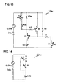
- FIG. 13 is a schematic diagram of another embodiment of a backlight drive circuit
- FIG. 14 is a schematic diagram of another embodiment of a backlight drive circuit
- FIG. 15 is a schematic diagram of another embodiment of a backlight drive circuit
- FIG. 16 is a schematic diagram of another embodiment of a backlight drive circuit
- FIG. 17 is a schematic diagram of another embodiment of a backlight drive circuit.
- FIG. 18 is a schematic diagram of another embodiment of a backlight drive circuit.
- FIG. 1 is a side view of a bicycle that includes particular embodiments of illumination-controlled devices.
- This bicycle is a light roadster recreational bicycle comprising a frame 1 having a double-loop frame body 2 formed from welded tubes, a front fork 3 mounted to the frame body 2 for rotation around a diagonal axis, a handle component 4 , a drive component 5 , a front wheel 6 on which a dynamo hub 8 with brakes is mounted, a rear wheel 7 on which an internal shifting hub 10 is mounted, a saddle 11 , a shift control unit 12 to control shifting of the internal shifting hub 10 , and a shift controller 20 for manually operating the shift control unit 12 .
- a tail light 18 b is mounted on the rear of frame body 2 .
- the handle component 4 comprises a handle stem 14 , fastened to the upper part of the front fork 3 , and a handlebar 15 fastened to the handle stem 14 .
- Brake levers 16 and grips 17 are mounted on both ends of the handlebar 15 .
- the shift controller 20 is integrated with the right-side brake lever 16 .
- the drive component 5 comprises a crank 37 , mounted on the lower part (bottom bracket component) of the frame body 2 , and a chain 38 that engages the crank 37 and the internal shifting hub 10 .
- the internal shifting hub 10 is capable of producing three speed steps, including a low speed step (speed 1), an intermediate speed step (speed 2), and a high speed step (speed 3). These three speed steps can be selected by means of a motor unit 29 ( FIG.
- the dynamo hub 8 of the front wheel 6 can be fitted with a roller-type front brake, and it houses an alternating current dynamo 19 ( FIG. 6 ) that generates electricity in response to the rotation of the front wheel 6 .
- the shift control unit 12 is electrically connected to the alternating current dynamo 19 housed in the dynamo hub 8 by electrical wiring 40 , and it is electrically connected to the shift controller 20 by electrical wiring 41 . Placing the dynamo 19 within hub 8 reduces pedaling resistance because the dynamo is mounted near the hub axle.
- the shift control unit 12 is mechanically connected to the internal shifting hub 10 by a shift control cable 42 .
- the shift control unit 12 comprises a headlight case 13 mounted to a headlight stay 3 a located midway along the front fork 3 for housing a headlight 18 a .
- the motor unit 29 and a circuit unit 30 are housed in the headlight case 13 .
- the motor unit 29 comprises an electric shifting motor 45 , a cable operating component 46 which moves into three shifting positions by means of the shifting motor 45 , and a position sensor 47 ( FIG. 6 ) to detect the shift position of the cable operating component 46 .
- One end of the shift control cable 42 is connected to this cable operating component 46 .
- This arrangement facilitates waterproof construction, since no electrical wires are needed between the shift control unit 12 and the internal shifting hub 10 or headlight 18 a . Furthermore, all of these components are mounted to the front of the bicycle, where they do not interfere with riding.
- the circuit unit 30 comprises a control element 25 ( FIG. 6 ) containing a microcomputer comprising a CPU, RAM, ROM, and an I/O interface.
- the shift controller 20 comprises two operating buttons 21 and 22 in the form of triangular pushbuttons disposed next to each other, an operating dial 23 disposed above the operating buttons 21 and 22 , and a liquid crystal display device 24 disposed to the left of the operating dial 23 .
- the operating button 21 on the left side is for manually shifting from the low speed step to the intermediate speed step and to the high speed step.
- the operating button 22 on the right side is for manually shifting from the high speed step to the intermediate speed step and to the low speed step.
- the operating dial 23 is used for switching between a manual shifting mode (M), three automatic shifting modes (A 1 –A 3 ), and a parking mode (P) using five detent positions.
- the three automatic shifting modes (A 1 –A 3 ) are modes for automatically shifting the internal shifting hub 10 according to a bicycle speed signal derived from the alternating current dynamo 19 in a manner described below.
- the manual shifting mode (M) is a mode for manually shifting the internal shifting hub ( 10 ) using the operating buttons 21 and 22
- the parking mode (P) is a mode for locking the internal shifting hub ( 10 ).
- the three automatic shifting modes (A 1 –A 3 ) are designed to allow shift timing (i.e., the threshold speed values at which shifting will occur) to be automatically changed during upshifting (shifting from low speed to high speed) or downshifting (shifting from high speed to low speed).
- the speed threshold values for the various modes are shown in FIG. 7 .
- the upward and downward shift timings gradually decrease from automatic shifting mode (A 1 ) through automatic shifting mode (A 3 ) such that automatic shifting mode (A 1 ) shifts at the highest speed, and automatic shifting mode (A 3 ) shifts at the lowest speed.
- the spacing of the threshold values decreases from automatic shifting mode (A 1 ) to automatic shifting mode (A 3 ). It is usually preferable to set the shift controller to automatic shifting mode (A 2 ).
- the internal shifting hub 10 When automatic shifting mode (A 2 ) is selected, for example, the internal shifting hub 10 is upshifted from speed 1 to speed 2 when the bicycle speed reaches 12.7 km/h. Similarly, the internal shifting hub 10 is upshifted to speed 3 when the bicycle speed reaches 17.1 km/h. On the other hand, when the bicycle speed later falls to 15.6 km/h, the internal shifting hub 10 is downshifted to speed 2, and again downshifted to speed 1 when the bicycle speed falls to 11.5 km/h. Between upshift timing and downshift timing, downshift timing is set as the lower of the two to prevent chattering during shifting. For climbing hills, a mode may be set according to the steepness of the hill.
- FIG. 6 is a block diagram illustrating the structure of the overall bicycle control system. Heavy lines in FIG. 6 indicate lines carrying about 1 A of current, solid lines indicate lines carrying about 5 mA of current, and dotted lines indicate signal lines.
- Control element 25 is operatively coupled to an operating switch 26 (which schematically represents the operating dial 23 and operating buttons 21 and 22 in the shift controller 20 ); to the liquid crystal display device 24 ; to a light sensor 36 (illumination sensor) for controlling the headlight 18 a and tail light 18 b , the internal shifting hub 10 , and the liquid crystal display device 24 ; to a dynamo waveform shaping circuit 34 that generates a speed signal derived from the output of the alternating current dynamo 19 , to a motor driver 28 , to the position sensor 47 of the motor unit 29 , and to other input/output components.
- Control element 25 includes a threshold value memory 25 a that stores the threshold values shown in FIG. 7 .
- Control element 25 automatically controls shifting of the internal shifting hub 10 via motor driver 28 according to travel speed, and it controls the information displayed on the liquid crystal display device 24 disposed in the shift controller 20 .
- the control element 25 also controls headlight 18 a and tail light 18 b by turning them on when surrounding light conditions fall below a certain prescribed brightness, and by turning them off when surrounding light conditions are above the prescribed brightness.
- the liquid crystal display device 24 has a liquid crystal display unit 24 a , a backlight 24 b facing the liquid crystal display unit 24 a , and a backlight driver circuit 24 c for driving backlight 24 b .
- Liquid crystal display unit 24 a displays the current speed, the gearshift step and other information.
- the backlight 24 b uses an LED that is capable of illumination with seven colors, for example.
- the backlight 24 b is switched on with a first light intensity L 1 when the surrounding illumination is equal to or less than a predetermined brightness (e.g., 15 lux) and is switched off when the surrounding illumination equal to or greater than a predetermined brightness (e.g., 20 lux).
- a predetermined brightness e.g. 15 lux
- backlight 24 b may light up with a second light intensity L 2 greater than the first light intensity L 1 if brightness is below a predetermined level, and light up with the first light intensity L 1 if brightness is above a predetermined level. In this way, power consumption can be minimized while maintaining good visibility during operation.
- Backlight 24 b may be designed to light up for about 30 seconds, for example, when control button 21 or 22 is operated.
- Backlight driver circuit 24 c may be operated by 5 V DC electricity supplied by a DC power supply, i.e. storage element 32 , via power-saving circuit 31 and control element 25 .
- the DC voltage supplied by the power supply may fluctuate up and down by about 0.5 V when the motor 45 or other load turns on and off, during charging, and so on.
- FIG. 8 is a schematic diagram of a particular embodiment of a backlight driver circuit 24 c that operates well in such an environment.
- Backlight driver circuit 24 c comprises a current supply circuit 50 for supplying DC current to backlight 24 b ; a current limiting circuit 51 for limiting current supplied to backlight 24 b to a constant level; a light intensity switching circuit 52 for switching the light intensity of backlight 24 b between two levels, and an on/off control circuit 53 for selectively turning backlight 24 b on and off.
- Current supply circuit 50 comprises a first bipolar transistor Q 1 and a first resistor R 1 .
- Transistor Q 1 is connected between the power source and backlight 24 b , and resistor R 1 is connected to the base terminal of transistor Q 1 for properly biasing transistor Q 1 .
- Current limiting circuit 51 comprises a second bipolar transistor Q 2 , two serially connected second resistors R 2 a and R 2 b , and a seventh resistor R 7 .
- the emitter terminal of transistor Q 2 is connected to the power supply, the collector terminal of transistor Q 2 is connected to a node between the base terminal of transistor Q 1 and resistor R 1 , and the base terminal of transistor Q 2 is connected to one terminal of resistor R 7 .
- the other terminal of resistor R 7 is connected to a node between resistor R 2 b and the emitter terminal of transistor Q 1 .
- the terminal of resistor R 2 a opposite resistor R 2 b is connected to the power supply.
- Resistor R 7 will prevent excessive base current from flowing through the base terminal of transistor Q 2 and possibly damaging transistor Q 2 in case resistor R 2 a and/or R 2 b malfunctions.
- Light intensity switching circuit 52 comprises resistors R 2 a , R 2 b and a third bipolar transistor Q 3 .
- the emitter terminal of transistor Q 3 is connected to the power supply, and the collector terminal of transistor Q 3 is connected to a node between resistor R 2 a and R 2 b .
- On/off control circuit 53 comprises a fourth bipolar transistor Q 4 and a fifth resistor R 5 .
- the collector terminal of transistor Q 4 is connected to the terminal of resistor R 1 opposite the base terminal of transistor Q 1 , and the emitter terminal of transistor Q 4 is connected to the negative side of the power supply.
- One terminal of resistor R 5 is connected to the positive side of the power supply, and the other terminal of resistor R 5 is connected to a node between resistor R 1 and the base terminal of transistor Q 1 .
- Resistor R 5 is provided to ensure that transistor Q 1 turns completely off when the transistor Q 4 turns off.
- Backlight drive circuit 24 c takes advantage of the characteristic of bipolar transistors to turn on when the voltage drop V be across the base and emitter of the bipolar transistor reaches approximately 0.6 V. More specifically, when the power supply voltage V dc is dropped at the node between resistors R 1 and R 5 so that V be (Q 1 ) reaches approximately 0.6 V, then transistor Q 1 turns on so that current flows to backlight 24 b . Similarly, when the power supply voltage V dc is dropped at the base terminal of transistor Q 2 by resistors R 2 a , R 2 b and R 7 (assuming transistor Q 3 is turned off) so that V be (Q 2 ) reaches approximately 0.6 V, then transistor Q 2 turns on.
- the voltage V b at the base terminal of transistor Q 2 will be equal to V dc ⁇ V be .
- the voltage drop across any of the resistances R 2 a , R 2 b and R 7 will remain constant despite any fluctuation in the power supply voltage.
- the voltage drop across resistances R 2 a and R 2 b determines the current supplied to backlight 24 b
- the current supplied to backlight 24 b also will remain constant despite any fluctuation in the power supply voltage.
- constant current control can be carried out relatively inexpensively using bipolar transistors, deviation in current limit value is less than when field effect transistors are used, and current limit value can be set fairly high.
- the light intensity of backlight 24 b can be switched between two levels by selectively turning transistor Q 3 on and off. More specifically, when the transistor Q 3 turns on, only the resistance value of resistor R 2 b is applied to the operation of backlight 24 b , thus causing the backlight 24 b to light at second light intensity L 2 . When transistor Q 3 is turned off, the sum of resistance values of the resistors R 2 a , R 2 b (R 2 a +R 2 b ) is applied to the operation of backlight 24 b , thus causing backlight 24 b to light at light intensity L 1 which is lower than light intensity L 2 .
- Light intensity switching circuit 52 and on/off control circuit 53 can be operated by signals from auto light circuit 35
- a charging control circuit 33 , a power storage element 32 (e.g., a capacitor), and an auto light circuit 35 are operatively coupled to the control element 25 via a power-saving circuit 31 .
- a signal from the alternating current dynamo 19 is input to the power-saving circuit 31 , and it is determined based on this signal whether or not the bicycle is stopped.
- the power saving circuit 31 supplies the control element 25 , the motor driver 28 , the charging control circuit 33 and the auto light circuit 35 with electrical power stored by the power storage element 32 when the bicycle is moving for the normal operation of these components, and it interrupts the supply of electrical power to these components when the bicycle is stopped to avoid needless expenditure of electrical power stored by the power storage element 32 .
- Motor driver 28 operates on a 1 mA current supplied by the power-saving circuit 31 , and it controls a 1 A current supplied by the power storage element 32 to operate the shifting motor 45 .
- the charging control circuit 33 comprises, for example, a half-wave rectifier circuit that rectifies an alternating current output from the alternating current dynamo 19 to 1 A and 5 mA direct currents (for example).
- the power storage element may 32 comprise, for example, a high-capacity capacitor that stores the direct current power that is output from the charging control circuit 33 .
- the power storage element 32 also may comprise secondary batteries such as nickel cadmium batteries, lithium ion batteries, nickel-metal hydride batteries, etc., in lieu of a capacitor.
- the dynamo waveform shaping circuit 34 forms a speed signal from the alternating current output from the alternating current dynamo 19 . More specifically, a half-cycle is extracted from a sine wave alternating current signal, passed through a Schmitt circuit or other appropriate waveform shaping circuit, and formed into a pulse signal corresponding to speed. Control element 25 uses this signal to control the automatic shifting of the internal shifting hub 10 without requiring a separate speed sensor.
- the auto light circuit 35 supplies or interrupts the 1 A current output from the alternating current dynamo 19 to the headlight 18 a and tail light 18 b in response to on/off signal output from the control element 25 .
- Control element 25 generates these signals based on the signals from the light sensor 36 in such a maimer that headlight 18 a and tail light 18 b are switched on automatically when light levels fall below a prescribed limit, and are is switched off when light levels exceed the prescribed limit.
- headlight 18 a and tail light 18 b are operated from the alternating current dynamo 19 so that the current draw is less apt to adversely affect the power storage element 32 , but this is not necessary.
- Battery replacement and recharging are unnecessary because the power storage element 32 stores electrical power from the alternating current dynamo 19 , and components such as the control element 25 are operated using this electrical power. Monitoring remaining battery power and carrying along spare batteries also become unnecessary, and shifting can be done automatically without performing the cumbersome procedures required by conventional power sources.
- the electrical power from the alternating current dynamo 19 which conventionally is not employed in the daytime, can be put to effective use in the shift control unit 12 .
- Bicycle speed is detected based on the alternating current signal output from the alternating current dynamo 19 , and shifting is controlled according to the detected bicycle speed.
- alternating current dynamos generally have a plurality of circumferentially disposed magnetic poles
- the alternating current dynamo outputs an alternating current signal with a frequency related to the bicycle speed and the number of magnetic poles. Consequently, it is possible to obtain a larger number of signal pulses from the alternating current signal during each wheel rotation in comparison with a speed signal obtainable, for example, from a conventional speed sensor that detects a magnet mounted to the bicycle wheel. Therefore, the bicycle speed can be accurately detected within the space of one wheel rotation, and shifting can be controlled in real time with high precision. Furthermore, since shifting is controlled based on the alternating current signal from the alternating current dynamo 19 , it is no longer necessary to dispose the shift control unit 12 in the vicinity of the bicycle wheel. No limitation is placed on the mounting position of the shift control unit 12 .
- control element 25 may be understood from the flowcharts shown in FIGS. 9–12 .
- the settings are initialized in step S 1 of FIG. 9 .
- the wheel circumference for calculating the bicycle speed may be set to a diameter of 26 inches, and all process flags are reset.
- a night flag NF is provided for discriminating between day and night.
- the night flag NF is set to ON when the surrounding illumination IL is 15 lux or less, and it is set to OFF when the surrounding illumination is 20 lux or greater. More specifically, the illumination IL is read from the light sensor 36 in step S 2 .
- step S 3 If it is determined in step S 3 that the night flag NF is already set to ON, then the process moves from step S 3 to step S 6 .
- step S 6 a determination is made whether or not the illumination IL is 20 lux or greater. If the illumination IL is 20 lux or greater, then the process moves to step S 7 and the night flag NF is set to OFF. If the illumination IL is less than 20, then step S 7 is skipped and the process moves to step S 8 .
- step S 8 a display processing routine shown in FIG. 10 is performed.
- step S 9 a determination is made whether or not the operating dial 23 has been set to the parking mode (P). If so, then the process moves from step S 9 to step S 15 to perform a parking processing routine. If not, then a determination is made in step S 10 whether or not the operating dial 23 has been set to the automatic shifting mode (A 1 ). If so, then the process moves from step S 10 to step S 16 to perform automatic shifting mode (A 1 ) processing shown in FIG. 11 . If not, then a determination is made in step S 11 whether or not the operating dial 23 has been set to the automatic shifting mode (A 2 ).
- step S 11 the process moves from step S 11 to step S 17 to perform automatic shifting mode (A 2 ) processing that is similar to automatic shift mode (A 1 ) processing. If not, then a determination is made in step S 12 whether or not the operating dial 23 has been set to the automatic shifting mode (A 3 ). If so, then the process moves from step S 12 to step S 18 to perform automatic shifting mode (A 3 ) processing that is similar to automatic shift mode (A 1 ) processing. If not, then a determination is made in step S 13 whether or not the operating dial 23 has been set to the manual mode (M). If so, then the process moves from step S 13 to step S 19 to perform manual mode (M) processing shown in FIG. 12 . If not, then a determination is made in step S 14 whether or not tire diameter input or some other processing has been selected. If so, then such other processing is performed in step S 20 .
- the night flag NF is set to ON (i.e., it is nighttime)
- step S 22 determines whether or not backlight 24 b , headlight 18 a and tail light 18 b are lighted. If so, then the process moves to step S 23 , various types of display processing are performed, and the process returns to the main routine. If not, then the process moves to steps S 28 and S 29 , backlight 24 b is lit to intensity L 1 , headlight 18 a and tail light 18 b are lighted, and the process moves to step S 23 .
- the night flag NF is on, then backlight 24 b is illuminated dimly.
- the light intensity of backlight 24 b is reduced even at night so that power consumption is further reduced.
- step S 21 If it is determined in step S 21 that the night flag NF is set to OFF (i.e., it is daytime), the process moves from step S 21 to step S 25 , and a determination is made whether or not backlight 24 b , the headlight 18 a and tail light 18 b are turned off. If so, then the process moves to step S 23 . If not, then the process moves to steps S 26 and S 27 , backlight 24 b , headlight 18 a and tail light 18 b are turned off, and the process moves to step S 23 .
- headlight 18 a and tail light 18 b are set in accordance with the surrounding illumination, for example, it is easy to visually confirm various types of information in conjunction with the surrounding conditions, and various types of information can be displayed under advantageous display conditions on the liquid crystal display 24 a.
- step S 15 the internal shifting hub 10 is set in a locked state, and code registration processing for registering a code that releases the locked state of the internal shifting hub 10 , code input processing for releasing the locked state, code verification processing for performing a verification, and other types of processing are executed in accordance with the operation of the operating buttons 21 and 22 .
- a gear position value VP is set to the gear position that corresponds to the bicycle speed S.
- the internal shifting hub 10 is shifted in the appropriate direction one step at a time. More specifically, the gear position value VP is read from the position sensor 47 in step S 31 , and the current bicycle speed S is determined from the speed signal from the alternating current dynamo 19 in step S 32 .
- step S 33 a determination is made whether or not the bicycle speed S exceeds the upshift threshold value U (VP) ( FIG. 7 ) that corresponds to the gear position value VP.
- a determination is made whether or not the bicycle speed S is less than the downshift threshold value D (VP) that corresponds to the gear position value VP.
- step S 33 If the current bicycle speed S exceeds the upshift threshold value U (VP) that corresponds to the current gear position shown in FIG. 7 , then the process moves from step S 33 to step S 35 .
- step S 35 a determination is made whether or not the gear position corresponds to third gear. If so, then the process moves to step S 34 without any processing because shifting higher than this is not possible. If the gear position is less than third gear, then the process moves to step S 36 , the gear position value VP is increased by one in order to upshift the internal shifting hub by one step, and the process moves to step S 34 .
- step S 34 If the current bicycle speed S is below the downshift threshold value D (VP) that corresponds to the current gear position shown in FIG. 7 , then the process moves from step S 34 to step S 37 .
- step S 37 a determination is made whether or not the gear position is first gear. If the gear position is first gear, then the process returns to the main routine without any further processing. If the gear position is equal to or greater than second gear, then the process moves to step S 38 , the gear position value VP is lowered by one in order to downshift the internal shifting hub 10 by one step, and the process returns to the main routine.
- step S 17 in FIG. 9 The automatic shifting mode (A 2 ) processing of step S 17 in FIG. 9 as well as the automatic shifting mode (A 3 ) processing of step S 18 are similar to automatic shifting mode (A 1 ) processing except for the use of different threshold values. Accordingly, a detailed description of those processes will be omitted.
- the internal shifting hub 10 is shifted one step at a time by the operation of the operating buttons 21 and 22 . More specifically, the gear position value VP is read from position sensor 47 in step S 51 . In step S 52 , a determination is made whether or not the operating button 21 has been operated, and in step S 53 , a determination is made whether or not the operating button 22 has been operated. If the operating button 21 has been operated, then the process moves from step S 52 to S 54 , and a determination is made whether or not the night flag NF is on (i.e., whether it is night time).
- step S 54 If it is daytime, then the process moves from step S 54 to step S 55 , wherein backlight (BL) 24 b is turned on at light intensity L 1 (dim light intensity). If it is nighttime, then the routine moves from step S 54 to step S 56 , wherein backlight 24 b is turned on at light intensity L 2 (bright light intensity). Backlight 24 b may be turned on for 30 seconds, for example. In other words, in step S 55 transistor Q 4 in on/off control circuit 53 is turned on for 30 seconds, and in step S 56 transistor Q 4 in on/off control circuit 53 is turned on for 30 seconds and transistor Q 3 in light intensity switching circuit 52 also is turned on for 30 seconds.
- step S 57 it is determined from the current gear position value VP whether or not the internal shifting hub 10 is in third gear. If the internal shifting hub 10 is not in third gear, then the process moves to step S 58 wherein the gear position value VP is incremented by one gear position and the internal shifting hub 10 is upshifted accordingly. If the internal shifting hub 10 currently is in third gear, then this processing is skipped.
- step S 53 If the operating button 22 has been operated, then the process moves from step S 53 to S 60 .
- steps S 60 –S 62 a backlight control process analogous to that of steps S 54 –S 56 is performed.
- step S 63 a determination is made from the current gear position value VP whether or not the internal shifting hub 10 is in first gear. If the internal shifting hub 10 is not in first gear, then the process moves to step S 64 , the gear position value VP is decreased by one gear position and the internal shifting hub 10 is downshifted accordingly. If the internal shifting hub 10 currently is in first gear, then this processing is skipped.
- the ON/OFF state of the backlight 24 b is controlled in the present embodiment in accordance with daytime and nighttime, and backlight 24 b also lights up in response to the operation of operating buttons 21 and 22 .
- various types of information can be displayed advantageously in conjunction with the surrounding conditions, and inputs can be verified reliably.
- resistors R 2 a , R 2 b in backlight drive circuit 24 c were serially connected.
- resistors R 2 a , R 2 b could be connected in parallel, with the transistor Q 3 connected in series with resistor R 2 b.
- backlight drive circuit 224 c could be constructed using an N or P channel field effect transistor J 1 .
- This arrangement utilizes the ability of the junction field effect transistor to allow maximum current flow when the potential difference across the gate and source terminals is zero, and to set current to a predetermined value in response to a selected potential difference across the gate and source terminals.
- a resistance R 6 disposed between the gate and source terminals creates a predetermined potential difference across the gate and source terminals, thus limiting the electrical current flowing between the drain and source terminals.
- the current supply circuit and current limiting circuit can be realized as a single element, whereby fluctuations in current flowing to backlight 24 b can be reduced with a small number of components.
- backlight drive circuit 324 c could be constructed using NPN or PNP bipolar transistors Q 1 , Q 2 without performing on/off or light intensity switching.
- the architecture and operation in this case will be analogous to that in the preceding embodiment and need not be described here.
- a backlight 24 b for a liquid display device 24 is described by way of an exemplary lighting device.
- the circuitry could be used with other lighting devices such as headlight or tail light 18 b , for example.
- an LED was used as an exemplary light source, but a bulb with a filament could be used instead.
- a signal of about 60 Hz could be applied from a pulse wave modulation (PWM) circuit to the base terminal of transistor Q 4 in the on/off control circuit of a drive circuit 424 c shown in FIG. 18 .
- PWM pulse wave modulation
- the light intensity of the light source will be lower due to being normally on, but the on/off ratio (duty ratio) of the PWM circuit can be varied to adjust light intensity so as to give relatively good energy efficiency.
- a circuit for switching light intensity between two levels is not provided in this embodiment.
Applications Claiming Priority (2)
| Application Number | Priority Date | Filing Date | Title |
|---|---|---|---|
| JP2002-205721 | 2002-07-15 | ||
| JP2002205721A JP3654876B2 (ja) | 2002-07-15 | 2002-07-15 | 自転車用照明装置駆動装置 |
Publications (2)
| Publication Number | Publication Date |
|---|---|
| US20040051375A1 US20040051375A1 (en) | 2004-03-18 |
| US7119707B2 true US7119707B2 (en) | 2006-10-10 |
Family
ID=29774591
Family Applications (1)
| Application Number | Title | Priority Date | Filing Date |
|---|---|---|---|
| US10/618,343 Expired - Fee Related US7119707B2 (en) | 2002-07-15 | 2003-07-10 | Circuit for providing electrical current to a bicycle device |
Country Status (5)
| Country | Link |
|---|---|
| US (1) | US7119707B2 (zh) |
| EP (1) | EP1383223B1 (zh) |
| JP (1) | JP3654876B2 (zh) |
| CN (1) | CN1276860C (zh) |
| TW (1) | TW590932B (zh) |
Cited By (1)
| Publication number | Priority date | Publication date | Assignee | Title |
|---|---|---|---|---|
| US20070252537A1 (en) * | 2006-04-28 | 2007-11-01 | Shimano Inc. | Bicycle lighting system |
Families Citing this family (17)
| Publication number | Priority date | Publication date | Assignee | Title |
|---|---|---|---|---|
| DE102004013981A1 (de) * | 2004-03-19 | 2005-10-06 | Busch & Müller KG | Verfahren und Vorrichtung zum Betrieb einer Leuchtdiode mit dem Dynamo eines Zweirades |
| EP1891728B1 (en) * | 2005-02-17 | 2016-08-17 | Reelight APS | An electric converter system comprising storage media having different storing capacities |
| DE502005008051D1 (de) * | 2005-07-12 | 2009-10-15 | Shimano Kk | Beleuchtungsvorrichtung für ein Fahrrad mit zusätzlichem elektrischen Ausgang |
| CA2930483C (en) | 2005-12-09 | 2017-11-07 | Fallbrook Intellectual Property Company Llc | Continuously variable transmission |
| EP1811202A1 (en) | 2005-12-30 | 2007-07-25 | Fallbrook Technologies, Inc. | A continuously variable gear transmission |
| US7882762B2 (en) | 2006-01-30 | 2011-02-08 | Fallbrook Technologies Inc. | System for manipulating a continuously variable transmission |
| JP2009104792A (ja) * | 2007-10-19 | 2009-05-14 | Kawamura Electric Inc | 停電用保安灯 |
| WO2009065055A2 (en) | 2007-11-16 | 2009-05-22 | Fallbrook Technologies Inc. | Controller for variable transmission |
| JP2009152518A (ja) * | 2007-11-30 | 2009-07-09 | Omron Corp | 発光ダイオード駆動装置 |
| CN102317146B (zh) | 2007-12-21 | 2015-11-25 | 福博科知识产权有限责任公司 | 自动传动装置及用于其的方法 |
| WO2010017242A1 (en) | 2008-08-05 | 2010-02-11 | Fallbrook Technologies Inc. | Methods for control of transmission and prime mover |
| DE102012107525A1 (de) | 2012-08-16 | 2014-02-20 | Phoenix Contact Gmbh & Co. Kg | Sicherungsausfallanzeige |
| TWI549567B (zh) * | 2015-06-24 | 2016-09-11 | 技嘉科技股份有限公司 | 智慧型自行車燈的節電方法 |
| US10047861B2 (en) | 2016-01-15 | 2018-08-14 | Fallbrook Intellectual Property Company Llc | Systems and methods for controlling rollback in continuously variable transmissions |
| US10023266B2 (en) | 2016-05-11 | 2018-07-17 | Fallbrook Intellectual Property Company Llc | Systems and methods for automatic configuration and automatic calibration of continuously variable transmissions and bicycles having continuously variable transmissions |
| US11215268B2 (en) | 2018-11-06 | 2022-01-04 | Fallbrook Intellectual Property Company Llc | Continuously variable transmissions, synchronous shifting, twin countershafts and methods for control of same |
| US11174922B2 (en) | 2019-02-26 | 2021-11-16 | Fallbrook Intellectual Property Company Llc | Reversible variable drives and systems and methods for control in forward and reverse directions |
Citations (9)
| Publication number | Priority date | Publication date | Assignee | Title |
|---|---|---|---|---|
| US4379237A (en) * | 1981-09-17 | 1983-04-05 | Mosteller Jr Lawson P | Light intensity control device and circuit therefor |
| DE3146328A1 (de) | 1981-11-23 | 1983-06-01 | Siemens AG, 1000 Berlin und 8000 München | Leuchtdiodenvorrichtung mit schutzeinrichtung zur begrenzung des durchlassstroms |
| GB2126438A (en) | 1982-02-10 | 1984-03-21 | Vincent Joseph Skinner | Lighting system for cycles |
| US4727308A (en) | 1986-08-28 | 1988-02-23 | International Business Machines Corporation | FET power converter with reduced switching loss |
| DE3832109A1 (de) | 1988-09-21 | 1990-03-22 | Juergen Munz | Leuchte |
| US5818172A (en) * | 1994-10-28 | 1998-10-06 | Samsung Electronics Co., Ltd. | Lamp control circuit having a brightness condition controller having 2.sup.nrd and 4th current paths |
| FR2763203A1 (fr) | 1997-05-09 | 1998-11-13 | Schneider Electric Sa | Circuit electrique d'alimentation d'une diode electroluminescente |
| US5998928A (en) * | 1997-11-03 | 1999-12-07 | Ford Motor Company | Lighting intensity control system |
| DE19948798A1 (de) | 1998-10-10 | 2001-05-10 | Norman Gerkinsmeyer | Integriertes Fahrradbeleuchtungssystem |
Family Cites Families (2)
| Publication number | Priority date | Publication date | Assignee | Title |
|---|---|---|---|---|
| JPS5687384A (en) * | 1979-12-18 | 1981-07-15 | Fujitsu Ltd | Light emitting diode type display lamp |
| JPH073887B2 (ja) * | 1985-07-03 | 1995-01-18 | 株式会社日立製作所 | 発光ダイオ−ド駆動回路 |
-
2002
- 2002-07-15 JP JP2002205721A patent/JP3654876B2/ja not_active Expired - Fee Related
-
2003
- 2003-06-10 TW TW092115732A patent/TW590932B/zh not_active IP Right Cessation
- 2003-07-10 US US10/618,343 patent/US7119707B2/en not_active Expired - Fee Related
- 2003-07-14 CN CNB031476023A patent/CN1276860C/zh not_active Expired - Fee Related
- 2003-07-15 EP EP03016085A patent/EP1383223B1/en not_active Expired - Lifetime
Patent Citations (9)
| Publication number | Priority date | Publication date | Assignee | Title |
|---|---|---|---|---|
| US4379237A (en) * | 1981-09-17 | 1983-04-05 | Mosteller Jr Lawson P | Light intensity control device and circuit therefor |
| DE3146328A1 (de) | 1981-11-23 | 1983-06-01 | Siemens AG, 1000 Berlin und 8000 München | Leuchtdiodenvorrichtung mit schutzeinrichtung zur begrenzung des durchlassstroms |
| GB2126438A (en) | 1982-02-10 | 1984-03-21 | Vincent Joseph Skinner | Lighting system for cycles |
| US4727308A (en) | 1986-08-28 | 1988-02-23 | International Business Machines Corporation | FET power converter with reduced switching loss |
| DE3832109A1 (de) | 1988-09-21 | 1990-03-22 | Juergen Munz | Leuchte |
| US5818172A (en) * | 1994-10-28 | 1998-10-06 | Samsung Electronics Co., Ltd. | Lamp control circuit having a brightness condition controller having 2.sup.nrd and 4th current paths |
| FR2763203A1 (fr) | 1997-05-09 | 1998-11-13 | Schneider Electric Sa | Circuit electrique d'alimentation d'une diode electroluminescente |
| US5998928A (en) * | 1997-11-03 | 1999-12-07 | Ford Motor Company | Lighting intensity control system |
| DE19948798A1 (de) | 1998-10-10 | 2001-05-10 | Norman Gerkinsmeyer | Integriertes Fahrradbeleuchtungssystem |
Non-Patent Citations (3)
| Title |
|---|
| "Power Control For Battery-Electric Bicycles," Aerospace & Electronics Conference, 1993; NAECON 1993; Proceedings of the IEEE 1993 National, Dayton, OH, USA, May 24-28, 1993, New York, NY, USA, IEEE, US, May 24, 1993, pp. 428-434, XP010115980, ISBN: 0-7803-1295-3. |
| Patent Abstracts of Japan, vol. 11, No. 174 (E-513), Jun. 4, 1987; for JP 62-007175 A (Hitachi Ltd.), published Jan. 14, 1987. |
| Patent Abstracts of Japan, vol. 5, No. 159 (E-077), Oct. 14, 1981; for JP 56-087384 A (Fujitsu Ltd.), published Jul. 15, 1981. |
Cited By (2)
| Publication number | Priority date | Publication date | Assignee | Title |
|---|---|---|---|---|
| US20070252537A1 (en) * | 2006-04-28 | 2007-11-01 | Shimano Inc. | Bicycle lighting system |
| US7459857B2 (en) * | 2006-04-28 | 2008-12-02 | Shimano Inc. | Bicycle lighting system |
Also Published As
| Publication number | Publication date |
|---|---|
| EP1383223A3 (en) | 2004-07-07 |
| CN1475391A (zh) | 2004-02-18 |
| CN1276860C (zh) | 2006-09-27 |
| JP2004042850A (ja) | 2004-02-12 |
| US20040051375A1 (en) | 2004-03-18 |
| TW590932B (en) | 2004-06-11 |
| TW200400894A (en) | 2004-01-16 |
| EP1383223A2 (en) | 2004-01-21 |
| JP3654876B2 (ja) | 2005-06-02 |
| EP1383223B1 (en) | 2012-04-11 |
Similar Documents
| Publication | Publication Date | Title |
|---|---|---|
| US7119668B2 (en) | Illumination-controlled bicycle devices | |
| US7119707B2 (en) | Circuit for providing electrical current to a bicycle device | |
| US7165641B2 (en) | Bicycle power supply with discharge function | |
| US6959939B2 (en) | Electronic bicycle shift control device | |
| US7311322B2 (en) | Bicycle control apparatus that sets a bicycle transmission to a predetermined gear ratio | |
| USRE43562E1 (en) | Bicycle shift control apparatus that prevents undesirable chain angles | |
| US7288038B2 (en) | Bicycle shift control apparatus with preferential shifting | |
| US6418041B1 (en) | Bicycle power supply | |
| US6959941B2 (en) | Bicycle shift control apparatus that selectively restricts speed stages | |
| US7045910B2 (en) | Bicycle power supply with reduced battery leakage | |
| JP2004175259A (ja) | 自転車用電子制御装置 | |
| JP4065275B2 (ja) | 自転車用変速システム |
Legal Events
| Date | Code | Title | Description |
|---|---|---|---|
| AS | Assignment |
Owner name: SHIMANO, INC., JAPAN Free format text: ASSIGNMENT OF ASSIGNORS INTEREST;ASSIGNOR:UNO, KOUJI;REEL/FRAME:014631/0375 Effective date: 20031027 |
|
| FPAY | Fee payment |
Year of fee payment: 4 |
|
| FPAY | Fee payment |
Year of fee payment: 8 |
|
| FEPP | Fee payment procedure |
Free format text: MAINTENANCE FEE REMINDER MAILED (ORIGINAL EVENT CODE: REM.) |
|
| LAPS | Lapse for failure to pay maintenance fees |
Free format text: PATENT EXPIRED FOR FAILURE TO PAY MAINTENANCE FEES (ORIGINAL EVENT CODE: EXP.); ENTITY STATUS OF PATENT OWNER: LARGE ENTITY |
|
| STCH | Information on status: patent discontinuation |
Free format text: PATENT EXPIRED DUE TO NONPAYMENT OF MAINTENANCE FEES UNDER 37 CFR 1.362 |
|
| FP | Lapsed due to failure to pay maintenance fee |
Effective date: 20181010 |