US7076986B2 - Process for forming a linking element for a push belt for a continuously variable transmission - Google Patents
Process for forming a linking element for a push belt for a continuously variable transmission Download PDFInfo
- Publication number
- US7076986B2 US7076986B2 US10/867,454 US86745404A US7076986B2 US 7076986 B2 US7076986 B2 US 7076986B2 US 86745404 A US86745404 A US 86745404A US 7076986 B2 US7076986 B2 US 7076986B2
- Authority
- US
- United States
- Prior art keywords
- linking element
- push belt
- blanking
- linking
- central portion
- Prior art date
- Legal status (The legal status is an assumption and is not a legal conclusion. Google has not performed a legal analysis and makes no representation as to the accuracy of the status listed.)
- Expired - Lifetime
Links
- 238000000034 method Methods 0.000 title claims abstract description 54
- 230000008569 process Effects 0.000 title claims abstract description 53
- 230000005540 biological transmission Effects 0.000 title claims abstract description 13
- 239000000463 material Substances 0.000 claims abstract description 37
- 238000007493 shaping process Methods 0.000 claims abstract description 14
- 238000003825 pressing Methods 0.000 claims 1
- 238000005520 cutting process Methods 0.000 description 41
- 238000005452 bending Methods 0.000 description 10
- 230000007704 transition Effects 0.000 description 8
- 238000013461 design Methods 0.000 description 7
- 230000004308 accommodation Effects 0.000 description 5
- 239000012141 concentrate Substances 0.000 description 3
- 238000011161 development Methods 0.000 description 3
- 230000000694 effects Effects 0.000 description 3
- 239000000969 carrier Substances 0.000 description 2
- 230000001186 cumulative effect Effects 0.000 description 2
- 230000001419 dependent effect Effects 0.000 description 2
- 230000003993 interaction Effects 0.000 description 2
- 238000012545 processing Methods 0.000 description 2
- 230000008901 benefit Effects 0.000 description 1
- 238000006073 displacement reaction Methods 0.000 description 1
- 238000009826 distribution Methods 0.000 description 1
- 238000004519 manufacturing process Methods 0.000 description 1
- 238000012986 modification Methods 0.000 description 1
- 230000004048 modification Effects 0.000 description 1
Images


Classifications
-
- B—PERFORMING OPERATIONS; TRANSPORTING
- B21—MECHANICAL METAL-WORKING WITHOUT ESSENTIALLY REMOVING MATERIAL; PUNCHING METAL
- B21D—WORKING OR PROCESSING OF SHEET METAL OR METAL TUBES, RODS OR PROFILES WITHOUT ESSENTIALLY REMOVING MATERIAL; PUNCHING METAL
- B21D28/00—Shaping by press-cutting; Perforating
- B21D28/24—Perforating, i.e. punching holes
- B21D28/32—Perforating, i.e. punching holes in other articles of special shape
-
- B—PERFORMING OPERATIONS; TRANSPORTING
- B21—MECHANICAL METAL-WORKING WITHOUT ESSENTIALLY REMOVING MATERIAL; PUNCHING METAL
- B21D—WORKING OR PROCESSING OF SHEET METAL OR METAL TUBES, RODS OR PROFILES WITHOUT ESSENTIALLY REMOVING MATERIAL; PUNCHING METAL
- B21D53/00—Making other particular articles
- B21D53/14—Making other particular articles belts, e.g. machine-gun belts
-
- F—MECHANICAL ENGINEERING; LIGHTING; HEATING; WEAPONS; BLASTING
- F16—ENGINEERING ELEMENTS AND UNITS; GENERAL MEASURES FOR PRODUCING AND MAINTAINING EFFECTIVE FUNCTIONING OF MACHINES OR INSTALLATIONS; THERMAL INSULATION IN GENERAL
- F16G—BELTS, CABLES, OR ROPES, PREDOMINANTLY USED FOR DRIVING PURPOSES; CHAINS; FITTINGS PREDOMINANTLY USED THEREFOR
- F16G5/00—V-belts, i.e. belts of tapered cross-section
- F16G5/16—V-belts, i.e. belts of tapered cross-section consisting of several parts
-
- Y—GENERAL TAGGING OF NEW TECHNOLOGICAL DEVELOPMENTS; GENERAL TAGGING OF CROSS-SECTIONAL TECHNOLOGIES SPANNING OVER SEVERAL SECTIONS OF THE IPC; TECHNICAL SUBJECTS COVERED BY FORMER USPC CROSS-REFERENCE ART COLLECTIONS [XRACs] AND DIGESTS
- Y10—TECHNICAL SUBJECTS COVERED BY FORMER USPC
- Y10T—TECHNICAL SUBJECTS COVERED BY FORMER US CLASSIFICATION
- Y10T83/00—Cutting
- Y10T83/04—Processes
- Y10T83/0524—Plural cutting steps
- Y10T83/0529—Blanking and cutting
-
- Y—GENERAL TAGGING OF NEW TECHNOLOGICAL DEVELOPMENTS; GENERAL TAGGING OF CROSS-SECTIONAL TECHNOLOGIES SPANNING OVER SEVERAL SECTIONS OF THE IPC; TECHNICAL SUBJECTS COVERED BY FORMER USPC CROSS-REFERENCE ART COLLECTIONS [XRACs] AND DIGESTS
- Y10—TECHNICAL SUBJECTS COVERED BY FORMER USPC
- Y10T—TECHNICAL SUBJECTS COVERED BY FORMER US CLASSIFICATION
- Y10T83/00—Cutting
- Y10T83/04—Processes
- Y10T83/06—Blanking
-
- Y—GENERAL TAGGING OF NEW TECHNOLOGICAL DEVELOPMENTS; GENERAL TAGGING OF CROSS-SECTIONAL TECHNOLOGIES SPANNING OVER SEVERAL SECTIONS OF THE IPC; TECHNICAL SUBJECTS COVERED BY FORMER USPC CROSS-REFERENCE ART COLLECTIONS [XRACs] AND DIGESTS
- Y10—TECHNICAL SUBJECTS COVERED BY FORMER USPC
- Y10T—TECHNICAL SUBJECTS COVERED BY FORMER US CLASSIFICATION
- Y10T83/00—Cutting
- Y10T83/647—With means to convey work relative to tool station
- Y10T83/654—With work-constraining means on work conveyor [i.e., "work-carrier"]
- Y10T83/6563—With means to orient or position work carrier relative to tool station
Definitions
- the present invention relates to a process for forming a linking element which is designed to be part of a push belt for a continuously variable transmission.
- a push belt for a continuously variable transmission is generally known.
- Such a push belt usually comprises two bundles of endless bands being shaped like a closed loop, which are also indicated as rings, and which function as carriers of a relatively large number of linking elements or transverse elements.
- the linking elements are movably arranged along the entire circumference of the bands, wherein they are able to transmit forces which are related to a movement of the push belt during operation.
- a longitudinal direction of the linking element corresponds to a circumferential direction of the push belt.
- a vertical transverse direction of the linking element corresponds to a radial direction of the push belt.
- a horizontal transverse direction of the linking element corresponds to a direction perpendicular to both the longitudinal direction and the vertical transverse direction.
- the linking element is on both sides provided with recesses for at least partially receiving the bundles of bands.
- the linking element comprises carrying surfaces.
- the linking element is on both sides provided with pulley sheave contact surfaces, in the horizontal transverse direction, which are divergent in the direction of the carrying surfaces.
- the linking element comprises successively a basic portion, a neck portion of which the dimensions in the horizontal transverse direction are smaller than those of the basic portion, and a top portion of which the dimensions in the horizontal transverse direction at the location of the connection to the neck portion are larger than those of the neck portion.
- the basis portion comprises the carrying surfaces and the pulley sheave contact surfaces.
- the basic portion is located at the side of the inner circumference of the push belt, whereas the top portion is located at the side of the outer circumference of the push belt.
- An important function of the neck portion is interconnecting the basic portion and the top portion.
- the linking element has two main body surfaces, namely a front surface and a back surface, which extend substantially parallel with respect to each other, substantially perpendicular to the longitudinal direction. At least a part of the front surface of the linking element is designed to abut against at least a part of the back surface of a subsequent linking element in the push belt, whereas at least a part of the back surface of the linking element is designed to abut against at least a part of the front surface of a previous linking element in the push belt.
- two adjacent linking elements are tiltable with respect to each other about a tilting line, which is usually defined at the front surface of each linking element, and which extends along the entire width of the linking element.
- the tilting line is formed as a convex transition region at the front surface, which constitutes an even and round transition of two portions of the front surface, which are oriented at a relatively small angle with respect to each other.
- An important function of the tilting line is guaranteeing mutual contact between adjacent linking elements which during operation of the push belt are located between the pulley sheaves of a pulley.
- the tilting line is intended to arrange that the forces which are related to a movement of the push belt are transmitted from any linking element to a subsequent linking element in a controlled manner, accompanied by a surface pressure which is regarded as allowable, and which is among others determined by the width of the linking element, i.e. the length of the tilting line, and by the extent to which the convex transition region forming the tilting line is curved, so that undesirable very high local load of the linking elements when they are located in the mutually tilted position can be prevented, together with breakage of the linking elements.
- the linking element is manufactured from basic material being shaped like a sheet by means of a blanking process.
- a cutting member and a supporting member are applied, wherein the cutting member is designed to cut the linking element from the basic material under the influence of a cutting force, and wherein the supporting member is designed to support the linking element by a supporting force during the blanking process.
- the cutting member penetrates the basic material under the influence of pressure, wherein a mutual movement of the cut linking element and the basic material is allowed.
- the linking element is clamped between a cutting surface of the cutting member and a supporting surface of the supporting member.
- the front surface of the linking element is formed at the side of the supporting member, whereas the back surface is formed at the side of the cutting member. Due to the pressure being prevalent during the blanking process, the shape of the supporting surface is then a determining factor regarding the shape of the front surface of the linking element, whereas the shape of the cutting surface is a determining factor regarding the shape of the back surface of the linking element.
- a central portion of a main body surface of the linking element which is centrally located in the horizontal transverse direction, is somewhat thicker than other parts thereof, i.e. has a somewhat larger dimension in the longitudinal direction, wherein in the circumferential direction of the push belt, play is present in-between the linking elements, at side portions which are located on both sides of the central portion, underlies the present invention.
- a thicker central portion of the linking element comprises a central portion of the tilting line, wherein the central portion can also extend as far as in the neck portion.
- the pressure loads or pushing forces between adjacent linking elements as occurring during operation of the push belt will unintentionally concentrate themselves in the thicker central portion of the tilting line, contrary to an even pressure distribution along the entire length of the tilting line, which may be expected according to the design, so that the tension in the material of the linking elements may locally exceed beyond a theoretical design value.
- the pushing force between two linking elements which in first instance acts on the area of the thicker central portion, together with a friction force between the linking elements and the pulley sheaves, which always acts on the area of the pulley sheave contact surfaces, generates a torque, as a result of which the linking elements unexpectedly also experience flexural strain.
- the linking element shall be inclined to bend, such that the linking element assumes a position in which the pushing force does not only act on the area of the thicker central portion, but also on the area of the side portions.
- the play is very small, and is in an order of magnitude of about 10 ⁇ m. It would therefore be obvious to regard the thickened part of the central portion as negligible.
- the present invention is based on the insight that the thickened part of the central portion is still an important factor regarding the occurrence of breakage in the linking element, because the effect of the bending of the linking element is more or less cumulative, which means that an already bent linking element will have to bend further if this linking element abuts against a preceding linking element which is also bent itself as a result of the above-described interplay of forces.
- a first linking element in a series of adjacent and bent linking elements will then bend substantially, even if the extent to which the central portion is thickened is relatively small per linking element.
- the flexural strain and bending will vary during a revolution of the push belt, dependent on the pushing force, when the push belt is applied in a continuously variable transmission, as a result of which fatigue breakage may occur.
- the development of the thicker central portion is a consequence of the blanking process, which apparently manifests itself in an intensified manner as side effect of amendments and improvements of the blanking process, as generally are pursued.
- the present invention proposes to decrease the chance of breakage of the linking elements by adjusting the shape of the linking elements, namely such that it is assured that in the push belt, adjacent linking elements abut against each other at least at the side portions, so that bending about the central portion can not take place.
- the set objective can be achieved according to the present invention by adjusting the blanking tools with which the linking elements are formed and more in particular the cutting member and/or the supporting member, which can be established in different ways.
- a possibility is to adapt the blanking tools for displacing material from the central portion of the linking element under the influence of pressure during the blanking process.
- Another possibility is to adapt the blanking tools to exert relatively less pressure at the area of the side portions during the blanking process. Both measures prevent the development of a thickened central portion, and may be applied together.
- FIG. 1 is a diagrammatical side view of a continuously variable transmission having a push belt
- FIG. 2 is a front view of a linking element for a push belt for a continuously variable transmission
- FIG. 3 is a side view of the linking element which is shown in FIG. 2 ;
- FIG. 4 shows a diagrammatic longitudinal section of a blanking area of a blanking device, as well as basic material being positioned in there;
- FIG. 5 a diagrammatically shows a first stage of a blanking movement
- FIG. 5 b diagrammatically shows a second stage of the blanking movement
- FIG. 5 c diagrammatically shows a third stage of the blanking movement
- FIG. 5 d diagrammatically shows a fourth stage of the blanking movement
- FIG. 6 a is a top view of a number of adjacent linking elements being arranged according to a theoretical configuration
- FIG. 6 b is a top view of a number of adjacent linking elements being arranged according to a configuration which appears to occur in practice;
- FIG. 7 is a perspective view of a first preferred embodiment of a blanking member according to the invention.
- FIG. 8 is a perspective view of a second preferred embodiment of the blanking member according to the invention.
- FIG. 9 is a perspective view of a third preferred embodiment of the blanking member according to the invention.
- FIG. 10 is a perspective view of a fourth preferred embodiment of the blanking member according to the invention.
- FIG. 11 shows a first possibility of a top view of the blanking member which is shown in FIG. 10 ;
- FIG. 12 shows a second possibility of the top view of the blanking member which is shown in FIG. 10 ;
- FIG. 13 shows a third possibility of the top view of the blanking member which is shown in FIG. 10 ;
- FIG. 14 is a side view of a cross section of a linking element as it is located between blanking tools during a blanking process.
- FIG. 1 diagrammatically shows a continuously variable transmission, such as for utilization in a motor vehicle.
- the continuously variable transmission is indicated in general by the reference sign 1 .
- the continuously variable transmission 1 comprises two pulleys 4 , 5 being arranged on separate pulley shafts 2 , 3 .
- An endless push. belt 6 being shaped like a closed loop is arranged around the pulleys 4 , 5 and serves for transmitting torque between the pulley shafts 2 , 3 .
- the pulleys 4 , 5 are each provided with two pulley sheaves, wherein the push belt 6 is positioned and clamped between these two pulley sheaves, so that with the help of friction a force may be transmitted between the pulleys 4 , 5 and the push belt 6 .
- the push belt 6 comprises at least one endless carrier 7 , which is usually composed of a number of bands.
- Linking elements 10 are arranged along the entire length of the carrier 7 , wherein the linking elements 10 are mutually adjacent to each other and are movable in circumferential direction with respect to the carrier 7 . For the sake of simplicity, only a few of these linking elements 10 are shown in FIG. 1 .
- FIGS. 2 and 3 show a linking element 10 .
- a front surface of the linking element 10 is indicated in general by the reference sign 11
- a back surface of the linking element 10 is indicated in general by the reference sign 12 .
- both the front surface 11 and the back surface 12 are also indicated as main body surface 11 , 12 .
- the linking element 10 comprises successively a basic portion 13 , a relatively narrow neck portion 14 and a top portion 15 which is shaped like the tip of an arrow.
- the basic portion 13 is located at the side of the inner circumference of the push belt 6
- the top portion 15 is located at the side of the outer circumference of the push belt 6 .
- at least a part of the front surface 11 of the linking element 10 abuts against at least a part of the back surface 12 of a subsequent linking element 10
- at least a part of the back surface 12 of the linking element 10 abuts against at least a part of the front surface 11 of a preceding linking element 10 .
- the basic portion 13 of the linking element 10 as shown in FIG. 2 comprises two carrying surfaces 16 which serve for supporting two carriers 7 . Furthermore, the basic portion 13 comprises two pulley sheave contact surfaces 17 .
- the linking element 10 moves over the pulley 4 , 5 , contact between the linking element 10 and contact surfaces of the pulley sheaves is established through the pulley sheave contact surfaces 17 .
- a tilting line 18 is defined.
- the tilting line 18 is located at the basic portion 13 and extends in the shown example along the entire width of the linking element 10 .
- FIG. 3 it can be seen that in this example the tilting line 18 is located at the area where a slanting portion 19 of the front surface 11 of the linking element 10 is connected to a straight portion 20 of the front surface 11 .
- An important function of the tilting line 18 is guaranteeing mutual contact between adjacent linking elements 10 , when these linking elements 10 move over one of the pulleys 4 , 5 during a movement of the push belt 6 , for example.
- a projection 21 is arranged at the front surface 11 of the linking element 10 .
- the projection 21 is located at the top portion 15 , and corresponds to a hole in the back surface 12 .
- the hole is depicted by means of dashed lines and indicated by the reference sign 22 .
- the projection 21 of the linking element 10 is at least partially located inside the hole 22 of a subsequent linking element 10 .
- the projection 21 and the corresponding hole 22 serve to prevent mutual displacement of adjacent linking elements 10 in a plane perpendicular to the circumferential direction of the push belt 6 .
- the linking element 10 is manufactured by means of a blanking process, wherein a supporting member and a cutting member are applied.
- the supporting member serves to support the linking element during the blanking process
- the cutting member serves to cut the linking element from basic material being shaped like a sheet during-the blanking process.
- the front surface 11 of the linking element 10 is formed by a supporting surface of the supporting member, whereas the back surface 12 of the linking element 10 is formed by a cutting surface of the cutting member. That does not alter the fact that the invention also relates to the situation in which the front surface 11 is formed by the cutting surface and the back surface 12 is formed by the supporting surface.
- the circumference of both the supporting surface and the cutting surface has substantially the same shape as the circumference of the linking element 10 which has to be cut, wherein these surfaces, like the linking element 10 , comprise a basic portion, a relatively narrow neck portion and a top portion which is shaped like the tip of an arrow.
- a vertical height corresponds to the direction in which the basic portion, the neck portion and the top portion are successively located.
- a longitudinal direction corresponds to a direction perpendicular to the supporting surface and the cutting surface, respectively.
- a horizontal width corresponds to a direction perpendicular to both the longitudinal direction and the vertical height.
- the supporting member Besides the function of supporting the linking elements 10 , another important function may be assigned to the supporting member, namely pushing cut linking elements 10 out of a blanking device in which the supporting member is arranged, being movable in a longitudinal direction.
- FIG. 4 a blanking area of a blanking device 60 and basic material 50 being positioned in there are diagrammatically depicted.
- the blanking device 60 comprises a cutting member 30 which is designed to cut the linking element 10 from the basic material.
- the cutting member 30 is inserted in a guiding accommodation 36 in a guiding sheet 35 , an important function of which is guiding the cutting member 30 during a blanking movement.
- a supporting member 40 is in line with the cutting member 30 , which is designed to support the linking element 10 during the blanking process.
- the circumference of both the cutting member 30 and the supporting member 40 corresponds substantially to the circumference of the linking element 10 which has to be cut.
- the supporting member 40 is inserted in a receiving accommodation 46 in a mould 45 , an important function of which is guiding the cutting member 30 , the supporting member 40 , as well as the linking element 10 during a blanking movement.
- the inner circumference of the receiving accommodation 46 corresponds substantially to the circumference of the cutting member 30 , the supporting member 40 , as well as the linking element 10 .
- the basic material 50 being shaped like a sheet is initially located between the cutting member 30 and the guiding sheet 35 on the one hand, and the supporting member 40 and the mould 45 on the other hand.
- FIGS. 5 a to 5 d a blanking movement is described on the basis of FIGS. 5 a to 5 d, in which different successive stages of the blanking movement are depicted.
- a blanking portion 51 of the basic material 50 is clamped between the cutting member 30 on the one hand, and the supporting member 40 on the other hand, while a rest portion 52 is clamped between a guiding surface 37 of the guiding sheet 35 and a mould surface 47 of the mould 45 .
- the clamping forces act in a direction substantially perpendicular to the guiding surface 37 and the mould surface 47 .
- the blanking portion 51 is the portion of the basic material 50 which is destined to form the linking element 10 .
- the blanking portion 51 becomes completely detached from the rest portion 52 as a result of the continuing mutual movement.
- the movement of the entirety of cutting member 30 , blanking portion 51 and supporting member 40 is reversed with respect to the guiding sheet 35 , the rest portion 52 and the mould 45 , until the position of these components corresponds substantially to the position they had in the first stage, an important difference being the fact that the blanking portion 51 has now become detached from the rest portion 52 .
- the cutting member 30 and the guiding sheet 35 on the one hand, and the supporting member 40 and the mould 45 on the other hand are mutually moved in such a way that the cutting member 30 and the guiding sheet 35 are retracted with respect to the blanking portion 51 and the rest portion 52 , as a result of which these portions are released and may be taken out.
- the supporting member 40 may function as pushing member.
- FIG. 6 a shows a number of adjacent linking elements 10 , which is part of a push. belt 6 , according to a theoretical configuration.
- a major part of the main body surfaces 11 , 12 of the linking elements 10 is completely flat, and the linking elements 10 abut against each other along their entire width. Due to this, the pushing forces which act on the linking elements 10 during operation of the push belt 6 , are evenly divided among the main body, surfaces 11 , 12 . Locally, the tensions in the material of the linking element 10 always remain beneath a theoretical design value.
- FIG. 6 b shows a number of adjacent linking elements 10 , which is part of a push belt 6 , according to a configuration which appears to occur in practice.
- a central portion 23 of the front surface 11 of the linking elements 10 which is centrally located in the horizontal transverse direction, is thicker than the other portions of the front surface 11 , as a result of which the linking elements 10 abut exclusively against the central portion 23 in unloaded condition.
- the linking elements 10 are depicted as extremely thick at the position of the central portion 23 .
- the usually applied linking elements 10 have a nominal thickness of between 1 and 3 mm, whereas the increase in thickness at the position of the central portion 23 is typically about 10 ⁇ m.
- the pushing force between two linking elements 10 which in first instance acts on the area of the central portion 23
- a friction force between the linking elements 10 and the pulley sheaves which always acts on the area of the pulley sheave contact surfaces 17
- the linking elements 10 will bend, such that the linking elements 10 assume positions in which the linking elements 10 do not only abut against each other at the area of the central portion 23 , but also abut against each other at the area of the pulley sheave contact surfaces 17 .
- the effect of these bendings is more or less cumulative, which means that an already bent linking element 10 will have to bend further if this linking element 10 abuts against a preceding linking element 10 which is also bent itself as a result of the above-described interplay of forces.
- a first linking element 10 in a series of adjacent and bent linking elements 10 will then bend substantially, even if the extent to which the central portion 23 is thickened is relatively small per linking element 10 .
- the flexural strain and bending will-vary during a revolution of the push belt 6 , dependent on the pushing force, when the push belt 6 is applied in a continuously variable transmission 1 , as a result of which fatigue breakage may occur.
- blade relates to both the supporting member and the cutting member
- shape relates to both the supporting surface and the cutting surface
- FIG. 7 shows a first preferred embodiment of a blanking member according to the invention, which is indicated in general by the reference sign 70 .
- the blanking member 70 comprises a shaping surface 71 which is designed to abut against a main body surface 11 , 12 of a linking element 10 , under the influence of pressure, during the manufacture of the linking element 10 .
- a shaping surface 71 which is designed to abut against a main body surface 11 , 12 of a linking element 10 , under the influence of pressure, during the manufacture of the linking element 10 .
- FIG. 7 not all details of the shaping surface 71 are depicted in FIG. 7 .
- the shape of the shaping surface 71 which is adapted to making the projection 21 is not shown.
- the shaping surface 71 is provided with a basic portion 72 , a neck portion 73 and a top portion 74 .
- the terms “bottom” and “top” are related to an orientation of the blanking member 70 in which the top portion 74 is located at the top, and wherein the basic portion 72 is located at the bottom.
- the basic portion 72 has portions 76 being recessed relative to the plane of the central portion 75 .
- the location of a basic portion extending entirely in the plane of the central portion 75 is indicated by means of dashed lines.
- the recessed portions 76 are shaped such that the dimensions in the longitudinal direction of these portions 76 decrease in the direction from the central portion 75 to the circumference of the basic portion 72 .
- the dimensions in the longitudinal direction of these portions 76 also decrease in the vertical direction, going from a bottom side of the basic portion 72 to a top side of the basic portion 72 .
- the dimensions in the longitudinal direction along the entire bottom side of the basic portion 72 equal the dimensions in the longitudinal direction of the central portion 75 .
- the main body surface 11 , 12 of the linking element 10 is pressed against the shaping surface 71 .
- material of the main body surface 11 , 12 is displaced, which flows from the central portion 75 in the horizontal direction on both sides in an accommodation which is offered by the recessed portions 76 .
- linking elements 10 When the obtained linking elements 10 are applied in a push belt 6 , the linking elements 10 abut against each other at the area of the pulley sheave contact surfaces 17 . During operation of the push belt 6 , no bending of the linking elements 10 can then occur, because there is no play at the place where the friction force being exerted by the pulley sheaves acts on the linking elements 10 . When bending of the linking elements 10 does not occur, fatigue of the linking elements 10 does not occur as well, as a result of which breakage of the linking elements 10 is prevented.
- the shape of the blanking member 70 can be chosen such that the blanking member 70 is suitable for displacing material of the main body surface 11 , 12 of the linking element 10 during the blanking process, such that the material at the position of the tilting line 18 is divided evenly among the width of the linking element 10 .
- a linking element 10 is obtained, wherein at the position of the tilting line 18 , the dimensions in the longitudinal direction of the linking element 10 are substantially constant along an essential part of the width of the linking element 10 , i.e. the dimensions in the longitudinal direction of the linking element 10 at a first arbitrary position at the tilting line 18 substantially equal the dimensions in the longitudinal direction of the linking element 10 at a second arbitrary position at the tilting line 18 .
- the expression “substantially equal” means that remaining minuscule differences in thickness have an order of magnitude of maximally a few micrometers.
- a linking element 10 may be obtained, wherein the dimensions in the longitudinal direction at the position of a region near the pulley sheave contact surfaces 17 are larger than these dimensions at the position of the central portion 23 , so that there is no way that bending of the linking element 10 may occur. Nevertheless, if a choice is made in favour of such a solution, the linking element 10 needs to be resistant to relatively high contact pressures as a result of the limited surface of the tilting line 18 .
- FIG. 9 shows a third preferred embodiment of a blanking member according to the invention, which is indicated in general by the reference sign 90 .
- the basic portion 72 of the blanking member 90 comprises an elevated end portion 91 , which is located at the bottom side of the basic portion 72 . Starting from the bottom side of the basic portion 72 , the end portion 91 slants in the vertical direction. In FIG. 9 , the location of a basic portion without elevated end portion 91 is depicted by means of dashed lines.
- the end portion 91 can extend beyond a recess 77 in the bottom side of the basic portion 72 , which is centrally located in the horizontal direction, as shown in FIG. 9 .
- the end portion 91 comprises two parts which, in the horizontal direction, are located on both sides of the recess 77 .
- the blanking member 90 When the blanking member 90 is applied in a blanking process in which a linking element 10 is manufactured, material is displaced from a region which is located at the end of the basic portion 13 being free in the vertical direction in the direction of the tilting line 18 .
- a linking element 10 is obtained, wherein the tilting line 18 in particular on both sides of the central portion 23 .is elevated as a result of supply of material from a region which is located at the end of the basic portion 13 being free in the vertical direction.
- the linking element 10 has a nearly constant thickness along nearly the entire width thereof and at least at the position of the tilting line 18 .
- linking element 10 has a nearly constant thickness at least at the position of the tilting line 18 , as a result of which the earlier mentioned bending of the linking elements 10 when these are moving over a pulley 4 , 5 will not occur, is according to the invention to be found in executing a blanking member 110 such that the tilting line 18 is formed at the front surface 11 of the linking element 10 , beyond the thicker central portion 23 thereof, seen from the carrying surfaces 16 in the direction of the end of the basic portion 13 of the linking element 10 being free in the vertical direction.
- the shape of this embodiment is based on the insight that the thicker central portion 23 can be the result of a retraction of material of the linking element 10 near the tilting line 18 , which takes place during the blanking process while forming and/or cutting the carrying surfaces 16 . Seen in the horizontal transverse direction, such a retraction shall not occur at the area of the neck portion 14 , because at that area, the basic material 15 is not intersected near the tilting line 18 .
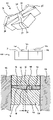
- FIG. 14 which is a side view of a cross section of a linking element 10 being located between the mould 45 , the cutting member 30 and the blanking member 110 which in this example functions as supporting member, a curved transition surface 111 being formed as a result of the retraction extends partially in the front surface 11 of the linking element 10 .
- a tilting line which would be formed in the transition surface 111 near the carrying surfaces 16 . would at the area of the carrying surfaces 16 be located lower, i.e. more in the direction of the back surface 12 of the linking element 10 , than at the area of the thicker central portion 23 being located at the area of the neck portion 14 in the horizontal transverse direction.
- the tilting line 18 is formed just outside the transition surface 111 , then the linking element 10 has a substantially constant thickness along the entire length of the tilting line 18 .
- a linking element 10 which is formed when the blanking member 110 is applied, is characterized by the fact that the tilting line 18 and the curved transition surface 111 are located at some distance A from each other. It goes for distance A that this is preferably as small as possible.
- FIGS. 10–13 show a fourth preferred embodiment of a blanking member according to the invention, which is indicated in general by the reference sign 100 .
- the blanking member comprises a portion 101 which is elevated with respect to the shaping surface 71 .
- the elevated portion 101 is centrally located in the horizontal direction, and extends along the entire height of the blanking member 100 .
- the elevated portion 101 extends along the entire neck portion 73 .
- the dimensions in the horizontal direction of the elevated portion 101 are at the area of the neck portion 73 smaller than these dimensions at the area of the basic portion 72 and the top portion 74 .
- the elevated portion 101 there are many possibilities for the shape of the elevated portion 101 at the shaping surface 71 .
- the elevated portion 101 can for example exclusively correspond to a portion of the tilting line 18 and the neck portion 14 of the linking element 10 being centrally located in the horizontal transverse direction. It is important that the elevated portion 101 is located substantially centrally in the horizontal direction.
- a main body surface 11 , 12 of the linking element 10 is pressed against the shaping surface 71 .
- material of the main body surface 11 , 12 is displaced.
- a linking element 10 is obtained, wherein the central portion 23 in any case is not elevated.
- FIGS. 11–13 show different possibilities for the shape in the horizontal direction of the elevated portion 101 .
- the angles between an edge 102 being raised in the longitudinal direction and a front surface 103 of the elevated portion 101 are indicated by the reference numeral 104 .
- the angles 104 may be substantially perpendicular, as shown in FIG. 11 , but may also be round, as shown in FIG. 12 .
- Another possibility is that no raised edge, a front surface and intermediate angles are present, but that the elevated portion 101 is substantially curved in its entirety in the horizontal direction, as shown in FIG. 13 .
- the elevated portion 101 may also be executed in an entirely or partially curved manner.
- the invention also relates to a blanking member which is provided with both two recessed portions 76 and an elevated neck portion 73 .
- final processing of the linking elements 10 is not at all excluded, wherein possible final processing can also be aimed at (further) reducing the variation in thickness in the horizontal transverse direction of the linking element 10 .
- both main body surfaces 11 , 12 of a linking element 10 while applying two blanking members according to the invention, wherein one of the two blanking members functions as cutting member and the other of the two blanking members functions as supporting member.
Landscapes
- Engineering & Computer Science (AREA)
- Mechanical Engineering (AREA)
- General Engineering & Computer Science (AREA)
- Transmissions By Endless Flexible Members (AREA)
- Punching Or Piercing (AREA)
- Automotive Seat Belt Assembly (AREA)
- Devices For Conveying Motion By Means Of Endless Flexible Members (AREA)
Applications Claiming Priority (3)
| Application Number | Priority Date | Filing Date | Title |
|---|---|---|---|
| NL1019639 | 2001-12-21 | ||
| NL1019639A NL1019639C2 (nl) | 2001-12-21 | 2001-12-21 | Werkwijze voor het vormen van een schakel voor een duwband voor een continu variabele transmissie. |
| PCT/NL2002/000839 WO2003072978A1 (en) | 2001-12-21 | 2002-12-17 | Process for forming a linking element for a push belt for a continuously variable transmission |
Related Parent Applications (1)
| Application Number | Title | Priority Date | Filing Date |
|---|---|---|---|
| PCT/NL2002/000839 Continuation WO2003072978A1 (en) | 2001-12-21 | 2002-12-17 | Process for forming a linking element for a push belt for a continuously variable transmission |
Publications (2)
| Publication Number | Publication Date |
|---|---|
| US20040221569A1 US20040221569A1 (en) | 2004-11-11 |
| US7076986B2 true US7076986B2 (en) | 2006-07-18 |
Family
ID=27607194
Family Applications (1)
| Application Number | Title | Priority Date | Filing Date |
|---|---|---|---|
| US10/867,454 Expired - Lifetime US7076986B2 (en) | 2001-12-21 | 2004-06-14 | Process for forming a linking element for a push belt for a continuously variable transmission |
Country Status (7)
| Country | Link |
|---|---|
| US (1) | US7076986B2 (ja) |
| EP (2) | EP1458992B1 (ja) |
| JP (1) | JP4440649B2 (ja) |
| AT (2) | ATE548139T1 (ja) |
| DE (1) | DE60209789T2 (ja) |
| NL (1) | NL1019639C2 (ja) |
| WO (1) | WO2003072978A1 (ja) |
Cited By (2)
| Publication number | Priority date | Publication date | Assignee | Title |
|---|---|---|---|---|
| US20070157696A1 (en) * | 2003-12-05 | 2007-07-12 | Prinsen Lucas Henricus R M | Fine-blanking device |
| US11506256B2 (en) * | 2018-04-03 | 2022-11-22 | Honda Motor Co., Ltd. | Metal element for continuously variable transmission and method of manufacture the same |
Families Citing this family (9)
| Publication number | Priority date | Publication date | Assignee | Title |
|---|---|---|---|---|
| NL1024530C2 (nl) * | 2003-10-14 | 2005-04-15 | Bosch Gmbh Robert | Het voorkomen van braamvorming bij een stansproces van een dwarselement voor een duwband voor een continu variabele transmissie. |
| NL1025080C2 (nl) * | 2003-12-19 | 2005-06-21 | Bosch Gmbh Robert | Gedeelde matrijs met ten minste twee matrijscomponenten. |
| NL1030702C2 (nl) * | 2005-12-19 | 2007-06-20 | Bosch Gmbh Robert | Werkwijze voor het vervaardigen van een dwarselement dat bestemd is om deel uit te maken van een duwband voor een continu variabele transmissie. |
| NL1032701C2 (nl) * | 2006-10-18 | 2008-04-22 | Bosch Gmbh Robert | Gedeeld stansorgaan dat bestemd is om te worden toegepast ten behoeve van het stansen van dwarselementen voor gebruik in een duwband voor een continu variabele transmissie. |
| NL1033140C2 (nl) * | 2006-12-27 | 2008-06-30 | Bosch Gmbh Robert | Drijfriem voor een continu variabele transmissie met dwarselementen voorzien van conctactgebieden. |
| JP2010029918A (ja) * | 2008-07-30 | 2010-02-12 | Aisin Aw Co Ltd | Cvtベルト用エレメントの打抜き加工方法及び打抜き加工用金型 |
| CN113260469A (zh) | 2018-12-24 | 2021-08-13 | 罗伯特·博世有限公司 | 精密冲裁工艺 |
| DE102019114950B4 (de) * | 2019-06-04 | 2021-04-29 | Schaeffler Technologies AG & Co. KG | Stanzteil zur Weiterverarbeitung zu einer Lasche für eine Laschenkette |
| NL1043501B1 (en) * | 2019-12-10 | 2021-08-31 | Bosch Gmbh Robert | A transverse segment for a drive belt and a drive belt for a continuously variable transmission including the transverse segment and a ring stack |
Citations (9)
| Publication number | Priority date | Publication date | Assignee | Title |
|---|---|---|---|---|
| US4320647A (en) * | 1979-02-22 | 1982-03-23 | Volvo Car B.V. | Method of and apparatus for making elements with profiled cross-section from sheet metal |
| US4826473A (en) * | 1986-10-30 | 1989-05-02 | Fuji Jukogyo Kabushiki Kaisha | Belt for a continuously variable transmission |
| US4894049A (en) * | 1987-01-23 | 1990-01-16 | Van Doorne's Transmissie B.V. | Transmission belt, cross element for a transmission belt and method and device for the production thereof |
| US6427512B2 (en) * | 2000-02-21 | 2002-08-06 | Honda Giken Kogyo Kabushiki Kaisha | Method of and apparatus for blanking elements of belt for continuously variable transmission |
| US6453716B2 (en) * | 2000-03-06 | 2002-09-24 | Honda Giken Kogyo Kabushiki Kaisha | Method of blanking elements of belt for continuously variable transmission |
| US6526798B2 (en) * | 2000-05-26 | 2003-03-04 | Honda Giken Kogyo Kabushiki Kaisha | Method of blanking element for belt for continuously variable transmission |
| US6742373B2 (en) * | 2000-04-17 | 2004-06-01 | Honda Giken Kogyo Kabushiki Kaisha | Method for manufacturing a V-block of a metal belt type continuously variable transmission |
| US6904782B2 (en) * | 2000-05-26 | 2005-06-14 | Honda Giken Kogyo Kabushiki Kaisha | Method of blanking an element for belt for continuously variable transmission |
| US6951124B2 (en) * | 2002-06-12 | 2005-10-04 | Aida Engineering Co., Ltd. | Method for making elements of a continuously variable transmission belt |
-
2001
- 2001-12-21 NL NL1019639A patent/NL1019639C2/nl not_active IP Right Cessation
-
2002
- 2002-12-17 JP JP2003571630A patent/JP4440649B2/ja not_active Expired - Lifetime
- 2002-12-17 EP EP20020789017 patent/EP1458992B1/en not_active Expired - Lifetime
- 2002-12-17 AT AT05077925T patent/ATE548139T1/de active
- 2002-12-17 WO PCT/NL2002/000839 patent/WO2003072978A1/en active IP Right Grant
- 2002-12-17 AT AT02789017T patent/ATE319949T1/de not_active IP Right Cessation
- 2002-12-17 EP EP20050077925 patent/EP1637248B1/en not_active Expired - Lifetime
- 2002-12-17 DE DE2002609789 patent/DE60209789T2/de not_active Expired - Lifetime
-
2004
- 2004-06-14 US US10/867,454 patent/US7076986B2/en not_active Expired - Lifetime
Patent Citations (9)
| Publication number | Priority date | Publication date | Assignee | Title |
|---|---|---|---|---|
| US4320647A (en) * | 1979-02-22 | 1982-03-23 | Volvo Car B.V. | Method of and apparatus for making elements with profiled cross-section from sheet metal |
| US4826473A (en) * | 1986-10-30 | 1989-05-02 | Fuji Jukogyo Kabushiki Kaisha | Belt for a continuously variable transmission |
| US4894049A (en) * | 1987-01-23 | 1990-01-16 | Van Doorne's Transmissie B.V. | Transmission belt, cross element for a transmission belt and method and device for the production thereof |
| US6427512B2 (en) * | 2000-02-21 | 2002-08-06 | Honda Giken Kogyo Kabushiki Kaisha | Method of and apparatus for blanking elements of belt for continuously variable transmission |
| US6453716B2 (en) * | 2000-03-06 | 2002-09-24 | Honda Giken Kogyo Kabushiki Kaisha | Method of blanking elements of belt for continuously variable transmission |
| US6742373B2 (en) * | 2000-04-17 | 2004-06-01 | Honda Giken Kogyo Kabushiki Kaisha | Method for manufacturing a V-block of a metal belt type continuously variable transmission |
| US6526798B2 (en) * | 2000-05-26 | 2003-03-04 | Honda Giken Kogyo Kabushiki Kaisha | Method of blanking element for belt for continuously variable transmission |
| US6904782B2 (en) * | 2000-05-26 | 2005-06-14 | Honda Giken Kogyo Kabushiki Kaisha | Method of blanking an element for belt for continuously variable transmission |
| US6951124B2 (en) * | 2002-06-12 | 2005-10-04 | Aida Engineering Co., Ltd. | Method for making elements of a continuously variable transmission belt |
Cited By (2)
| Publication number | Priority date | Publication date | Assignee | Title |
|---|---|---|---|---|
| US20070157696A1 (en) * | 2003-12-05 | 2007-07-12 | Prinsen Lucas Henricus R M | Fine-blanking device |
| US11506256B2 (en) * | 2018-04-03 | 2022-11-22 | Honda Motor Co., Ltd. | Metal element for continuously variable transmission and method of manufacture the same |
Also Published As
| Publication number | Publication date |
|---|---|
| JP4440649B2 (ja) | 2010-03-24 |
| EP1637248A3 (en) | 2010-05-26 |
| EP1458992A1 (en) | 2004-09-22 |
| JP2005518513A (ja) | 2005-06-23 |
| ATE548139T1 (de) | 2012-03-15 |
| ATE319949T1 (de) | 2006-03-15 |
| EP1637248A2 (en) | 2006-03-22 |
| EP1458992B1 (en) | 2006-03-08 |
| EP1637248B1 (en) | 2012-03-07 |
| WO2003072978A1 (en) | 2003-09-04 |
| NL1019639C2 (nl) | 2003-06-24 |
| DE60209789D1 (de) | 2006-05-04 |
| DE60209789T2 (de) | 2006-11-09 |
| US20040221569A1 (en) | 2004-11-11 |
Similar Documents
| Publication | Publication Date | Title |
|---|---|---|
| US7076986B2 (en) | Process for forming a linking element for a push belt for a continuously variable transmission | |
| US8100797B2 (en) | Method for forming a tilting zone on a transverse element for a push belt for a continuously variable transmission | |
| US20190346016A1 (en) | A transverse segment for a drive belt for a continuously variable transmission | |
| KR20010067423A (ko) | 연속 가변 변속기용 구동 벨트, 그 연속 밴드 및 연속밴드 제조 방법 | |
| US7806794B2 (en) | Power transmission chain and power transmission device | |
| EP1267091A2 (en) | Transverse element having a conical neck portion | |
| US20040072644A1 (en) | Transverse element for a drive belt for a continuously variable transmission | |
| EP1424508B1 (en) | Metal driving belt | |
| KR100796428B1 (ko) | 구동 벨트 | |
| EP1369619A2 (en) | Belt | |
| EP1899622B1 (en) | Push belt with curved transverse elements | |
| CN100451381C (zh) | 传动带 | |
| NL1030811C1 (nl) | Drijfriem en dwarselement voor een drijfriem. | |
| KR102230400B1 (ko) | 캐리어 링을 갖는 구동 벨트용 횡단 세그먼트 및 다중 횡단 세그먼트 | |
| US9308575B2 (en) | Power transmission chain pin and manufacture method thereof | |
| EP1699579B1 (en) | Divided mould having at least two mould components | |
| JP4847468B2 (ja) | 無段変速機用プッシュベルトの横断要素形成方法および前記横断要素の打ち抜き形成用型 | |
| JP6129205B2 (ja) | 連続可変トランスミッションの駆動ベルトに使用される横断エレメントを打ち抜くための分割型ブランキング部材 | |
| WO2013100759A1 (en) | Method for forming a tilting zone on a transverse element for a push belt for a continuously variable transmission |
Legal Events
| Date | Code | Title | Description |
|---|---|---|---|
| AS | Assignment |
Owner name: VAN DOORNE'S TRANSMISSIE B.V., NETHERLANDS Free format text: ASSIGNMENT OF ASSIGNORS INTEREST;ASSIGNORS:MUTSAERS, ROBERT ARNOLDUS ANDREAS;BUYSEN, LAMBERTUS CORNELIS HENDRIKUS;VAN LIEMPD, JEROEN HERMAN;AND OTHERS;REEL/FRAME:015475/0558 Effective date: 20040603 |
|
| FEPP | Fee payment procedure |
Free format text: PAYOR NUMBER ASSIGNED (ORIGINAL EVENT CODE: ASPN); ENTITY STATUS OF PATENT OWNER: LARGE ENTITY |
|
| STCF | Information on status: patent grant |
Free format text: PATENTED CASE |
|
| FEPP | Fee payment procedure |
Free format text: PAYER NUMBER DE-ASSIGNED (ORIGINAL EVENT CODE: RMPN); ENTITY STATUS OF PATENT OWNER: LARGE ENTITY Free format text: PAYOR NUMBER ASSIGNED (ORIGINAL EVENT CODE: ASPN); ENTITY STATUS OF PATENT OWNER: LARGE ENTITY |
|
| FPAY | Fee payment |
Year of fee payment: 4 |
|
| FPAY | Fee payment |
Year of fee payment: 8 |
|
| MAFP | Maintenance fee payment |
Free format text: PAYMENT OF MAINTENANCE FEE, 12TH YEAR, LARGE ENTITY (ORIGINAL EVENT CODE: M1553) Year of fee payment: 12 |