US7073644B2 - Anti-vibration system for use in exposure apparatus - Google Patents
Anti-vibration system for use in exposure apparatus Download PDFInfo
- Publication number
- US7073644B2 US7073644B2 US10/329,828 US32982802A US7073644B2 US 7073644 B2 US7073644 B2 US 7073644B2 US 32982802 A US32982802 A US 32982802A US 7073644 B2 US7073644 B2 US 7073644B2
- Authority
- US
- United States
- Prior art keywords
- pressure
- control valve
- denoted
- pressure control
- supply
- Prior art date
- Legal status (The legal status is an assumption and is not a legal conclusion. Google has not performed a legal analysis and makes no representation as to the accuracy of the status listed.)
- Expired - Fee Related, expires
Links
Images


Classifications
-
- F—MECHANICAL ENGINEERING; LIGHTING; HEATING; WEAPONS; BLASTING
- F16—ENGINEERING ELEMENTS AND UNITS; GENERAL MEASURES FOR PRODUCING AND MAINTAINING EFFECTIVE FUNCTIONING OF MACHINES OR INSTALLATIONS; THERMAL INSULATION IN GENERAL
- F16F—SPRINGS; SHOCK-ABSORBERS; MEANS FOR DAMPING VIBRATION
- F16F15/00—Suppression of vibrations in systems; Means or arrangements for avoiding or reducing out-of-balance forces, e.g. due to motion
- F16F15/02—Suppression of vibrations of non-rotating, e.g. reciprocating systems; Suppression of vibrations of rotating systems by use of members not moving with the rotating systems
- F16F15/023—Suppression of vibrations of non-rotating, e.g. reciprocating systems; Suppression of vibrations of rotating systems by use of members not moving with the rotating systems using fluid means
- F16F15/027—Suppression of vibrations of non-rotating, e.g. reciprocating systems; Suppression of vibrations of rotating systems by use of members not moving with the rotating systems using fluid means comprising control arrangements
- F16F15/0275—Control of stiffness
Definitions
- This invention relates generally to an anti-vibration system for use in a semiconductor manufacturing apparatus and, specifically, having an air spring as an actuator.
- the invention concerns an anti-vibration method, an anti-vibration system control method, and an exposure apparatus having such an anti-vibration system.
- semiconductor manufacturing apparatuses need an anti-vibration system capable of isolating external vibration such as floor vibration as much as possible, so as to assure appropriate and quick exposure operations.
- a stepper an exposure X-Y stage positioned with respect to a projection lens must be placed in a completely stopped state.
- the exposure X-Y stage is featured by the intermittent motion of a step-and-repeat operation, the repeated stepwise motion excites vibration of an anti-vibration table.
- an anti-vibration performance in relation to external vibration as well as a damping performance with respect to vibration caused by the operation of an instrument itself mounted thereon should be accomplished in well balance.
- anti-vibration systems of what can be called active type have been developed practically, in which vibration of an anti-vibration table is detected by a vibration sensor and the anti-vibration table is driven by an actuator in response to a detection signal of the sensor.
- Such active type anti-vibration systems can achieve balanced anti-vibration performance and damping performance, which are not attainable with conventional anti-vibration systems which comprise a spring and a supporting mechanism having a damper characteristic.
- the active type anti-vibration system usually has an air spring as an actuator. Because of its structure, the air spring can produce a large thrust easily, so it can stably support a heavy weight such as a main unit of a semiconductor manufacturing apparatus.
- the natural vibration frequency of the supporting system thereof can be set at a low frequency such as a few Hz, such that a sufficient anti-vibration performance is assured with respect to external vibration having a high vibration frequency.
- the air spring produces a thrust in accordance with the internal pressure thereof.
- the internal pressure is controlled by a pressure control valve, having pressure controllability.
- the pressure control valve has a pressure controllable range, ranging from the supply pressure of a supplied high pressure air to the exhaust pressure being open to the atmosphere. It operates to adjust a target pressure, in accordance with an input signal applied thereto. Namely, the problem of this pressure control valve, producing an output pressure, is that the output pressure of the pressure control valve is variable due to the influence of a change in the supply pressure.
- the high pressure air is supplied to the pressure control valve via a supply pressure stabilizing means such as a pressure reducing valve. Since, however, the flow rate of the high pressure air flowing through the pressure control valve changes due to the operation of the pressure control valve, the supply pressure changes with the flow rate.
- the pressure control valve is actuated in response to a detection signal of a vibration sensor.
- the anti-vibration system has a natural vibration frequency of about a few Hz
- the detection signal of the vibration sensor mainly comprises a frequency component not less than a few Hz.
- the pressure control valve operates in such a frequency band
- the response speed of the supply pressure stabilizing means such as a pressure reducing valve is significantly lower than the natural vibration frequency of the anti-vibration system. While the supply pressure stabilizing means operates so as to maintain the supply pressure constant, it is impossible to assure the response performance that can follow the changes in the flow rate of the pressure control valve which operates at a high speed.
- the supply pressure is reduced to a target pressure by use of a throttle mechanism, to provide an output pressure.
- the output pressure is influenced thereby and also decreases.
- the output pressure increases similarly.
- FIG. 1 is a schematic and diagrammatic view of an anti-vibration system according to one preferred embodiment of the present invention.
- FIG. 2 is a diagrammatic view for explaining a control system having a variable gain compensation means, according to an embodiment of the present invention.
- FIG. 3 is a diagrammatic view for explaining a control system having an offset adding means, according to an embodiment of the present invention.
- FIG. 4 is a diagrammatic view for explaining a pressure control valve, in one form of a pressure control valve according to an embodiment of the present invention, as well as disposition of pressure sensors.
- FIG. 5 is a diagrammatic view for explaining the structure of a pressure control valve according to an embodiment of the present invention.
- FIG. 6 is a graph for explaining an output characteristic of a pressure control valve according to an embodiment of the present invention.
- FIG. 7 is a graph for explaining a flow rate characteristic of a pressure control valve according to an embodiment of the present invention.
- FIG. 8 is a graph for explaining a supply pressure to a pressure control valve according to an embodiment of the present invention, as well as the gain of the pressure control valve.
- FIG. 9 is a graph for explaining an offset of the input signal and the supply pressure, in an embodiment of the present invention.
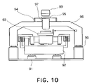
- FIG. 10 is a schematic and elevational view of an embodiment of an exposure apparatus, into which an anti-vibration system according to the present invention is incorporated.
- FIG. 1 illustrates the structure of an anti-vibration system according to an embodiment of the present invention.
- An anti-vibration table 1 is floatingly supported on the floor, by means of an air spring 2 .
- the internal pressure of the air spring 2 is controlled by a pressure control valve 3 , which is a pressure control valve having pressure controllability.
- the air spring 2 (actuator) applies a damping force to the anti-vibration table 1 , thereby to control the vibration damping and the floated position of the anti-vibration table 1 .
- vibration of the anti-vibration table 1 is detected by a vibration sensor, and the pressure control valve 3 is actuated in response to a detection signal of the vibration sensor, by which the vibration of the anti-vibration table 1 is suppressed.
- a vibration sensor to this end, there is an acceleration sensor 5 which is provided on the anti-vibration table 1 .
- the acceleration sensor 5 can detect vibration of the anti-vibration table 1 .
- a displacement sensor 6 which functions to detect the floated position of the anti-vibration table 1 .
- the pressure control valve 3 In response to a detection signal of the displacement sensor 6 , the pressure control valve 3 is actuated.
- a pressure sensor 4 detects the supply pressure of the pressure control valve 3 .
- the supply pressure refers to the pressure of a high pressure air to be supplied to the pressure control valve 3 through a pressure stabilizing mechanism such as a pressure reducing valve.
- the pressure control valve 3 comprises a three-port valve having an intake port I, an exhaust port E, and an output port O.
- the pressure control valve 3 receives the supply of a high pressure air at its intake port I.
- the supply pressure at the intake port I is detected by the pressure sensor 4 .
- the exhaust port E is normally open to the atmosphere.
- the output port O is connected to the air spring 2 , and the output pressure of the pressure control valve 3 is the same as the inside pressure of the air spring 2 .
- the passage resistance of each of the throttle mechanisms 11 and 12 is variable.
- Typical mechanisms are nozzle flapper type, pivot type and so on. In the case of nozzle flapper type, flappers are actuated such that the passage resistances of the throttle mechanisms 11 and 12 are made variable.
- the high pressure air (working fluid) is exhausted constantly from the intake port I to the exhaust port E.
- FIG. 6 shows the input-output characteristic of the pressure control valve 3 .
- Symbol P so at the axis of ordinate denotes the supply pressure
- the pressure control valve 3 produces an output pressure from zero to P so in response to an input signal.
- the input signal and the output pressure are approximately proportional to each other.
- FIG. 7 is a graph for explaining the relation between the flow rate of the high pressure air (working fluid) and the input signal. Since the passage resistances of the throttle mechanisms 11 and 12 of the pressure control valve 3 are variable, the passage resistance to the flow of the high pressure air changes in accordance with the operation of the pressure control valve 3 . Thus, the flow rate changes with the input signal, in the manner as shown in FIG. 7 .
- the high pressure air is supplied to the pressure control valve 3 by way of a supply pressure stabilizing means such as a pressure reducing valve.
- the pressure stabilizing means operates to maintain the supply pressure constant, regardless of the flow rate. If the operation of the air valve 3 is in a steady state, the supply pressure is constant. However, the pressure stabilizing means such as a pressure reducing valve has a slow response as compared with the pressure control valve 3 . Therefore, from the structural reason, it is impossible to assure sufficient response characteristic.
- the pressure control valve 3 operates at a high speed, with the feedback of a detection signal of the acceleration sensor 5 . Thus, the flow rate changes quickly in response to the operation of the pressure control valve. Therefore, correction of the supply pressure by the supply pressure stabilizing means can not follow it, and the supply pressure changes transitionally.
- the pressure control valve 3 produces an output pressure, while reducing the supply pressure by use of the throttle mechanism 11 . Therefore, if the supply pressure changes, also the output pressure changes in proportion to it. If the supply pressure increases, the output pressure raises in proportion to it. To the contrary, if the supply pressure decreases, the output pressure decreases similarly. In order to assure that the pressure control valve 3 produces a desired output pressure in response to an input signal, appropriate compensation is provided so as to avoid the influence of the supply pressure change.
- the pressure sensor 4 detects the supply pressure, and the pressure control valve 3 is actuated in accordance with the detection signal of the sensor 4 .
- the anti-vibration system of this embodiment has a feature that, in accordance with the supply pressure, variable gain compensation is performed to the input signal to be applied to driving means 7 , for actuating the air valve 3 .
- FIG. 2 shows the structure of a control system for the pressure control valve 3 , having variable gain compensation means 8 .
- P so is the supply pressure in equilibrium
- P s is the supply pressure detected in real time by the pressure sensor 4 .
- Denoted at i is the input signal to be applied to the driving circuit 7 of the pressure control valve 3
- denoted at i 0 is the input signal under an assumption that the supply pressure P so is unchanged.
- the driving circuit 7 is a power amplifier for driving the pressure control valve 3 in accordance with the input signal i.
- the variable gain compensation means 8 operates to avoid the influence of the change in supply pressure to the output pressure of the pressure control valve 3 .
- the operation principle of the variable gain compensation means 8 will be explained.
- the valve 3 under equilibrium condition, the valve 3 produces an output pressure ranging from zero to supply pressure P so , approximately in proportion to the input signal i. If the supply pressure reduces to P s transitionally due to the operation of the pressure control valve 3 , the output pressure which can be produced is restricted to a range from zero to P s . Thus, the gain of the output pressure to the input signal is lowered from P so to P s . In order to keep the gain in equilibrium of P so even if the supply pressure decreases to P s , the supply pressure ratio P so /P s is multiplied to the input signal to thereby compensate for such decrease of the gain.
- the pressure control valve 3 is actuated in accordance with a detection signal of the displacement sensor 6 or of the acceleration sensor 5 , to thereby control the vibration damping and floated position of the anti-vibration table 1 .
- the input signal i 0 is produced while applying appropriate compensation to the detection signal of the displacement sensor 6 or acceleration sensor 5 .
- the internal pressure of the air spring 2 (actuator) is controlled by the pressure control valve 3 . Therefore, if the gain for the output pressure changes with the state of the supply pressure, it is unable to control the vibration damping and the floated position suitably.
- the variable gain compensation means 8 carries out the calculation of equation (1) below, to the input signal i 0 , whereby the input signal i to the driving circuit 7 is produced.
- i ( P so /P s ) ⁇ i 0 (1)
- the gain of the output pressure to the input signal i 0 can be held constant, regardless of the supply pressure.
- the internal pressure of the air spring 2 can be controlled suitably without being influenced by a change in supply pressure of the pressure control valve 3 .
- An anti-vibration system is arranged so that the supply pressure is detected by a pressure sensor 4 and the pressure control valve 3 is actuated in response to a detection signal of the sensor, wherein, in accordance with the supply pressure, an offset signal is added to the input signal of driving means 7 which actuates the pressure control valve 3 .
- FIG. 3 shows the structure of a control system for the pressure control valve 3 , using offset adding means 9 .
- the offset adding means 9 produces an offset signal ⁇ i so as to compensate for the influence of a change in the supply pressure to the output pressure.
- the operation principle of the offset adding means 9 will be explained.
- the output pressure to an input signal i 0 where the supply pressure P so is unchanged is denoted by P 0 .
- the offset signal to be added to the input signal is denoted by ⁇ i.
- the offset signal ⁇ i is determined, as shown in equation (2) below, by the supply pressures P so and P s and the input signal i 0 .
- ⁇ i ( P so /P s ⁇ 1) ⁇ i 0 (2)
- the offset adding means 9 produces an offset signal ⁇ i in accordance with the operation of equation (2).
- the offset signal ⁇ i is added to the input signal i 0 to the driving means 7 as shown in equation (3), the output pressure can be continuously held constant regardless of the supply pressure. Therefore, the internal pressure of the air spring 2 can be controlled suitably, without being influenced by changes in the supply pressure of the pressure control valve 3 .
- the anti-vibration table is supported by use of plural air springs.
- three or more air springs 2 are used and they are disposed approximately symmetrically with respect to the gravity center position of the anti-vibration table 1 .
- the anti-vibration system of this embodiment has a feature that pressure sensors for detecting the supply pressure are provided at respective intake passageways each being adapted to supply an air only to an associated pressure control valve.
- FIG. 4 shows an example wherein an anti-vibration table 1 is supported by four air springs 2 a, 2 b, 2 c, and 2 d.
- the anti-vibration table 1 is supported at four corners thereof by means of the four air springs 2 a – 2 d.
- the inside pressures of the air springs 2 a – 2 d are controlled by pressure control valves 3 a, 3 b, 3 c, and 3 d, respectively.
- the intake passageway 15 is branched in the neighborhood of the air springs 2 a – 2 d, so that high pressure airs can be supplied to the pressure control valves 3 a – 3 d, respectively.
- an exhaust passageway 16 combines exhaust gases from the pressure control valves 3 a – 3 d and directs them to a single exhaust port, concentratedly.
- pressure sensors 4 a, 4 b, 4 c, and 4 d are disposed on air supply passageways 15 , respectively, each being branched from the intake port so as to supply an air only to an associated one of the pressure control valves 3 a – 3 d. Where the driving operations of the pressure control valves 3 a – 3 d are different, changes in the supply pressures of them are different, in dependence upon the branch of the air supply passageways 15 .
- the output pressure characteristic of the pressure control valve is determined by the supply pressure of the air supply passageway in close proximity to the pressure control valve. Therefore, in order to avoid the influence of the supply pressure change from the output pressure at the air valves 3 a – 3 d, the pressure sensors 4 a – 4 d for detecting the supply pressure should be disposed at positions on the air supply passageways which are very close to the air valves 3 a – 3 d, respectively.
- the pressure sensors 4 a – 4 d are provided on passageways each being branched from the intake port and being adapted to supply an air only to an associated one of the pressure control valves 3 a – 3 d.
- the pressure control valve 3 a is actuated in response to a detection signal of the supply pressure, detected by the pressure sensor 4 a.
- compensation means for avoiding the influence of the supply pressure change from the output pressure of the pressure control valve 3 a any one of the compensation means shown in FIGS. 2 and 3 may be used.
- the pressure control valves 3 b, 3 c, and 3 d operate in response to detection signals of the pressure sensors 4 b, 4 c, and 4 d, respectively.
- the internal pressures of the air springs 2 a – 2 d can be controlled appropriately, while avoiding the influence of the change in the supply pressure.
- FIG. 4 shows an anti-vibration system having four air springs 2 a – 2 d for supporting the anti-vibration table 1
- the present invention can be embodied appropriately regardless of the number of air springs used.
- a semiconductor manufacturing apparatus having an anti-vibration system according to the present invention can be embodied appropriately, for various types of semiconductor manufacturing apparatuses, regardless of a used exposure method such as sequential exposure method or scanning exposure method.
- This exposure apparatus comprise at least one of a reticle stage and a wafer sage, as a stage mechanism having an anti-vibration system according to any one of the embodiments described hereinbefore.
- a barrel base 96 is supported by a floor or a base table 91 , through dampers 98 .
- the barrel base 96 functions to support a reticle stage base 94 as well as a projection optical system 97 which is positioned between a reticle stage 95 and a wafer stage 93 .
- the wafer stage 93 is supported on a stage base 92 which is supported by the floor or the base table 91 .
- the wafer stage 93 serves to carry a wafer thereon and to perform positioning of the same.
- the reticle stage 95 is supported by the reticle stage base 94 which is supported by the barrel base 96 .
- the reticle stage 95 is movable and it serves to carry thereon a reticle having a circuit pattern formed thereon. Exposure light for exposing the wafer on the wafer stage 93 with the reticle mounted on the reticle stage 95 , is produced by an illumination optical system 99 .
- the wafer stage 93 is scanned in synchronism with the reticle stage 95 .
- the positions of these stages are continuously detected by interferometers, respectively, and the detected positions are fed back to driving units for the reticle stage 95 and the wafer stage 93 .
- the scan start positions of them can be synchronized with each other exactly and, additionally, the scan speed in a constant-speed scan region can be controlled very precisely.
- the reticle pattern is exposed to the wafer, whereby the circuit pattern is transferred to the latter.
- This embodiment uses at least one of a reticle stage and a wafer stage, as a stage mechanism having an anti-vibration system according to any one of the embodiments described hereinbefore. Therefore, even if the supply pressure to the pressure control valve changes, an unwanted change of the output pressure of the pressure control valve due to the influence of the supply pressure change can be prevented. As a result, the internal pressure of the air spring can be controlled appropriately, and vibration damping can be controlled stably. Thus, a high speed and high precision exposure apparatus operation is assured.
Abstract
In order to control an internal pressure of an air spring appropriately without being influenced by a change in supply pressure, an anti-vibration system includes an air spring as an actuator for an anti-vibration table, a pressure control valve for controlling the internal pressure of the air spring, a pressure sensor for detecting the air supply pressure to the pressure control valve, a driving system for actuating the pressure control valve in accordance with a detection signal of the pressure sensor, and a variable gain compensation system for performing variable gain compensation to an input signal to the driving system for the pressure control valve, on the basis of the detection signal of the pressure sensor.
Description
This invention relates generally to an anti-vibration system for use in a semiconductor manufacturing apparatus and, specifically, having an air spring as an actuator. In other aspects, the invention concerns an anti-vibration method, an anti-vibration system control method, and an exposure apparatus having such an anti-vibration system.
Improvements in the precision of precision instruments such as electronic microscopes and semiconductor manufacturing apparatuses, for example, have required further improvements in performance of a precision anti-vibration system on which such a precision instrument is to be mounted. Particularly, semiconductor manufacturing apparatuses need an anti-vibration system capable of isolating external vibration such as floor vibration as much as possible, so as to assure appropriate and quick exposure operations. The reason is that, where a semiconductor wafer is to be exposed by use of what is called a stepper, an exposure X-Y stage positioned with respect to a projection lens must be placed in a completely stopped state.
Further, since the exposure X-Y stage is featured by the intermittent motion of a step-and-repeat operation, the repeated stepwise motion excites vibration of an anti-vibration table.
For these reasons, in the anti-vibration systems, an anti-vibration performance in relation to external vibration as well as a damping performance with respect to vibration caused by the operation of an instrument itself mounted thereon should be accomplished in well balance.
In order to meet this, anti-vibration systems of what can be called active type have been developed practically, in which vibration of an anti-vibration table is detected by a vibration sensor and the anti-vibration table is driven by an actuator in response to a detection signal of the sensor. Such active type anti-vibration systems can achieve balanced anti-vibration performance and damping performance, which are not attainable with conventional anti-vibration systems which comprise a spring and a supporting mechanism having a damper characteristic. The active type anti-vibration system usually has an air spring as an actuator. Because of its structure, the air spring can produce a large thrust easily, so it can stably support a heavy weight such as a main unit of a semiconductor manufacturing apparatus. Further, due to the use of an air spring in an anti-vibration system, the natural vibration frequency of the supporting system thereof can be set at a low frequency such as a few Hz, such that a sufficient anti-vibration performance is assured with respect to external vibration having a high vibration frequency.
The air spring produces a thrust in accordance with the internal pressure thereof. The internal pressure is controlled by a pressure control valve, having pressure controllability. The pressure control valve has a pressure controllable range, ranging from the supply pressure of a supplied high pressure air to the exhaust pressure being open to the atmosphere. It operates to adjust a target pressure, in accordance with an input signal applied thereto. Namely, the problem of this pressure control valve, producing an output pressure, is that the output pressure of the pressure control valve is variable due to the influence of a change in the supply pressure.
The high pressure air is supplied to the pressure control valve via a supply pressure stabilizing means such as a pressure reducing valve. Since, however, the flow rate of the high pressure air flowing through the pressure control valve changes due to the operation of the pressure control valve, the supply pressure changes with the flow rate.
The pressure control valve is actuated in response to a detection signal of a vibration sensor. Here, usually, the anti-vibration system has a natural vibration frequency of about a few Hz, and the detection signal of the vibration sensor mainly comprises a frequency component not less than a few Hz. Although the pressure control valve operates in such a frequency band, the response speed of the supply pressure stabilizing means such as a pressure reducing valve is significantly lower than the natural vibration frequency of the anti-vibration system. While the supply pressure stabilizing means operates so as to maintain the supply pressure constant, it is impossible to assure the response performance that can follow the changes in the flow rate of the pressure control valve which operates at a high speed.
Inside the pressure control valve, the supply pressure is reduced to a target pressure by use of a throttle mechanism, to provide an output pressure. Thus, if the supply pressure decreases, the output pressure is influenced thereby and also decreases. Alternatively, if the supply pressure increases, the output pressure increases similarly. Thus, there is an inconvenience that, when the pressure control valve operates, the operation speed of the supply pressure stabilizing means which supplies a high pressure cannot follow it, such that the supply pressure changes and a desired output pressure cannot be produced in response to an input signal applied to the pressure control valve.
Further, depending on the setting environment in which the system is installed, it is possible that a change in supply pressure such as described above occurs. It has been desired to provide pressure control means that can stably hold a required anti-vibration performance even in such environment.
It is accordingly an object of the present invention to provide an anti-vibration system and/or an anti-vibration method by which the internal pressure of an air spring can be controlled suitably.
It is another object of the present invention to provide an exposure apparatus having such anti-vibration system.
These and other objects, features and advantages of the present invention will become more apparent upon a consideration of the following description of the preferred embodiments of the present invention taken in conjunction with the accompanying drawings.
Anti-vibration systems and methods according to preferred embodiments of the present invention will now be described with reference to the attached drawings.
In this anti-vibration system, vibration of the anti-vibration table 1 is detected by a vibration sensor, and the pressure control valve 3 is actuated in response to a detection signal of the vibration sensor, by which the vibration of the anti-vibration table 1 is suppressed. As a vibration sensor to this end, there is an acceleration sensor 5 which is provided on the anti-vibration table 1. The acceleration sensor 5 can detect vibration of the anti-vibration table 1. Also, in this anti-vibration system, in order to hold the floated position of the anti-vibration table 1 at a constant position, there is a displacement sensor 6 which functions to detect the floated position of the anti-vibration table 1. In response to a detection signal of the displacement sensor 6, the pressure control valve 3 is actuated. A pressure sensor 4 detects the supply pressure of the pressure control valve 3. Here, the supply pressure refers to the pressure of a high pressure air to be supplied to the pressure control valve 3 through a pressure stabilizing mechanism such as a pressure reducing valve.
Referring to FIG. 5 , the operation of the pressure control valve 3 will be explained. The pressure control valve 3 comprises a three-port valve having an intake port I, an exhaust port E, and an output port O. The pressure control valve 3 receives the supply of a high pressure air at its intake port I. The supply pressure at the intake port I is detected by the pressure sensor 4. The exhaust port E is normally open to the atmosphere. The output port O is connected to the air spring 2, and the output pressure of the pressure control valve 3 is the same as the inside pressure of the air spring 2. There are throttle mechanisms 11 and 12 between the intake port I and the output port O and between the output port O and the exhaust port E, respectively. In accordance with the ratio of passage resistances of these throttle mechanisms 11 and 12, the output pressure is determined. The passage resistance of each of the throttle mechanisms 11 and 12 is variable. Typical mechanisms are nozzle flapper type, pivot type and so on. In the case of nozzle flapper type, flappers are actuated such that the passage resistances of the throttle mechanisms 11 and 12 are made variable. The high pressure air (working fluid) is exhausted constantly from the intake port I to the exhaust port E.
The high pressure air is supplied to the pressure control valve 3 by way of a supply pressure stabilizing means such as a pressure reducing valve. The pressure stabilizing means operates to maintain the supply pressure constant, regardless of the flow rate. If the operation of the air valve 3 is in a steady state, the supply pressure is constant. However, the pressure stabilizing means such as a pressure reducing valve has a slow response as compared with the pressure control valve 3. Therefore, from the structural reason, it is impossible to assure sufficient response characteristic. In the anti-vibration system, the pressure control valve 3 operates at a high speed, with the feedback of a detection signal of the acceleration sensor 5. Thus, the flow rate changes quickly in response to the operation of the pressure control valve. Therefore, correction of the supply pressure by the supply pressure stabilizing means can not follow it, and the supply pressure changes transitionally.
As shown in FIG. 5 , the pressure control valve 3 produces an output pressure, while reducing the supply pressure by use of the throttle mechanism 11. Therefore, if the supply pressure changes, also the output pressure changes in proportion to it. If the supply pressure increases, the output pressure raises in proportion to it. To the contrary, if the supply pressure decreases, the output pressure decreases similarly. In order to assure that the pressure control valve 3 produces a desired output pressure in response to an input signal, appropriate compensation is provided so as to avoid the influence of the supply pressure change.
More specifically, in the anti-vibration system of this embodiment, the pressure sensor 4 detects the supply pressure, and the pressure control valve 3 is actuated in accordance with the detection signal of the sensor 4. Namely, the anti-vibration system of this embodiment has a feature that, in accordance with the supply pressure, variable gain compensation is performed to the input signal to be applied to driving means 7, for actuating the air valve 3.
Referring to the input signal vs. output pressure diagram of FIG. 8 , the operation principle of the variable gain compensation means 8 will be explained. As regards the output pressure of the pressure control valve 3, under equilibrium condition, the valve 3 produces an output pressure ranging from zero to supply pressure Pso, approximately in proportion to the input signal i. If the supply pressure reduces to Ps transitionally due to the operation of the pressure control valve 3, the output pressure which can be produced is restricted to a range from zero to Ps. Thus, the gain of the output pressure to the input signal is lowered from Pso to Ps. In order to keep the gain in equilibrium of Pso even if the supply pressure decreases to Ps, the supply pressure ratio Pso/Ps is multiplied to the input signal to thereby compensate for such decrease of the gain.
In the anti-vibration system according to this embodiment, the pressure control valve 3 is actuated in accordance with a detection signal of the displacement sensor 6 or of the acceleration sensor 5, to thereby control the vibration damping and floated position of the anti-vibration table 1. In FIG. 2 , the input signal i0 is produced while applying appropriate compensation to the detection signal of the displacement sensor 6 or acceleration sensor 5. The internal pressure of the air spring 2 (actuator) is controlled by the pressure control valve 3. Therefore, if the gain for the output pressure changes with the state of the supply pressure, it is unable to control the vibration damping and the floated position suitably. In accordance with the operation principle as has been explained with reference to FIG. 8 , the variable gain compensation means 8 carries out the calculation of equation (1) below, to the input signal i0, whereby the input signal i to the driving circuit 7 is produced.
i=(P so /P s)×i 0 (1)
i=(P so /P s)×i 0 (1)
With this procedure, the gain of the output pressure to the input signal i0 can be held constant, regardless of the supply pressure. As a result, the internal pressure of the air spring 2 can be controlled suitably without being influenced by a change in supply pressure of the pressure control valve 3.
Here, it is seen from equation (1) that, if Pso=Ps and the supply pressure is unchanged from the equilibrium, the gain of the variable gain compensation means 8 is equal to 1. Therefore, in this case, no compensation is performed to the input signal i0.
Another embodiment of the present invention will be described. An anti-vibration system according to this embodiment is arranged so that the supply pressure is detected by a pressure sensor 4 and the pressure control valve 3 is actuated in response to a detection signal of the sensor, wherein, in accordance with the supply pressure, an offset signal is added to the input signal of driving means 7 which actuates the pressure control valve 3.
Referring to the input signal vs. output pressure diagram of FIG. 9 , the operation principle of the offset adding means 9 will be explained. Here the output pressure to an input signal i0 where the supply pressure Pso is unchanged, is denoted by P0. Even if the supply pressure decreases to Ps, since the output pressure P0 is unchanged, the offset signal to be added to the input signal is denoted by Δi. The offset signal Δi is determined, as shown in equation (2) below, by the supply pressures Pso and Ps and the input signal i0.
Δi=(P so /P s−1)×i 0 (2)
Δi=(P so /P s−1)×i 0 (2)
By changing the input signal from i0 to i0+Δi as the supply pressure decreases from Pso to Ps, the output pressure P0 can be kept unchanged.
The offset adding means 9 produces an offset signal Δi in accordance with the operation of equation (2). As shown in equation (3) below, the input signal i to the driving means 7 corresponds to the sum of the input signal i0 and the offset signal Δi.
i=i 0 +Δi (3)
i=i 0 +Δi (3)
Since the offset signal Δi is added to the input signal i0 to the driving means 7 as shown in equation (3), the output pressure can be continuously held constant regardless of the supply pressure. Therefore, the internal pressure of the air spring 2 can be controlled suitably, without being influenced by changes in the supply pressure of the pressure control valve 3. Here, it will be seen from equation (2) that, where Pso=Ps and the supply pressure is unchanged from the equilibrium, the offset signal is equal to zero such that no compensation is carried out to the input signal i0.
A further embodiment of the present invention will be described. In an anti-vibration system according to this embodiment, the anti-vibration table is supported by use of plural air springs. Generally, for stable support of the anti-vibration table 1, three or more air springs 2 are used and they are disposed approximately symmetrically with respect to the gravity center position of the anti-vibration table 1. The anti-vibration system of this embodiment has a feature that pressure sensors for detecting the supply pressure are provided at respective intake passageways each being adapted to supply an air only to an associated pressure control valve.
As shown in FIG. 4 , pressure sensors 4 a, 4 b, 4 c, and 4 d are disposed on air supply passageways 15, respectively, each being branched from the intake port so as to supply an air only to an associated one of the pressure control valves 3 a–3 d. Where the driving operations of the pressure control valves 3 a–3 d are different, changes in the supply pressures of them are different, in dependence upon the branch of the air supply passageways 15.
The output pressure characteristic of the pressure control valve is determined by the supply pressure of the air supply passageway in close proximity to the pressure control valve. Therefore, in order to avoid the influence of the supply pressure change from the output pressure at the air valves 3 a–3 d, the pressure sensors 4 a–4 d for detecting the supply pressure should be disposed at positions on the air supply passageways which are very close to the air valves 3 a–3 d, respectively.
Namely, the pressure sensors 4 a–4 d are provided on passageways each being branched from the intake port and being adapted to supply an air only to an associated one of the pressure control valves 3 a–3 d.
The pressure control valve 3 a is actuated in response to a detection signal of the supply pressure, detected by the pressure sensor 4 a. As regards compensation means for avoiding the influence of the supply pressure change from the output pressure of the pressure control valve 3 a, any one of the compensation means shown in FIGS. 2 and 3 may be used. Similarly, the pressure control valves 3 b, 3 c, and 3 d operate in response to detection signals of the pressure sensors 4 b, 4 c, and 4 d, respectively.
In this manner, in an anti-vibration system having plural air springs for supporting an anti-vibration table, the internal pressures of the air springs 2 a–2 d can be controlled appropriately, while avoiding the influence of the change in the supply pressure.
Although the embodiment of FIG. 4 shows an anti-vibration system having four air springs 2 a–2 d for supporting the anti-vibration table 1, the present invention can be embodied appropriately regardless of the number of air springs used.
Further, a semiconductor manufacturing apparatus having an anti-vibration system according to the present invention can be embodied appropriately, for various types of semiconductor manufacturing apparatuses, regardless of a used exposure method such as sequential exposure method or scanning exposure method.
(Embodiment of Exposure Apparatus)
Referring now to FIG. 10 , an embodiment of a scan type exposure apparatus will be described. This exposure apparatus comprise at least one of a reticle stage and a wafer sage, as a stage mechanism having an anti-vibration system according to any one of the embodiments described hereinbefore.
In FIG. 10 , a barrel base 96 is supported by a floor or a base table 91, through dampers 98. The barrel base 96 functions to support a reticle stage base 94 as well as a projection optical system 97 which is positioned between a reticle stage 95 and a wafer stage 93.
The wafer stage 93 is supported on a stage base 92 which is supported by the floor or the base table 91. The wafer stage 93 serves to carry a wafer thereon and to perform positioning of the same. The reticle stage 95 is supported by the reticle stage base 94 which is supported by the barrel base 96. The reticle stage 95 is movable and it serves to carry thereon a reticle having a circuit pattern formed thereon. Exposure light for exposing the wafer on the wafer stage 93 with the reticle mounted on the reticle stage 95, is produced by an illumination optical system 99.
The wafer stage 93 is scanned in synchronism with the reticle stage 95. During the scan of the reticle stage 95 and the wafer stage 93, the positions of these stages are continuously detected by interferometers, respectively, and the detected positions are fed back to driving units for the reticle stage 95 and the wafer stage 93. With this arrangement, the scan start positions of them can be synchronized with each other exactly and, additionally, the scan speed in a constant-speed scan region can be controlled very precisely.
With the scan motion of the stages relative to the projection optical system 97, the reticle pattern is exposed to the wafer, whereby the circuit pattern is transferred to the latter.
This embodiment uses at least one of a reticle stage and a wafer stage, as a stage mechanism having an anti-vibration system according to any one of the embodiments described hereinbefore. Therefore, even if the supply pressure to the pressure control valve changes, an unwanted change of the output pressure of the pressure control valve due to the influence of the supply pressure change can be prevented. As a result, the internal pressure of the air spring can be controlled appropriately, and vibration damping can be controlled stably. Thus, a high speed and high precision exposure apparatus operation is assured.
While the invention has been described with reference to the structures disclosed herein, it is not confined to the details set forth and this application is intended to cover such modifications or changes as may come within the purposes of the improvements or the scope of the following claims.
Claims (11)
1. An anti-vibration system for supporting a table, comprising:
a gas spring for supporting the table;
pressure control means for controlling an internal pressure of said gas spring;
a pressure sensor for detecting a supply pressure to be supplied to said pressure control means;
control means for controlling said pressure control means in accordance with a detection output signal of said pressure sensor; and
variable gain compensation means for performing gain compensation to a control signal of said pressure control means in accordance with a detection signal of said pressure sensor,
wherein, when a pressure which is in a balanced state is denoted by PSO, an input signal, with an assumption that the supply pressure is PSO and is unchangeable, is denoted by i0, and a pressure detected by said pressure sensor is denoted by PS, said variable gain compensation means produces an input signal i in accordance with the following equation:
i=(P SO /P S)×i0.
i=(P SO /P S)×i0.
2. An anti-vibration system according to claim 1 , wherein said anti-vibration system comprises a plurality of gas springs for supporting the table, and wherein plural pressure sensors are provided in gas supplying passageways, respectively, for supplying gases to said pressure sensors individually.
3. An exposure apparatus including an anti-vibration system as recited in claim 1 .
4. An anti-vibration system for supporting a table, comprising:
a gas spring that supports the table;
a pressure control valve that controls an internal pressure of said gas spring;
a pressure sensor that detects a supply pressure to be supplied to said pressure control valve;
a controller that controls said pressure control valve in accordance with a detection output signal of said pressure sensor; and
a variable gain compensator that performs gain compensation to a control signal for said pressure control valve in accordance with a detection signal of said pressure sensor,
wherein, when a pressure which is in a balanced state is denoted by PSO, an input signal, with an assumption that the supply pressure is PSO and is unchangeable, is denoted by i0, and a pressure detected by said pressure sensor is denoted by PS, said variable gain compensator produces an input signal i in accordance with the following equation:
i=(P SO /P S)×i0.
i=(P SO /P S)×i0.
5. An anti-vibration system according to claim 4 , wherein said anti-vibration system includes more than one of said gas spring and more than one of said pressure sensor.
6. An anti-vibration system according to claim 4 , wherein said controller controls said pressure control valve so as to reduce an influence due to a change in the supply pressure.
7. An exposure apparatus including an anti-vibration system as recited in claim 4 .
8. An anti-vibration system for supporting a table, comprising:
a gas spring for supporting the table;
pressure control means for controlling an internal pressure of said gas spring;
a pressure sensor for detecting a supply pressure to be supplied to said pressure control means;
control means for controlling said pressure control means in accordance with a detection output signal of said pressure sensor; and
offset adding means for adding an offset signal to a detection signal of said pressure sensor,
wherein, when a pressure which is in a balanced state is denoted by PSO, an input signal, with an assumption that the supply pressure is PSO and is unchangeable, is denoted by i0, and a pressure detected by said pressure sensor is denoted by PS, said offset adding means produces an offset signal Δi in accordance with the following equation:
Δi=(P S0 /P S−1)×i0.
Δi=(P S0 /P S−1)×i0.
9. An anti-vibration system for supporting a table, comprising:
a gas spring that supports the table;
a pressure control valve that controls an internal pressure of said gas spring;
a pressure sensor that detects a supply pressure to be supplied to said pressure control valve;
a controller that controls said pressure control valve in accordance with a detection output signal of said pressure sensor; and
an offset adding unit that adds an offset signal to a detection signal of said pressure sensor,
wherein, when a pressure which is in a balanced state is denoted by PSO, an input signal, with an assumption that the supply pressure is PSO and is unchangeable, is denoted by i0, and a pressure detected by said pressure sensor is denoted by PS, said offset adding unit produces an offset signal Δi in accordance with the following equation:
Δi=(P SO /P S−1)×i0.
Δi=(P SO /P S−1)×i0.
10. A method of controlling an anti-vibration system for supporting a table, comprising:
a detecting step for detecting a supply pressure of a gas to be supplied to a pressure control valve that controls an internal pressure of a gas spring for supporting the table;
a gain compensating step for performing gain compensation for an input signal to the pressure control valve on the basis of the detection at said detecting step; and
a driving step for driving the pressure control valve on the basis of the gain-compensated input signal,
wherein, when a pressure which is in a balanced state is denoted by PSO, an input signal, with an assumption that the supply pressure is PSO and is unchangeable, is denoted by i0, and a pressure detected in said detecting step is denoted by PS, an input signal i is produced in accordance with the following equation:
i=(P SO /P S ×i 0).
i=(P SO /P S ×i 0).
11. A method of controlling an anti-vibration system for supporting a table, comprising:
a supply pressure detecting step for detecting a supply pressure of a gas to be supplied to a pressure control valve that controls an internal pressure of a gas spring for supporting the table;
an offset signal producing step for producing an offset signal for the pressure control valve on the basis of the detection at said supply pressure detecting step; and
a driving step for driving the pressure control valve on the basis of the produced offset signal,
wherein, when a pressure which is in a balanced state is denoted by PSO, an input signal, with an assumption that the supply pressure is PSO and is unchangeable, is denoted by i0, and a pressure detected in said pressure detecting step is denoted by PS, an input signal i is produced in accordance with the following equation:
i=(P SO /P S)×i0.
i=(P SO /P S)×i0.
Applications Claiming Priority (2)
| Application Number | Priority Date | Filing Date | Title |
|---|---|---|---|
| JP2002000014A JP2003202051A (en) | 2002-01-04 | 2002-01-04 | Vibration-proofing device |
| JP000014/2002(PAT | 2002-01-04 |
Publications (2)
| Publication Number | Publication Date |
|---|---|
| US20030146554A1 US20030146554A1 (en) | 2003-08-07 |
| US7073644B2 true US7073644B2 (en) | 2006-07-11 |
Family
ID=27640547
Family Applications (1)
| Application Number | Title | Priority Date | Filing Date |
|---|---|---|---|
| US10/329,828 Expired - Fee Related US7073644B2 (en) | 2002-01-04 | 2002-12-27 | Anti-vibration system for use in exposure apparatus |
Country Status (2)
| Country | Link |
|---|---|
| US (1) | US7073644B2 (en) |
| JP (1) | JP2003202051A (en) |
Cited By (5)
| Publication number | Priority date | Publication date | Assignee | Title |
|---|---|---|---|---|
| US20100001445A1 (en) * | 2008-07-01 | 2010-01-07 | Tokkyokiki Corporation | Vibration isolator |
| US20130134639A1 (en) * | 2011-11-30 | 2013-05-30 | Hon Hai Precision Industry Co., Ltd. | Shockproof device for container data centers and method for using the same |
| US20160089697A1 (en) * | 2012-03-30 | 2016-03-31 | Burkhard SCHMITT | Screening machine for screening or refining gravel, sand or the like |
| CN105888745A (en) * | 2016-06-02 | 2016-08-24 | 东方电气集团东方汽轮机有限公司 | Floating valve bracket structure of steam turbine |
| US11268591B2 (en) * | 2017-11-29 | 2022-03-08 | Spaleck GmbH & Co. Kommanditgesellschaft | Vibrating machine with a bearing device and method of operating a vibrating machine |
Families Citing this family (10)
| Publication number | Priority date | Publication date | Assignee | Title |
|---|---|---|---|---|
| JP2003202051A (en) * | 2002-01-04 | 2003-07-18 | Canon Inc | Vibration-proofing device |
| US7355674B2 (en) * | 2004-09-28 | 2008-04-08 | Asml Netherlands B.V. | Lithographic apparatus, device manufacturing method and computer program product |
| CN1318775C (en) * | 2005-01-18 | 2007-05-30 | 哈尔滨工业大学 | Air spring vibration isolation foundation with electromechanical damper |
| CN100465794C (en) * | 2006-10-09 | 2009-03-04 | 中南大学 | Stepped scanning photoetching machine vibration isolation system analoy experimental apparatus |
| CN100456140C (en) * | 2006-11-24 | 2009-01-28 | 中南大学 | Accurate vibration isolation system in use for step-by-step scanning photo-etching device |
| US20100052356A1 (en) * | 2008-09-04 | 2010-03-04 | Caterpillar Inc. | Suspension system for a seat assembly including an array of fluid chambers and machine using same |
| NL2005013A (en) * | 2009-07-31 | 2011-02-02 | Asml Netherlands Bv | Positioning system, lithographic apparatus and method. |
| CN103047514B (en) * | 2012-12-19 | 2015-04-22 | 哈尔滨工业大学 | Air floatation vibration isolation platform on basis of air floatation zero-position reference and laser auto-collimation measurement |
| JP2015195069A (en) * | 2014-03-31 | 2015-11-05 | 富士通株式会社 | Storage device, manufacturing method of storage device, and measuring method of the same |
| KR102065175B1 (en) * | 2018-04-27 | 2020-01-10 | 주식회사 네츄럴프리텍 | Antivibration apparatuf of cash transaction machine for an vehicle |
Citations (11)
| Publication number | Priority date | Publication date | Assignee | Title |
|---|---|---|---|---|
| US5653317A (en) * | 1995-03-28 | 1997-08-05 | Canon Kabushiki Kaisha | Vibration removing apparatus and method thereof |
| JPH11141599A (en) * | 1997-11-07 | 1999-05-25 | Canon Inc | Vibration resistant device |
| JPH11305845A (en) * | 1998-04-23 | 1999-11-05 | Sumitomo Metal Ind Ltd | Method for controlling vibration suppression |
| US6021991A (en) * | 1997-03-19 | 2000-02-08 | Canon Kabushiki Kaisha | Active anti-vibration apparatus |
| JP2000154843A (en) * | 1998-11-18 | 2000-06-06 | Canon Inc | Vibration damping device |
| JP2000208402A (en) * | 1999-01-14 | 2000-07-28 | Canon Inc | Vibration removing device |
| US6286644B1 (en) * | 1999-01-18 | 2001-09-11 | Canon Kabushiki Kaisha | Active vibration isolator, exposure apparatus, exposure method and device manufacturing method |
| JP2002364702A (en) * | 2001-06-12 | 2002-12-18 | Canon Inc | Vibration removing device and semiconductor manufacturing device having the same |
| US20030057346A1 (en) * | 2000-09-14 | 2003-03-27 | Shinji Wakui | Active vibration isolator and exposure apparatus with the active vibration isolator, device manufacturing method |
| US20030146554A1 (en) * | 2002-01-04 | 2003-08-07 | Canon Kabushiki Kaisha | Anti-vibration system for use in exposure apparatus |
| US6684132B2 (en) * | 2000-02-09 | 2004-01-27 | Canon Kabushiki Kaisha | Active anti-vibration apparatus and exposure apparatus |
-
2002
- 2002-01-04 JP JP2002000014A patent/JP2003202051A/en active Pending
- 2002-12-27 US US10/329,828 patent/US7073644B2/en not_active Expired - Fee Related
Patent Citations (11)
| Publication number | Priority date | Publication date | Assignee | Title |
|---|---|---|---|---|
| US5653317A (en) * | 1995-03-28 | 1997-08-05 | Canon Kabushiki Kaisha | Vibration removing apparatus and method thereof |
| US6021991A (en) * | 1997-03-19 | 2000-02-08 | Canon Kabushiki Kaisha | Active anti-vibration apparatus |
| JPH11141599A (en) * | 1997-11-07 | 1999-05-25 | Canon Inc | Vibration resistant device |
| JPH11305845A (en) * | 1998-04-23 | 1999-11-05 | Sumitomo Metal Ind Ltd | Method for controlling vibration suppression |
| JP2000154843A (en) * | 1998-11-18 | 2000-06-06 | Canon Inc | Vibration damping device |
| JP2000208402A (en) * | 1999-01-14 | 2000-07-28 | Canon Inc | Vibration removing device |
| US6286644B1 (en) * | 1999-01-18 | 2001-09-11 | Canon Kabushiki Kaisha | Active vibration isolator, exposure apparatus, exposure method and device manufacturing method |
| US6684132B2 (en) * | 2000-02-09 | 2004-01-27 | Canon Kabushiki Kaisha | Active anti-vibration apparatus and exposure apparatus |
| US20030057346A1 (en) * | 2000-09-14 | 2003-03-27 | Shinji Wakui | Active vibration isolator and exposure apparatus with the active vibration isolator, device manufacturing method |
| JP2002364702A (en) * | 2001-06-12 | 2002-12-18 | Canon Inc | Vibration removing device and semiconductor manufacturing device having the same |
| US20030146554A1 (en) * | 2002-01-04 | 2003-08-07 | Canon Kabushiki Kaisha | Anti-vibration system for use in exposure apparatus |
Cited By (5)
| Publication number | Priority date | Publication date | Assignee | Title |
|---|---|---|---|---|
| US20100001445A1 (en) * | 2008-07-01 | 2010-01-07 | Tokkyokiki Corporation | Vibration isolator |
| US20130134639A1 (en) * | 2011-11-30 | 2013-05-30 | Hon Hai Precision Industry Co., Ltd. | Shockproof device for container data centers and method for using the same |
| US20160089697A1 (en) * | 2012-03-30 | 2016-03-31 | Burkhard SCHMITT | Screening machine for screening or refining gravel, sand or the like |
| CN105888745A (en) * | 2016-06-02 | 2016-08-24 | 东方电气集团东方汽轮机有限公司 | Floating valve bracket structure of steam turbine |
| US11268591B2 (en) * | 2017-11-29 | 2022-03-08 | Spaleck GmbH & Co. Kommanditgesellschaft | Vibrating machine with a bearing device and method of operating a vibrating machine |
Also Published As
| Publication number | Publication date |
|---|---|
| US20030146554A1 (en) | 2003-08-07 |
| JP2003202051A (en) | 2003-07-18 |
Similar Documents
| Publication | Publication Date | Title |
|---|---|---|
| US7073644B2 (en) | Anti-vibration system for use in exposure apparatus | |
| US6170622B1 (en) | Anti-vibration apparatus and anti-vibration method thereof | |
| US6674085B2 (en) | Gas-actuated stages including reaction-force-canceling mechanisms for use in charged-particle-beam microlithography systems | |
| US5876012A (en) | Vibration cancellation apparatus | |
| KR100636755B1 (en) | Lithographic tool with dual isolation system and method for configuring the same | |
| US7264235B2 (en) | Active damping apparatus, exposure apparatus and device manufacturing method | |
| US6008610A (en) | Position control apparatus for fine stages carried by a coarse stage on a high-precision scanning positioning system | |
| JP3265670B2 (en) | Stage apparatus, stage driving method, and exposure apparatus | |
| US5900707A (en) | Stage-drive control apparatus and method, and scan-projection type exposure apparatus | |
| JP3337906B2 (en) | Pneumatic vibration insulation removing apparatus, projection exposure apparatus, and device manufacturing method using the same | |
| JPH10112433A (en) | Seismic base isolation device and exposure device | |
| JPH09326362A (en) | Vibration suppressor and aligner | |
| US6684132B2 (en) | Active anti-vibration apparatus and exposure apparatus | |
| EP2098750A2 (en) | Vibration suppression apparatus, exposure apparatus, and method of manufacturing device | |
| JP2005032818A (en) | Hydrostatic bearing, pointing device and aligner | |
| US20050189901A1 (en) | Stage devices and exposure systems comprising same | |
| JP4165844B2 (en) | Vibration isolator | |
| US11092170B2 (en) | Dual valve fluid actuator assembly | |
| JP2000012435A (en) | Oscillation removing device and aligner | |
| KR100473230B1 (en) | Apparatus for exposure and vibration removing | |
| US20030097205A1 (en) | Control scheme and system for active vibration isolation | |
| JP2000275370A (en) | Method for updating compensation parameter of stage and active vibration isolation device | |
| US20030008532A1 (en) | Method and apparatus for increasing flow capacity associated with a valve | |
| JP2000208402A (en) | Vibration removing device | |
| JP2001345244A (en) | Method of controlling stage, stage device, aligner, and method of manufacturing device |
Legal Events
| Date | Code | Title | Description |
|---|---|---|---|
| AS | Assignment |
Owner name: CANON KABUSHIKI KAISHA, JAPAN Free format text: ASSIGNMENT OF ASSIGNORS INTEREST;ASSIGNOR:KATO, HIROAKI;REEL/FRAME:013953/0560 Effective date: 20030331 |
|
| FPAY | Fee payment |
Year of fee payment: 4 |
|
| REMI | Maintenance fee reminder mailed | ||
| LAPS | Lapse for failure to pay maintenance fees | ||
| STCH | Information on status: patent discontinuation |
Free format text: PATENT EXPIRED DUE TO NONPAYMENT OF MAINTENANCE FEES UNDER 37 CFR 1.362 |
|
| FP | Lapsed due to failure to pay maintenance fee |
Effective date: 20140711 |