JP4165844B2 - Vibration isolator - Google Patents
Vibration isolator Download PDFInfo
- Publication number
- JP4165844B2 JP4165844B2 JP34363898A JP34363898A JP4165844B2 JP 4165844 B2 JP4165844 B2 JP 4165844B2 JP 34363898 A JP34363898 A JP 34363898A JP 34363898 A JP34363898 A JP 34363898A JP 4165844 B2 JP4165844 B2 JP 4165844B2
- Authority
- JP
- Japan
- Prior art keywords
- pressure
- displacement
- air spring
- compensator
- vibration isolation
- Prior art date
- Legal status (The legal status is an assumption and is not a legal conclusion. Google has not performed a legal analysis and makes no representation as to the accuracy of the status listed.)
- Expired - Fee Related
Links
Images


Classifications
-
- G—PHYSICS
- G03—PHOTOGRAPHY; CINEMATOGRAPHY; ANALOGOUS TECHNIQUES USING WAVES OTHER THAN OPTICAL WAVES; ELECTROGRAPHY; HOLOGRAPHY
- G03F—PHOTOMECHANICAL PRODUCTION OF TEXTURED OR PATTERNED SURFACES, e.g. FOR PRINTING, FOR PROCESSING OF SEMICONDUCTOR DEVICES; MATERIALS THEREFOR; ORIGINALS THEREFOR; APPARATUS SPECIALLY ADAPTED THEREFOR
- G03F7/00—Photomechanical, e.g. photolithographic, production of textured or patterned surfaces, e.g. printing surfaces; Materials therefor, e.g. comprising photoresists; Apparatus specially adapted therefor
- G03F7/70—Microphotolithographic exposure; Apparatus therefor
- G03F7/708—Construction of apparatus, e.g. environment aspects, hygiene aspects or materials
- G03F7/70858—Environment aspects, e.g. pressure of beam-path gas, temperature
- G03F7/709—Vibration, e.g. vibration detection, compensation, suppression or isolation
Description
【0001】
【発明の属する技術分野】
本発明は、IC、LSI、CCD等の半導体デバイスや液晶パネル等の液晶デバイスの製造に用いられる露光装置等の精密機器において、装置設置基礎からの振動伝達を低減する除振装置に関する。
【0002】
【従来の技術】
電子顕微鏡、半導体製造装置等の精密機器の高精度化に伴い、それらを搭載する精密除振装置の高性能化が求められている。特に半導体製造装置においては適切かつ迅速な露光を行なわせるために、設置床振動など外部から伝達する振動を極力排除する除振装置が必要である。半導体製造装置では半導体ウエハを露光する際に露光用XYステージが完全停止の状態になければならないからである。また露光用XYステージはステップアンドリピートという間欠動作を特徴としているために、繰り返しのステップ運動が除振台自身の振動を励起する。したがって除振装置には、外部振動に対する除振性能と、搭載機器自身の動作により発生する振動に対する制振性能とをバランスよく実現することが求められる。
【0003】
このような要求に対して、除振台の振動を振動センサで計測し、その計測信号に応じてアクチュエータで除振台を駆動する、いわゆるアクティブ方式の除振装置が実用化されている。アクティブ方式の除振装置ではアクチュエータとして空気ばねを用いることが一般的である。空気ばねは、半導体製造装置のような重量物を支持するのに十分な推力を容易に発生できるからである。従来技術にみられる典型的な除振装置の構成を図5に示す。
【0004】
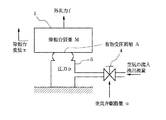
図5に示した従来技術にみられる除振装置の動作を説明する。露光用XYステージなどの精密機器を搭載する除振台1は空気ばね5によって設置床100から浮上支持されている。空気ばね5で除振台1を浮上支持することにより、除振台1を設置床100から振動絶縁することができる。空気ばね5の圧力は空気弁4によって調整される。空気弁4は図6に示すように給気ポート61、排気ポート62および出力圧力ポート63の3ポートを備えたノズルフラッパ型が一般的である。出力圧力は空気弁駆動量(フラッパ開度)に応じて変化する。空気弁駆動量と出力圧力の特性を図7に示す。図7のように、空気弁駆動量−出力圧力特性は非直線的でヒステリシスがあり、非線形性が強い。また、一般に空気ばねは応答が遅く圧力の定位性が悪い。そこで、空気弁4を用いて空気ばね5の圧力を調整する場合は、空気ばね5の圧力を計測しその計測信号に応じて空気弁駆動量を調整するというように、圧力のフィードバック制御を行なうことが多い。
【0005】
図5において、圧力センサ3は空気ばね5の圧力を計測する。圧力目標生成器11は、空気ばね5が除振台1を浮上支持した定常状態の圧力に対する目標値を出力する。圧力補償器12は、後述する変位補償器9および加速度補償器10の出力信号と圧力目標生成器11の出力信号との和に対して、圧力センサ3の出力信号が一致するような補償を行なう。パワー増幅器13は圧力補償器11の出力に応じて空気弁4にパワーを供給し、空気弁4を駆動する。このような圧力のフィードバック制御によって、空気ばね5の圧力を所望の値に制御する。
【0006】
また、変位センサ2は除振台1および空気ばね5の変位を計測する。変位目標生成器7は除振台1および空気ばね5の浮上変位に対する目標値を出力する。変位補償器9は変位目標生成器7の出力信号と変位センサ2の出力信号の差がゼロとなるような補償を行なう。これによって除振台1および空気ばね5の浮上変位を一定に保持する。加速度センサ6は除振台1の振動を計測する。加速度補償器10は加速度センサ6の出力信号に補償を行ない、加速度の負帰還系を形成する。これによって除振台1に発生する振動を抑制する。
【0007】
【発明が解決しようとする課題】
空気ばねを用いた除振装置では、空気弁の非線形特性を補正するため、そして空気ばねの圧力の定位性を改善するため、空気ばねの圧力を圧力センサで計測しその出力信号に応じて空気弁を駆動する、いわゆる圧力のフィードバック制御が行なわれている。ところが、空気ばねに対して圧力のフィードバック制御を行なうと、空気ばねの剛性が低下して除振台の振動が増大してしまうという問題点があった。空気ばねが浮上支持する除振台は、除振台に作用する重力と空気ばねからの支持力とが一致する状態で平衡している。空気ばねからの支持力は、空気ばねと除振台の接触部における有効受圧面積に空気ばねの圧力を乗じて定まるものである。半導体製造装置において除振台に載置される露光用XYステージの駆動反力など、何らかの外乱力のため除振台に振動が発生した場合、本来、除振台の変位に応じて空気ばねの容積が変化し空気ばねの圧力が変わるので、除振台を平衡状態へ戻すような、変位に比例した平衡状態への復元力が空気ばねから除振台に作用する。これが空気ばねの剛性である。圧力のフィードバック制御は空気ばねの圧力を一定に保持するように機能するので、除振台の変位と空気ばねの容積変化が生じても空気ばねの圧力は変化しない。すなわち、空気ばねの剛性が低下して、除振台に平衡状態への復元力が作用しない。よって、圧力のフィードバック制御を行なうと、除振台に外乱力など何らかの要因で振動が発生した場合、空気ばねの剛性低下のため除振台の振動が増大してしまうという問題があった。従来の除振装置において、圧力のフィードバック制御による空気ばねの剛性低下を解決しているものは見受けられない。
【0008】
本発明はこのような事情を考慮してなされたものである。すなわち、本発明の目的は、空気ばねの剛性低下を招くことなく空気ばねの圧力のフィードバック制御を行なうことができる除振装置を提供することにある。
【0009】
【課題を解決するための手段】
上記目的を達成するために、本発明による除振装置は、除振台と、前記除振台を支持する空気ばねと、前記空気ばねの圧力を調整する空気弁と、前記除振台の変位を計測する変位センサと、前記除振台の変位に対する目標値を出力する変位目標生成器と、前記変位目標生成器の出力信号と前記変位センサの出力信号との差信号に補償を施し前記除振台の変位を制御する変位補償器と、前記除振台の振動を計測する加速度センサと、前記加速度センサの出力信号に補償を施して前記変位補償器の入力側に負帰還する加速度補償器と、前記空気ばねの圧力を計測する圧力センサと、前記空気ばねの圧力に対する目標値を出力する圧力目標生成器と、前記変位補償器および前記圧力目標生成器の出力信号と前記圧力センサの出力信号との合成信号に補償を施し前記空気ばねの圧力を制御する圧力補償器と、前記圧力補償器の出力信号に応じて前記空気弁を駆動するパワー増幅器と、ローカットフィルタと比例ゲイン要素を有する剛性補償器であり、かつ、前記変位センサの出力信号に補償を施し前記圧力補償器の入力側に負帰還して空気ばねの剛性を制御する剛性補償器とを有することを特徴とする。
【0011】
【作用】
空気ばねは露光用XYステージ等の精密機器を搭載する除振台を浮上支持する。空気弁は空気ばねの圧力を調整する。圧力センサは空気ばねの圧力を測定する。
圧力目標生成器は空気ばねが除振台を浮上支持した定常状態の圧力に対する目標値を出力する。圧力補償器は、剛性補償器および変位補償器および加速度補償器の出力信号と圧力目標生成器の出力信号との和に対して、圧力センサの出力信号が一致するような補償を行なう。パワー増幅器は圧力補償器の出力に応じて空気弁にパワーを供給し、空気弁を駆動する。
【0012】
変位センサは除振台の変位および空気ばねの浮上変位を計測する。変位目標生成器は除振台の変位および空気ばねの変位に対する目標値を出力する。変位補償器は除振台が所望の浮上位置へ定位するように変位目標生成器の出力信号と変位センサの出力信号との差がゼロとなるような補償を行なう。
加速度センサは除振台に固定されており、除振台に生じる振動を加速度信号として計測する。加速度補償器は加速度センサの出力信号に補償を行ない、加速度の負帰還を形成する。これによって除振台へダンピングを付与する。
【0013】
ローカットフィルタと比例ゲイン要素を有する剛性補償器は、除振台および空気ばねへ剛性を付与するように、変位センサの出力信号に補償を行なう。空気ばねが浮上支持する除振台は、除振台に作用する重力と空気ばねからの支持力とが一致する状態で平衡している。半導体製造装置において除振台に載置される露光用XYステージの駆動反力など、何らかの外乱力のため除振台に振動が発生した場合、剛性補償器はアクチュエータである空気ばねを介して除振台の変位あるいは空気ばねの変位に比例した平衡状態への復元力が除振台へ作用するように機能する。
【0014】
このように、圧力のフィードバック制御を行なっても、剛性補償器の機能により空気ばねの剛性低下は生じない。圧力のフィードバック制御は空気弁の非線形特性を補正し空気ばねの圧力の定位性を改善する。同時に、空気ばねの剛性低下は生じないので、振動抑制性能の良好な除振装置を実現することができる。
【0015】
【実施例】
本発明による除振装置の実施例について、図面に基づき詳細に説明する。図1は本発明の一実施例に係る除振装置の構成を示す。同図において、除振台1は空気ばね5によって浮上支持されている。空気ばね5は除振台1を浮上支持する支持脚であると同時に、除振台1の振動を抑制するため空気ばね5の圧力変化により除振台1へ制振力を作用させるアクチュエータでもある。空気ばね5の圧力は空気弁4によって調整される。
【0016】
圧力のフィードバック制御は次のように実現されている。圧力センサ3は空気ばね5の圧力を計測する。圧力目標生成器11は空気ばね5が除振台1を浮上支持した定常状態の圧力に対する目標値を出力する。圧力補償器12は、後述する剛性補償器8および変位補償器9および加速度補償器10の出力信号と圧力目標生成器11の出力信号との和に対して、圧力センサ3の出力信号が一致するような補償を行なう。パワー増幅器13は圧力補償器11の出力に応じて空気弁4にパワーを供給し、空気弁4を駆動する。このような圧力のフィードバック制御によって、空気ばね5の圧力を所望の値に制御する。
【0017】
変位センサ2は除振台1の変位および空気ばね5の変位を計測する。ここでいう空気ばね5の変位とは空気ばね5のストロークのことであり、除振台1の変位と同一である。変位目標生成器7は除振台1の変位および空気ばね5の浮上変位に対する目標値を出力する。変位補償器9は除振台1が所望の浮上位置へ定位するように変位目標生成器7の出力信号と変位センサ2の出力信号との差がゼロとなるような補償を行なう。変位補償器9は、その入力信号の積分で空気ばね5の圧力が制御されるように設計するのが常套手段である。変位目標生成器7の出力信号に対して除振台1の変位をオーバーシュートすることなくすみやかに収束させるためである。
【0018】
加速度センサ6は除振台1に固定されており、除振台1に生じる振動を加速度信号として計測する。加速度補償器10は加速度センサ6の出力信号に補償を行ない、加速度の負帰還を形成する。前述したように、変位補償器9はその入力信号の積分で空気ばね5の圧力が制御されるように設計しているので、加速度補償器10が加速度センサ6の出力に比例した補償値を生成し、この補償値を変位補償器9へ入力すれば、加速度の積分、すなわち速度に比例した制振力を除振台1に作用させることができる。これによって除振台1へダンピングを与え、除振台1に生じる振動を効果的に抑制している。
【0019】
ローカットフィルタ14と比例ゲイン要素15を有する剛性補償器8は、除振台1および空気ばね5へ剛性を付与するように、変位センサ2の出力信号に補償を行なう。空気ばね5が浮上支持する除振台1は、除振台1に作用する重力と空気ばね5からの支持力とが一致する状態で平衡している。半導体製造装置において除振台1に載置される露光用XYステージの駆動反力など、何らかの外乱力のため除振台1に振動が発生した場合、剛性補償器8はアクチュエータである空気ばね5を介して除振台1の変位あるいは空気ばね5の変位に比例した平衡状態への復元力が除振台1へ作用するように機能する。これによって、除振台1および空気ばね5に剛性を与え、除振台1に生じる振動を効果的に抑制している。
【0020】
剛性補償器8と変位補償器9はどちらも変位センサ2の信号を入力としているが、これまで説明したように両者の機能は全く異なっている。剛性補償器8は除振台1の変位あるいは空気ばね5の変位に比例した平衡状態への復元力を除振台1へ作用させるように機能する。これによって、前述した圧力のフィードバックによる空気ばね5の剛性低下を回避することができる。変位補償器9は除振台1が所望の浮上位置へオーバーシュートすることなく定位するように、変位目標生成器7の出力信号と変位センサ2の出力信号との差の積分で除振台1へ力が作用するように機能する。したがって、変位補償器9の機能によって空気ばね5へ剛性を付与することはできない。剛性とは変位に比例した平衡状態への復元力のことだからである。
【0021】
以下、剛性補償器8の動作をさらに詳しく説明する。
図2は除振台1、空気弁4および空気ばね5からなる部分の動力学モデルを示す。除振台1は質量Μの質量要素としてモデル化できる。その変位をx、除振台1に作用する外乱力をf、また除振台1が空気ばね5から力を受ける部分の有効受圧面積をAとする。空気弁4は空気弁駆動量uに応じて空気の流入流出流量と空気ばね5の圧力pを調整する。圧力pは平衡状態からの変動量であるとして、図2より除振台1の運動に関して(1)式が得られる。また空気ばね5の圧力に関して(2)式が成立する。
【0022】
【数1】

(2)式において、左辺の圧力pに掛かる係数ωは空気ばね5の機械的パラメータから定まる物理量である。また、右辺の空気弁駆動量uに掛かる係数Gq は空気弁4の圧力ゲインである。同じく右辺で除振台1の変位xを含む項は変位xによって空気ばね5の圧力pが変化することを表わしており、Gv はその影響係数である。(1)式および(2)式をラプラス変換することにより、図2の動力学モデルを数学的に示した図3のブロック線図が得られる。図3において、記号sはラプラス演算子を表わす。図3より、入力を空気弁駆動量uおよび外乱力f、出力を除振台1の変位xとした入出力式は(3)式のようになる。(3)式においては、左辺のAGv s/(s+ω)が空気ばね5の剛性を表わしている。
【0024】
【数2】
本実施例による除振装置の動作を数学的に示したブロック線図が図4である。図4は剛性補償器8の動作を説明するのに必要十分な要素のみを示しており、変位補償器9、加速度補償器10など他の構成要素は省略している。図4において圧力補償器12は比例演算器でありそのゲインをGとする。また剛性補償器8の伝達関数をGk とする。入力を外乱力f、出力を除振台1の変位xとした図4の入出力式は(4)式のとおりである。
【0026】
【数3】
もしも剛性補償器8がなくてGk =0であったとしたら、(4)式の入出力式は(5)式のようになる。この場合、空気ばね5の剛性を表わす剛性項は(5)式の左辺よりAGv s/(s+ω+Gq G)であるが、圧力補償器12のゲインGが剛性項の分母にあるので、ゲインGが大きいほど剛性項は小さくなる。つまり、圧力のフィードバックループのゲインGを大きくするほど空気ばね5の剛性は低下することが(5)式からわかる。
【0028】
【数4】
剛性補償器8は圧力のフィードバック制御による空気ばね5の剛性低下を回避するように機能する。(4)式からわかるように、剛性補償器8の動作によって、空気ばね5の剛性項はAGv s/(s+ω+Gq G)+AGv /(s+ω+Gq G)xGq GGk /Gv となっている。すなわち、剛性補償器8の伝達関数Gk を大きくとるほど剛性項も大きくなるので、空気ばね5にとって必要な剛性が確保できる。伝達関数Gk は、具体的には次のように設計すればよい。まず、圧力のフィードバック制御を行なわない場合、空気ばね5の剛性項は(3)式左辺よりAGv s/(s+ω)であった。伝達関数Gk は、本発明による除振装置の入出力式である(4)式の剛性項がこれに一致するように設計する。(3)式と(4)式を比較すれば、剛性補償器8の伝達関数Gk は(6)式のように定まる。
【0030】
【数5】
(6)式で定めた伝達関数Gk を本実施例による除振装置の入出力式である(4)式に代入すると(7)式が得られる。(7)式の左辺と、圧力のフィードバック制御を行なわない場合の入出力式である(3)式の左辺は全く同一である。剛性補償器8の動作によって、圧力のフィードバック制御を行なわない場合と全く同一な空気ばね5の剛性を確保できることがわかる。また、(6)式で示される剛性補償器8の伝達関数Gk はローカットフィルタを表わす伝達関数s/(s+ω) と比例ゲインGv (ω+Gq G)/Gq Gとの直列結合で構成されている。本実施例による除振装置は、剛性補償器8がローカットフィルタ14と比例ゲイン要素15を有することを特徴としている。
【0032】
【数6】
このように、剛性補償器8の動作によって空気ばね5の剛性低下を回避することができるので、本実施例による除振装置は好適な振動抑制性能を実現している。
なお、本発明による除振装置は図1に示した実施形態に限定されるものではない。空気ばねの剛性低下を生じることなく空気ばねの圧力のフィードバック制御を行なうことができる除振装置であるという本発明の本質は、除振台の形状やそれを支持する空気ばねの台数と配置などを問わず実施できる。また、本発明による除振装置を有する半導体製造装置は、逐次駆動型、走査型のいずれにおいても実現できる。
【0034】
これまで用いた数式記号を次にまとめて列記する。
M:除振台1の質量
A:空気ばね5の有効受圧面積
x:除振台1の変位
p:空気ばね5の圧力
u:空気弁駆動量
f:除振台1に作用する外乱力
ω:空気ばね5の機械的パラメータから定まる物理量
Gq :空気弁4の圧力ゲイン
Gv :除振台1の変位xから空気ばね5の圧力pへの影響係数
G:圧力補償器12が比例演算器であるときのゲイン
Gk :剛性補償器8の伝達関数
【0035】
【デバイス生産方法の実施例】
次に上記説明した除振装置を有する露光装置を利用したデバイスの生産方法の実施例を説明する。
図8は微小デバイス(ICやLSI等の半導体チップ、液晶パネル、CCD、薄膜磁気ヘッド、マイクロマシン等)の製造のフローを示す。ステップ1(回路設計)ではデバイスのパターン設計を行なう。ステップ2(マスク製作)では設計したパターンを形成したマスクを製作する。一方、ステップ3(ウエハ製造)ではシリコンやガラス等の材料を用いてウエハを製造する。ステップ4(ウエハプロセス)は前工程と呼ばれ、上記用意したマスクとウエハを用いて、リソグラフィ技術によってウエハ上に実際の回路を形成する。次のステップ5(組み立て)は後工程と呼ばれ、ステップ4によって作製されたウエハを用いて半導体チップ化する工程であり、アッセンブリ工程(ダイシング、ボンディング)、パッケージング工程(チップ封入)等の工程を含む。ステップ6(検査)ではステップ5で作製された半導体デバイスの動作確認テスト、耐久性テスト等の検査を行なう。こうした工程を経て半導体デバイスが完成し、これが出荷(ステップ7)される。
【0036】
図9は上記ウエハプロセスの詳細なフローを示す。ステップ11(酸化)ではウエハの表面を酸化させる。ステップ12(CVD)ではウエハ表面に絶縁膜を形成する。ステップ13(電極形成)ではウエハ上に電極を蒸着によって形成する。ステップ14(イオン打込み)ではウエハにイオンを打ち込む。ステップ15(レジスト処理)ではウエハに感光剤を塗布する。ステップ16(露光)では上記説明した除振装置を有する露光装置によってマスクの回路パターンをウエハに焼付露光する。ステップ17(現像)では露光したウエハを現像する。ステップ18(エッチング)では現像したレジスト像以外の部分を削り取る。ステップ19(レジスト剥離)ではエッチングが済んで不要となったレジストを取り除く。これらのステップを繰り返し行なうことによって、ウエハ上に多重に回路パターンが形成される。
本実施例の生産方法を用いれば、従来は製造が難しかった高集積度のデバイスを低コストに製造することができる。
【0037】
【発明の効果】
以上説明したように、本発明によれば、空気ばねの剛性を低下させずに空気ばねの圧力のフィードバック制御を行なうことができる除振装置を提供することができる。本発明による除振装置においては、圧力のフィードバック制御が空気弁の非線形特性を補正し、空気ばねの圧力の定位性を改善する。同時に、従来技術で問題となっていた空気ばねの剛性低下は生じないので、好適な振動抑制性能を実現することができる。
【図面の簡単な説明】
【図1】 本発明の一実施例に係る除振装置の構成図である。
【図2】 除振台と空気ばねの動力学モデルを示す図面である。
【図3】 除振台と空気ばねの動力学モデルを数学的に示す図面である。
【図4】 本発明による除振装置の動作を数学的に示す図面である。
【図5】 従来技術による除振装置を示す図面である。
【図6】 空気弁の構造を示す図面である。
【図7】 空気弁の特性を示す図面である。
【図8】 微小デバイスの製造の流れを示す図である。
【図9】 図8におけるウエハプロセスの詳細な流れを示す図である。
【符号の説明】
1:除振台、2:変位センサ、3:圧力センサ、4:空気弁、5:空気ばね、6:加速度センサ、7:変位目標生成器、8:剛性補償器、9:変位補償器、10: 加速度補償器、11: 圧力目標生成器、12: 圧力補償器、13:パワー増幅器、14:ローカットフィルタ、15:比例ゲイン要素。[0001]
BACKGROUND OF THE INVENTION
The present invention relates to an anti-vibration apparatus for reducing vibration transmission from an apparatus installation base in a precision instrument such as an exposure apparatus used for manufacturing a semiconductor device such as an IC, LSI, or CCD, or a liquid crystal device such as a liquid crystal panel.
[0002]
[Prior art]
As precision instruments such as electron microscopes and semiconductor manufacturing equipment become more precise, there is a need for higher performance of precision vibration isolation devices that mount them. In particular, in a semiconductor manufacturing apparatus, a vibration isolator that eliminates vibrations transmitted from the outside such as installation floor vibrations as much as possible is necessary in order to perform appropriate and rapid exposure. This is because, in the semiconductor manufacturing apparatus, the exposure XY stage must be completely stopped when the semiconductor wafer is exposed. Further, since the XY stage for exposure is characterized by an intermittent operation called step-and-repeat, repeated step motion excites vibration of the vibration isolation table itself. Therefore, the vibration isolator is required to achieve a good balance between the vibration isolation performance against external vibration and the vibration suppression performance against vibration generated by the operation of the mounted device itself.
[0003]
In response to such demands, so-called active type vibration isolation devices have been put into practical use in which vibration of a vibration isolation table is measured by a vibration sensor and an vibration isolation table is driven by an actuator in accordance with the measurement signal. In an active vibration isolator, an air spring is generally used as an actuator. This is because the air spring can easily generate a thrust sufficient to support a heavy object such as a semiconductor manufacturing apparatus. FIG. 5 shows a configuration of a typical vibration isolation device found in the prior art.
[0004]
The operation of the vibration isolator shown in the prior art shown in FIG. 5 will be described. An anti-vibration table 1 on which precision equipment such as an XY stage for exposure is mounted is levitated and supported from an
[0005]
In FIG. 5, the pressure sensor 3 measures the pressure of the
[0006]
The
[0007]
[Problems to be solved by the invention]
In an anti-vibration device using an air spring, the pressure of the air spring is measured by a pressure sensor in order to correct the non-linear characteristics of the air valve and to improve the localization of the pressure of the air spring. So-called pressure feedback control for driving the valve is performed. However, when pressure feedback control is performed on the air spring, there is a problem in that the rigidity of the air spring decreases and the vibration of the vibration isolation table increases. The vibration isolation table that is levitated and supported by the air spring is balanced in a state in which the gravity acting on the vibration isolation table and the support force from the air spring coincide. The support force from the air spring is determined by multiplying the effective pressure receiving area at the contact portion between the air spring and the vibration isolation table by the pressure of the air spring. When vibration is generated in the vibration isolation table due to some disturbance force such as the driving reaction force of the exposure XY stage placed on the vibration isolation table in the semiconductor manufacturing apparatus, the air spring is originally changed according to the displacement of the vibration isolation table. Since the volume changes and the pressure of the air spring changes, a restoring force to the equilibrium state proportional to the displacement, such as returning the vibration isolation table to the equilibrium state, acts on the vibration isolation table from the air spring. This is the stiffness of the air spring. Since the pressure feedback control functions to keep the pressure of the air spring constant, the pressure of the air spring does not change even if the displacement of the vibration isolation table and the volume change of the air spring occur. That is, the rigidity of the air spring is lowered, and the restoring force to the equilibrium state does not act on the vibration isolation table. Therefore, when pressure feedback control is performed, there is a problem that when vibration is generated in the vibration isolation table due to some factor such as a disturbance force, the vibration of the vibration isolation table increases due to a decrease in rigidity of the air spring. In the conventional vibration isolator, there is no one that solves the decrease in rigidity of the air spring by pressure feedback control.
[0008]
The present invention has been made in consideration of such circumstances. That is, an object of the present invention is to provide a vibration isolation device capable of performing feedback control of the pressure of the air spring without causing a decrease in rigidity of the air spring.
[0009]
[Means for Solving the Problems]
In order to achieve the above object, a vibration isolation device according to the present invention includes a vibration isolation table, an air spring that supports the vibration isolation table, an air valve that adjusts the pressure of the air spring, and a displacement of the vibration isolation table . A displacement sensor that measures the displacement, a displacement target generator that outputs a target value for the displacement of the vibration isolation table , and a difference signal between the output signal of the displacement target generator and the output signal of the displacement sensor to compensate the displacement. a displacement compensator for controlling the displacement of the vibration table, and an acceleration sensor for measuring the vibration of the vibration isolating stand, the acceleration compensator is negatively fed back to the input side of the displacement compensator applies compensation to the output signal of the acceleration sensor A pressure sensor that measures the pressure of the air spring, a pressure target generator that outputs a target value for the pressure of the air spring, an output signal of the displacement compensator and the pressure target generator, and an output of the pressure sensor To the composite signal with the signal A pressure compensator that compensates and controls the pressure of the air spring, a power amplifier that drives the air valve according to an output signal of the pressure compensator, a stiffness compensator having a low-cut filter and a proportional gain element, And a stiffness compensator that compensates the output signal of the displacement sensor and negatively feeds back to the input side of the pressure compensator to control the stiffness of the air spring.
[0011]
[Action]
The air spring levitates and supports a vibration isolation table on which precision equipment such as an exposure XY stage is mounted. The air valve regulates the pressure of the air spring. The pressure sensor measures the pressure of the air spring.
The pressure target generator outputs a target value for the steady-state pressure in which the air spring levitates and supports the vibration isolation table. The pressure compensator performs compensation such that the output signal of the pressure sensor matches the sum of the output signal of the stiffness compensator, the displacement compensator, and the acceleration compensator and the output signal of the pressure target generator. The power amplifier supplies power to the air valve according to the output of the pressure compensator and drives the air valve.
[0012]
The displacement sensor measures the displacement of the vibration isolation table and the floating displacement of the air spring. The displacement target generator outputs target values for the vibration isolation table displacement and the air spring displacement. The displacement compensator performs compensation so that the difference between the output signal of the displacement target generator and the output signal of the displacement sensor becomes zero so that the vibration isolation table is localized at a desired floating position.
The acceleration sensor is fixed to the vibration isolation table, and measures vibration generated on the vibration isolation table as an acceleration signal. The acceleration compensator compensates for the output signal of the acceleration sensor and forms a negative feedback of acceleration. This gives damping to the vibration isolation table.
[0013]
A stiffness compensator having a low cut filter and a proportional gain element compensates for the output signal of the displacement sensor so as to impart stiffness to the vibration isolation table and the air spring. The vibration isolation table that is levitated and supported by the air spring is balanced in a state in which the gravity acting on the vibration isolation table and the support force from the air spring coincide. When vibration is generated in the vibration isolation table due to some disturbance force such as the driving reaction force of the exposure XY stage placed on the vibration isolation table in the semiconductor manufacturing equipment, the stiffness compensator is removed via an air spring as an actuator. It functions so that a restoring force to an equilibrium state proportional to the displacement of the shaking table or the displacement of the air spring acts on the vibration isolation table.
[0014]
As described above, even if the pressure feedback control is performed, the rigidity of the air spring does not decrease due to the function of the rigidity compensator. Pressure feedback control corrects the non-linear characteristics of the air valve and improves the localization of the air spring pressure. At the same time, since the rigidity of the air spring does not decrease, a vibration isolator having good vibration suppression performance can be realized.
[0015]
【Example】
Embodiments of the vibration isolator according to the present invention will be described in detail with reference to the drawings. FIG. 1 shows the configuration of a vibration isolation device according to an embodiment of the present invention. In the figure, the vibration isolation table 1 is supported by levitation by an
[0016]
Pressure feedback control is realized as follows. The pressure sensor 3 measures the pressure of the
[0017]
The
[0018]
The acceleration sensor 6 is fixed to the vibration isolation table 1 and measures vibration generated in the vibration isolation table 1 as an acceleration signal. The
[0019]
A
[0020]
The
[0021]
Hereinafter, the operation of the
FIG. 2 shows a dynamic model of a part composed of the vibration isolation table 1, the
[0022]
[Expression 1]
In the equation (2), the coefficient ω applied to the pressure p on the left side is a physical quantity determined from the mechanical parameters of the
[0024]
[Expression 2]
FIG. 4 is a block diagram mathematically showing the operation of the vibration isolator according to the present embodiment. FIG. 4 shows only elements necessary and sufficient for explaining the operation of the
[0026]
[Equation 3]
If there is no
[0028]
[Expression 4]
The
[0030]
[Equation 5]
Substituting (6) is an input-output type vibration isolator according to the present embodiment the transfer function G k was determined by formula (4) (7) is obtained. The left side of equation (7) is exactly the same as the left side of equation (3), which is an input / output equation when pressure feedback control is not performed. It can be seen that the rigidity of the
[0032]
[Formula 6]
As described above, since the rigidity of the
The vibration isolator according to the present invention is not limited to the embodiment shown in FIG. The essence of the present invention that it is a vibration isolation device capable of performing feedback control of the pressure of the air spring without causing a decrease in rigidity of the air spring is the shape of the vibration isolation table, the number and arrangement of the air springs supporting the vibration isolation table, etc. It can be implemented regardless. Moreover, the semiconductor manufacturing apparatus having the vibration isolator according to the present invention can be realized by either a sequential drive type or a scanning type.
[0034]
The mathematical symbols used so far are listed below.
M: Mass of the vibration isolation table 1 A: Effective pressure receiving area of the air spring 5 x: Displacement of the vibration isolation table 1 p: Pressure of the air spring 5 u: Air valve drive amount f: Disturbance force ω acting on the vibration isolation table 1 : physical quantity determined from the mechanical parameters of the air spring 5 G q: pressure gain of the air valve 4 G v: influence coefficient from the displacement x of the
[Example of device production method]
Next, an embodiment of a device production method using the exposure apparatus having the vibration isolator described above will be described.
FIG. 8 shows the flow of manufacturing a microdevice (semiconductor chip such as IC or LSI, liquid crystal panel, CCD, thin film magnetic head, micromachine, etc.). In step 1 (circuit design), a device pattern is designed. In step 2 (mask production), a mask on which the designed pattern is formed is produced. On the other hand, in step 3 (wafer manufacture), a wafer is manufactured using a material such as silicon or glass. Step 4 (wafer process) is called a pre-process, and an actual circuit is formed on the wafer by lithography using the prepared mask and wafer. The next step 5 (assembly) is referred to as a post-process, and is a process for forming a semiconductor chip using the wafer produced in
[0036]
FIG. 9 shows a detailed flow of the wafer process. In step 11 (oxidation), the wafer surface is oxidized. In step 12 (CVD), an insulating film is formed on the wafer surface. In step 13 (electrode formation), an electrode is formed on the wafer by vapor deposition. In step 14 (ion implantation), ions are implanted into the wafer. In step 15 (resist process), a photosensitive agent is applied to the wafer. In step 16 (exposure), the circuit pattern of the mask is printed on the wafer by exposure using the exposure apparatus having the vibration isolator described above. In step 17 (development), the exposed wafer is developed. In step 18 (etching), portions other than the developed resist image are removed. In step 19 (resist stripping), unnecessary resist after etching is removed. By repeating these steps, multiple circuit patterns are formed on the wafer.
By using the production method of this embodiment, a highly integrated device that has been difficult to manufacture can be manufactured at low cost.
[0037]
【The invention's effect】
As described above, according to the present invention, it is possible to provide a vibration isolator that can perform feedback control of the pressure of the air spring without reducing the rigidity of the air spring. In the vibration isolator according to the present invention, the pressure feedback control corrects the non-linear characteristic of the air valve and improves the localization of the pressure of the air spring. At the same time, since the rigidity of the air spring, which has been a problem in the prior art, does not deteriorate, a suitable vibration suppression performance can be realized.
[Brief description of the drawings]
FIG. 1 is a configuration diagram of a vibration isolation device according to an embodiment of the present invention.
FIG. 2 is a drawing showing a dynamic model of a vibration isolation table and an air spring.
FIG. 3 is a drawing mathematically showing a dynamic model of a vibration isolation table and an air spring.
FIG. 4 is a drawing mathematically showing the operation of the vibration isolator according to the present invention.
FIG. 5 is a view showing a vibration isolator according to the prior art.
FIG. 6 is a view showing a structure of an air valve.
FIG. 7 is a view showing characteristics of an air valve.
FIG. 8 is a diagram showing a flow of manufacturing a microdevice.
9 is a diagram showing a detailed flow of the wafer process in FIG. 8. FIG.
[Explanation of symbols]
1: vibration isolator, 2: displacement sensor, 3: pressure sensor, 4: air valve, 5: air spring, 6: acceleration sensor, 7: displacement target generator, 8: stiffness compensator, 9: displacement compensator, 10: acceleration compensator, 11: pressure target generator, 12: pressure compensator, 13: power amplifier, 14: low cut filter, 15: proportional gain element.
Claims (3)
前記除振台を支持する空気ばねと、
前記空気ばねの圧力を調整する空気弁と、
前記除振台の変位を計測する変位センサと、
前記除振台の変位に対する目標値を出力する変位目標生成器と、
前記変位目標生成器の出力信号と前記変位センサの出力信号との差信号に補償を施し前記除振台の変位を制御する変位補償器と、
前記除振台の振動を計測する加速度センサと、
前記加速度センサの出力信号に補償を施して前記変位補償器の入力側に負帰還する加速度補償器と、
前記空気ばねの圧力を計測する圧力センサと、
前記空気ばねの圧力に対する目標値を出力する圧力目標生成器と、
前記変位補償器および前記圧力目標生成器の出力信号と前記圧力センサの出力信号との合成信号に補償を施し前記空気ばねの圧力を制御する圧力補償器と、
前記圧力補償器の出力信号に応じて前記空気弁を駆動するパワー増幅器と、
ローカットフィルタと比例ゲイン要素を有する剛性補償器であり、かつ、前記変位センサの出力信号に補償を施し前記圧力補償器の入力側に負帰還して空気ばねの剛性を制御する剛性補償器とを有することを特徴とする除振装置。A vibration isolation table,
An air spring that supports the vibration isolation table;
An air valve for adjusting the pressure of the air spring;
A displacement sensor for measuring the displacement of the anti-vibration table,
A displacement target generator for outputting a target value for the displacement of the vibration isolation table;
A displacement compensator for controlling the displacement of the anti-vibration table performs compensation on the difference signal between the output signal of the output signal of the displacement sensor of the displacement target generator,
An acceleration sensor for measuring vibration of the vibration isolation table;
An acceleration compensator that compensates the output signal of the acceleration sensor and negatively feeds back to the input side of the displacement compensator;
A pressure sensor for measuring the pressure of the air spring;
A pressure target generator for outputting a target value for the pressure of the air spring;
A pressure compensator for compensating the combined signal of the output signal of the displacement compensator and the pressure target generator and the output signal of the pressure sensor to control the pressure of the air spring;
A power amplifier that drives the air valve in response to an output signal of the pressure compensator;
A stiffness compensator having a low-cut filter and a proportional gain element, and compensating the output signal of the displacement sensor and negatively feeding back to the input side of the pressure compensator to control the stiffness of the air spring. An anti-vibration device comprising:
Priority Applications (1)
| Application Number | Priority Date | Filing Date | Title |
|---|---|---|---|
| JP34363898A JP4165844B2 (en) | 1998-11-18 | 1998-11-18 | Vibration isolator |
Applications Claiming Priority (1)
| Application Number | Priority Date | Filing Date | Title |
|---|---|---|---|
| JP34363898A JP4165844B2 (en) | 1998-11-18 | 1998-11-18 | Vibration isolator |
Publications (3)
| Publication Number | Publication Date |
|---|---|
| JP2000154843A JP2000154843A (en) | 2000-06-06 |
| JP2000154843A5 JP2000154843A5 (en) | 2008-04-10 |
| JP4165844B2 true JP4165844B2 (en) | 2008-10-15 |
Family
ID=18363083
Family Applications (1)
| Application Number | Title | Priority Date | Filing Date |
|---|---|---|---|
| JP34363898A Expired - Fee Related JP4165844B2 (en) | 1998-11-18 | 1998-11-18 | Vibration isolator |
Country Status (1)
| Country | Link |
|---|---|
| JP (1) | JP4165844B2 (en) |
Families Citing this family (11)
| Publication number | Priority date | Publication date | Assignee | Title |
|---|---|---|---|---|
| US6731372B2 (en) * | 2001-03-27 | 2004-05-04 | Nikon Corporation | Multiple chamber fluid mount |
| JP2003202051A (en) * | 2002-01-04 | 2003-07-18 | Canon Inc | Vibration-proofing device |
| WO2005085671A1 (en) * | 2004-03-08 | 2005-09-15 | Nikon Corporation | Vibration isolator, exposure apparatus, and vibration isolating method |
| JP2006250291A (en) * | 2005-03-11 | 2006-09-21 | Tokyo Univ Of Agriculture & Technology | Vibration isolating device |
| JP5002759B2 (en) * | 2005-10-13 | 2012-08-15 | 国立大学法人東京工業大学 | Vibration isolator and vibration isolation method |
| JP4113960B2 (en) * | 2006-04-28 | 2008-07-09 | 国立大学法人東京工業大学 | Gas spring type vibration isolator and control method thereof |
| DE102009009562A1 (en) * | 2009-02-19 | 2010-09-09 | Integrated Dynamics Engineering Gmbh | Combined motion sensor for use in feedback control systems for vibration isolation |
| CN101818777B (en) * | 2010-05-07 | 2011-08-10 | 华中科技大学 | Self-adaptive damping variable ultra-precise vibration absorber |
| JP6278676B2 (en) * | 2013-11-29 | 2018-02-14 | キヤノン株式会社 | Vibration reducing apparatus, lithographic apparatus, and article manufacturing method |
| CN108425378A (en) * | 2018-04-08 | 2018-08-21 | 北京航天希尔测试技术有限公司 | A kind of large size air supporting vibration damping ground |
| CN112197927A (en) * | 2020-10-10 | 2021-01-08 | 北京航宇振控科技有限责任公司 | Automatic air floatation support system applied to vibration simulation device |
-
1998
- 1998-11-18 JP JP34363898A patent/JP4165844B2/en not_active Expired - Fee Related
Also Published As
| Publication number | Publication date |
|---|---|
| JP2000154843A (en) | 2000-06-06 |
Similar Documents
| Publication | Publication Date | Title |
|---|---|---|
| US6286644B1 (en) | Active vibration isolator, exposure apparatus, exposure method and device manufacturing method | |
| JP4109891B2 (en) | Active vibration control apparatus, exposure apparatus, and device manufacturing method | |
| US20040164253A1 (en) | Vibration control of an object | |
| EP1124078B1 (en) | Active anti-vibration apparatus and exposure apparatus | |
| JPH11294520A (en) | Vibration-eliminating device, exposing device using it, manufacture of device and vibration-eliminating method | |
| US6771354B2 (en) | Vibration damping apparatus, control method therefor, exposure apparatus having the vibration damping apparatus, maintenance method therefor, semiconductor device fabrication method, and semiconductor fabrication factory | |
| US20070097340A1 (en) | Active damper with counter mass to compensate for structural vibrations of a lithographic system | |
| JP4165844B2 (en) | Vibration isolator | |
| US6864962B2 (en) | Active anti-vibration apparatus and exposure apparatus and device manufacturing method using the same | |
| US6213443B1 (en) | Anti-vibration apparatus and exposure apparatus using the same | |
| JP2003256050A (en) | Vibration controller, vibration controlling method, exposure system and manufacturing method of device | |
| US20180367067A1 (en) | Motor with force constant modeling and identification for flexible mode control | |
| JP2003202051A (en) | Vibration-proofing device | |
| US20050140961A1 (en) | Anti-vibration system, method of controlling the same, exposure apparatus, and device manufacturing method | |
| JPH0783276A (en) | Control device of vertical air spring type vibration eliminating board | |
| JPH11102858A (en) | Stage positioning control device and active vibration-proof device | |
| JP2000208402A (en) | Vibration removing device | |
| JP2000136845A (en) | Active vibration insulating device and exposure device using it | |
| JP2001345244A (en) | Method of controlling stage, stage device, aligner, and method of manufacturing device | |
| JP2000068195A (en) | Device manufacturing equipment | |
| JP2000220690A (en) | Active vibration-absorbing device, exposure device and manufacture of device | |
| JP2002367893A (en) | Aligner | |
| JP2000228343A (en) | Active vibration-isolating device, projection aligner, and device-manufacturing method | |
| JP2001221279A (en) | Active vibration damping device | |
| JP2000018314A (en) | Vibration resistant device, exposure device, and manufacture of device |
Legal Events
| Date | Code | Title | Description |
|---|---|---|---|
| A621 | Written request for application examination |
Free format text: JAPANESE INTERMEDIATE CODE: A621 Effective date: 20051116 |
|
| A521 | Written amendment |
Free format text: JAPANESE INTERMEDIATE CODE: A523 Effective date: 20080212 |
|
| RD02 | Notification of acceptance of power of attorney |
Free format text: JAPANESE INTERMEDIATE CODE: A7422 Effective date: 20080227 |
|
| A131 | Notification of reasons for refusal |
Free format text: JAPANESE INTERMEDIATE CODE: A131 Effective date: 20080312 |
|
| A977 | Report on retrieval |
Free format text: JAPANESE INTERMEDIATE CODE: A971007 Effective date: 20080314 |
|
| TRDD | Decision of grant or rejection written | ||
| A01 | Written decision to grant a patent or to grant a registration (utility model) |
Free format text: JAPANESE INTERMEDIATE CODE: A01 Effective date: 20080723 |
|
| A01 | Written decision to grant a patent or to grant a registration (utility model) |
Free format text: JAPANESE INTERMEDIATE CODE: A01 |
|
| A61 | First payment of annual fees (during grant procedure) |
Free format text: JAPANESE INTERMEDIATE CODE: A61 Effective date: 20080728 |
|
| R150 | Certificate of patent or registration of utility model |
Free format text: JAPANESE INTERMEDIATE CODE: R150 |
|
| FPAY | Renewal fee payment (event date is renewal date of database) |
Free format text: PAYMENT UNTIL: 20110808 Year of fee payment: 3 |
|
| FPAY | Renewal fee payment (event date is renewal date of database) |
Free format text: PAYMENT UNTIL: 20120808 Year of fee payment: 4 |
|
| FPAY | Renewal fee payment (event date is renewal date of database) |
Free format text: PAYMENT UNTIL: 20120808 Year of fee payment: 4 |
|
| FPAY | Renewal fee payment (event date is renewal date of database) |
Free format text: PAYMENT UNTIL: 20130808 Year of fee payment: 5 |
|
| LAPS | Cancellation because of no payment of annual fees |