US7053660B2 - Output buffer circuit and control method therefor - Google Patents
Output buffer circuit and control method therefor Download PDFInfo
- Publication number
- US7053660B2 US7053660B2 US11/121,130 US12113005A US7053660B2 US 7053660 B2 US7053660 B2 US 7053660B2 US 12113005 A US12113005 A US 12113005A US 7053660 B2 US7053660 B2 US 7053660B2
- Authority
- US
- United States
- Prior art keywords
- output
- signal
- control
- circuit
- input signal
- Prior art date
- Legal status (The legal status is an assumption and is not a legal conclusion. Google has not performed a legal analysis and makes no representation as to the accuracy of the status listed.)
- Expired - Lifetime
Links
Images


Classifications
-
- H—ELECTRICITY
- H03—ELECTRONIC CIRCUITRY
- H03K—PULSE TECHNIQUE
- H03K19/00—Logic circuits, i.e. having at least two inputs acting on one output; Inverting circuits
- H03K19/0175—Coupling arrangements; Interface arrangements
- H03K19/0185—Coupling arrangements; Interface arrangements using field effect transistors only
-
- H—ELECTRICITY
- H03—ELECTRONIC CIRCUITRY
- H03K—PULSE TECHNIQUE
- H03K19/00—Logic circuits, i.e. having at least two inputs acting on one output; Inverting circuits
- H03K19/003—Modifications for increasing the reliability for protection
- H03K19/00346—Modifications for eliminating interference or parasitic voltages or currents
- H03K19/00361—Modifications for eliminating interference or parasitic voltages or currents in field effect transistor circuits
-
- H—ELECTRICITY
- H03—ELECTRONIC CIRCUITRY
- H03K—PULSE TECHNIQUE
- H03K17/00—Electronic switching or gating, i.e. not by contact-making and –breaking
- H03K17/16—Modifications for eliminating interference voltages or currents
- H03K17/161—Modifications for eliminating interference voltages or currents in field-effect transistor switches
- H03K17/165—Modifications for eliminating interference voltages or currents in field-effect transistor switches by feedback from the output circuit to the control circuit
- H03K17/166—Soft switching
- H03K17/167—Soft switching using parallel switching arrangements
Definitions
- the present invention relates to an output buffer circuit, and, more particularly, to an output buffer circuit that outputs an output signal having gentle rising and falling edges and a slew-rate control type output buffer circuit.
- an interface such as USB (Universal Serial Bus), which is used to connect a computer to a keyboard and achieves slow data transfer, is equipped with an output buffer circuit which has long signal rising and falling times.
- USB Universal Serial Bus
- the use of a signal which has long rising and falling times makes it unnecessary to provide a bus cable with a shield for preventing undesirable radiation.
- FIG. 1 is a schematic circuit diagram of a first prior art output buffer circuit 11 .
- the output buffer circuit 11 has a drive circuit 12 and first and second control circuits 13 and 14 .
- the drive circuit 12 has a P channel (PMOS) transistor TP 1 and an N channel (NMOS) transistor TN 1 which are connected in series between a high-potential power supply VDD and a low-potential power supply VSS.
- a node between the PMOS and NMOS transistors TP 1 and TN 1 is connected to an output terminal 15 of the output buffer circuit 11 .
- the first control circuit 13 has a PMOS transistor TP 2 and two NMOS transistors TN 2 and TN 3 , which are connected in series between the high-potential power supply VDD and low-potential power supply VSS.
- a node between the PMOS transistor TP 2 and the adjacent NMOS transistor TN 2 is connected to the gate of the PMOS transistor TP 1 .
- An external input signal VIN is applied to the gates of the individual transistors TP 2 , TN 2 and TN 3 .
- the transistors TP 2 , TN 2 and TN 3 supply a control signal VP to the gate of the output transistor TP 1 .
- the second control circuit 14 has two PMOS transistors TP 3 and TP 4 and an NMOS transistor TN 4 , which are connected in series between the high-potential power supply VDD and low-potential power supply VSS.
- a node between the PMOS transistor TP 4 and the adjacent NMOS transistor TN 4 is connected to the gate of the NMOS transistor TN 1 .
- the external input signal VIN is applied to the gates of the individual transistors TP 3 , TP 4 and TN 4 .
- the transistors TP 3 , TP 4 and TN 4 supply the control signal VN to the gate of the output transistor TN 1 .
- Each of the PMOS and NMOS transistors TP 1 and TN 1 has a relatively large transistor size (gate width). That is, each of the PMOS and NMOS transistors TP 1 and TN 1 has a low impedance with respect to the output terminal 15 .
- the NMOS transistors TN 2 and TN 3 of the first control circuit 13 control the amount of current flowing into the low-potential power supply VSS, so that the control signal VP having a gentle falling edge is supplied to the PMOS transistor TP 1 . As a result, an external output signal VOUT which has a gentle rising edge is output from the output terminal 15 .
- the PMOS transistors TP 3 and TP 4 of the second control circuit 14 control the amount of current flowing out of the high-potential power supply VDD, so that a control signal VN having a gentle rising edge is supplied to the NMOS transistor TN 1 . As a result, the external output signal VOUT which has a gentle falling edge is output from the output terminal 15 .
- the waveform of the output signal VOUT has gentle transition by controlling the waveform transition times of the control signals VP and VN that are respectively applied to the gates of the output transistors TP 1 and TN 1 by the first and second control circuits 13 and 14 .
- the minimum values and maximum values of the rising time and falling time of the output signal VOUT are specified by specifications.
- the waveforms of the control signals VP and VN are greatly affected by variations in the sizes of the individual transistors TP 2 –TP 4 and TN 2 –TN 4 or variations in the wiring capacitances between the first and second control circuits 13 and 14 and the output transistors TP 1 and TN 2 , which are factors of the manufacturing process, a variation in supply voltage or a temperature change. That is, variations in the rising and falling times of the external output signal VOUT are increased, so that the rising and falling times exceed the specified ranges.
- FIG. 2 is a schematic circuit diagram of a second prior art slew-rate control type output buffer circuit 211 .
- the output buffer circuit 211 adjusts the inclination (slew rate) of the input waveform to the gate of an output driving transistor to reduce the consumed current at the time the output signal varies.
- the output buffer circuit 211 has output driving transistors (simply called “output transistors”) T 1 and T 2 , slew-rate control circuits 212 and 213 which perform the ON/OFF control of the respective output transistors T 1 and T 2 in response to the external input signal VIN, and a delay circuit 214 .
- the first output transistor T 1 which is a PMOS transistor
- the second output transistor T 2 which is an NMOS transistor
- the first output transistor T 1 has a source connected to the high-potential power supply VDD and a drain connected to an output terminal 215 , with a control signal VP from the first control circuit 212 being applied to the gate of the transistor T 1 .
- the second output transistor T 2 has a source connected to the low-potential power supply VSS and a drain connected to the output terminal 215 , with a control signal VN from the second control circuit 213 being applied to the gate of the transistor T 2 .
- the first control circuit 212 has a PMOS transistor T 11 and NMOS transistors T 12 and T 13 , connected in series between the high-potential power supply VDD and low-potential power supply VSS, and an NMOS transistor T 14 connected in parallel to the NMOS transistor T 13 .
- the PMOS transistor T 11 has a source connected to the high-potential power supply VDD and a drain connected to the drain of the NMOS transistor T 12 , with an external input signal VIN being applied to the gates of both transistors T 11 and T 12 .
- the source of the NMOS transistor T 12 is connected to the drain of the NMOS transistor T 13 whose source is connected to the low-potential power supply VSS.
- the NMOS transistor T 14 has a relatively large ON resistance and its gate is connected to the high-potential power supply VDD. Therefore, the NMOS transistor T 14 is normally ON and serves as a resistor element.
- the second control circuit 213 has PMOS transistors T 21 and T 22 and an NMOS transistor T 23 , connected in series between the high-potential power supply VDD and low-potential power supply VSS, and a PMOS transistor T 24 connected in parallel to the PMOS transistor T 21 .
- the PMOS transistor T 21 has a source connected to the high-potential power supply VDD and a drain connected to the source of the PMOS transistor T 22 , with the external input signal VIN being applied to the gates of both transistors T 21 and T 22 .
- the drain of the PMOS transistor T 22 is connected to the drain of the NMOS transistor T 23 whose source is connected to the low-potential power supply VSS.
- the PMOS transistor T 24 has a relatively large ON resistance and its gate is connected to the low-potential power supply VSS. Therefore, the PMOS transistor T 24 is normally ON and serves as a resistor element.
- the delay circuit 214 is comprised of an inverter circuit which has an input terminal to which the external input signal VIN is applied and an output terminal connected to the gates of the NMOS transistor T 13 and PMOS transistor T 21 .
- the output buffer circuit 211 operates as follows.
- the first (PMOS) transistor T 11 is turned off immediately, and the NMOS transistor T 12 is turned on.
- the H-level external input signal VIN which has been delayed by the delay circuit 214 is applied to the gate of the NMOS transistor T 13 . That is, the H-level inverted external input signal VIN before the change of the external input signal VIN is applied to the gate of the NMOS transistor T 13 for a predetermined time. Therefore, the NMOS transistor T 13 is enabled for a predetermined delay time so that the control signal VP rapidly falls as indicated by * 1 in FIG. 3 .
- the NMOS transistor T 13 When the level of the delay signal from the delay circuit 214 changes to the L level from the H level after the predetermined delay time passes, the NMOS transistor T 13 is turned off so that the control signal VP gently falls due to the large ON resistance of the NMOS transistor T 14 . Therefore, the time needed for the first output transistor T 1 to be turned on completely is longer than the time for the second output transistor T 2 to be turned off, thus generating the external output signal VOUT that gently changes to the H level from the L level.
- the NMOS transistor T 23 is turned off immediately, and the PMOS transistor T 22 is turned on.
- the L-level external input signal VIN which has been delayed by the delay circuit 214 is applied to the gate of the PMOS transistor T 21 . That is, the L-level inverted external input signal VIN before the change of the external input signal VIN is applied to the gate of the PMOS transistor T 21 for a predetermined time. Therefore, the PMOS transistor T 21 is enabled for a predetermined delay time so that the control signal VP rapidly rises as indicated by * 2 in FIG. 3 .
- the PMOS transistor T 21 When the level of the delay signal from the delay circuit 214 changes to the H level from the L level after the predetermined delay time passes, the PMOS transistor T 21 is turned off so that the control signal VN gently rises due to the large ON resistance of the PMOS transistor T 24 .
- the time needed for the second output transistor T 2 to be turned on completely becomes longer than the time for the first output transistor T 1 to be turned off, thus generating the external output signal VOUT that gently changes to the L level from the H level.
- FIG. 3 shows the waveforms of the control signals VP and VN, the external output signal VOUT and a switching current I which flows through the output transistors T 1 and T 2 .
- the control signal VP gently falls and the control signal VN drastically falls.
- the output transistors T 1 and T 2 are not turned on at the same time.
- the output transistors T 1 and T 2 are not turned on simultaneously. This reduces the current I that flows through the output transistors T 1 and T 2 at the time of switching, thus decreasing the consumed current of the output buffer circuit 211 .
- the control signals VP and VN drastically change as indicated by * 1 and * 2 . Because the delay time of the delay circuit 214 is set to the time for the control signals VP and VN to reach the threshold voltages of the output transistors T 1 and T 2 , the rising and falling responses of the external output signal VOUT become faster, thus decreasing the propagation delay time of the output buffer circuit 211 . Since the slew rate of the external output signal VOUT is lower than that of the output signal of an ordinary CMOS inverter, the output buffer circuit 211 is suited for slow (low-frequency) data transfer.
- the control signals VP and VN cannot change in response to a high frequency, so that the external output signal VOUT cannot fully swing.
- the control signals VP and VN cannot reach the H level and L level because of a fast change in external input signal VIN as shown in FIG. 4( b ).
- the external output signal VOUT does not reach the H level (the level of the high-potential power supply VDD) as shown in FIG. 4( c ).
- the external output signal VOUT that has an H-level pulse width W 2 narrower than an H-level pulse width W 1 of the external input signal VIN is generated, which may cause an error in data transfer.
- the pulse width W 2 also becomes narrower by variations in the process, temperature and supply voltage (PTV variations), which may result in malfunction.
- a method of controlling an output buffer circuit includes a first drive circuit for receiving an input signal having a sharp waveform and generating an output signal that has a gentle waveform and is output from an output terminal of the output buffer circuit, and a second drive circuit connected to the output terminal and having a lower output impedance than the first drive circuit.
- the method includes the steps of changing the output signal in accordance with a change in the input signal using the first drive circuit and driving the second drive circuit after the output signal is changed by a predetermined amount.
- a method of controlling an output buffer circuit includes first and second drive circuits.
- the first drive circuit includes a first output transistor connected between a first power supply and an output terminal of the output buffer circuit and a second output transistor connected between a second power supply and the output terminal.
- the first and second output transistors generate an output signal having gentle waveform in response to an input signal having a sharp waveform.
- the second drive circuit includes a third output transistor connected between the first power supply and the output terminal and a fourth output transistor connected between the second power supply and the output terminal.
- the third and fourth output transistors have lower impedances than the first and second output transistors.
- an output buffer circuit in a third aspect of the present invention, includes a first drive circuit for receiving an input signal having a sharp waveform and generating an output signal that has a gentle waveform and is output from an output terminal of the output buffer circuit.
- a second drive circuit is connected to the output terminal and has a lower output impedance than the first drive circuit.
- a delay circuit is connected to the output terminal to delay the output signal and generating a delayed output signal.
- a first control circuit is connected between the delay circuit and the second drive circuit to receive the input signal and the delayed output signal and generate first control signal for driving the second drive circuit.
- an output buffer circuit in a fourth aspect of the present invention, includes first and second output transistors connected in series between a first power supply and a second power supply.
- First and second control circuits are connected to the first and second output transistors to receive an input signal and respectively generate first and second control signals for controlling the first and second output transistors.
- the first and second output transistors generate an output signal at an output terminal of the output buffer circuit.
- a third control circuit is connected between the output terminal and the first and second control circuits to receive the input signal and the output signal and control a slew rate of the output signal by controlling slew rates of the first and second control signals in accordance with the input signal and the output signal.
- the third control circuit controls the first and second control circuits when the first and second output transistors are turned off to generate the first and second control signal in accordance with the input signal, and controls the first and second control circuits when the first and second output transistors are turned on such that the first and second control signals sharply rise or fall in response to a change in the input signal, gently rise or fall after a predetermined time elapses, and thereafter sharply rise or fall when the output signal reaches a predetermined level.
- FIG. 1 is a schematic circuit diagram of a first prior art output buffer circuit
- FIG. 2 is a schematic circuit diagram of a second prior art output buffer circuit
- FIG. 3 is a waveform diagram for explaining the operation of the output buffer circuit in FIG. 2 ;
- FIGS. 4( a )– 4 ( c ) are waveform diagrams for explaining the high-frequency operation of the output buffer circuit in FIG. 2 ;
- FIG. 5 is a schematic circuit diagram of an output buffer circuit according to a first embodiment of the present invention.
- FIG. 6 is a waveform diagram for explaining the operation of the output buffer circuit in FIG. 5 ;
- FIG. 7 is a waveform diagram for explaining the transition period of the output signal of the output buffer circuit in FIG. 5 ;
- FIG. 8 is a schematic circuit diagram of an output buffer circuit according to a second embodiment of the present invention.
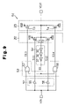
- FIG. 9 is a schematic circuit diagram of an output buffer circuit according to a third embodiment of the present invention.
- FIG. 10 is a schematic circuit diagram of an output buffer circuit according to a fourth embodiment of the present invention.
- FIG. 11 is a waveform diagram for explaining the operation of the output buffer circuit in FIG. 10 ;
- FIGS. 12( a )– 12 ( c ) are waveform diagrams for explaining the high-frequency operation of the output buffer circuit in FIG. 10 ;
- FIG. 13 is a schematic circuit diagram of an output buffer circuit according to a fifth embodiment of the present invention.
- FIG. 14 is a waveform diagram for explaining the operation of the output buffer circuit in FIG. 13 .
- FIG. 5 is a schematic circuit diagram of an output buffer circuit 21 according to the first embodiment of the present invention.
- the output buffer circuit 21 has first and second drive circuits 22 and 23 , first and second control circuits 24 and 25 , and a delay circuit 26 .
- the output buffer circuit 21 receives an external input signal VIN from an input terminal 27 and generates an external output signal VOUT which has gentle rising and falling edges corresponding to a predetermined specification.
- the output buffer circuit 21 outputs the external output signal VOUT from an output terminal 28 .
- the output buffer circuit 21 has a low impedance characteristic with respect to the output terminal 28 .
- the first drive circuit 22 generates the external output signal VOUT that has gentle rising and falling edges corresponding to a predetermined specification, and the second drive circuit 23 is provided for the low impedance characteristic.
- the first drive circuit 22 includes a PMOS transistor (first output transistor) T 1 and an NMOS transistor (second output transistor) T 2 , connected in series between a high-potential power supply VDD and a low-potential power supply VSS.
- the output transistors T 1 and T 2 have transistor sizes (gate widths) set such that the external output signal VOUT gently rises and falls in response to a sudden change in the input signal VIN. That is, the output transistors T 1 and T 2 have the transistor sizes so set as to have a high impedance characteristic.
- a first control signal Si from the first control circuit 24 is applied to the gate of the first output transistor T 1
- a second control signal S 2 from the first control circuit 24 is applied to the gate of the second output transistor T 2 .
- the second drive circuit 23 includes a PMOS transistor (third output transistor) T 3 and an NMOS transistor (fourth output transistor) T 4 , connected in series between the high-potential power supply VDD and the low-potential power supply VSS.
- the output transistors T 3 and T 4 have transistor sizes (gate widths) so set as to have a low impedance characteristic when the external output signal VOUT is in a static state.
- a third control signal S 3 from the second control circuit 25 is applied to the gate of the third output transistor T 3
- a fourth control signal S 4 from the second control circuit 25 is applied to the gate of the fourth output transistor T 4 .
- the first control circuit 24 includes two inverter circuits 31 and 32 .
- the first inverter circuit 31 receives the external input signal VIN and generates the first control signal S 1 which is the external input signal VIN inverted.
- the second inverter circuit 32 receives the external input signal VIN and generates the second control signal S 2 which is the external input signal VIN inverted.
- the second control circuit 25 includes a NAND gate 33 and a NOR gate 34 .
- the NAND gate 33 receives the external input signal VIN and a delay signal SD from the delay circuit 26 and performs a NAND operation on the external input signal VIN and delay signal SD to generate the third control signal S 3 .
- the NOR gate 34 receives the external input signal VIN and the delay signal SD from the delay circuit 26 and performs a NOR operation on the external input signal VIN and delay signal SD to generate the fourth control signal S 4 .
- the delay circuit 26 includes an even number of (four in this case) inverter circuits 35 to 38 connected in series.
- the first inverter circuit 35 is supplied with the external output signal VOUT and the last inverter circuit 38 outputs the delay signal SD.
- the external output signal VOUT is therefore delayed by a predetermined time in accordance with the number of the inverter circuits 35 - 38 .
- the number of the inverter circuits 35 - 38 is set such that the second drive circuit 23 operates with a predetermined delay time after the first drive circuit 22 operates in accordance with the characteristic of the first drive circuit 22 . That is, because the output transistors T 1 and T 2 of the first drive circuit 22 have a high impedance characteristic, the external output signal VOUT that is generated by the first drive circuit 22 has gentle rising and falling edges. After the external output signal VOUT rises or falls sufficiently, the second drive circuit 23 is driven. The second drive circuit 23 has a low impedance characteristic. Therefore, the first drive circuit 22 causes the external output signal VOUT to gently rise and fall, and the second drive circuit 23 secures the low-output impedance characteristic.
- the period from the point of a change in the external output signal VOUT to the point of a change in delay signal SD is set as a first period (period A 1 in FIG. 6 ), and a period after the delay signal SD changes is set as a second period (period B 1 in FIG. 6 ).
- the first control circuit 24 In response to the rising of the input signal VIN, the first control circuit 24 causes the first and second control signals S 1 and S 2 to fall, thus turning on the first output transistor T 1 and turning off the second output transistor T 2 .
- the second control circuit 25 outputs the H-level third control signal S 3 and causes the fourth control signal S 4 to fall in response to the rising of the input signal VIN. This keeps the third output transistor T 3 turned off and turns off the fourth output transistor T 4 . As a result, the first output transistor T 1 having a high impedance characteristic causes the external output signal VOUT to slowly rise to the H level from the L level.
- the first and second output transistors T 1 and T 2 may be turned on simultaneously.
- the amounts of currents flowing in the output transistors T 1 and T 2 are smaller than the amounts of currents flowing in the conventional output transistors TP 1 and TN 1 that have a low impedance characteristic.
- the second control circuit 25 In response to the rising of the delay signal SD, the second control circuit 25 causes the third control signal S 3 to fall, thus turning on the third output transistor T 3 .
- the ON action of the third output transistor T 3 causes the output buffer circuit 21 to have a low-output impedance characteristic.
- the fourth output transistor T 4 is turned off first and then the third output transistor T 3 is turned on after a predetermined time elapses. Therefore, the output transistors T 3 and T 4 are not turned on simultaneously, so that the through currents that flow in the output transistors T 3 and T 4 are almost zero.
- the period from the point of a change in the external output signal VOUT to the point of a change in delay signal SD is set as a third period (period A 2 in FIG. 6 ), and a period after the delay signal SD changes is set as a fourth period (period B 2 in FIG. 6 ).
- the first control circuit 24 In response to the falling of the input signal VIN, the first control circuit 24 causes the first and second control signals S 1 and S 2 to rise, thus turning off the first output transistor T 1 and turning on the second output transistor T 2 .
- the second control circuit 25 In response to the falling of the input signal VIN, the second control circuit 25 causes the third control signal S 3 to rise and outputs the L-level fourth control signal S 4 . This turns off the third output transistor T 3 and keeps the fourth output transistor T 4 turned off. As a result, the second output transistor T 2 having a high impedance characteristic causes the external output signal VOUT to slowly fall to the L level from the H level.
- the second control circuit 25 causes the fourth control signal S 4 to rise, thus turning on the fourth output transistor T 4 .
- the ON action of the fourth output transistor T 4 causes the output buffer circuit 21 to have a low-output impedance characteristic.
- the third output transistor T 3 is turned off first and then the fourth output transistor T 4 is turned on after a predetermined time elapses. Therefore, the output transistors T 3 and T 4 are not turned on simultaneously, so that the through currents that flow in output transistors T 3 and T 4 are almost zero (0).
- FIG. 7 shows the waveforms of the external output signals VOUT from the output buffer circuit 21 of the first embodiment and the conventional output buffer circuit 11 .
- V 1 min indicates the waveform when the transition time of the external output signal VOUT of the output buffer circuit 21 is minimum
- V 1 max indicates the waveform when the transition time of the external output signal VOUT of the output buffer circuit 21 is maximum.
- V 2 min indicates the waveform when the transition time of the external output signal VOUT of the conventional output buffer circuit 11 is minimum
- V 2 max indicates the waveform when the transition time of the external output signal VOUT of the conventional output buffer circuit 11 is maximum.
- the transition time changes depending on variations of production processes and the like.
- the first and second output transistors T 1 and T 2 have a high impedance characteristic and the first and second control signals S 1 and S 2 which show sharp rising and falling are applied to the gates of the first and second output transistors T 1 and T 2 .
- the first and second control signals S 1 and S 2 are unlikely to be affected by production variations, a variation in transition time is less than that in the prior art.
- the output buffer circuit 21 of the first embodiment has the following advantages.
- the first drive circuit 22 generates the signal VOUT having a gentle waveform in response to the input signal VIN having a sharp waveform, and the second drive circuit 23 has a lower output impedance than the first drive circuit 22 .
- the first and second control circuits 24 and 25 drive the second drive circuit 23 after the output signal VOUT is sufficiently changed by the first drive circuit 22 in response to the input signal VIN and the delay signal SD from the delay circuit 26 .
- the control signals S 1 and S 2 that are applied to the gates of the respective output transistors T 1 and T 2 of the first drive circuit 22 are unlikely to be affected by production variations. Consequently, the first drive circuit 22 generates the output signal VOUT having a gentle waveform so that a variation in the transition time of the output signal VOUT becomes smaller due to the low impedance characteristic of the second drive circuit 23 in the static state of the output signal VOUT.
- the second control circuit 25 turns on the fourth output transistor T 4 after the third output transistor T 3 is turned off.
- the second control circuit 25 also turns on the third output transistor T 3 after the fourth output transistor T 4 is turned off.
- the third and fourth output transistors T 3 and T 4 are not turned on simultaneously, so that the through currents do not flow into the third and fourth output transistors T 3 and T 4 . This prevents the consumed current from increasing.
- FIG. 8 is a schematic circuit diagram of an output buffer circuit 41 according to the second embodiment of the present invention.
- the output buffer circuit 41 alters the output impedance value.
- the output buffer circuit 41 includes first and second drive circuits 22 and 42 , first and second control circuits 24 and 43 , a delay circuit 26 and three inverter circuits 44 , 45 and 46 .
- the second drive circuit 42 includes a plurality of (three in this case) sub-drive circuits 42 a, 42 b and 42 c, and the second control circuit 43 includes three associated sub-control circuits 43 a, 43 b and 43 c.
- the sub-drive circuits 42 a, 42 b and 42 c respectively include PMOS transistors (output transistors) T 3 a to T 3 c and NMOS transistors (output transistors) T 4 a to T 4 c. At least one of the PMOS transistors T 3 a –T 3 c has a different impedance from those of the other.
- the sub-control circuits 43 a, 43 b and 43 c respectively include NAND gates 47 a to 47 c which generate control signals S 3 a to S 3 c for controlling the respective output transistors T 3 a –T 3 c, and NOR gates 48 a to 48 c which generate control signals S 4 a to S 4 c for controlling the respective output transistors T 4 a –T 4 c.
- Each of the NAND gates 47 a – 47 c is a 3-input element which receives the external input signal VIN, the delay signal SD and a select signal SEL 0 , SEL 1 or SEL 2 .
- Each of the NOR gates 48 a – 48 c is a 3-input element which receives the external input signal VIN, the delay signal SD and the inverted select signal SEL 0 , SEL 1 or SEL 2 , from an inverter circuit 44 , 45 or 46 .
- the control signals S 3 a –S 3 c and S 4 a –S 4 c are supplied to at least one of the sub-drive circuits 42 a, 42 b and 42 c in response to the H-level select signal, thus enabling that sub-drive circuit.
- the output impedance of the output buffer circuit 41 is determined by at least one sub-drive circuit 42 a – 42 c that has been enabled.
- the second embodiment has the following advantage.
- the output buffer circuit 41 has the second drive circuit 42 that includes three sub-drive circuits 42 a – 42 c having different impedances. In accordance with the select signals SEL 1 to SEL 2 , at least one of the sub-drive circuits 42 a – 42 c is enabled to select the output impedance when the output signal VOUT is in a static state.
- FIG. 9 is a schematic circuit diagram of an inversion output buffer circuit 51 according to the third embodiment of the present invention.
- the inversion output buffer circuit 51 generates the output signal VOUT whose phase is opposite to the phase of the input signal VIN.
- the output buffer circuit 51 has first and second drive circuits 22 and 23 , first and second control circuits 52 and 53 and a delay circuit 54 .
- the first control circuit 52 includes two buffer circuits 55 and 56 .
- the buffer circuits 55 and 56 respectively apply first and second control signals S 11 and S 12 in phase with the input signal VIN to the gates of first and second output transistors T 1 and T 2 .
- the second control circuit 53 has an OR gate 57 , which generates a third control signal S 13 that is supplied to the gate of a third output transistor T 3 , and an AND gate 58 , which generates a fourth control signal S 14 that is supplied to the gate of a fourth output transistor T 4 .
- the delay circuit 54 which includes an odd number of inverter circuits 35 , 36 and 37 , delays the external output signal VOUT and generates an inverted signal of the external output signal VOUT.
- the output buffer circuit 51 operates in a manner similar to that of the output buffer circuit 21 of the first embodiment.
- the output buffer circuit 51 may be adapted to the second embodiment. As the first and second control signals S 11 and S 12 are in phase with the input signal VIN, the input signal VIN may be applied directly to the gates of the first and second output transistors T 1 and T 2 . In this case, the first control circuit may be omitted.
- the first to third embodiments may be embodied into an output buffer circuit which has only the output transistors T 1 and T 3 connected to the high-potential power supply VDD or an open-drain type output buffer circuit which has only the output transistors T 2 and T 4 connected to the low-potential power supply VSS.
- FIG. 10 is a schematic circuit diagram of a slew-rate control type output buffer circuit 231 according to the fourth embodiment of the present invention.
- the output buffer circuit 231 has first and second output driving transistors (hereinafter simply called “output transistors”) T 1 and T 2 , first and second slew-rate control circuits (hereinafter simply called “control circuits”) 212 and 213 which perform the ON/OFF control of the respective output transistors T 1 and T 2 in response to the external input signal VIN, a delay circuit 232 and a signal generator 233 .
- the delay circuit 232 which is preferably a buffer circuit, receives the external input signal VIN and generates the delay signal SD which is the external input signal VIN delayed by substantially the same delay time as that of the conventional delay circuit 14 .
- the signal generator 233 includes first and second inverter circuits 234 and 235 , a NAND gate 236 and a NOR gate 237 .
- the first inverter circuit 234 has a low threshold voltage Vt 1 (about the voltage of VOL_max which is the L-level output interface standard for the output buffer circuit 231 ). Based on the threshold voltage Vt 1 , the first inverter circuit 234 supplies an inverted signal S 1 of the external output signal VOUT to the NAND gate 236 .
- the inverted signal S 1 is kept at an L level while the voltage of the external output signal VOUT is higher than the threshold voltage Vt 1 .
- the NAND gate 236 receives the inverted signal S 1 and delay signal SD and performs a NAND operation on the inverted signal S 1 and delay signal SD to generate a first switching control signal S 2 .
- the first switching control signal S 2 is applied to the gate of an NMOS transistor T 13 .
- the first switching control signal S 2 is kept at an L level during the period from the rising of the delay signal SD to the falling of the inverted signal S 1 . That is, the first switching control signal S 2 is kept at the L level until the external output signal VOUT becomes higher than the threshold voltage Vt 1 after a predetermined time has passed since the rising of the external input signal VIN.
- the NMOS transistor T 13 is set off during the period from the rising of the delay signal SD to the falling of the inverted signal S 1 .
- the signal generator 233 turns on the NMOS transistor T 13 for a predetermined time since the rising of the external input signal VIN, temporarily turns off the NMOS transistor T 13 , and turns on the NMOS transistor T 13 again in accordance with the level of the external output signal VOUT.
- the ON/OFF of the NMOS transistor T 13 determines the falling waveform of a control signal VP (i.e., the rising waveform of the external output signal VOUT).
- the control signal VP falls sharply while the NMOS transistor T 13 is on, and falls gently due to the ON resistance of an NMOS transistor T 14 while the NMOS transistor T 13 is off. Therefore, the external output signal VOUT rapidly reaches an operation start point as the NMOS transistor T 13 is turned on at the rising of the external input signal VIN, and the external output signal VOUT gently rises as the NMOS transistor T 13 is turned off.
- the NMOS transistor T 13 is turned on again, causing the external output signal VOUT to sharply rise to the H level.
- the second inverter circuit 235 has a high threshold voltage Vt 2 (about the voltage of VOH_min which is the H-level output interface standard for the output buffer circuit 231 ). Based on the threshold voltage Vt 2 , the second inverter circuit 235 supplies an inverted signal S 3 of the external output signal VOUT to the NOR gate 237 . The inverted signal S 3 is kept at an H level while the voltage of the external output signal VOUT is lower than the threshold voltage Vt 2 .
- the NOR gate 237 receives the inverted signal S 3 and the delay signal SD and performs a NOR operation on the inverted signal S 3 and the delay signal SD to generate a second switching control signal S 4 .
- the second switching control signal S 4 is supplied to the gate of a PMOS transistor T 21 .
- the second switching control signal S 4 is kept at an H level during the period from the falling of the delay signal SD to the rising of the inverted signal S 3 . That is, the second switching control signal S 4 is kept at the H level until the external output signal VOUT becomes lower than the threshold voltage Vt 2 after a predetermined time has passed since the falling of the external input signal VIN.
- the PMOS transistor T 21 is off during the period from the falling of the delay signal SD to the rising of the inverted signal S 3 .
- the signal generator 233 turns on the PMOS transistor T 21 for a predetermined time since the falling of the external input signal VIN, temporarily turns off the PMOS transistor T 21 , and turns on the PMOS transistor T 21 again in accordance with the level of the external output signal VOUT.
- the ON/OFF of the PMOS transistor T 21 determines the rising waveform of a control signal VN (i.e., the falling waveform of the external output signal VOUT). Specifically, the control signal VN rises sharply while the PMOS transistor T 21 is on, and rises gently due to the ON resistance of a PMOS transistor T 24 while the PMOS transistor T 21 is off. Therefore, the external output signal VOUT rapidly reaches the operation start point as the PMOS transistor T 21 is turned on at the falling of the external input signal VIN, and the external output signal VOUT gently falls as the PMOS transistor T 21 is turned off. When the external output signal VOUT exceeds the threshold voltage Vt 2 , the PMOS transistor T 21 is turned on again, causing the external output signal VOUT to sharply fall to the L level.
- VN rising waveform of a control signal VN
- a PMOS transistor T 11 is turned off immediately by the H-level external input signal VIN and an NMOS transistor T 12 is turned on.
- the ON/OFF action of the NMOS transistor T 13 is however controlled by the output signal S 2 from the NAND gate 236 .
- the NAND gate 236 receives the L-level delay signal SD from the delay circuit 232 (the L-level external input signal VIN before being changed) and the H-level inverted signal S 1 from the first inverter circuit 234 , and applies the H-level switching control signal S 2 to the gate of the NMOS transistor T 13 , so that the NMOS transistor T 13 is turned on.
- the ON action of the NMOS transistor T 13 causes the control signal VP to sharply fall from the H level.
- the delay time of the delay circuit 232 is set to the time for the control signal VP to fall down to the threshold voltage of the first output transistor T 1 from the H level.
- the delay signal from the delay circuit 232 changes to the H level from the L level and the switching control signal S 2 changes to the L level from the H level.
- This turns off the NMOS transistor T 13 .
- the NMOS transistor T 14 having a large ON resistance causes the control signal VP to gently fall and causes the external output signal VOUT to gently rise.
- the inverted signal from the inverter circuit 234 changes to the L level from the H level and the switching control signal S 2 changes to the H level from the L level.
- the NMOS transistor T 13 is turned on.
- the turned-on NMOS transistor T 13 causes the control signal VP to sharply fall to the L level. Accordingly, the external output signal VOUT sharply rises to the H level.
- the NMOS transistor T 23 is turned off immediately in response to the L-level external input signal VIN and the PMOS transistor T 22 is turned on.
- the ON/OFF action of the PMOS transistor T 21 is controlled by the switching control signal S 4 from the NOR gate 237 .
- the NOR gate 237 receives the H-level delay signal SD from the delay circuit 232 (the H-level external input signal VIN before being changed) and the L-level inverted signal S 3 from the second inverter circuit 235 , and applies the L-level switching control signal S 4 to the gate of the PMOS transistor T 21 , so that the PMOS transistor T 21 is turned on.
- the ON action of the PMOS transistor T 21 causes the control signal VN to sharply rise from the L level.
- the delay time of the delay circuit 232 is set to the time for the control signal VN to rise to the threshold voltage of the second output transistor T 2 from the L level.
- the delay signal from the delay circuit 232 changes to the L level from the H level and the switching control signal S 4 changes to the H level from the L level.
- This turns off the PMOS transistor T 21 .
- the PMOS transistor T 24 having a large ON resistance causes the control signal VN to gently rise and causes the external output signal VOUT to gently fall.
- the inverted signal from the inverter circuit 235 changes to the H level from the L level and the switching control signal S 4 changes to the L level from the H level.
- This turns on the PMOS transistor T 21 .
- the turned-on PMOS transistor T 21 causes the control signal VN to sharply rise to the H level. Accordingly, the external output signal VOUT sharply falls to the L level.
- the first and second control circuits 212 and 213 and the signal generator 233 cause the control signals VP and VN to sharply rise or fall in accordance with the level of the external output signal VOUT. This brings about only the influence such that the PTV variation changes the rising and falling positions of the control signals VP and VN and the external output signal VOUT with respect to the time. In other words, the pulse width is not affected by production variations (PTV).
- the output buffer circuit 231 can cope with fast (high-frequency) data transfer.
- the control signals VP and VN surely reach the H level or the L level until the external input signal VIN changes, so that the control signals VP and VN swing fully.
- the external output signal VOUT swings fully to generate the external output signal VOUT whose pulse width Wb is substantially equal to the H-level pulse width Wa of the external input signal VIN.
- the output buffer circuit 231 according to the fourth embodiment has the following advantages.
- the control signals VP and VN sharply rise or fall while the control signals VP and VN are gently rising or falling. Consequently, the control signals VP and VN change to the H level and L level in a short period of time and swing fully, and the external output signal VOUT swings fully too. Therefore, the output buffer circuit 231 can cope with fast (high-frequency) data transfer and can thus have a wide frequency band.
- the external output signal VOUT is fed back to the NAND gate 236 and the NOR gate 237 using the first inverter circuit 234 having a low threshold voltage and the second inverter circuit 235 having a high threshold voltage. Therefore, an inflection point appears in the waveform of the external output signal VOUT near the H level or the L level thereof. This reduces the possible noise-oriented interference on the interface with the receiving side. In other words, an inflection point does not appear in the vicinity of the intermediate potential of the external output signal VOUT.
- FIG. 13 is a circuit diagram of an output buffer circuit 241 according to the fifth embodiment of the present invention.
- the output buffer circuit 241 has first and second output transistors T 1 and T 2 , first and second control circuits 212 and 213 which perform the ON/OFF control of the respective output transistors T 1 and T 2 in response to the external input signal VIN, a delay circuit 232 and a signal generator 242 .
- the signal generator 242 includes a NAND gate 236 , a NOR gate 237 and a Schmitt inverter circuit 243 .
- the inverter circuit 243 which has a hysteresis characteristic, receives the external output signal VOUT and supplies the NAND gate 236 and the NOR gate 237 with an inverted signal S 11 of the external output signal VOUT.
- the inverter circuit 243 has a relatively wide hysteresis width, and its L-side threshold voltage VtL is set to about VOL_max which is the L-level output interface standard of the output buffer circuit 241 while its H-side threshold voltage VtH is set to about VOH_min which is the H-level output interface standard.
- the control signal VP is caused to sharply fall from the H level to the threshold voltage of the first output transistor T 1 by the turned-on NMOS transistor T 13 .
- the control signal VP gently falls due to the ON resistance of the NMOS transistor T 14 . Accordingly, the external output signal VOUT rises gently.
- the H-side threshold voltage VtH of the Schmitt inverter circuit 243 is set to about VOH_min which is the H-level output interface standard of the buffer.
- VOH_min is the H-level output interface standard of the buffer.
- the L-side threshold voltage VtL of the Schmitt inverter circuit 243 is set to about VOL_max which is the L-level output interface standard of the buffer.
- VOL_max is the L-level output interface standard of the buffer.
- the output buffer circuit 241 of the fifth embodiment has the following advantages.
- the individual transitional points of a sharp change to a slow change to a sharp change of the control signals VP and VN can be adjusted by adjusting the hysteresis width and threshold voltage of the Schmitt inverter circuit 243 and the delay time of the delay circuit 232 . It is therefore possible to make the output buffer circuit 241 conform to the external interface specifications which define the maximum and minimum standards of the slow and gentle slew rate, so that the external output signal VOUT whose slew rate satisfies the standards can be generated.
- the output buffer circuits according to the fourth and fifth embodiments may be embodied in an inversion type output buffer circuit.
- the inversion type output buffer circuit has an inverter circuit connected to, for example, its input terminal.
- the inversion type output buffer circuit may be constructed by modifying the first and second control circuits 212 and 213 , the delay circuit 232 and the signal generator 233 .
Abstract
Description
Claims (7)
Priority Applications (1)
| Application Number | Priority Date | Filing Date | Title |
|---|---|---|---|
| US11/121,130 US7053660B2 (en) | 2000-03-30 | 2005-05-04 | Output buffer circuit and control method therefor |
Applications Claiming Priority (6)
| Application Number | Priority Date | Filing Date | Title |
|---|---|---|---|
| JP2000-093760 | 2000-03-30 | ||
| JP2000093760A JP3881150B2 (en) | 2000-03-30 | 2000-03-30 | Output buffer circuit control method and output buffer circuit |
| JP2000-102455 | 2000-04-04 | ||
| JP2000102455A JP4137339B2 (en) | 2000-04-04 | 2000-04-04 | Output buffer circuit and semiconductor device |
| US09/735,555 US6924669B2 (en) | 2000-03-30 | 2000-12-14 | Output buffer circuit and control method therefor |
| US11/121,130 US7053660B2 (en) | 2000-03-30 | 2005-05-04 | Output buffer circuit and control method therefor |
Related Parent Applications (1)
| Application Number | Title | Priority Date | Filing Date |
|---|---|---|---|
| US09/735,555 Division US6924669B2 (en) | 2000-03-30 | 2000-12-14 | Output buffer circuit and control method therefor |
Publications (2)
| Publication Number | Publication Date |
|---|---|
| US20050189964A1 US20050189964A1 (en) | 2005-09-01 |
| US7053660B2 true US7053660B2 (en) | 2006-05-30 |
Family
ID=26588864
Family Applications (2)
| Application Number | Title | Priority Date | Filing Date |
|---|---|---|---|
| US09/735,555 Expired - Lifetime US6924669B2 (en) | 2000-03-30 | 2000-12-14 | Output buffer circuit and control method therefor |
| US11/121,130 Expired - Lifetime US7053660B2 (en) | 2000-03-30 | 2005-05-04 | Output buffer circuit and control method therefor |
Family Applications Before (1)
| Application Number | Title | Priority Date | Filing Date |
|---|---|---|---|
| US09/735,555 Expired - Lifetime US6924669B2 (en) | 2000-03-30 | 2000-12-14 | Output buffer circuit and control method therefor |
Country Status (3)
| Country | Link |
|---|---|
| US (2) | US6924669B2 (en) |
| KR (1) | KR100693846B1 (en) |
| TW (1) | TW525345B (en) |
Cited By (15)
| Publication number | Priority date | Publication date | Assignee | Title |
|---|---|---|---|---|
| US20050231251A1 (en) * | 2004-04-16 | 2005-10-20 | Hynix Semiconductor, Inc. | Apparatus and method for adjusting slew rate in semiconductor memory device |
| US20060279356A1 (en) * | 2005-05-31 | 2006-12-14 | Samsung Electronics | Source driver controlling slew rate |
| US20080144407A1 (en) * | 2004-06-08 | 2008-06-19 | Transmeta Corporation | Stacked inverter delay chain |
| US20080197882A1 (en) * | 2007-02-16 | 2008-08-21 | Chi Mei Optoelectronics Corporation | Logic circuits |
| US20090045846A1 (en) * | 2004-06-08 | 2009-02-19 | Transmeta Corporation | Advanced repeater with duty cycle adjustment |
| US7595664B1 (en) * | 2004-06-08 | 2009-09-29 | Robert Paul Masleid | Repeater circuit having different operating and reset voltage ranges, and methods thereof |
| US20090309631A1 (en) * | 2004-06-08 | 2009-12-17 | Robert Paul Masleid | Circuit with enhanced mode and normal mode |
| US7646228B1 (en) | 2004-06-15 | 2010-01-12 | Masleid Robert P | Inverting zipper repeater circuit |
| US7652507B1 (en) | 2004-06-08 | 2010-01-26 | Robert Paul Masleid | Circuits and methods for detecting and assisting wire transitions |
| US7710153B1 (en) | 2006-06-30 | 2010-05-04 | Masleid Robert P | Cross point switch |
| US20100149170A1 (en) * | 2008-12-15 | 2010-06-17 | Da-Rong Huang | Method for driving a display and related display apparatus |
| US20100164578A1 (en) * | 2008-12-29 | 2010-07-01 | Masleid Robert P | Repeater circuit with staged output |
| US8102190B2 (en) | 2004-06-08 | 2012-01-24 | Robert Paul Masleid | Power efficient multiplexer |
| US20120039134A1 (en) * | 2008-08-11 | 2012-02-16 | Jong Yeol Yang | Data output circuit in a semiconductor memory apparatus |
| US20180233179A1 (en) * | 2017-02-13 | 2018-08-16 | SK Hynix Inc. | Data output buffer |
Families Citing this family (39)
| Publication number | Priority date | Publication date | Assignee | Title |
|---|---|---|---|---|
| US6670821B2 (en) * | 2002-01-02 | 2003-12-30 | Broadcom Corporation | Methods and systems for sensing and compensating for process, voltage, temperature, and load variations |
| JP3684210B2 (en) * | 2002-06-05 | 2005-08-17 | 株式会社東芝 | CMOS output buffer circuit |
| JP3808026B2 (en) * | 2002-10-23 | 2006-08-09 | 株式会社ルネサステクノロジ | Semiconductor device |
| DE10355509A1 (en) * | 2003-11-27 | 2005-07-07 | Infineon Technologies Ag | Circuit and method for delayed switching on of an electrical load |
| KR100568875B1 (en) * | 2004-01-13 | 2006-04-10 | 삼성전자주식회사 | Output driver for use in semiconductor device |
| US6980018B2 (en) * | 2004-04-29 | 2005-12-27 | Internatiional Business Machines Corporation | Self limiting gate leakage driver |
| US7215152B2 (en) * | 2004-08-17 | 2007-05-08 | Stmicroelectronics Pvt Ltd. | High performance adaptive load output buffer with fast switching of capacitive loads |
| US7142015B2 (en) * | 2004-09-23 | 2006-11-28 | International Business Machines Corporation | Fast turn-off circuit for controlling leakage |
| KR100613448B1 (en) * | 2004-10-07 | 2006-08-21 | 주식회사 하이닉스반도체 | Data Accelerating Circuit and Data Transmitting Circuit by that |
| US7262637B2 (en) * | 2005-03-22 | 2007-08-28 | Micron Technology, Inc. | Output buffer and method having a supply voltage insensitive slew rate |
| JP2006287353A (en) * | 2005-03-31 | 2006-10-19 | Nec Corp | Clock driver circuit and drive method thereof |
| US7533208B2 (en) * | 2005-09-26 | 2009-05-12 | Silicon Graphics, Inc. | Hot plug control apparatus and method |
| JP4817372B2 (en) * | 2006-03-28 | 2011-11-16 | 富士通セミコンダクター株式会社 | Open drain output circuit |
| US7362136B2 (en) * | 2006-04-04 | 2008-04-22 | Taiwan Semiconductor Manufacturing Co., Ltd. | Dual voltage single gate oxide I/O circuit with high voltage stress tolerance |
| CN101188418B (en) * | 2006-11-16 | 2011-07-27 | 奇美电子股份有限公司 | Logic circuit including single type of transistor and its corresponding application circuit |
| FR2911450A1 (en) * | 2007-01-15 | 2008-07-18 | St Microelectronics Sa | High speed buffer circuit for electronic system, has unit creating overvoltage on inverters, where unit includes control unit constituted of ports and transistors for selectively releasing stored energy |
| US7710168B2 (en) * | 2007-08-17 | 2010-05-04 | National Semiconductor Corporation | Apparatus and method for two tier output stage for switching devices |
| DE102007048646B3 (en) * | 2007-10-10 | 2009-01-22 | Texas Instruments Deutschland Gmbh | Electronic device i.e. integrated electronic device, has gate stage arranged to set configuration signal when decelerated input signal includes logic level that indicates that signal change of input signal does not spread within delay stage |
| TWI436584B (en) * | 2008-02-13 | 2014-05-01 | Etron Technology Inc | Output circuit with reducing overshoot function |
| KR100956781B1 (en) * | 2008-09-10 | 2010-05-12 | 주식회사 하이닉스반도체 | Data Output Circuit |
| DE102009012166B4 (en) * | 2009-03-06 | 2010-12-16 | Siemens Medical Instruments Pte. Ltd. | Hearing apparatus and method for reducing a noise for a hearing device |
| TWI388120B (en) * | 2009-12-17 | 2013-03-01 | Phison Electronics Corp | Driving circuit for input/output interface |
| WO2013179093A1 (en) * | 2012-05-31 | 2013-12-05 | Freescale Semiconductor, Inc. | Integrated circuit comprising an io buffer driver and method therefor |
| KR101900722B1 (en) * | 2012-07-10 | 2018-09-20 | 삼성전자주식회사 | Circuit for Driving Power MOS Transistor |
| KR101412949B1 (en) * | 2012-10-08 | 2014-06-26 | 삼성전기주식회사 | Driver amplifier circuit and power amplifier using the same |
| CN103095275B (en) * | 2012-11-30 | 2016-03-02 | 北京控制工程研究所 | High-reliability large-power drive circuit and driving method |
| CN105027443B (en) * | 2013-03-09 | 2018-12-11 | 密克罗奇普技术公司 | Inductive load driver conversion rate control device |
| KR20150005299A (en) * | 2013-07-05 | 2015-01-14 | 에스케이하이닉스 주식회사 | Output apparatus and output system including the same |
| CN104242905B (en) * | 2014-09-03 | 2017-06-06 | 灿芯半导体(上海)有限公司 | USB output circuits |
| CN104980146A (en) * | 2015-06-17 | 2015-10-14 | 北京兆易创新科技股份有限公司 | Drive control device and PADIO output circuit with same |
| KR20170068720A (en) * | 2015-12-09 | 2017-06-20 | 에스케이하이닉스 주식회사 | Inverter circuit |
| KR102424450B1 (en) * | 2016-02-22 | 2022-07-25 | 에스케이하이닉스 주식회사 | Input output circuit and integrated circuit using the same |
| US10270444B1 (en) * | 2018-04-04 | 2019-04-23 | Hewlett Packard Enterprise Development Lp | Delayed boost of driver output signals |
| CN109149772B (en) * | 2018-09-11 | 2020-09-18 | 北京空间机电研究所 | Load isolation and passive matching remote control instruction output method and system for satellite |
| DE102019121726A1 (en) * | 2019-08-13 | 2021-02-18 | Infineon Technologies Ag | INTELLIGENT SEMI-CONDUCTOR SWITCH |
| US10735000B1 (en) | 2019-12-19 | 2020-08-04 | Globalfoundries Inc. | Pre-driver circuits for an output driver |
| US11005454B1 (en) | 2019-12-19 | 2021-05-11 | Globalfoundries U.S. Inc. | Pre-driver circuits for an output driver |
| DE102020122571B4 (en) | 2020-08-28 | 2023-03-30 | Infineon Technologies Ag | INTELLIGENT ELECTRONIC SWITCH |
| DE102020123149A1 (en) | 2020-09-04 | 2022-03-10 | Infineon Technologies Ag | CONTROL CIRCUIT FOR ELECTRONIC SWITCH |
Citations (20)
| Publication number | Priority date | Publication date | Assignee | Title |
|---|---|---|---|---|
| US4612466A (en) * | 1984-08-31 | 1986-09-16 | Rca Corporation | High-speed output driver |
| JPS63240207A (en) | 1987-03-27 | 1988-10-05 | Nec Corp | Output buffer circuit |
| US4779013A (en) | 1985-08-14 | 1988-10-18 | Kabushiki Kaisha Toshiba | Slew-rate limited output driver having reduced switching noise |
| JPH02241114A (en) | 1989-03-14 | 1990-09-25 | Mitsubishi Electric Corp | Output buffer circuit |
| JPH03242020A (en) | 1990-02-20 | 1991-10-29 | Nec Corp | Output buffer |
| US5166555A (en) | 1990-05-31 | 1992-11-24 | Nec Corporation | Drive circuit comprising a subsidiary drive circuit |
| JPH05206828A (en) | 1992-01-29 | 1993-08-13 | Nec Kyushu Ltd | Output buffer |
| JPH05327443A (en) | 1992-05-15 | 1993-12-10 | Nec Corp | Buffer circuit |
| JPH0661762A (en) | 1992-08-04 | 1994-03-04 | Oki Electric Ind Co Ltd | Output buffer circuit |
| US5319260A (en) | 1991-07-23 | 1994-06-07 | Standard Microsystems Corporation | Apparatus and method to prevent the disturbance of a quiescent output buffer caused by ground bounce or by power bounce induced by neighboring active output buffers |
| JPH08111636A (en) | 1994-09-27 | 1996-04-30 | Internatl Business Mach Corp <Ibm> | Push-pull output driver circuit |
| JPH08288825A (en) | 1995-04-17 | 1996-11-01 | Oki Electric Ind Co Ltd | Output circuit |
| JPH09162719A (en) | 1995-12-08 | 1997-06-20 | Mitsubishi Electric Corp | Output buffer |
| JPH09186577A (en) | 1996-01-05 | 1997-07-15 | Kawasaki Steel Corp | Output buffer circuit |
| JPH1093415A (en) | 1996-09-18 | 1998-04-10 | Sony Corp | Output circuit |
| JPH1117517A (en) | 1997-06-23 | 1999-01-22 | Seiko Epson Corp | Cmos-ic output circuit |
| US5877638A (en) | 1995-05-23 | 1999-03-02 | Mosel Vitelic, Inc. | Output buffer with low noise and high drive capability |
| JPH11250244A (en) | 1998-01-08 | 1999-09-17 | Xerox Corp | Processor for preparing document image to be outputted to output device |
| JPH11251897A (en) | 1997-12-22 | 1999-09-17 | Alcatel Cit | Output circuit for digital integrated circuit device |
| US6281706B1 (en) | 1998-03-30 | 2001-08-28 | National Semiconductor Corp. | Programmable high speed quiet I/O cell |
-
2000
- 2000-12-14 US US09/735,555 patent/US6924669B2/en not_active Expired - Lifetime
- 2000-12-15 TW TW089126915A patent/TW525345B/en not_active IP Right Cessation
-
2001
- 2001-01-22 KR KR1020010003565A patent/KR100693846B1/en not_active IP Right Cessation
-
2005
- 2005-05-04 US US11/121,130 patent/US7053660B2/en not_active Expired - Lifetime
Patent Citations (21)
| Publication number | Priority date | Publication date | Assignee | Title |
|---|---|---|---|---|
| US4612466A (en) * | 1984-08-31 | 1986-09-16 | Rca Corporation | High-speed output driver |
| US4779013A (en) | 1985-08-14 | 1988-10-18 | Kabushiki Kaisha Toshiba | Slew-rate limited output driver having reduced switching noise |
| JPS63240207A (en) | 1987-03-27 | 1988-10-05 | Nec Corp | Output buffer circuit |
| JPH02241114A (en) | 1989-03-14 | 1990-09-25 | Mitsubishi Electric Corp | Output buffer circuit |
| JPH03242020A (en) | 1990-02-20 | 1991-10-29 | Nec Corp | Output buffer |
| US5166555A (en) | 1990-05-31 | 1992-11-24 | Nec Corporation | Drive circuit comprising a subsidiary drive circuit |
| US5319260A (en) | 1991-07-23 | 1994-06-07 | Standard Microsystems Corporation | Apparatus and method to prevent the disturbance of a quiescent output buffer caused by ground bounce or by power bounce induced by neighboring active output buffers |
| JPH05206828A (en) | 1992-01-29 | 1993-08-13 | Nec Kyushu Ltd | Output buffer |
| JPH05327443A (en) | 1992-05-15 | 1993-12-10 | Nec Corp | Buffer circuit |
| JPH0661762A (en) | 1992-08-04 | 1994-03-04 | Oki Electric Ind Co Ltd | Output buffer circuit |
| JPH08111636A (en) | 1994-09-27 | 1996-04-30 | Internatl Business Mach Corp <Ibm> | Push-pull output driver circuit |
| US5719509A (en) * | 1994-09-27 | 1998-02-17 | International Business Machines Corporation | Method of controlling transmission of binary pulses on a transmission line |
| JPH08288825A (en) | 1995-04-17 | 1996-11-01 | Oki Electric Ind Co Ltd | Output circuit |
| US5877638A (en) | 1995-05-23 | 1999-03-02 | Mosel Vitelic, Inc. | Output buffer with low noise and high drive capability |
| JPH09162719A (en) | 1995-12-08 | 1997-06-20 | Mitsubishi Electric Corp | Output buffer |
| JPH09186577A (en) | 1996-01-05 | 1997-07-15 | Kawasaki Steel Corp | Output buffer circuit |
| JPH1093415A (en) | 1996-09-18 | 1998-04-10 | Sony Corp | Output circuit |
| JPH1117517A (en) | 1997-06-23 | 1999-01-22 | Seiko Epson Corp | Cmos-ic output circuit |
| JPH11251897A (en) | 1997-12-22 | 1999-09-17 | Alcatel Cit | Output circuit for digital integrated circuit device |
| JPH11250244A (en) | 1998-01-08 | 1999-09-17 | Xerox Corp | Processor for preparing document image to be outputted to output device |
| US6281706B1 (en) | 1998-03-30 | 2001-08-28 | National Semiconductor Corp. | Programmable high speed quiet I/O cell |
Cited By (37)
| Publication number | Priority date | Publication date | Assignee | Title |
|---|---|---|---|---|
| US7598785B2 (en) | 2004-04-16 | 2009-10-06 | Hynix Semiconductor, Inc. | Apparatus and method for adjusting slew rate in semiconductor memory device |
| US20050231251A1 (en) * | 2004-04-16 | 2005-10-20 | Hynix Semiconductor, Inc. | Apparatus and method for adjusting slew rate in semiconductor memory device |
| US7345516B2 (en) * | 2004-04-16 | 2008-03-18 | Hynix Semiconductor, Inc. | Apparatus and method for adjusting slew rate in semiconductor memory device |
| US20080143406A1 (en) * | 2004-04-16 | 2008-06-19 | Hynix Semiconductor, Inc. | Apparatus and method for adjusting slew rate in semiconductor memory device |
| US7595664B1 (en) * | 2004-06-08 | 2009-09-29 | Robert Paul Masleid | Repeater circuit having different operating and reset voltage ranges, and methods thereof |
| US9531361B2 (en) | 2004-06-08 | 2016-12-27 | Intellectual Ventures Holding 81 Llc | Power efficient multiplexer |
| US20090045846A1 (en) * | 2004-06-08 | 2009-02-19 | Transmeta Corporation | Advanced repeater with duty cycle adjustment |
| US8587344B2 (en) | 2004-06-08 | 2013-11-19 | Robert Paul Masleid | Power efficient multiplexer |
| US7768295B2 (en) | 2004-06-08 | 2010-08-03 | Scott Pitkethly | Advanced repeater utilizing signal distribution delay |
| US20080144407A1 (en) * | 2004-06-08 | 2008-06-19 | Transmeta Corporation | Stacked inverter delay chain |
| US20090309631A1 (en) * | 2004-06-08 | 2009-12-17 | Robert Paul Masleid | Circuit with enhanced mode and normal mode |
| US9160321B2 (en) | 2004-06-08 | 2015-10-13 | Intellectual Venture Funding Llc | Power efficient multiplexer |
| US7652507B1 (en) | 2004-06-08 | 2010-01-26 | Robert Paul Masleid | Circuits and methods for detecting and assisting wire transitions |
| US7705633B2 (en) | 2004-06-08 | 2010-04-27 | Scott Pitkethly | Advanced repeater with duty cycle adjustment |
| US7710160B2 (en) | 2004-06-08 | 2010-05-04 | Masleid Robert P | Stacked inverter delay chain |
| US8102190B2 (en) | 2004-06-08 | 2012-01-24 | Robert Paul Masleid | Power efficient multiplexer |
| US7724025B2 (en) | 2004-06-08 | 2010-05-25 | Robert Masleid | Leakage efficient anti-glitch filter |
| US8018252B2 (en) | 2004-06-08 | 2011-09-13 | Robert Paul Masleid | Circuit with enhanced mode and normal mode |
| US8330515B2 (en) | 2004-06-15 | 2012-12-11 | Robert P Masleid | Inverting zipper repeater circuit |
| US8008957B2 (en) | 2004-06-15 | 2011-08-30 | Robert Paul Masleid | Inverting zipper repeater circuit |
| US7646228B1 (en) | 2004-06-15 | 2010-01-12 | Masleid Robert P | Inverting zipper repeater circuit |
| US20060279356A1 (en) * | 2005-05-31 | 2006-12-14 | Samsung Electronics | Source driver controlling slew rate |
| US7760199B2 (en) * | 2005-05-31 | 2010-07-20 | Samsung Electronics Co., Ltd. | Source driver controlling slew rate |
| US8451025B2 (en) | 2005-06-30 | 2013-05-28 | Scott Pitkethly | Advanced repeater with duty cycle adjustment |
| US8022731B2 (en) | 2005-06-30 | 2011-09-20 | Scott Pitkethly | Advanced repeater with duty cycle adjustment |
| US9595968B2 (en) | 2006-06-30 | 2017-03-14 | Intellectual Ventures Holding 81 Llc | Cross point switch |
| US9178505B2 (en) | 2006-06-30 | 2015-11-03 | Intellectual Venture Funding Llc | Cross point switch |
| US7710153B1 (en) | 2006-06-30 | 2010-05-04 | Masleid Robert P | Cross point switch |
| US20080197882A1 (en) * | 2007-02-16 | 2008-08-21 | Chi Mei Optoelectronics Corporation | Logic circuits |
| US7514961B2 (en) * | 2007-02-16 | 2009-04-07 | Chi Mei Optoelectronics Corporation | Logic circuits |
| US20120039134A1 (en) * | 2008-08-11 | 2012-02-16 | Jong Yeol Yang | Data output circuit in a semiconductor memory apparatus |
| US8773410B2 (en) * | 2008-12-15 | 2014-07-08 | Himax Technologies Limited | Method for driving a display and related display apparatus |
| US20100149170A1 (en) * | 2008-12-15 | 2010-06-17 | Da-Rong Huang | Method for driving a display and related display apparatus |
| US7880513B2 (en) * | 2008-12-29 | 2011-02-01 | Oracle America, Inc. | Repeater circuit with staged output |
| US20100164578A1 (en) * | 2008-12-29 | 2010-07-01 | Masleid Robert P | Repeater circuit with staged output |
| US20180233179A1 (en) * | 2017-02-13 | 2018-08-16 | SK Hynix Inc. | Data output buffer |
| US10153013B2 (en) * | 2017-02-13 | 2018-12-11 | SK Hynix Inc. | Data output buffer |
Also Published As
| Publication number | Publication date |
|---|---|
| US20010026178A1 (en) | 2001-10-04 |
| US20050189964A1 (en) | 2005-09-01 |
| US6924669B2 (en) | 2005-08-02 |
| TW525345B (en) | 2003-03-21 |
| KR20010094927A (en) | 2001-11-03 |
| KR100693846B1 (en) | 2007-03-13 |
Similar Documents
| Publication | Publication Date | Title |
|---|---|---|
| US7053660B2 (en) | Output buffer circuit and control method therefor | |
| US5528166A (en) | Pulse controlled impedance compensated output buffer | |
| US5153450A (en) | Programmable output drive circuit | |
| US5912569A (en) | Methods, circuits and devices for improving crossover performance and/or monotonicity, and applications of the same in a universal serial bus (USB) low speed output driver | |
| US8018245B2 (en) | Semiconductor device | |
| US5905389A (en) | Methods, circuits and devices for improving crossover performance and/or monotonicity, and applications of the same in a universal serial bus (USB) low speed output driver | |
| US8643404B1 (en) | Self-calibration of output buffer driving strength | |
| JPH0936673A (en) | Compensated-off bias voltage feeding circuit | |
| US6489807B2 (en) | Output buffer and method of driving | |
| JP4111753B2 (en) | Data buffer circuit and data output buffer | |
| US6664805B2 (en) | Switched capacitor piecewise linear slew rate control methods for output devices | |
| US5929664A (en) | Methods, circuits and devices for improving crossover performance and/or monotonicity, and applications of the same in a universal serial bus (USB) low speed output driver | |
| JPH10308096A (en) | Operation period adaptive type data output buffer | |
| US20060158224A1 (en) | Output driver with feedback slew rate control | |
| CN113162653A (en) | Apparatus and method for pre-emphasis control | |
| JP3123952B2 (en) | Output buffer circuit | |
| JP4137339B2 (en) | Output buffer circuit and semiconductor device | |
| CN113646841A (en) | Output buffer circuit with non-target ODT function | |
| US7265585B2 (en) | Method to improve current and slew rate ratio of off-chip drivers | |
| US11388032B1 (en) | Apparatuses and methods for pre-emphasis control | |
| US6307414B1 (en) | Slew rate/propagation delay selection circuit | |
| JP3175683B2 (en) | Output buffer circuit | |
| KR20050003895A (en) | Open drain type output buffer circuit capable of controlling pull-up slew rate | |
| KR100410471B1 (en) | Semiconductor Device with Impedance Adjustment_ | |
| US20030141893A1 (en) | Piecewise linear slew rate control of method for output devices |
Legal Events
| Date | Code | Title | Description |
|---|---|---|---|
| STCF | Information on status: patent grant |
Free format text: PATENTED CASE |
|
| FEPP | Fee payment procedure |
Free format text: PAYOR NUMBER ASSIGNED (ORIGINAL EVENT CODE: ASPN); ENTITY STATUS OF PATENT OWNER: LARGE ENTITY |
|
| AS | Assignment |
Owner name: FUJITSU MICROELECTRONICS LIMITED, JAPAN Free format text: ASSIGNMENT OF ASSIGNORS INTEREST;ASSIGNOR:FUJITSU LIMITED;REEL/FRAME:021998/0645 Effective date: 20081104 Owner name: FUJITSU MICROELECTRONICS LIMITED,JAPAN Free format text: ASSIGNMENT OF ASSIGNORS INTEREST;ASSIGNOR:FUJITSU LIMITED;REEL/FRAME:021998/0645 Effective date: 20081104 |
|
| FPAY | Fee payment |
Year of fee payment: 4 |
|
| AS | Assignment |
Owner name: FUJITSU SEMICONDUCTOR LIMITED, JAPAN Free format text: CHANGE OF NAME;ASSIGNOR:FUJITSU MICROELECTRONICS LIMITED;REEL/FRAME:024982/0245 Effective date: 20100401 |
|
| FPAY | Fee payment |
Year of fee payment: 8 |
|
| AS | Assignment |
Owner name: SOCIONEXT INC., JAPAN Free format text: ASSIGNMENT OF ASSIGNORS INTEREST;ASSIGNOR:FUJITSU SEMICONDUCTOR LIMITED;REEL/FRAME:035507/0706 Effective date: 20150302 |
|
| MAFP | Maintenance fee payment |
Free format text: PAYMENT OF MAINTENANCE FEE, 12TH YEAR, LARGE ENTITY (ORIGINAL EVENT CODE: M1553) Year of fee payment: 12 |