US7011118B2 - Residential compressor for refueling motor vehicles that operate on gaseous fuels - Google Patents
Residential compressor for refueling motor vehicles that operate on gaseous fuels Download PDFInfo
- Publication number
- US7011118B2 US7011118B2 US10/265,096 US26509602A US7011118B2 US 7011118 B2 US7011118 B2 US 7011118B2 US 26509602 A US26509602 A US 26509602A US 7011118 B2 US7011118 B2 US 7011118B2
- Authority
- US
- United States
- Prior art keywords
- appliance
- motor
- housing
- upright support
- compressor
- Prior art date
- Legal status (The legal status is an assumption and is not a legal conclusion. Google has not performed a legal analysis and makes no representation as to the accuracy of the status listed.)
- Expired - Fee Related
Links
- 239000000446 fuel Substances 0.000 title claims description 32
- 238000002955 isolation Methods 0.000 claims abstract description 29
- 238000009423 ventilation Methods 0.000 claims abstract description 14
- 230000005540 biological transmission Effects 0.000 claims abstract description 10
- 238000001816 cooling Methods 0.000 claims description 17
- 238000012544 monitoring process Methods 0.000 claims description 8
- 230000007613 environmental effect Effects 0.000 claims description 3
- 238000001514 detection method Methods 0.000 claims 2
- 239000007789 gas Substances 0.000 abstract description 38
- VNWKTOKETHGBQD-UHFFFAOYSA-N methane Chemical compound C VNWKTOKETHGBQD-UHFFFAOYSA-N 0.000 abstract description 20
- 239000003345 natural gas Substances 0.000 abstract description 10
- 239000001257 hydrogen Substances 0.000 description 6
- 229910052739 hydrogen Inorganic materials 0.000 description 6
- UFHFLCQGNIYNRP-UHFFFAOYSA-N Hydrogen Chemical compound [H][H] UFHFLCQGNIYNRP-UHFFFAOYSA-N 0.000 description 5
- 230000033001 locomotion Effects 0.000 description 4
- 230000008878 coupling Effects 0.000 description 2
- 238000010168 coupling process Methods 0.000 description 2
- 238000005859 coupling reaction Methods 0.000 description 2
- 229910052751 metal Inorganic materials 0.000 description 2
- 239000002184 metal Substances 0.000 description 2
- 238000010521 absorption reaction Methods 0.000 description 1
- 229910052782 aluminium Inorganic materials 0.000 description 1
- XAGFODPZIPBFFR-UHFFFAOYSA-N aluminium Chemical compound [Al] XAGFODPZIPBFFR-UHFFFAOYSA-N 0.000 description 1
- 230000004888 barrier function Effects 0.000 description 1
- 230000006835 compression Effects 0.000 description 1
- 238000007906 compression Methods 0.000 description 1
- 238000013016 damping Methods 0.000 description 1
- 238000010586 diagram Methods 0.000 description 1
- 239000002737 fuel gas Substances 0.000 description 1
- 150000002431 hydrogen Chemical class 0.000 description 1
- 210000003127 knee Anatomy 0.000 description 1
- 238000004519 manufacturing process Methods 0.000 description 1
- 239000000463 material Substances 0.000 description 1
- 238000000034 method Methods 0.000 description 1
- 230000010355 oscillation Effects 0.000 description 1
- 238000007789 sealing Methods 0.000 description 1
- 230000000153 supplemental effect Effects 0.000 description 1
- XLYOFNOQVPJJNP-UHFFFAOYSA-N water Substances O XLYOFNOQVPJJNP-UHFFFAOYSA-N 0.000 description 1
Images


Classifications
-
- B—PERFORMING OPERATIONS; TRANSPORTING
- B01—PHYSICAL OR CHEMICAL PROCESSES OR APPARATUS IN GENERAL
- B01D—SEPARATION
- B01D53/00—Separation of gases or vapours; Recovering vapours of volatile solvents from gases; Chemical or biological purification of waste gases, e.g. engine exhaust gases, smoke, fumes, flue gases, aerosols
- B01D53/26—Drying gases or vapours
- B01D53/261—Drying gases or vapours by adsorption
-
- F—MECHANICAL ENGINEERING; LIGHTING; HEATING; WEAPONS; BLASTING
- F02—COMBUSTION ENGINES; HOT-GAS OR COMBUSTION-PRODUCT ENGINE PLANTS
- F02B—INTERNAL-COMBUSTION PISTON ENGINES; COMBUSTION ENGINES IN GENERAL
- F02B43/00—Engines characterised by operating on gaseous fuels; Plants including such engines
-
- F—MECHANICAL ENGINEERING; LIGHTING; HEATING; WEAPONS; BLASTING
- F02—COMBUSTION ENGINES; HOT-GAS OR COMBUSTION-PRODUCT ENGINE PLANTS
- F02F—CYLINDERS, PISTONS OR CASINGS, FOR COMBUSTION ENGINES; ARRANGEMENTS OF SEALINGS IN COMBUSTION ENGINES
- F02F3/00—Pistons
- F02F3/10—Pistons having surface coverings
-
- F—MECHANICAL ENGINEERING; LIGHTING; HEATING; WEAPONS; BLASTING
- F04—POSITIVE - DISPLACEMENT MACHINES FOR LIQUIDS; PUMPS FOR LIQUIDS OR ELASTIC FLUIDS
- F04B—POSITIVE-DISPLACEMENT MACHINES FOR LIQUIDS; PUMPS
- F04B39/00—Component parts, details, or accessories, of pumps or pumping systems specially adapted for elastic fluids, not otherwise provided for in, or of interest apart from, groups F04B25/00 - F04B37/00
- F04B39/0027—Pulsation and noise damping means
-
- F—MECHANICAL ENGINEERING; LIGHTING; HEATING; WEAPONS; BLASTING
- F04—POSITIVE - DISPLACEMENT MACHINES FOR LIQUIDS; PUMPS FOR LIQUIDS OR ELASTIC FLUIDS
- F04B—POSITIVE-DISPLACEMENT MACHINES FOR LIQUIDS; PUMPS
- F04B39/00—Component parts, details, or accessories, of pumps or pumping systems specially adapted for elastic fluids, not otherwise provided for in, or of interest apart from, groups F04B25/00 - F04B37/00
- F04B39/06—Cooling; Heating; Prevention of freezing
- F04B39/066—Cooling by ventilation
-
- F—MECHANICAL ENGINEERING; LIGHTING; HEATING; WEAPONS; BLASTING
- F04—POSITIVE - DISPLACEMENT MACHINES FOR LIQUIDS; PUMPS FOR LIQUIDS OR ELASTIC FLUIDS
- F04B—POSITIVE-DISPLACEMENT MACHINES FOR LIQUIDS; PUMPS
- F04B39/00—Component parts, details, or accessories, of pumps or pumping systems specially adapted for elastic fluids, not otherwise provided for in, or of interest apart from, groups F04B25/00 - F04B37/00
- F04B39/16—Filtration; Moisture separation
-
- Y—GENERAL TAGGING OF NEW TECHNOLOGICAL DEVELOPMENTS; GENERAL TAGGING OF CROSS-SECTIONAL TECHNOLOGIES SPANNING OVER SEVERAL SECTIONS OF THE IPC; TECHNICAL SUBJECTS COVERED BY FORMER USPC CROSS-REFERENCE ART COLLECTIONS [XRACs] AND DIGESTS
- Y02—TECHNOLOGIES OR APPLICATIONS FOR MITIGATION OR ADAPTATION AGAINST CLIMATE CHANGE
- Y02E—REDUCTION OF GREENHOUSE GAS [GHG] EMISSIONS, RELATED TO ENERGY GENERATION, TRANSMISSION OR DISTRIBUTION
- Y02E60/00—Enabling technologies; Technologies with a potential or indirect contribution to GHG emissions mitigation
- Y02E60/30—Hydrogen technology
- Y02E60/32—Hydrogen storage
-
- Y—GENERAL TAGGING OF NEW TECHNOLOGICAL DEVELOPMENTS; GENERAL TAGGING OF CROSS-SECTIONAL TECHNOLOGIES SPANNING OVER SEVERAL SECTIONS OF THE IPC; TECHNICAL SUBJECTS COVERED BY FORMER USPC CROSS-REFERENCE ART COLLECTIONS [XRACs] AND DIGESTS
- Y02—TECHNOLOGIES OR APPLICATIONS FOR MITIGATION OR ADAPTATION AGAINST CLIMATE CHANGE
- Y02T—CLIMATE CHANGE MITIGATION TECHNOLOGIES RELATED TO TRANSPORTATION
- Y02T10/00—Road transport of goods or passengers
- Y02T10/10—Internal combustion engine [ICE] based vehicles
- Y02T10/30—Use of alternative fuels, e.g. biofuels
Definitions
- This invention relates to a home refueling appliance for refueling motor vehicles that operate on gaseous fuels.
- a compressor that delivers high-pressure gas to the storage reservoir of gaseous fuel motor vehicles and monitoring and control elements that allow the appliance to operate in an unattended manner.
- Motor vehicles that operate on gaseous fuels typically natural gas and hydrogen are refueled at stations that dispense gas at high pressure, typically 3000 pounds per square inch and higher.
- These refueling stations are generally of two types.
- the first type is either a public or private refueling station that is capable of refueling gaseous-fueled motor vehicles in about the same amount of time as is required to refuel a comparable gasoline-fueled motor vehicle.
- the second type is a private refueling station that is more typically capable of refueling motor vehicles over a period of several hours, typically overnight.
- Such a system should be suitable for use in residences or other locations that have a standard electrical service and have natural gas service, a source of hydrogen, such as either a water electrolyser or natural gas reformer, or a source of another type of gaseous fuel.
- a home refueling appliance should have the capacity to fill the fuel reservoir of a typical gaseous fuel light duty vehicle in five to eight hours. The present invention addresses all of these objectives.
- the invention relates to an appliance for refueling gaseous fuel motor vehicles while they are parked at a residence or other location where a vertical wall or upright support is available, such as may be present in a garage or carport.
- the invention comprises:
- the home refueling appliance of the invention is preferably designed to be mounted either on a wall or a post support member or structure at about eye level.
- the unit should be mounted at least at a height that is above knee level, e.g., preferably above 18 inches from the ground, and more preferably, above the height of the hood of a standard passenger vehicle, eg. above 48 inches from the ground. This is to ensure that the appliance is clear of any areas were it might be run into by motor vehicles.
- the appliance can be wall-mounted either between wall studs, or flush against a flat wall through mounting brackets that are fastened to the upright support.
- the appliance can be post mounted on, for example, a carport post or a freestanding post, either indoors or outdoors, again through mounting brackets as required. Regardless of the mounting arrangement that is selected, the appliance is preferably light enough to be mounted by one person.
- a spirally formatted discharge hose is provided that retracts when not extended for use.
- the force for such retraction may be provided either by the resilience of the hose spirals themselves or by supplemental means.
- the electric motor and compressor are combined in a single assembly that is mounted in a housing through vibration isolators that dampen particularly higher frequency vibrations.
- the housing itself may be further mounted to its upright support means through low frequency isolators, such as helical or leaf springs or the like, that dampen low frequency vibration.
- vibration is generated by the reciprocating movement of the compressor pistons and by the rotating mass of the shaft that drives the pistons.
- the reciprocating and rotating masses are dynamically unbalanced, which results in a dominant low frequency vibration of about 10 to 15 hertz during startup and low speed operation;—and a dominant high frequency vibration of about 30 to 35 hertz occurring during normal operation.
- the primary modes of vibration arise from reciprocating forces in the vertical plane and rotational reciprocating moments around a horizontal axis located at the approximate center of mass of the motor/compressor-assembly.
- the home refueling appliance of the invention is preferably fitted with two stages of vibration absorption.
- This may include both high and low frequency vibration isolators that reduce the transmission of vibrations from the motor/compressor assembly, through the housing, and further through the mounting brackets into the wall, post or other upright support to which the unit is attached. This allows the appliance to be mounted on walls that separate a garage from living quarters while minimizing the amount of vibration and noise that is transmitted to the living quarters.
- a first stage of vibration isolators comprise flexible polymeric, e.g. rubber, mounts that preferably absorb higher frequency vibrations, e.g., frequency above about 10 to 15 hertz.
- mounts secure the motor/compressor assembly to the housing, preferably through the back panel of the housing, and are preferably located on either side of a horizontal plane passing approximately through the center of mass of the motor/compressor assembly such that the reciprocating moments which tend to cause a rocking motion directed towards and away from the wall will cause rotation about an axis formed by a straight line extending between the mounts.
- a damper means may also be included to absorb energy arising from such rocking vibrations.
- This damper may also be located between the back of the motor/compressor assembly and the back panel of the housing.
- this damper means includes a rigid member in the approximate shape of a finger extending from the motor/compressor casing into a rubber-walled socket on the back panel of the housing that acts as a damping pot.
- Low frequency isolators may be provided in the form of several, e.g. two,—helical springs that are placed between the support member and the housing, preferably through a bottom mounting bracket, and the bottom horizontal surface of the housing.
- the housing is preferably supported by such springs at the inside corners of the unit, along the wall-side or rearward edge of the bottom horizontal surface of the housing.
- the springs are mounted to dampen low frequency vibration both in the vertical plane and in respect of the low frequency vibration caused by the rotational reciprocating moments, suppressing their transmission to the support member.
- the low frequency isolators dampen frequencies below about 10 to 15 hertz.
- Two further mounts optionally of flexible polymeric material or in the form of helical springs or the equivalent that will dampen low, eg. below 10 to 15 hertz, frequency oscillation may then be located along the upper portion of the housing, either between the rear panel of the housing and an adjacent wall, or at a top-mounting bracket fitted to the support structure.
- the upper-mounted mounts retain the housing against falling away from the wall or support structure as well as dampening the residual vibration, including that caused by the rotational reciprocating moments.
- each of the isolation means adapted to dampen a respective frequency range
- the transmission of vibration energy over a broader frequency range may be more efficiently suppressed.
- the cooling and ventilation system for the refueling appliance comprises an air inlet, a fan and an air outlet to provide an air circulation zone around the unit for cooling and ventilation.
- the fan By mounting the appliance at an elevated level, the fan will tend to mix and circulate air from the upper region of the adjacent environmental space, e.g. the top third of a room. Since natural gas, hydrogen and other flammable gases are lighter than air, any concentrations of such lighter than air flammable gases in the adjacent space will be found in the higher elevations of the space. By mixing and circulating the air, any flammable gas present in the room will be drawn into the appliance.
- An air flow sensor may also be placed in the path of the re-circulating air, preferably at the base of the housing. Such a sensor may be coupled to the control system for the appliance, ensuring that the appliance will be shut off if, for some reason, there is an interruption in the flow of ventilation and cooling air.
- the ventilation exhaust may be either re-circulated within the adjacent space or directed outdoors, as through a wall-penetrating duct connected to the air outlet of the appliance.
- the appliance incorporates an input line pressure sensing means that detects the coupling of the input connector to the gas line.
- This gas sensing means can sense the absence of source gas pressure and provide a signal for the appliance to be shut off. Consequently, if the inlet hose is disconnected, the appliance will not inadvertently introduce compressed air into the motor vehicle's fuel reservoir.
- This sensing means also operates by sensing when the pressure of the inlet gas falls below a settable threshold pressure level.
- the threshold pressure is settable in order to allow the appliance to accommodate the requirements of different locations, e.g. in accordance with local line gas pressures or local regulations.
- the inlet pressure from a domestic natural gas main is typically about one-quarter pound per square inch. This gas pressure may be needed to sustain pilot lights operating within a nearby residence. If the main gas supply system drops to a lower level, the added burden of the home refueling appliance may cause such pilot lights to go out. Consequently, the system is preferably provided with sensing means, which will detect when the source gas pressure falls below a pre-set, minimum pressure level, for example, one-eighth pound per square inch. As described above with respect to a total-disconnect situation, the source gas monitoring control elements will then either not allow the appliance to start up if it is shut down; or will shut down the appliance if it is running. This will prevent the appliance from sucking enough gas out of the domestic mains to extinguish the pilot lights of other domestic appliances.
- variable speed electrical motor is used to drive the multi-stage compressor.
- a variable speed electronic motor controller which supplies current to the electrical motor, is preferably located within the totally contained environment of the motor/compressor assembly. This sealed environment is provided by the metal casing that surrounds the motor and compressor parts.
- this motor controller circuitry may share the space provided as a blow-down volume for the high pressure gas remaining in the discharge line after refueling of a motor vehicle is complete, such a blow-down volume may be located within the sealed casing of the motor/compressor assembly.
- a blow-down volume may be located within the sealed casing of the motor/compressor assembly.
- the speed of the electric motor is also controlled to avoid natural resonant frequencies arising from its mechanical components that would otherwise increase the noise and vibration generated by the unit.
- FIG. 1 is a pictorial representation of a gaseous fuel motor vehicle parked in a garage having a home refueling appliance according to the invention mounted on its inner wall.
- FIG. 2 is a face view of the appliance of FIG. 1 in its housing with the front access cover to the unit closed and showing the user control and display panel and the bottom-side spring supports for the unit.
- FIG. 3 a is a side view of the appliance of FIG. 1 showing the discharge hose in its fully retracted position.
- FIG. 3 b is a cutaway plan view of the appliance of FIG. 2 showing the rubber isolation mounts along the back panel of the housing.
- FIG. 4 is a face view of the appliance with the front access cover opened, exposing the ventilation cowling.
- FIG. 5 is the face view of the unit of FIG. 4 with the cowling removed, showing the compressor/motor assembly in its casing, the housing-connecting mounts for this assembly, and the ventilation fan.
- FIG. 6 is a partial cutaway view of the compressor/motor assembly with its blow-down volume that also contains motor control circuitry.
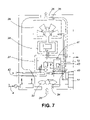
- FIG. 7 is a schematic for the basic flow diagram of the appliance showing the main controller, the motor controller and various sensors.
- FIG. 1 the home refueling appliance 1 is shown mounted on a garage wall with the high-pressure discharge hose 2 connected to a car, the inlet hose 3 connected to a source of gas, and the electrical cord 4 plugged into a standard household receptacle.
- FIG. 2 is a face view of the appliance in its housing 7 mounted between wall studs 5 with the front access cover 6 closed and the high pressure discharge hose 2 in the fully retracted position.
- the front access cover 6 is secured to the back panel of the housing 7 , shown in FIG. 6 , by hinges 8 .
- Air inlet vents 13 are located at the bottom of the front access cover 6 , beneath the motor/compressor assembly.
- a control and display panel 15 is located on the front access cover 6 , between the air inlet vents 13 .
- the housing mounting hardware consists of a lower mounting bracket 16 , helical springs 17 , an upper mounting bracket 19 , and polymeric isolators 20 shown in FIG. 3 b .
- the helical springs 17 and polymeric isolators 20 suppress the transmission of vibration, preferably those occurring below about 10 to 15 hertz, from the housing of the appliance through the mounting brackets 16 and 19 and into the wall studs 5 .
- a cowling 22 is attached to the back panel of the housing 7 by screws 23 .
- the back panel of the housing 7 and the cowling 22 form a ventilation enclosure for the compressor 29 , the compressor motor 30 , the blow-down volume 31 , the air motor/fan assembly 32 and ancillary components shown in FIG. 5 .
- the motor/fan assembly 32 draws cooling air through the intake duct 33 , past the air flow sensor 34 , and circulates the air over the air motor/fan assembly 32 , the casing 12 containing: blow-down volume 31 , compressor motor 30 , compressor 29 ; as well as other components within the enclosure formed by the back panel of the housing 7 and the cowling 22 .
- Air on leaving this ventilation enclosure passes by the flammable gas sensor 35 , shown in FIG. 6 , and out through the exhaust duct 36 . All sensors are connected to a central computer-circuit based main controller 11 .
- the central controller 11 ensures that the appliance 1 will not start up if it is already shut down; or will shut down if it is running.
- the motor/compressor assembly in casing 12 is secured to the back panel of the housing 7 by two polymeric mounts 37 , shown in FIG. 5 .
- the casing 12 is further connected to a polymeric damper 39 , shown in FIG. 6 .
- the mounts 37 are located about the approximate center of mass of the motor/compressor assembly, along a horizontal line that passes along a horizontal plane that passes approximately through such center of mass.
- the two polymeric mounts 37 and the polymeric damper 39 preferably suppress the transmission of vibrations of above about 10 to 15 hertz, and particularly vibrations of around 30 to 35 hertz, which occur over the normal operating range of the appliance, minimizing the transfer of such vibration from the motor/compressor assembly to the back panel of the housing 7 .
- a pressure sensor 40 connected to the low-pressure fuel gas inlet line 42 is connected electrically to the main controller 11 . If the pressure sensor 40 sends a signal to controller 11 that a gas pressure condition below a pre-set limit is being sensed, the controller 11 ensures that the appliance 1 will not start up if it is already shut down; or will shut it down if it is running.
- the motor controller circuitry 41 is located within the casing 12 , in the blow-down volume 31 .
- the wall of the casing 12 acts as heat sink for the heat produced by the motor controller circuitry 41 and as a shield for incoming and outgoing electromagnetic emissions.
- the main controller 11 is connected to receive signals from gas flow sensor 34 , flammable gas sensor 35 , source gas pressure sensor 4 as well as from the manual inputs on the control and display panel 15 and other sources such as the high pressure outlet gas sensor 43 .
- the main controller 11 is able to activate the motor 30 and govern its speed through motor controller 22 in accordance with the conditions previously described.
Landscapes
- Engineering & Computer Science (AREA)
- Mechanical Engineering (AREA)
- General Engineering & Computer Science (AREA)
- Chemical & Material Sciences (AREA)
- Combustion & Propulsion (AREA)
- Chemical Kinetics & Catalysis (AREA)
- General Chemical & Material Sciences (AREA)
- Oil, Petroleum & Natural Gas (AREA)
- Analytical Chemistry (AREA)
- Compressor (AREA)
- Filling Or Discharging Of Gas Storage Vessels (AREA)
- Structures Of Non-Positive Displacement Pumps (AREA)
- Drying Of Gases (AREA)
- Control Of Positive-Displacement Pumps (AREA)
- Vibration Prevention Devices (AREA)
- Air-Conditioning For Vehicles (AREA)
Priority Applications (25)
| Application Number | Priority Date | Filing Date | Title |
|---|---|---|---|
| US10/265,096 US7011118B2 (en) | 2002-10-04 | 2002-10-04 | Residential compressor for refueling motor vehicles that operate on gaseous fuels |
| BR0315043-7A BR0315043A (pt) | 2002-10-04 | 2003-10-06 | Compressor residencial para recompletarem veìculos motores que operam com combustìveis gasosos |
| AU2003271454A AU2003271454A1 (en) | 2002-10-04 | 2003-10-06 | Residential compressor for refueling motor vehicles that operate on gaseous fuels |
| JP2004540409A JP2006501416A (ja) | 2002-10-04 | 2003-10-06 | 気体燃料で作動する自動車に燃料補給するための住宅用圧縮器 |
| AU2003273657A AU2003273657A1 (en) | 2002-10-04 | 2003-10-06 | Gas compressor with drier |
| PCT/CA2003/001474 WO2004030794A2 (en) | 2002-10-04 | 2003-10-06 | Gas compressor with drier |
| CNB2003801049119A CN100400959C (zh) | 2002-10-04 | 2003-10-06 | 燃料添加装置及具有该装置的设备 |
| RU2005113867/06A RU2322637C2 (ru) | 2002-10-04 | 2003-10-06 | Бытовое устройство заправки автомобилей газообразным топливом (варианты) |
| CA2500915A CA2500915C (en) | 2002-10-04 | 2003-10-06 | Gas compressor with drier and radio emission controls |
| MXPA05003603A MXPA05003603A (es) | 2002-10-04 | 2003-10-06 | Compresor residencial para reabastecer vehiculos motrices que operan por combustibles gaseosos. |
| MXPA05003602A MXPA05003602A (es) | 2002-10-04 | 2003-10-06 | Compresor de gas con secador. |
| EP03757569A EP1558365A2 (de) | 2002-10-04 | 2003-10-06 | Gas kompressor mit trockner |
| JP2005500010A JP4499659B2 (ja) | 2002-10-04 | 2003-10-06 | 乾燥器を有する気体用の圧縮器 |
| ES03753163T ES2298554T3 (es) | 2002-10-04 | 2003-10-06 | Equipo domestico para repostar combustible destinado a repostar vehiculos de motor que funcionen con carburantes gaseosos. |
| DE60318083T DE60318083T2 (de) | 2002-10-04 | 2003-10-06 | Hauseigener kompressor zum betanken von gasbetriebenenen fahrzeugen |
| US10/530,310 US20060289080A1 (en) | 2002-10-04 | 2003-10-06 | Residential compressor for refueling motor vehicles that operate on gaseous fuels |
| RU2005113866/06A RU2336434C2 (ru) | 2002-10-04 | 2003-10-06 | Компрессорная система для сжатия газа |
| DK03753163T DK1549878T3 (da) | 2002-10-04 | 2003-10-06 | Hjemmekompressor til optankning af motorköretöjer, der drives af gasformige brændsler |
| CN2003801049142A CN1720090B (zh) | 2002-10-04 | 2003-10-06 | 压缩机设备 |
| EP03753163A EP1549878B1 (de) | 2002-10-04 | 2003-10-06 | Hauseigener kompressor zum betanken von gasbetriebenenen fahrzeugen |
| BRPI0315044-5A BR0315044B1 (pt) | 2002-10-04 | 2003-10-06 | sistema de compressão para gás. |
| US10/530,247 US8016570B2 (en) | 2002-10-04 | 2003-10-06 | Gas compressor with drier and radio emission controls |
| AT03753163T ATE380968T1 (de) | 2002-10-04 | 2003-10-06 | Hauseigener kompressor zum betanken von gasbetriebenenen fahrzeugen |
| CA002500989A CA2500989A1 (en) | 2002-10-04 | 2003-10-06 | Residential compressor for refueling motor vehicles that operate on gaseous fuels |
| PCT/CA2003/001475 WO2004031643A1 (en) | 2002-10-04 | 2003-10-06 | Residential compressor for refueling motor vehicles that operate on gaseous fuels |
Applications Claiming Priority (1)
| Application Number | Priority Date | Filing Date | Title |
|---|---|---|---|
| US10/265,096 US7011118B2 (en) | 2002-10-04 | 2002-10-04 | Residential compressor for refueling motor vehicles that operate on gaseous fuels |
Related Child Applications (2)
| Application Number | Title | Priority Date | Filing Date |
|---|---|---|---|
| US11/530,310 Continuation US7800812B2 (en) | 2005-09-08 | 2006-09-08 | Intelligent SPD control apparatus with scalable networking capabilities for window and multimedia applications |
| US10530247 Continuation-In-Part | 2007-05-07 |
Publications (2)
| Publication Number | Publication Date |
|---|---|
| US20040065676A1 US20040065676A1 (en) | 2004-04-08 |
| US7011118B2 true US7011118B2 (en) | 2006-03-14 |
Family
ID=32042401
Family Applications (2)
| Application Number | Title | Priority Date | Filing Date |
|---|---|---|---|
| US10/265,096 Expired - Fee Related US7011118B2 (en) | 2002-10-04 | 2002-10-04 | Residential compressor for refueling motor vehicles that operate on gaseous fuels |
| US10/530,310 Abandoned US20060289080A1 (en) | 2002-10-04 | 2003-10-06 | Residential compressor for refueling motor vehicles that operate on gaseous fuels |
Family Applications After (1)
| Application Number | Title | Priority Date | Filing Date |
|---|---|---|---|
| US10/530,310 Abandoned US20060289080A1 (en) | 2002-10-04 | 2003-10-06 | Residential compressor for refueling motor vehicles that operate on gaseous fuels |
Country Status (14)
| Country | Link |
|---|---|
| US (2) | US7011118B2 (de) |
| EP (1) | EP1549878B1 (de) |
| JP (1) | JP2006501416A (de) |
| CN (2) | CN100400959C (de) |
| AT (1) | ATE380968T1 (de) |
| AU (1) | AU2003271454A1 (de) |
| BR (1) | BR0315043A (de) |
| CA (1) | CA2500989A1 (de) |
| DE (1) | DE60318083T2 (de) |
| DK (1) | DK1549878T3 (de) |
| ES (1) | ES2298554T3 (de) |
| MX (1) | MXPA05003603A (de) |
| RU (1) | RU2322637C2 (de) |
| WO (1) | WO2004031643A1 (de) |
Cited By (7)
| Publication number | Priority date | Publication date | Assignee | Title |
|---|---|---|---|---|
| US20060162811A1 (en) * | 2003-06-11 | 2006-07-27 | John Roach | Liquefied gas storage installation |
| WO2011115522A1 (ru) * | 2010-03-15 | 2011-09-22 | КИСЕЛЕВ, Александр Михайлович | Модуль нагрузочный испытательный резистивный (балластный) |
| US20140182561A1 (en) * | 2013-09-25 | 2014-07-03 | Eghosa Gregory Ibizugbe, JR. | Onboard CNG/CFG Vehicle Refueling and Storage Systems and Methods |
| US20140216596A1 (en) * | 2012-02-07 | 2014-08-07 | Paul R. Juhasz | Vehicle Fuel Dispensing System for Dwellings |
| US9279420B2 (en) | 2013-05-31 | 2016-03-08 | Intellectual Property Holdings, Llc | Natural gas compressor |
| US9618158B2 (en) | 2011-05-02 | 2017-04-11 | New Gas Industries, L.L.C. | Method and apparatus for compressing gas in a plurality of stages to a storage tank array having a plurality of storage tanks |
| US10551001B2 (en) | 2015-09-03 | 2020-02-04 | J-W Power Company | Flow control system |
Families Citing this family (12)
| Publication number | Priority date | Publication date | Assignee | Title |
|---|---|---|---|---|
| US7892304B2 (en) * | 2004-12-17 | 2011-02-22 | Texaco Inc. | Apparatus and method for controlling compressor motor speed in a hydrogen generator |
| US7763087B2 (en) * | 2004-12-17 | 2010-07-27 | Texaco Inc. | Safety system architecture for a hydrogen fueling station |
| GB2435311B (en) | 2006-02-16 | 2011-01-19 | Gasfill Ltd | Fluid compressor and motor vehicle refuelling apparatus |
| DE102014000639A1 (de) | 2013-01-18 | 2014-07-24 | Michael Feldmann | Verfahren und Anlagen für eine Gastankstelle zur größenoptimierten Abgabe gasförmiger Gaskraftstoffe an mobile Verbraucher |
| EP2908044A3 (de) | 2014-01-17 | 2015-09-09 | Michael Feldmann | Verfahren und Anlagen für eine Gastankstelle zur größenoptimierten Abgabe gasförmiger Gaskraftstoffe an mobile Verbraucher |
| EP2899449A3 (de) * | 2014-01-20 | 2015-09-02 | Michael Feldmann | Verfahren und Anlagenkonfiguration zum dynamisierten Aufbau einer Gastankstellen-Infrastruktur |
| RU178332U1 (ru) * | 2017-04-26 | 2018-03-30 | Федеральное государственное бюджетное образовательное учреждение высшего образования "Рязанский государственный агротехнологический университет имени П.А. Костычева" (ФГБОУ ВО РГАТУ) | Топливная система газового двигателя внутреннего сгорания |
| WO2020109846A1 (ru) * | 2018-11-29 | 2020-06-04 | Хайджен, Сиа | Устройство для обеспечения безопасности заправки транспортного средства компрессированным газовым топливом легче воздуха и способ заправки транспортного средства |
| DE102020201046A1 (de) | 2020-01-29 | 2021-07-29 | Robert Bosch Gesellschaft mit beschränkter Haftung | Druckgasspeicheraufnahmevorrichtung für ein Kraftfahrzeug, System mit einem Kraftfahrzeug und einer Kühlungsvorrichtung, Tankstelle für ein solches System sowie Verfahren zum Betanken eines Kraftfahrzeuges |
| RU205185U1 (ru) * | 2021-04-21 | 2021-06-30 | Общество С Ограниченной Ответственностью "Газовые Компрессорные Системы" | Индивидуальное устройство для заправки автомобильного транспорта |
| US11813916B2 (en) * | 2021-10-14 | 2023-11-14 | Beijingwest Industries Co., Ltd. | Integrated air supply unit |
| EP4198374B1 (de) * | 2021-12-20 | 2025-06-11 | Volvo Construction Equipment AB | Mobiles fluidzuführungssystem, verfahren zur zuführung von fluid, steuerungseinheit und fahrzeug, schiff oder wasserfahrzeug mit dem mobilen fluidzuführungssystem |
Citations (16)
| Publication number | Priority date | Publication date | Assignee | Title |
|---|---|---|---|---|
| US3799218A (en) * | 1972-03-27 | 1974-03-26 | M Douglass | Apparatus for dispensing compressed gas at programmed pressure and volume |
| US4501253A (en) | 1982-12-13 | 1985-02-26 | Consolidated Natural Gas Service Company, Inc. | On-board automotive methane compressor |
| US4531558A (en) * | 1983-04-13 | 1985-07-30 | Michigan Consolidated Gas Co. | Gaseous fuel refueling apparatus |
| US4624390A (en) | 1984-03-29 | 1986-11-25 | Dual Fuel Systems, Inc. | Natural gas fueling system |
| US4966206A (en) | 1987-07-23 | 1990-10-30 | Sulzer Brothers Limited | Device for filling a gaseous fuel container |
| CH676951A5 (en) | 1988-08-12 | 1991-03-28 | Sulzer Ag | Vehicle gas tank filling appliance - has second internal housing for compressor-motor group |
| US5029622A (en) | 1988-08-15 | 1991-07-09 | Sulzer Brothers Limited | Gas refuelling device and method of refuelling a motor vehicle |
| US5263826A (en) | 1991-05-30 | 1993-11-23 | Sulzer Brothers Limited | Device for refueling a gaseous fuel tank |
| US5370159A (en) | 1993-07-19 | 1994-12-06 | Price Compressor Company, Inc. | Apparatus and process for fast filling with natural gas |
| US5501200A (en) | 1994-06-28 | 1996-03-26 | Bogartz; Stuart P. | Compressed gas fueling system |
| US5653269A (en) | 1991-06-27 | 1997-08-05 | Miller; Charles E. | Method and apparatus for multiple-channel dispensing of natural gas |
| EP0799635A1 (de) | 1996-04-02 | 1997-10-08 | Atlas Copco Airpower N.V. | Verfahren und Vorrichtung zum Trocknen eines komprimierten Gases |
| DE19859423C1 (de) | 1998-12-22 | 2000-04-20 | Hermann Heinz Burger Gas Und W | Vorrichtung zum Betanken von Fahrzeugen mit Erdgas |
| US6117211A (en) | 1994-02-21 | 2000-09-12 | Fuelmaker Corporation | Gas desiccation and contaminant disposal method and apparatus |
| WO2001078872A2 (en) | 2000-04-13 | 2001-10-25 | Atlas Copco Airpower, Naamloze Vennootschap | Compressor installation provided with a drying device |
| US6360793B1 (en) * | 1999-02-08 | 2002-03-26 | Yamaha Hatsudoki Kabushiki Kaisha | Fast fill method and apparatus |
Family Cites Families (7)
| Publication number | Priority date | Publication date | Assignee | Title |
|---|---|---|---|---|
| JPH0347478U (de) * | 1989-09-13 | 1991-05-02 | ||
| SU1809164A1 (en) * | 1990-12-17 | 1993-04-15 | Vsesoyuznyj Ni I Kt I Kompress | Vehicle gas supply compressor plant |
| US5221192A (en) * | 1992-07-16 | 1993-06-22 | Carrier Corporation | Elastomeric compressor stud mount |
| JPH06288353A (ja) * | 1993-04-02 | 1994-10-11 | Mitsubishi Heavy Ind Ltd | 横置形圧縮機の防振支持装置 |
| JPH09196295A (ja) * | 1996-01-19 | 1997-07-29 | Tokico Ltd | ガス供給装置 |
| RU11586U1 (ru) * | 1998-02-18 | 1999-10-16 | Всероссийский научно-исследовательский институт природных газов и газовых технологий, Российское акционерное общество "Газпром" | Передвижная газонаполнительная установка |
| DE19933791A1 (de) * | 1999-07-20 | 2001-02-01 | Linde Gas Ag | Verfahren und Tankstelle zum Betanken eines Fahrzeugtanks mit einem gasförmigen Treibstoff |
-
2002
- 2002-10-04 US US10/265,096 patent/US7011118B2/en not_active Expired - Fee Related
-
2003
- 2003-10-06 AU AU2003271454A patent/AU2003271454A1/en not_active Abandoned
- 2003-10-06 RU RU2005113867/06A patent/RU2322637C2/ru not_active IP Right Cessation
- 2003-10-06 ES ES03753163T patent/ES2298554T3/es not_active Expired - Lifetime
- 2003-10-06 DK DK03753163T patent/DK1549878T3/da active
- 2003-10-06 DE DE60318083T patent/DE60318083T2/de not_active Expired - Lifetime
- 2003-10-06 WO PCT/CA2003/001475 patent/WO2004031643A1/en not_active Ceased
- 2003-10-06 CN CNB2003801049119A patent/CN100400959C/zh not_active Expired - Fee Related
- 2003-10-06 JP JP2004540409A patent/JP2006501416A/ja active Pending
- 2003-10-06 EP EP03753163A patent/EP1549878B1/de not_active Expired - Lifetime
- 2003-10-06 CN CN2003801049142A patent/CN1720090B/zh not_active Expired - Fee Related
- 2003-10-06 MX MXPA05003603A patent/MXPA05003603A/es active IP Right Grant
- 2003-10-06 BR BR0315043-7A patent/BR0315043A/pt active Search and Examination
- 2003-10-06 US US10/530,310 patent/US20060289080A1/en not_active Abandoned
- 2003-10-06 AT AT03753163T patent/ATE380968T1/de active
- 2003-10-06 CA CA002500989A patent/CA2500989A1/en not_active Abandoned
Patent Citations (16)
| Publication number | Priority date | Publication date | Assignee | Title |
|---|---|---|---|---|
| US3799218A (en) * | 1972-03-27 | 1974-03-26 | M Douglass | Apparatus for dispensing compressed gas at programmed pressure and volume |
| US4501253A (en) | 1982-12-13 | 1985-02-26 | Consolidated Natural Gas Service Company, Inc. | On-board automotive methane compressor |
| US4531558A (en) * | 1983-04-13 | 1985-07-30 | Michigan Consolidated Gas Co. | Gaseous fuel refueling apparatus |
| US4624390A (en) | 1984-03-29 | 1986-11-25 | Dual Fuel Systems, Inc. | Natural gas fueling system |
| US4966206A (en) | 1987-07-23 | 1990-10-30 | Sulzer Brothers Limited | Device for filling a gaseous fuel container |
| CH676951A5 (en) | 1988-08-12 | 1991-03-28 | Sulzer Ag | Vehicle gas tank filling appliance - has second internal housing for compressor-motor group |
| US5029622A (en) | 1988-08-15 | 1991-07-09 | Sulzer Brothers Limited | Gas refuelling device and method of refuelling a motor vehicle |
| US5263826A (en) | 1991-05-30 | 1993-11-23 | Sulzer Brothers Limited | Device for refueling a gaseous fuel tank |
| US5653269A (en) | 1991-06-27 | 1997-08-05 | Miller; Charles E. | Method and apparatus for multiple-channel dispensing of natural gas |
| US5370159A (en) | 1993-07-19 | 1994-12-06 | Price Compressor Company, Inc. | Apparatus and process for fast filling with natural gas |
| US6117211A (en) | 1994-02-21 | 2000-09-12 | Fuelmaker Corporation | Gas desiccation and contaminant disposal method and apparatus |
| US5501200A (en) | 1994-06-28 | 1996-03-26 | Bogartz; Stuart P. | Compressed gas fueling system |
| EP0799635A1 (de) | 1996-04-02 | 1997-10-08 | Atlas Copco Airpower N.V. | Verfahren und Vorrichtung zum Trocknen eines komprimierten Gases |
| DE19859423C1 (de) | 1998-12-22 | 2000-04-20 | Hermann Heinz Burger Gas Und W | Vorrichtung zum Betanken von Fahrzeugen mit Erdgas |
| US6360793B1 (en) * | 1999-02-08 | 2002-03-26 | Yamaha Hatsudoki Kabushiki Kaisha | Fast fill method and apparatus |
| WO2001078872A2 (en) | 2000-04-13 | 2001-10-25 | Atlas Copco Airpower, Naamloze Vennootschap | Compressor installation provided with a drying device |
Cited By (9)
| Publication number | Priority date | Publication date | Assignee | Title |
|---|---|---|---|---|
| US20060162811A1 (en) * | 2003-06-11 | 2006-07-27 | John Roach | Liquefied gas storage installation |
| WO2011115522A1 (ru) * | 2010-03-15 | 2011-09-22 | КИСЕЛЕВ, Александр Михайлович | Модуль нагрузочный испытательный резистивный (балластный) |
| US9618158B2 (en) | 2011-05-02 | 2017-04-11 | New Gas Industries, L.L.C. | Method and apparatus for compressing gas in a plurality of stages to a storage tank array having a plurality of storage tanks |
| US10465850B2 (en) | 2011-05-02 | 2019-11-05 | New Gas Industries, L.L.C. | Method and apparatus for compressing gas in a plurality of stages to a storage tank array having a plurality of storage tanks |
| US20140216596A1 (en) * | 2012-02-07 | 2014-08-07 | Paul R. Juhasz | Vehicle Fuel Dispensing System for Dwellings |
| US9296602B2 (en) * | 2012-02-07 | 2016-03-29 | Paul R. Juhasz | Vehicle fuel dispensing system for dwellings |
| US9279420B2 (en) | 2013-05-31 | 2016-03-08 | Intellectual Property Holdings, Llc | Natural gas compressor |
| US20140182561A1 (en) * | 2013-09-25 | 2014-07-03 | Eghosa Gregory Ibizugbe, JR. | Onboard CNG/CFG Vehicle Refueling and Storage Systems and Methods |
| US10551001B2 (en) | 2015-09-03 | 2020-02-04 | J-W Power Company | Flow control system |
Also Published As
| Publication number | Publication date |
|---|---|
| CN1720090B (zh) | 2010-04-28 |
| CN1720090A (zh) | 2006-01-11 |
| US20060289080A1 (en) | 2006-12-28 |
| DE60318083T2 (de) | 2008-11-20 |
| ES2298554T3 (es) | 2008-05-16 |
| AU2003271454A1 (en) | 2004-04-23 |
| WO2004031643A1 (en) | 2004-04-15 |
| CA2500989A1 (en) | 2004-04-15 |
| DE60318083D1 (de) | 2008-01-24 |
| DK1549878T3 (da) | 2008-05-05 |
| EP1549878A1 (de) | 2005-07-06 |
| RU2322637C2 (ru) | 2008-04-20 |
| MXPA05003603A (es) | 2006-04-05 |
| JP2006501416A (ja) | 2006-01-12 |
| ATE380968T1 (de) | 2007-12-15 |
| CN100400959C (zh) | 2008-07-09 |
| CN1720412A (zh) | 2006-01-11 |
| BR0315043A (pt) | 2005-08-23 |
| EP1549878B1 (de) | 2007-12-12 |
| US20040065676A1 (en) | 2004-04-08 |
| RU2005113867A (ru) | 2005-10-10 |
Similar Documents
| Publication | Publication Date | Title |
|---|---|---|
| US7011118B2 (en) | Residential compressor for refueling motor vehicles that operate on gaseous fuels | |
| US11971070B2 (en) | Indoor unit for an air conditioner | |
| RU2644737C2 (ru) | Разработки, касающиеся моющих/сушащих станций в туалетных комнатах | |
| KR20200095140A (ko) | 소리 입력이 가능한 냉장고 | |
| US9871411B2 (en) | HVAC home generator | |
| JPWO2018167928A1 (ja) | ヒートポンプ装置 | |
| CN210123693U (zh) | 一种油浸式变压器 | |
| JP2014031902A (ja) | ヒートポンプ給湯室外機 | |
| CN220119482U (zh) | 一种便携式空调器 | |
| CN215633687U (zh) | 一种送水泵房智能调压装置 | |
| CN114017805B (zh) | 一种烟灶组件 | |
| GB2211028A (en) | Resilient mounting in a standby generator system | |
| JP6635202B2 (ja) | ヒートポンプ装置 | |
| CN222257200U (zh) | 储能空调 | |
| CN207674586U (zh) | 空调室内机 | |
| CN201807480U (zh) | 一种集成式人工造雾用主机组 | |
| CN222760998U (zh) | 集成烹饪设备 | |
| CN219346729U (zh) | 水箱组件和冷风扇 | |
| CN220582568U (zh) | 一种热泵式空调室外机及空调 | |
| CN2238394Y (zh) | 一种窗式空调器 | |
| CN220624225U (zh) | 一种空调室内机 | |
| CN218943134U (zh) | 一种食品加工机 | |
| CN113280439B (zh) | 一种通风设备及通风系统 | |
| CN112984793B (zh) | 用于吊挂安装的热泵机组及热泵热水器 | |
| JPH07133893A (ja) | 天然ガス充填装置 |
Legal Events
| Date | Code | Title | Description |
|---|---|---|---|
| AS | Assignment |
Owner name: FUELMAKER CORPORATION, CANADA Free format text: ASSIGNMENT OF ASSIGNORS INTEREST;ASSIGNORS:CHAN, ANTHONY WAI PANG;ATANASSOV, FILIP;RACKHAM, RALPH;AND OTHERS;REEL/FRAME:017019/0154;SIGNING DATES FROM 20040623 TO 20040717 |
|
| AS | Assignment |
Owner name: 2045951 ONTARIO INC., CANADA Free format text: ASSIGNMENT OF ASSIGNORS INTEREST;ASSIGNOR:FUELMAKER CORPORATION;REEL/FRAME:017151/0412 Effective date: 20051116 |
|
| CC | Certificate of correction | ||
| FPAY | Fee payment |
Year of fee payment: 4 |
|
| AS | Assignment |
Owner name: MTM S.R.L., ITALY Free format text: ASSIGNMENT OF ASSIGNORS INTEREST;ASSIGNOR:2045951 ONTARIO INC.;REEL/FRAME:023627/0031 Effective date: 20090522 |
|
| FPAY | Fee payment |
Year of fee payment: 8 |
|
| FEPP | Fee payment procedure |
Free format text: MAINTENANCE FEE REMINDER MAILED (ORIGINAL EVENT CODE: REM.) |
|
| LAPS | Lapse for failure to pay maintenance fees |
Free format text: PATENT EXPIRED FOR FAILURE TO PAY MAINTENANCE FEES (ORIGINAL EVENT CODE: EXP.) |
|
| STCH | Information on status: patent discontinuation |
Free format text: PATENT EXPIRED DUE TO NONPAYMENT OF MAINTENANCE FEES UNDER 37 CFR 1.362 |
|
| FP | Lapsed due to failure to pay maintenance fee |
Effective date: 20180314 |