US695453A - Hinge. - Google Patents
Hinge. Download PDFInfo
- Publication number
- US695453A US695453A US4184201A US1901041842A US695453A US 695453 A US695453 A US 695453A US 4184201 A US4184201 A US 4184201A US 1901041842 A US1901041842 A US 1901041842A US 695453 A US695453 A US 695453A
- Authority
- US
- United States
- Prior art keywords
- hinge
- blank
- angular
- offset portion
- pintle
- Prior art date
- Legal status (The legal status is an assumption and is not a legal conclusion. Google has not performed a legal analysis and makes no representation as to the accuracy of the status listed.)
- Expired - Lifetime
Links
Images
Classifications
-
- E—FIXED CONSTRUCTIONS
- E05—LOCKS; KEYS; WINDOW OR DOOR FITTINGS; SAFES
- E05F—DEVICES FOR MOVING WINGS INTO OPEN OR CLOSED POSITION; CHECKS FOR WINGS; WING FITTINGS NOT OTHERWISE PROVIDED FOR, CONCERNED WITH THE FUNCTIONING OF THE WING
- E05F1/00—Closers or openers for wings, not otherwise provided for in this subclass
- E05F1/02—Closers or openers for wings, not otherwise provided for in this subclass gravity-actuated, e.g. by use of counterweights
- E05F1/04—Closers or openers for wings, not otherwise provided for in this subclass gravity-actuated, e.g. by use of counterweights for wings which lift during movement, operated by their own weight
- E05F1/06—Mechanisms in the shape of hinges or pivots, operated by the weight of the wing
- E05F1/061—Mechanisms in the shape of hinges or pivots, operated by the weight of the wing with cams or helical tracks
- E05F1/063—Mechanisms in the shape of hinges or pivots, operated by the weight of the wing with cams or helical tracks with complementary, substantially identical and slidingly cooperating cam surfaces
Definitions
- W nvaspsaszm NORRIS Parana ca. PHOTD LITNO., wxsmuawmn. c.
- My invention relates to improvements in hinges; and it. consists in the novel features of construction hereinafter described, reference being had to the accompanying drawin gs, which illustrate one form in which Ihave contemplated embodying my invention; and said invention is fully disclosed in the following description and claim.
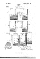
- Figure 1 shows the blanks for the-two, leaves of the hinge which have been stamped out of a single piece of metal.
- Fig. 2 represents the two leaves of the hinge with the offset portions of the blanks bent around as in thefinished hinge. It also represents one of'said portions as having the pintle secured within the hollow cylindrical opening formedby said race d is applied to the edge of each of the portion.
- Fig. 3 represents the two members of the hinge placed together in closed position.
- Fig. 4 shows a modification wherein ball-bearings are applied to the inclined portions of the knuckles, and Fig. 5-showstl1e hinge in open position.
- a andB represent blanks for the two leaves of the hinge.
- Each blank consistsof the main rectangular body provided with an offset portion having an angular extension.
- the angular extension of blank A is designated by reference-letter a, and between the same and the main body of the blank and the extension o is a straight surface, forming the shoulder a.
- the angular extension'of the blank B is designated by the reference-letter b, and its end is provided with the short straight surface 1), corresponding in extent to the shoulder a.
- the construction of the two blanks is such that'they may be stamped or cut out of a single rectangular piece of ;ters Patent, is-- sheet metal without'any waste of material or which may be cut from a larger piece of sheet metal equally without waste.
- the angular projection of the blank A will fit between the angular projection 17 of the blank B, and'it' will'alsobe seen that the offset portion of one leaf corresponds with the cut-away portions of the other leaf.
- the blank A having the shoulder a is preferably used as the lower leaf of the hinge, and the offset portion of the same is'bent around upon the pintle C, so as to hold the same securely in place.
- the offset portion of the blank] is bent to form a hollow cylindrical part to engage and turn freely upon the pintle O.
- the two parts of the hinge are so constructed as to form a complete hinge andat-the same time it will be apparent that when the hinge is opened and the part B turned upon the pintle the engaging angular edges will cause'the'part B to rise on the pintle C, so that when the hinge is applied to a doorwhenever the door is opened the- Weight of the samelwill tend to close it," which itwill do as soon as released and the'same is free to move.
Description
No. 695,453. MM Man; I8, I902.
R. FRANK. I
HINGE.
(Application filed. Jan. 2, 1901,). (No Model.)
INVENTOR; W nvaspsaszm: NORRIS Parana ca. PHOTD LITNO., wxsmuawmn. c.
UNITED mm 'ATENT FFICE.
ROSE FRANK, OF PASADENA, CALIFORNIA, ASSIGNOR TO JACQUES FRANC,
' OF PASADENA, CALIFORNIA.-
HINGE.
SPECIFICATION forming part of Letters Patent No. 695,453, dated March 18, 1902.
Applicatiouliled January 2, 1901. Serial No. 41,842. (No model.)
To aZZ whom it may concern:
Be it known that L'Rosn FRANK, a citizen of the United States, residing at Pasadena,
in the county of Los Angeles and State of.
California, have invented certain new and useful Improvements in Hinges; and I do hereby declare the followingto be a full, clear,
and exact description of the invention, such as will enableot-hers skilled in the art to which;
it appertaius to make and use the same.
My invention relates to improvements in hinges; and it. consists in the novel features of construction hereinafter described, reference being had to the accompanying drawin gs, which illustrate one form in which Ihave contemplated embodying my invention; and said invention is fully disclosed in the following description and claim.
Referring to the drawings, Figure 1 shows the blanks for the-two, leaves of the hinge which have been stamped out of a single piece of metal. Fig. 2 represents the two leaves of the hinge with the offset portions of the blanks bent around as in thefinished hinge. It also represents one of'said portions as having the pintle secured within the hollow cylindrical opening formedby said race d is applied to the edge of each of the portion. Fig. 3 represents the two members of the hinge placed together in closed position. Fig. 4 shows a modification wherein ball-bearings are applied to the inclined portions of the knuckles, and Fig. 5-showstl1e hinge in open position.
A andB represent blanks for the two leaves of the hinge. Each blank consistsof the main rectangular body provided with an offset portion having an angular extension. The angular extension of blank A is designated by reference-letter a, and between the same and the main body of the blank and the extension o is a straight surface, forming the shoulder a. The angular extension'of the blank B is designated by the reference-letter b, and its end is provided with the short straight surface 1), corresponding in extent to the shoulder a. The construction of the two blanks is such that'they may be stamped or cut out of a single rectangular piece of ;ters Patent, is-- sheet metal without'any waste of material or which may be cut from a larger piece of sheet metal equally without waste. It will be seen that the angular projection of the blank A will fit between the angular projection 17 of the blank B, and'it' will'alsobe seen that the offset portion of one leaf corresponds with the cut-away portions of the other leaf. The blank A having the shoulder a is preferably used as the lower leaf of the hinge, and the offset portion of the same is'bent around upon the pintle C, so as to hold the same securely in place. The offset portion of the blank]; is bent to form a hollow cylindrical part to engage and turn freely upon the pintle O. By this construction the two parts of the hinge are so constructed as to form a complete hinge andat-the same time it will be apparent that when the hinge is opened and the part B turned upon the pintle the engaging angular edges will cause'the'part B to rise on the pintle C, so that when the hinge is applied to a doorwhenever the door is opened the- Weight of the samelwill tend to close it," which itwill do as soon as released and the'same is free to move.
In the modification shown in Fig. 4 a ballcams for receiving ball-bearings d, which will decrease the friction at that point.
What I claim, and
desire to secure by Let'- i A hinge, the two leaves of which are adapted to be cut from a single piece of metal with out any Waste of material, each of said leaves being provided with an offset portion and an angular projection on said oifsetportion, said offset portion and said'angular projection being adapted to be bent toform the knuckle, "andsaid ofisetportion and angular projection I .of one leaf correspondingto the cut-away pornon of theother, substantially as described.
In testimony whereof I affix my signature in the presence of two witnesses.
ROSE FRANK;
Witnesses:
SAML. I. HEPNER, CARRIE F. ADLER.
Priority Applications (1)
| Application Number | Priority Date | Filing Date | Title |
|---|---|---|---|
| US4184201A US695453A (en) | 1901-01-02 | 1901-01-02 | Hinge. |
Applications Claiming Priority (1)
| Application Number | Priority Date | Filing Date | Title |
|---|---|---|---|
| US4184201A US695453A (en) | 1901-01-02 | 1901-01-02 | Hinge. |
Publications (1)
| Publication Number | Publication Date |
|---|---|
| US695453A true US695453A (en) | 1902-03-18 |
Family
ID=2763989
Family Applications (1)
| Application Number | Title | Priority Date | Filing Date |
|---|---|---|---|
| US4184201A Expired - Lifetime US695453A (en) | 1901-01-02 | 1901-01-02 | Hinge. |
Country Status (1)
| Country | Link |
|---|---|
| US (1) | US695453A (en) |
-
1901
- 1901-01-02 US US4184201A patent/US695453A/en not_active Expired - Lifetime
Similar Documents
| Publication | Publication Date | Title |
|---|---|---|
| US769035A (en) | Lock-hinge. | |
| US770595A (en) | Hinge | |
| US695453A (en) | Hinge. | |
| US809137A (en) | Flush hinge. | |
| US426597A (en) | Spring-hinge | |
| US929615A (en) | Hinge. | |
| US378861A (en) | Hinge | |
| US393305A (en) | Louis hillebeand | |
| US1113278A (en) | Interlocking hinge. | |
| US586146A (en) | Adolph steinfeldt | |
| US1045851A (en) | Hinge. | |
| US919150A (en) | Blind-hinge. | |
| US951327A (en) | Hinge. | |
| US529312A (en) | Alberta eiley | |
| US460589A (en) | Hinge | |
| US1037807A (en) | Hinge. | |
| US918135A (en) | Hinge. | |
| US1012162A (en) | Hinge. | |
| US755211A (en) | Hinge. | |
| US808138A (en) | Hinge. | |
| US858091A (en) | Latch. | |
| US1058944A (en) | Gravity-hinge. | |
| US809027A (en) | Hinge. | |
| US1271235A (en) | Butt-hinge. | |
| US905834A (en) | Hinge. |