US683046A - Incandescent-lamp protector. - Google Patents
Incandescent-lamp protector. Download PDFInfo
- Publication number
- US683046A US683046A US6531701A US1901065317A US683046A US 683046 A US683046 A US 683046A US 6531701 A US6531701 A US 6531701A US 1901065317 A US1901065317 A US 1901065317A US 683046 A US683046 A US 683046A
- Authority
- US
- United States
- Prior art keywords
- lamp
- diaphragm
- bulb
- incandescent
- protector
- Prior art date
- Legal status (The legal status is an assumption and is not a legal conclusion. Google has not performed a legal analysis and makes no representation as to the accuracy of the status listed.)
- Expired - Lifetime
Links
- 230000001012 protector Effects 0.000 title description 27
- 210000000188 diaphragm Anatomy 0.000 description 41
- 239000000463 material Substances 0.000 description 6
- 238000010276 construction Methods 0.000 description 4
- XLYOFNOQVPJJNP-UHFFFAOYSA-N water Substances O XLYOFNOQVPJJNP-UHFFFAOYSA-N 0.000 description 3
- 238000005286 illumination Methods 0.000 description 2
- 230000004048 modification Effects 0.000 description 2
- 238000012986 modification Methods 0.000 description 2
- 239000000126 substance Substances 0.000 description 2
- 208000027418 Wounds and injury Diseases 0.000 description 1
- 230000006978 adaptation Effects 0.000 description 1
- 230000015572 biosynthetic process Effects 0.000 description 1
- 239000012141 concentrate Substances 0.000 description 1
- 230000006378 damage Effects 0.000 description 1
- 238000005034 decoration Methods 0.000 description 1
- 230000000694 effects Effects 0.000 description 1
- 230000005484 gravity Effects 0.000 description 1
- 208000014674 injury Diseases 0.000 description 1
- 238000003780 insertion Methods 0.000 description 1
- 230000037431 insertion Effects 0.000 description 1
- 238000012423 maintenance Methods 0.000 description 1
- 238000004519 manufacturing process Methods 0.000 description 1
- 238000007142 ring opening reaction Methods 0.000 description 1
- 238000006467 substitution reaction Methods 0.000 description 1
Images
Classifications
-
- F—MECHANICAL ENGINEERING; LIGHTING; HEATING; WEAPONS; BLASTING
- F21—LIGHTING
- F21V—FUNCTIONAL FEATURES OR DETAILS OF LIGHTING DEVICES OR SYSTEMS THEREOF; STRUCTURAL COMBINATIONS OF LIGHTING DEVICES WITH OTHER ARTICLES, NOT OTHERWISE PROVIDED FOR
- F21V15/00—Protecting lighting devices from damage
- F21V15/02—Cages
Definitions
- This invention relates to incandescentlamp protectors; and it has for its object to provide an improved protector of this class whereby the bases or sockets of incandescent lamps exposed to the elements may be effectually protected against short-circuiting and other injury customarily occasioned by the attack of rain-water and other extraneous and harmful material or objects.
- the invention is particularly adapted for the protection of incandescent electric lamps employed in the illumination of outdoor display-signsembodying words or letters, but may be conveniently and effectively applied for the protection of incandescent lamps otherwise installed-as, for instance, in cornice and facade decoration and illumination.
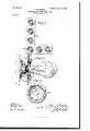
- Figure 1 is a front elevation of an illuminated sign-letter embodying incandescent-lamp bulbs provided with my improved protectors, the bulbs being transversely sectioned.
- Fig. 2 is a detail vertical sectional view taken through one of the bulbs and the protector of the same.
- Fig. 3 is a rear orbottom plan view of the improved protector in detached position.
- 1 designates my improved protector, which embodies a flexible and preferably elastic diaphragm 2, which is provided with a central opening or perforation 3, through which the neck 4 of the incandescent-lamp bulb 5 is passed for connection with the lamp-socket 6.
- the flexible diaphragm 2 is carried byabody-ring 7, which is fitted into the lamp-fitting 8, which in the present instance consists of the face-plate 9 of an illuminated letter 10, which is provided with an opening 12 to receive the body-ring 7 and the neck 4 of the bulb.
- the socket 6 beneath the face-plate 9 of the sign-letter 10 is thus effectually housed and protected against all influences which would tend to interfere with the maintenance of a perfect circuit or condition of the line-wire, switch, contacts, and other features comprised in the socket construction.
- the concavity of the diaphragm 2 caused by the dishing of the same in the insertion of the neck of the bulb through the opening 3, causes the discharge from said diaphragm of any water or other mobile substances which might flow onto the outer surface 13 of the same, such substance being discharged from the diaphragm by gravity.
- the outer or forward surface portion 13 of the diaphragm 2 may be decorated or colored as desired; but to increase or concentrate the illuminating power of the lamp the said outer surface portion 13 is preferably of a pure white color, the result being that the rays of light cast by the bulb from end to end are pure white in color and give the highest illuminating effect.
- the protector embodies in a single entirety the body-ring 7, the diaphragm 2, and a rearwardly-projecting securing-flange 14, between which and the rear surface of the bodyring 7 the face-plate 9 of the letter or the corresponding part of the lampfitting of other design is received.
- the entire pro tector may be inexpensively molded out of soft rubber, which will provide for the elastic quality of the diaphragm 2 and will cause the body-ring 7 and the securing-flange 1 4 to bind firmly upon the face-plate 9 or other lamp-fitting.
- the securing-flange 14 extends continuously around the inner edge portion of the body-ring 7 at the inner or rear face of the same, and the forward wall of the same is formed with a rearward flare or bevel, as at 15, the rear or inner face of the body-ring 7 being correspondingly rearwardly flared or beveled, as at 16.
- the flared or beveled surface portions 15 and 16 cause a more positive and tight joint or connection of the protector with the face-plate 9 or other lamp-fitting, effectually preventing the entrance of moisture or other extraneous materials between the edge portions of the opening 12 in the face-plate 9 and the Walls of the body-ring 7 and securing-flange 14.
- the securing-flange 14 is simply forced through said opening 12 until the edge portions of said opening 12 are firmly seated between the securing-flange and the body-ring, the inner or rear surface portion 16of the body-ring fitting tightly against the portions of the face-plate 9 which surround the opening 12.
- the protector 1 is thus firmly secured in operative position, but may be removed for repair or substitution by simply withdrawing the securing-flange let through the opening 12.
- the neck of the incandescent bulb is forced through the opening 3 in the diaphragm 2 and is seated in the socket 6 by screwing or otherwise in the customary manner.
- This operation draws or dishesthe diaphragm inwardly or rearwardly around the neck of the bulb, as illustrated, and causes the edge portions 14. of the open ing 3 in the diaphragm to bind tightly upon the neck of the bulb.
- the opening 12 in the face-plate 9, surrounding the neck of the bulb, is thus effectually closed against the entrance of moisture or other materials which would tend to interfere with the proper supply and operation of the lamp.
- the integral formation of the molded rubber protector enables inexpensive manufacture of the same, thus permitting of a free use of the protectors without the incurring of material additional expense.
- the utilization of the outer surface portion of the diaphragm as a reflector or concentrator for the light dispensed by the incandescent bulb adds materially to the efficiency of the lamp without entailing material additional expense.
- This reflecting or concentrating function of the diaphragm is increased by the concave or dished form of the diaphragm resultant upon the passage of the neck of the bulb through the opening in the diaphragm for connection with the lamp-socket.
- An improved incandescent-lamp protector comprising a body-ring adapted for connection with the lamp-fittin g and carrying a perforated flexible diaphragm through which the lamp-bulb is projected.
- An improved incandescent-lamp protector comprising a perforated flexible diaphragm through which the lamp-bulb is projected, and means for connecting said dia phragm with the lamp-fitting.
- An improved incandescent-lamp protector comprising a perforated flexible and elastic diaphragm through which the lamp-bulb is projected, and means for connecting said diaphragm with the lamp-fitting.
- An improved incandescent-lamp protec tor comprising a dished or concave perforated fiexible diaphragm through which the lamp-bulb is projected, and means for connecting said diaphragm with the lamp-fitting.
- An improved incandescent-lamp protector comprising a dished or concave perforated flexible and elastic diaphragm through which the lamp-bulb is projected, and means for connecting said diaphragm with the lampfitting.
- An improved incandescent-lamp protector comprising a body-ring provided with a securing-flange adapted for connection with the lamp-fitting and with a perforated flexible diaphragm through which the lamp-bulb is projected.
- An improved incandescent-lamp protec tor comprising the body-ring provided with a rearwardly-projecting securing-flange having a rearwardly-beveled forward surface p'ortion, said body-ring being provided with a rearwardly-beveled rearward surface por-' tion, said body and said securing-flange being formed to receive the lamp-fitting between said beveled surface portions, and a I perforated flexible diaphragm carried by said body-ring andth-rough which the lamp-"bulb is projected.
- An improved incandescent-lamp protector comprising a dished or concave perforated flexible diaphragm through which the lamp-bulb is projected, said diaphragm being provided with areflecting forward surface portion, and means for connecting said diaphragm with the lamp-fitting.
- a protector consisting of a perforated diaphragm through which the lampvided with a reflecting forward surface pornection with the lamp-fitting and carrying a tion, and means for connecting said diaperforated diaphragm through which the I 5 phragm with the lamp-fitting. lamp-bulb is projected.
Landscapes
- Engineering & Computer Science (AREA)
- General Engineering & Computer Science (AREA)
- Non-Portable Lighting Devices Or Systems Thereof (AREA)
Description
No. 683,046. Patented Sept. 24, I901,
J. M. HDWLEY.
INCANDESCENT LAMP PROTECTOR.
(Application filed June 20, 1901) (No Model.)
wi lmawe o umo WASNINGTON, n cy 5o 7 and the diaphragm 2 effectually close the UNITED STATES PATENT OFFICE.
JOHN M. HOWLEY, OF BAYONNE, NEW JERSEY.
lNCANDESCENT-LAMP PROTECTOR.
'srncrrrcarroiv forming part of Letters Patent No. 683,046, dated September 24, 1901.
Application filed June 203 1901.
T0 at whom it may concern.-
Be it known that 1, JOHN M. HOWLEY, a citizen of the United States, residing at Bayonne, in the county of Hudson and State of New Jersey, have invented certain new and useful Improvements in Incandescent-Lamp Protectors, of which the following is a specification.
This invention relates to incandescentlamp protectors; and it has for its object to provide an improved protector of this class whereby the bases or sockets of incandescent lamps exposed to the elements may be effectually protected against short-circuiting and other injury customarily occasioned by the attack of rain-water and other extraneous and harmful material or objects.
The invention is particularly adapted for the protection of incandescent electric lamps employed in the illumination of outdoor display-signsembodying words or letters, but may be conveniently and effectively applied for the protection of incandescent lamps otherwise installed-as, for instance, in cornice and facade decoration and illumination.
In the drawings, Figure 1 is a front elevation of an illuminated sign-letter embodying incandescent-lamp bulbs provided with my improved protectors, the bulbs being transversely sectioned. Fig. 2 is a detail vertical sectional view taken through one of the bulbs and the protector of the same. Fig. 3 is a rear orbottom plan view of the improved protector in detached position.
Corresponding parts in all the figures aredenoted by the same reference characters.
Referring to the drawings, 1 designates my improved protector, which embodies a flexible and preferably elastic diaphragm 2, which is provided with a central opening or perforation 3, through which the neck 4 of the incandescent-lamp bulb 5 is passed for connection with the lamp-socket 6. The flexible diaphragm 2 is carried byabody-ring 7, which is fitted into the lamp-fitting 8, which in the present instance consists of the face-plate 9 of an illuminated letter 10, which is provided with an opening 12 to receive the body-ring 7 and the neck 4 of the bulb. The body-ring opening 12 in the face-plate 9, with the exception of the opening 3 in the diaphragm 2,
fierial No. 65.317. (No model.)
which opening is closed by the neck of the bulb when the same is passed through said opening and seated in the socket 6. In thus passing the neck of the bulb through the opening in the flexible and elastic diaphragm said diaphragm is curved or dished inwardly, as at 13, so that the outer surface of said diaphragm constitutes a concavity, and the elasticity of the diaphragm causes the same to bind tightly upon the neck of the bulb at the edge portions 1 1 of the opening 3, effectually preventing entrance of Water or other extraneous materials through 'the opening 3. The socket 6 beneath the face-plate 9 of the sign-letter 10 is thus effectually housed and protected against all influences which would tend to interfere with the maintenance of a perfect circuit or condition of the line-wire, switch, contacts, and other features comprised in the socket construction. The concavity of the diaphragm 2, caused by the dishing of the same in the insertion of the neck of the bulb through the opening 3, causes the discharge from said diaphragm of any water or other mobile substances which might flow onto the outer surface 13 of the same, such substance being discharged from the diaphragm by gravity.
The outer or forward surface portion 13 of the diaphragm 2 may be decorated or colored as desired; but to increase or concentrate the illuminating power of the lamp the said outer surface portion 13 is preferably of a pure white color, the result being that the rays of light cast by the bulb from end to end are pure white in color and give the highest illuminating effect.
In the preferred form of construction the protector embodies in a single entirety the body-ring 7, the diaphragm 2, and a rearwardly-projecting securing-flange 14, between which and the rear surface of the bodyring 7 the face-plate 9 of the letter or the corresponding part of the lampfitting of other design is received. The entire pro tector may be inexpensively molded out of soft rubber, which will provide for the elastic quality of the diaphragm 2 and will cause the body-ring 7 and the securing-flange 1 4 to bind firmly upon the face-plate 9 or other lamp-fitting. The securing-flange 14 extends continuously around the inner edge portion of the body-ring 7 at the inner or rear face of the same, and the forward wall of the same is formed with a rearward flare or bevel, as at 15, the rear or inner face of the body-ring 7 being correspondingly rearwardly flared or beveled, as at 16. The flared or beveled surface portions 15 and 16 cause a more positive and tight joint or connection of the protector with the face-plate 9 or other lamp-fitting, effectually preventing the entrance of moisture or other extraneous materials between the edge portions of the opening 12 in the face-plate 9 and the Walls of the body-ring 7 and securing-flange 14.
The operation and advantages of my improved incandescent-lamp protector will be readily understood by those skilled in the art to which it appertains.
In order to install one of the protectors in operative position in one of the openings 12 in the face-plate 9, the securing-flange 14: is simply forced through said opening 12 until the edge portions of said opening 12 are firmly seated between the securing-flange and the body-ring, the inner or rear surface portion 16of the body-ring fitting tightly against the portions of the face-plate 9 which surround the opening 12. The protector 1 is thus firmly secured in operative position, but may be removed for repair or substitution by simply withdrawing the securing-flange let through the opening 12. With the protector l in operative position the neck of the incandescent bulb is forced through the opening 3 in the diaphragm 2 and is seated in the socket 6 by screwing or otherwise in the customary manner. This operation draws or dishesthe diaphragm inwardly or rearwardly around the neck of the bulb, as illustrated, and causes the edge portions 14. of the open ing 3 in the diaphragm to bind tightly upon the neck of the bulb. The opening 12 in the face-plate 9, surrounding the neck of the bulb, is thus effectually closed against the entrance of moisture or other materials which would tend to interfere with the proper supply and operation of the lamp.
The integral formation of the molded rubber protector enables inexpensive manufacture of the same, thus permitting of a free use of the protectors without the incurring of material additional expense. The utilization of the outer surface portion of the diaphragm as a reflector or concentrator for the light dispensed by the incandescent bulb adds materially to the efficiency of the lamp without entailing material additional expense. This reflecting or concentrating function of the diaphragm is increased by the concave or dished form of the diaphragm resultant upon the passage of the neck of the bulb through the opening in the diaphragm for connection with the lamp-socket.
I do not desire to be understood as limiting myself to the details of construction and arrangement as herein described and illustrated, as it is manifest that variations and modifications may be made in the features of construction and arrangement in the adaptation of the device to various conditions of use without departing from the spirit and scope of my invention and improvements. I therefore reserve the right to all such variation and modification as properly falls within the scope of my invention and the terms of the following claims.
Having thus described my invention, I claim and desire to secure by Letters Patent-- 1. An improved incandescent-lamp protector, comprising a body-ring adapted for connection with the lamp-fittin g and carrying a perforated flexible diaphragm through which the lamp-bulb is projected.
2. An improved incandescent-lamp protector, comprising a perforated flexible diaphragm through which the lamp-bulb is projected, and means for connecting said dia phragm with the lamp-fitting.
3. An improved incandescent-lamp protector, comprising a perforated flexible and elastic diaphragm through which the lamp-bulb is projected, and means for connecting said diaphragm with the lamp-fitting.
4.. An improved incandescent-lamp protec tor, comprising a dished or concave perforated fiexible diaphragm through which the lamp-bulb is projected, and means for connecting said diaphragm with the lamp-fitting.
5. An improved incandescent-lamp protector, comprising a dished or concave perforated flexible and elastic diaphragm through which the lamp-bulb is projected, and means for connecting said diaphragm with the lampfitting.
6. An improved incandescent-lamp protector, comprising a body-ring provided with a securing-flange adapted for connection with the lamp-fitting and with a perforated flexible diaphragm through which the lamp-bulb is projected.
7. An improved incandescent-lamp protec tor, comprising the body-ring provided with a rearwardly-projecting securing-flange having a rearwardly-beveled forward surface p'ortion, said body-ring being provided with a rearwardly-beveled rearward surface por-' tion, said body and said securing-flange being formed to receive the lamp-fitting between said beveled surface portions, and a I perforated flexible diaphragm carried by said body-ring andth-rough which the lamp-"bulb is projected.
8. An improved incandescent-lamp protector, comprising a dished or concave perforated flexible diaphragm through which the lamp-bulb is projected, said diaphragm being provided with areflecting forward surface portion, and means for connecting said diaphragm with the lamp-fitting.
9. The combination, with an incandescentlamp bulb; of a protector consisting of a perforated diaphragm through which the lampvided with a reflecting forward surface pornection with the lamp-fitting and carrying a tion, and means for connecting said diaperforated diaphragm through which the I 5 phragm with the lamp-fitting. lamp-bulb is projected.
5 10. Animproved incandescent-lamp protec- In testimony whereof I have signed my tor, comprising a dished or concave perfoname in the presence of the subscribing witrated'diaphragm through which the lamp-bulb nesses. is projected,- said diaphragm being provided bulb is projected, said diaphragm being pr0 tor, comprising a body-ring adapted for con with a reflecting forward surface portion, and JOHN HOWLEY 10 means for connecting said diaphragm with Witnesses:
the lamp-fitting. J. R. LITTELL,
l1. Animprovedincandescent-lampprotec- M. M. DURKIN.
Priority Applications (1)
| Application Number | Priority Date | Filing Date | Title |
|---|---|---|---|
| US6531701A US683046A (en) | 1901-06-20 | 1901-06-20 | Incandescent-lamp protector. |
Applications Claiming Priority (1)
| Application Number | Priority Date | Filing Date | Title |
|---|---|---|---|
| US6531701A US683046A (en) | 1901-06-20 | 1901-06-20 | Incandescent-lamp protector. |
Publications (1)
| Publication Number | Publication Date |
|---|---|
| US683046A true US683046A (en) | 1901-09-24 |
Family
ID=2751589
Family Applications (1)
| Application Number | Title | Priority Date | Filing Date |
|---|---|---|---|
| US6531701A Expired - Lifetime US683046A (en) | 1901-06-20 | 1901-06-20 | Incandescent-lamp protector. |
Country Status (1)
| Country | Link |
|---|---|
| US (1) | US683046A (en) |
-
1901
- 1901-06-20 US US6531701A patent/US683046A/en not_active Expired - Lifetime
Similar Documents
| Publication | Publication Date | Title |
|---|---|---|
| EP1840450B1 (en) | A submersible spotlight | |
| US2428167A (en) | Illuminated escutcheon for electrical outlets | |
| US3069538A (en) | Headlight | |
| US6126291A (en) | Umbrella having detachable illuminative grip | |
| US2423664A (en) | Headlight lens | |
| US683046A (en) | Incandescent-lamp protector. | |
| US1678137A (en) | Casing having light-transmitting closure | |
| US503349A (en) | Incandescent-lamp socket | |
| US2318311A (en) | Headlight | |
| DE50106390D1 (en) | RECESSED LIGHT WITH A DOME REFLECTOR | |
| US2908807A (en) | Marine lamp | |
| JPH09510577A (en) | Power voltage lamp and lamp holder for the lamp | |
| US1474451A (en) | Electric candle | |
| US454184A (en) | Electric head-light | |
| US1205196A (en) | Lighting-fixture. | |
| US835608A (en) | Cap for signal-lamps. | |
| KR200331612Y1 (en) | Alarm system for fire warning | |
| JPS6119447Y2 (en) | ||
| EP0994294A3 (en) | Lighting apparatus to be mounted to a first wall defining a light emitting window | |
| GB532842A (en) | Improvements in and relating to light projectors | |
| USRE18974E (en) | Incandescent lamp | |
| GB710983A (en) | Improvements relating to reflectors for electric lamps | |
| US578107A (en) | Electric lamp | |
| US1299888A (en) | Electric lamp. | |
| US1181882A (en) | Lamp. |