US6819081B2 - Power source apparatus - Google Patents
Power source apparatus Download PDFInfo
- Publication number
- US6819081B2 US6819081B2 US10/353,020 US35302003A US6819081B2 US 6819081 B2 US6819081 B2 US 6819081B2 US 35302003 A US35302003 A US 35302003A US 6819081 B2 US6819081 B2 US 6819081B2
- Authority
- US
- United States
- Prior art keywords
- battery modules
- battery
- bus
- output terminals
- bars
- Prior art date
- Legal status (The legal status is an assumption and is not a legal conclusion. Google has not performed a legal analysis and makes no representation as to the accuracy of the status listed.)
- Expired - Fee Related, expires
Links
Images


Classifications
-
- H—ELECTRICITY
- H01—ELECTRIC ELEMENTS
- H01M—PROCESSES OR MEANS, e.g. BATTERIES, FOR THE DIRECT CONVERSION OF CHEMICAL ENERGY INTO ELECTRICAL ENERGY
- H01M50/00—Constructional details or processes of manufacture of the non-active parts of electrochemical cells other than fuel cells, e.g. hybrid cells
- H01M50/20—Mountings; Secondary casings or frames; Racks, modules or packs; Suspension devices; Shock absorbers; Transport or carrying devices; Holders
- H01M50/296—Mountings; Secondary casings or frames; Racks, modules or packs; Suspension devices; Shock absorbers; Transport or carrying devices; Holders characterised by terminals of battery packs
-
- H—ELECTRICITY
- H01—ELECTRIC ELEMENTS
- H01M—PROCESSES OR MEANS, e.g. BATTERIES, FOR THE DIRECT CONVERSION OF CHEMICAL ENERGY INTO ELECTRICAL ENERGY
- H01M50/00—Constructional details or processes of manufacture of the non-active parts of electrochemical cells other than fuel cells, e.g. hybrid cells
- H01M50/50—Current conducting connections for cells or batteries
- H01M50/502—Interconnectors for connecting terminals of adjacent batteries; Interconnectors for connecting cells outside a battery casing
- H01M50/503—Interconnectors for connecting terminals of adjacent batteries; Interconnectors for connecting cells outside a battery casing characterised by the shape of the interconnectors
-
- H—ELECTRICITY
- H01—ELECTRIC ELEMENTS
- H01M—PROCESSES OR MEANS, e.g. BATTERIES, FOR THE DIRECT CONVERSION OF CHEMICAL ENERGY INTO ELECTRICAL ENERGY
- H01M50/00—Constructional details or processes of manufacture of the non-active parts of electrochemical cells other than fuel cells, e.g. hybrid cells
- H01M50/50—Current conducting connections for cells or batteries
- H01M50/502—Interconnectors for connecting terminals of adjacent batteries; Interconnectors for connecting cells outside a battery casing
- H01M50/509—Interconnectors for connecting terminals of adjacent batteries; Interconnectors for connecting cells outside a battery casing characterised by the type of connection, e.g. mixed connections
- H01M50/51—Connection only in series
-
- H—ELECTRICITY
- H01—ELECTRIC ELEMENTS
- H01M—PROCESSES OR MEANS, e.g. BATTERIES, FOR THE DIRECT CONVERSION OF CHEMICAL ENERGY INTO ELECTRICAL ENERGY
- H01M50/00—Constructional details or processes of manufacture of the non-active parts of electrochemical cells other than fuel cells, e.g. hybrid cells
- H01M50/50—Current conducting connections for cells or batteries
- H01M50/502—Interconnectors for connecting terminals of adjacent batteries; Interconnectors for connecting cells outside a battery casing
- H01M50/514—Methods for interconnecting adjacent batteries or cells
- H01M50/516—Methods for interconnecting adjacent batteries or cells by welding, soldering or brazing
-
- H—ELECTRICITY
- H01—ELECTRIC ELEMENTS
- H01M—PROCESSES OR MEANS, e.g. BATTERIES, FOR THE DIRECT CONVERSION OF CHEMICAL ENERGY INTO ELECTRICAL ENERGY
- H01M50/00—Constructional details or processes of manufacture of the non-active parts of electrochemical cells other than fuel cells, e.g. hybrid cells
- H01M50/50—Current conducting connections for cells or batteries
- H01M50/502—Interconnectors for connecting terminals of adjacent batteries; Interconnectors for connecting cells outside a battery casing
- H01M50/514—Methods for interconnecting adjacent batteries or cells
- H01M50/517—Methods for interconnecting adjacent batteries or cells by fixing means, e.g. screws, rivets or bolts
-
- H—ELECTRICITY
- H01—ELECTRIC ELEMENTS
- H01M—PROCESSES OR MEANS, e.g. BATTERIES, FOR THE DIRECT CONVERSION OF CHEMICAL ENERGY INTO ELECTRICAL ENERGY
- H01M50/00—Constructional details or processes of manufacture of the non-active parts of electrochemical cells other than fuel cells, e.g. hybrid cells
- H01M50/50—Current conducting connections for cells or batteries
- H01M50/502—Interconnectors for connecting terminals of adjacent batteries; Interconnectors for connecting cells outside a battery casing
- H01M50/521—Interconnectors for connecting terminals of adjacent batteries; Interconnectors for connecting cells outside a battery casing characterised by the material
- H01M50/522—Inorganic material
-
- H—ELECTRICITY
- H01—ELECTRIC ELEMENTS
- H01M—PROCESSES OR MEANS, e.g. BATTERIES, FOR THE DIRECT CONVERSION OF CHEMICAL ENERGY INTO ELECTRICAL ENERGY
- H01M10/00—Secondary cells; Manufacture thereof
- H01M10/05—Accumulators with non-aqueous electrolyte
- H01M10/052—Li-accumulators
-
- H—ELECTRICITY
- H01—ELECTRIC ELEMENTS
- H01M—PROCESSES OR MEANS, e.g. BATTERIES, FOR THE DIRECT CONVERSION OF CHEMICAL ENERGY INTO ELECTRICAL ENERGY
- H01M10/00—Secondary cells; Manufacture thereof
- H01M10/34—Gastight accumulators
- H01M10/345—Gastight metal hydride accumulators
-
- H—ELECTRICITY
- H01—ELECTRIC ELEMENTS
- H01M—PROCESSES OR MEANS, e.g. BATTERIES, FOR THE DIRECT CONVERSION OF CHEMICAL ENERGY INTO ELECTRICAL ENERGY
- H01M50/00—Constructional details or processes of manufacture of the non-active parts of electrochemical cells other than fuel cells, e.g. hybrid cells
- H01M50/20—Mountings; Secondary casings or frames; Racks, modules or packs; Suspension devices; Shock absorbers; Transport or carrying devices; Holders
- H01M50/204—Racks, modules or packs for multiple batteries or multiple cells
- H01M50/207—Racks, modules or packs for multiple batteries or multiple cells characterised by their shape
- H01M50/213—Racks, modules or packs for multiple batteries or multiple cells characterised by their shape adapted for cells having curved cross-section, e.g. round or elliptic
-
- H—ELECTRICITY
- H01—ELECTRIC ELEMENTS
- H01M—PROCESSES OR MEANS, e.g. BATTERIES, FOR THE DIRECT CONVERSION OF CHEMICAL ENERGY INTO ELECTRICAL ENERGY
- H01M6/00—Primary cells; Manufacture thereof
- H01M6/42—Grouping of primary cells into batteries
-
- Y—GENERAL TAGGING OF NEW TECHNOLOGICAL DEVELOPMENTS; GENERAL TAGGING OF CROSS-SECTIONAL TECHNOLOGIES SPANNING OVER SEVERAL SECTIONS OF THE IPC; TECHNICAL SUBJECTS COVERED BY FORMER USPC CROSS-REFERENCE ART COLLECTIONS [XRACs] AND DIGESTS
- Y02—TECHNOLOGIES OR APPLICATIONS FOR MITIGATION OR ADAPTATION AGAINST CLIMATE CHANGE
- Y02E—REDUCTION OF GREENHOUSE GAS [GHG] EMISSIONS, RELATED TO ENERGY GENERATION, TRANSMISSION OR DISTRIBUTION
- Y02E60/00—Enabling technologies; Technologies with a potential or indirect contribution to GHG emissions mitigation
- Y02E60/10—Energy storage using batteries
Definitions
- the present invention concerns a power source apparatus which is primarily installed in an electric powered automobile such as a hybrid car.
- a power source apparatus housing battery modules held in a case, is used for applications requiring large output such as electric motor powered automobiles.
- Battery modules are made up of rechargeable batteries connected in a straight line.
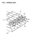
- this type of power source apparatus contains battery modules 71 housed in a case 70 .
- Battery modules 71 housed in the case 70 have output terminals 72 made up of bolts and nuts fixed at both ends.
- Output terminals 72 of the battery modules 71 are connected in series at bus-bars 73 .
- End-plates 74 containing the bus-bars 73 are provided at side regions of the case 70 .
- the end-plates 74 are formed of molded plastic with bus-bars inserted in the end-plates during molding for insulation.
- output terminals 72 of the battery modules 71 are connected to the bus-bars 73 by fastening battery module bolts 75 and nuts 76 to the end-plate 74 bus-bars 73 .
- a battery module made up of six of these rechargeable batteries connected in a straight line will have a maximum length error of ⁇ 1.8 mm. in this case, approximately 3 mm of length difference can develop between longest and shortest battery modules. Consequently, when battery modules of different lengths are disposed in adjacent, parallel positions and tightly connected with a bus-bar, considerable stress is exerted on long and short battery modules.
- a configuration which connects bus-bars to an end-plate while allowing some play, can absorb battery module length dimension error.
- this configuration has the drawback that the structure is complex and manufacturing cost is high. Further, if adjacent battery modules have different lengths, bus-bars cannot be connected without some force even when they are connected to end-plates with this configuration. This is because one bus-bar connected to battery modules with different lengths will have an inclined orientation connected to the output terminals.
- the power source apparatus shown in FIG. 1 has the drawback that the case itself has a complex structure. This is because of the requirement for end-plates formed by mold-insertion of the bus-bars. Since bus-bars cannot, be completely buried in the end-plates leaving bus-bar surfaces exposed, these regions must be further insulated by covering them with insulating plates. Further, since nuts and bolts are fixed to battery modules, the structure to attach output terminals to battery modules becomes complex. This is because nuts and bolts cannot be directly weld-attached to an end-plane of a battery in a battery module. It is necessary to first attach nuts and bolts to a metal plate by a method such as welding, then weld-attach the metal plate to a battery end-plane. This has the drawback that the structure is complex and assembly is time consuming.
- a power source apparatus with the structure shown in FIG. 1 has the drawback that replacement of a specific battery module, when that battery module has failed, is extremely difficult. This is because it is necessary to remove the end-plates 74 to replace a battery module. To remove an end-plate 74 , it is necessary to remove all nuts 76 and bolts 75 connected to battery modules 71 . Since several tens of battery modules are housed in a case, it is extremely troublesome to remove all nuts and bolts and remove the end-plates.
- the present invention was developed to correct these drawbacks. It is thus a primary object of the present invention to provide a power source apparatus with a simple structure allowing battery modules of different lengths to be joined without applying excessive force, allowing battery modules to be mounted in a case in a manner preventing their rotation without providing a special structure to prevent rotation, and also allowing extremely efficient and simple assembly and battery module replacement with a simple case structure.
- the power source apparatus of the present invention has a plurality of battery modules housed in a case, and these battery modules are connected by bus-bars.
- Battery modules are made up of a plurality of batteries connected in a straight line fashion. Battery modules have metal plate output terminals attached at both ends to battery end-planes in a manner projecting outward from the end-planes.
- the power source apparatus has a case which houses battery modules with adjacent battery module output terminals connected via metal plate bus-bars.
- the power source apparatus described above has the characteristic that battery modules of different lengths can be connected in a simple configuration without applying excessive force. This is because battery modules have metal plate output terminals attached at both ends perpendicular to, and projecting from battery end-planes, adjacent battery module output terminals are joined by metal plate bus-bars, and the assembly is housed in a case. In a power source apparatus of this configuration, output terminals attached to both ends of the battery modules face perpendicular to the axis of the battery module, not in the direction of the axis. For this reason even when battery modules of different lengths are disposed in a case in a parallel fashion and tightly connected via bus-bars, application of excessive force between battery modules can be reliably prevented while length differences are absorbed. Further, since the surface of metal plate output terminals projecting perpendicular from both ends of a battery module can support battery modules housed in the case, battery modules can be held in the case without rotation via a simple structure and without providing a special configuration to prevent battery module rotation.
- the power source apparatus described above does not require molded end-plates with inserted bus-bars as in prior art, it has the characteristic that the structure of the case itself is simple and manufacturing cost can be reduced. Still further, the power source apparatus described above has the characteristic that a specific battery module can be easily and extremely efficiently replaced when it falls. This is because only the section of the case housing the battery module for replacement needs to be disassembled, not all the nuts and bolts and end-plate as in the prior art.
- An output terminal preferably has a through-hole to accommodate a bus-bar attachment bolt.
- This through-hole can be a long narrow opening extending in the lengthwise direction of the battery module for the purpose of connecting to a bus-bar while absorbing battery module length variation.
- the case can be provided with insertion sections to hold bus-bars and output terminals.
- the case can hold bus-bars and output terminals in the insertion sections and retain battery modules in fixed positions.
- the case insertion sections can be provided with enough tolerance to absorb errors in battery module length.
- Nuts can be fixed to bus-bars. Bolts can be inserted through output terminal through-holes and screwed into nuts attached to the bus-bars to join output terminals and bus-bars in a more reliable fashion.
- FIG. 1 is an exploded perspective view of a prior art power source apparatus.
- FIG. 2 is a side view in cross-section of an embodiment of the power source apparatus of the present invention.
- FIG. 3 is a length-wise cross-section view of the power source apparatus shown in FIG. 2 .
- FIG. 4 is a plan view showing the power source apparatus shown in FIG. 2 with the upper case removed.
- FIG. 5 is a perspective view of a battery module.
- FIG. 6 is an enlarged cross-section view showing the structure joining batteries in the battery module shown in FIG. 5 .
- FIG. 7 is a plan view showing the battery connector of the battery module shown in FIG. 6 .
- FIG. 8 is a cross-section view taken along line A—A of the connector shown in FIG. 7 .
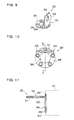
- FIG. 9 is a perspective view of an output terminal which connects to one end of a battery module.
- FIG. 10 is a plan view of the output terminal shown in FIG. 9 .
- FIG. 11 is a cross-section view taken along line A—A of the output terminal shown in FIG. 10 .
- FIG. 12 is a front view of an output terminal which connects to the other end of a battery module.
- FIG. 13 is a cross-section view taken along line A—A of the output terminal shown in FIG. 12 .
- FIG. 14 is a cross-section view taken along line B—B of the output terminal shown in FIG. 12 .
- FIG. 15 is a side view showing two battery modules joined together.
- FIG. 16 is an exploded perspective view of the power source apparatus shown in FIG. 4 .
- FIG. 17 is a perspective view of a bus-bar.
- the power source apparatus shown in FIGS. 2-4 has a plurality of battery modules 20 housed in a case 10 .
- Battery modules comprise a plurality of batteries 21 connected in a straight line, and adjacent battery modules 20 are connected in series via bus-bars 40 .
- the case 10 is made up of an upper case 11 and a lower case 12 .
- FIG. 2 shows a side cross-section view
- FIG. 3 shows a length-wise cross-section view
- FIG. 4 shows a plan view of the power source apparatus with the upper case 11 removed.
- the power source apparatus shown in these and other figures is primarily used in electric powered automobiles such as hybrid cars. However, the power source apparatus of the present invention can also be used for applications demanding high power output other than electric powered automobiles.
- battery modules shown in the figures have rechargeable batteries 21 , which are circular cylindrical batteries, connected in series in a straight line fashion. However, the battery modules may also use square or polygonal batteries.
- nickel hydrogen batteries Any batteries which can be charged, such as nickel hydrogen batteries, lithium ion rechargeable batteries, or nickel cadmium batteries can be used.
- nickel hydrogen batteries are suitable as rechargeable batteries for use in electric powered automobile battery arrays. This is because nickel hydrogen batteries have large output per unit volume and weight, and have excellent high current characteristics.
- a rechargeable battery 21 has an outer casing 25 with an opening hermetically sealed with a closing plate 23 .
- the outer casing 25 and closing plate 23 are formed from metal sheet.
- outer casing 25 is made by press-forming metal sheet into a cylindrical shape with a closed bottom.
- the closing plate 23 has a protruding electrode 22 welded at its center. Battery electrodes (not illustrated) are contained inside the outer casing 25 .
- the outer casing 25 is also filled with electrolyte solution.
- the closing plate 23 is hermetically attached at the opening of the outer casing 25 by crimping the edge of the opening.
- the closing plate 23 is hermetically attached via a gasket 19 sandwiched between the crimped outer casing 25 edge and the closing plate 23 .
- the gasket 19 is an insulating rubber-like flexible material which electrically insulates the closing plate 23 from the outer casing 25 as well as hermetically seals the gap between the closing plate 23 and the outer casing 25 .
- a crimp ring 24 is established around the perimeter of the closing plate 23 .
- the closing plate 23 forms the first electrode of this rechargeable battery 21
- the outer casing 25 forms the second electrode.
- the first electrode is the positive electrode and the second electrode is the negative electrode.
- a rechargeable battery can also have the first electrode as the negative electrode and the second electrode as the positive electrode.
- connectors 26 are disposed between rechargeable batteries 21 , and these connectors 26 connect rechargeable batteries 21 of a battery module 20 in series.
- the is closing plate 23 of one rechargeable battery 21 is joined to the outer casing 25 of another rechargeable battery 21 via a connector 26 .
- a connector 26 is press-formed from metal sheet, it is weld connected to opposing end-planes of adjacent rechargeable batteries 21 , and it electrically connects the rechargeable batteries 21 in series.
- FIGS. 7 and 8 show a connector 26 .
- FIG. 7 is a plan view of a connector 26 and FIG. 8 is a cross-section view.
- a connector of this type is formed from metal sheet in an annular shape, and is provided with a plurality of weld projections 27 which extend from both sides for welding to battery end-planes. Weld projections 27 extending from both sides of a connector 26 are welded to opposing battery end-planes to connect adjacent rechargeable batteries 21 in series.
- the connector 26 of the figures is provided with a center hole 28 , and a protruding electrode 22 is disposed in this center hole 28 .
- the connector 26 shown in FIGS. 7 and 8 has an outside diameter smaller than the inside diameter of the crimp ring 24 established on the battery end-plane. Since the closing plate 23 of the rechargeable battery 21 is the first electrode and the outer casing 25 is the second electrode, a short circuit will result if the connector 26 joined to the closing plate 23 touches the crimp ring 24 , which is part of the outer casing 25 .
- This connector 26 is provided with a gap between its outer edge and the crimp ring 24 to prevent short circuit caused by contact between the connector 26 and the crimp ring 24 . Since the connector 26 may contact the crimp ring 24 if it becomes misaligned, a retaining cap 26 holds the connector 26 in a fixed position.
- a plurality of weld projections 27 are established on a single circular arc of the connector 26 .
- Weld projections 27 project alternately from opposite sides of the connector 26 ; namely they project alternately upward and downward in FIG. 8 .
- Weld projections 27 projecting from opposite sides of a connector 26 are welded to opposing battery end-planes to connect those batteries.
- a battery module 20 has metal plate output terminals 30 attached at both ends perpendicular to, and projecting from the battery end-planes. Adjacent battery module 20 output terminals 30 are connected by metal plate bus-bars 40 .
- the bus-bars 40 connect battery modules 20 in series.
- the battery modules 20 are connected by bus-bars 40 and installed in the case 10 in that configuration.
- FIGS. 9-14 show output terminals 30 which connect to both ends of a battery module 20 .
- the output terminal 30 shown in FIGS. 9-11 has a different shape than the output terminal 30 shown in FIGS. 12-14.
- Output terminals 30 of different shapes are attached to battery module 20 positive and negative battery end-planes. Since different shaped output terminals 30 are attached to positive and negative ends of the battery modules 20 , they can be installed in the case 10 without mistaking their polarity.
- the output terminals 30 shown in the figures described above have attachment plates 35 for welding to battery end-planes.
- An attachment plate 35 is oriented perpendicular to the main part 31 of an output terminal 30 .
- the main part 31 of an output terminal 30 joins the output terminal 30 to a bus-bar 40 .
- An output terminal 30 with an attachment plate 35 can be securely weld-attached to the battery end-plane of a battery module 20 .
- an output terminal does not always have to be provided with an attachment plate. Namely, a planar output terminal cut to a specified shape from metal plate can also be fixed to the end-plane of a battery by welding a lateral edge.
- an output terminal 30 made up of an attachment plate 35 and a main part 31 has two metal pieces bent at right angles which are welded together to overlap and form a double layer at the main part 31 .
- the metal sheet of each metal piece is bent in a right angle to form the attachment plate 35 and main part 31 .
- the two metal pieces are shaped to form a circular attachment plate 35 by weld attaching the them together to form a double layer at the main part 31 .
- An output terminal 30 made by welding together two metal pieces bent at right angles at the boundary between the attachment plate 35 and the main part 31 , can be inexpensively manufactured in quantity. Further, compared to an output terminal made by forming an attachment plate and main part as metal plates and welding them together at the boundary, this bent metal piece structure has superior bending strength at the boundary between the attachment plate 35 and main part 31 .
- Output terminal 30 attachment plates 35 which attach to positive and negative ends of a battery module 20 have different shapes. As shown in the cross-section view of FIG. 11, the output terminal 30 of FIGS. 9-11 is weld-attached to the protruding electrode 22 end of a rechargeable battery 21 . This output terminal 30 attachment plate 35 is weld-attached to the battery closing plate 23 , which is the first electrode of the rechargeable battery 21 . If the attachment plate 35 connected to the battery closing plate 23 contacts the crimp ring 24 , which is part of the outer casing 25 , a short circuit will occur. Consequently, the outside diameter of the output terminal 30 attachment plate 35 is made smaller than the inside diameter of the rechargeable battery 21 crimp ring 24 .
- this attachment plate 35 has a center hole 36 to insert the protruding electrode 22 on the battery end-plane.
- This output terminal 30 is attached by inserting the battery protruding electrode 22 through the center hole 36 of the attachment plate 35 and welding the attachment plate 35 to the battery end-plane closing plate 23 .
- the output terminal 30 of FIGS. 12-14 is weld-attached to the planar electrode end of a rechargeable battery 21 .
- the outside diameter of this output terminal 30 attachment plate 35 is made slightly smaller than the outside diameter of the rechargeable battery 21 end-plane.
- This output terminal 30 is attached by welding the attachment plate 35 to the bottom of the rechargeable battery 21 outer casing 25 , which is the second electrode of the rechargeable battery 21 .
- An output terminal 30 is provided with a through-hole 32 in the main part 31 for insertion of a bolt 45 to join a bus-bar 40 .
- this through-hole 32 is a long narrow hole extending in the lengthwise direction of the battery module 20 , and the through-hole 32 allows bus-bar 40 connection while absorbing battery module 20 length variation.
- the output terminal 30 of FIG. 9 is provided with projections 33 on both side edges of the main part 31
- the output terminal 30 of FIG. 13 is provided with indentations 34 on both side edges of the main part 31 . Projections 33 and indentations 34 on the main part 31 fit into insertion sections 50 provided in the case 10 .
- output terminal 30 fixed to both ends of a battery module 20 have main parts 31 positioned to allow two battery modules 20 to be joined in a straight line.
- a plurality of battery modules 20 of this type can be joined in series in a straight line.
- the case 10 houses a plurality of battery modules 20 assembled in a parallel array in a single plane.
- the case 10 is made up of an upper case 11 and lower case 12 , and the upper and lower cases sandwich the battery modules 20 to retain them in fixed positions.
- the upper case 11 and the lower case 12 are securely joined in a detachable manner by fastening screws and nuts.
- the upper case 11 and lower case 12 shown in FIGS. 2 and 3 are provided with opposing inside surface battery grooves 13 to accept the battery sections of battery modules 20 .
- both side walls of the upper and lower cases are provided with insertion sections 50 to sandwich output terminals 30 and bus-bars 40 at both ends of the battery modules 20 .
- FIG. 16 is a detailed perspective view showing an insertion section 50 to provided in a lower case 12 side wall to accept output terminals 30 and a bus-bar 40 .
- the insertion section 50 is a cavity provided in the surface of a side wall, and the insertion section 50 of this and other figures is provided with a bus-bar insertion section 51 to hold a bus-bar 40 and an output terminal insertion section 52 to hold the main parts 31 of output terminals 30 .
- the output terminal insertion section 52 is provided above the bus-bar insertion section 51 .
- the bus-bar insertion section 51 inside surface is shaped equivalent to, or slightly larger than the outline of a bus-bar 40 to hold it in position without shifting, As shown in FIGS. 16 and 17, the bus-bar insertion section 51 is provided with a level change 53 in its bottom to fit the bus-bar 40 , which is bent to form a level change 42 along its length. As shown in FIG. 15, a level change 42 is provided along the bus-bar 40 to allow battery modules 20 to connect in a straight line without gaps between output terminals 30 . This is done by slightly offsetting positive and negative output terminals 30 from the battery module 20 center-line. Further, a bus-bar insertion section 51 is provided with cavities 54 in its bottom to accept nuts 41 fixed to the bottom surface of a bus-bar 40 .
- An output terminal insertion section 52 is configured to allow insertion of output terminals 30 of battery modules 20 which have error in their length.
- the inside shape of the output terminal insertion section 52 allows insertion of a pair of output terminals 30 joined to a bus-bar 40 , and the inside shape allows insertion of the main part 31 of the output terminal 30 attached to a battery module 20 of maximum length.
- the perimeter of the output terminal insertion section 52 is provided with positioning sections 55 to mate with projections 33 and indentations 34 provided on the main part 31 of positive and negative output terminals 30 .
- the positioning section 55 which mates with a main part 31 projection 33 has the form of a cavity
- the positioning section 55 which mates with a main part 31 indentation 34 has the form of a projection.
- These positioning sections 55 are configured with play in the lengthwise direction of the battery modules 20 , and they allow insertion of output terminals 30 of battery modules 20 with error in their length dimension. Further, an output terminal insertion section 52 is provided with a projection 56 between each pair of output terminals 30 . The projection 56 can retain the projection 33 provided on the main part 31 of an output terminal 30 .
- the inside surfaces of the battery grooves 13 provided in the upper case 11 and lower case 12 are made slightly larger than the outline of the battery sections of battery modules 20 . This is for the purpose of providing cooling gaps 14 to pass cooling air between the inside surfaces of the battery grooves 13 and battery module 20 surfaces. Further, ventilation holes 15 are opened through the bottoms of the battery grooves of the upper case 11 and lower case 12 . Cooling air vented into the case 10 from ventilation holes 15 is forced through the cooling gaps 14 . Air passing through the cooling gaps 14 flows over battery module 20 surfaces to cool the battery modules 20 .
- the bus-bars 40 have nuts 41 attached to their bottom surfaces. Output terminals 30 can be easily attached to this type of bus-bar 40 . As shown in FIG. 16, this is because bolts 45 can be screwed into output terminal 30 through-holes 32 for attachment.
- a power source apparatus as described above is assembled as follows.
- Output terminals 30 are weld-attached to both ends of the battery modules 20 . Different shaped output terminals 30 are attached to positive and negative ends of the battery modules 20 .
- Bus-bars 40 are inserted into the lower case 12 bus-bar insertion section 51 . Nuts 41 attached to bus-bar 40 bottom surfaces are inserted into bus-bar insertion section 51 cavities 54 . In this configuration, bus-bars 40 fit into fixed locations in the lower case 12 .
- Battery modules 20 are loaded into lower case 12 battery grooves 13 arranging them in a parallel fashion. At this point battery module 20 output terminals 30 rest on top of the bus-bars 40 .
- Bolts 45 are inserted into output terminal 30 through-holes 32 . These bolts 45 are screwed into nuts 41 fixed to the bottom sides of the bus-bars 40 joining output terminals 30 to bus-bars 40 . Battery modules 20 loaded into the lower case 12 have adjacent output terminals 30 joined by bus-bars 40 making a series connection.
Landscapes
- Chemical & Material Sciences (AREA)
- Chemical Kinetics & Catalysis (AREA)
- Electrochemistry (AREA)
- General Chemical & Material Sciences (AREA)
- Inorganic Chemistry (AREA)
- Connection Of Batteries Or Terminals (AREA)
- Battery Mounting, Suspending (AREA)
Applications Claiming Priority (2)
| Application Number | Priority Date | Filing Date | Title |
|---|---|---|---|
| JP24806/2002 | 2002-01-31 | ||
| JP2002024806A JP3671007B2 (ja) | 2002-01-31 | 2002-01-31 | 電源装置 |
Publications (2)
| Publication Number | Publication Date |
|---|---|
| US20030141842A1 US20030141842A1 (en) | 2003-07-31 |
| US6819081B2 true US6819081B2 (en) | 2004-11-16 |
Family
ID=19192289
Family Applications (1)
| Application Number | Title | Priority Date | Filing Date |
|---|---|---|---|
| US10/353,020 Expired - Fee Related US6819081B2 (en) | 2002-01-31 | 2003-01-29 | Power source apparatus |
Country Status (6)
| Country | Link |
|---|---|
| US (1) | US6819081B2 (ja) |
| EP (1) | EP1333511B1 (ja) |
| JP (1) | JP3671007B2 (ja) |
| KR (1) | KR100872954B1 (ja) |
| CN (1) | CN1271732C (ja) |
| DE (1) | DE60321067D1 (ja) |
Cited By (17)
| Publication number | Priority date | Publication date | Assignee | Title |
|---|---|---|---|---|
| US20050174092A1 (en) * | 2003-10-28 | 2005-08-11 | Johnson Controls Technology Company | Battery system |
| US20060076923A1 (en) * | 2004-08-13 | 2006-04-13 | Eaves Stephen S | Methods and systems for assembling batteries |
| WO2006112628A1 (en) * | 2005-04-19 | 2006-10-26 | Lg Chem, Ltd. | Terminal-connecting means |
| US20070178377A1 (en) * | 2006-02-02 | 2007-08-02 | Samsung Sdi Co., Ltd. | Cell barrier for secondary battery module and secondary battery module |
| US20080124618A1 (en) * | 2006-11-29 | 2008-05-29 | Yoshiro Shimoyama | Holder for battery modules |
| US20080220326A1 (en) * | 2007-03-08 | 2008-09-11 | Samsung Sdi Co., Ltd. | Battery module and method of manufacturing the same |
| WO2009023775A3 (en) * | 2007-08-14 | 2009-04-16 | Cobasys Llc | Battery module |
| US20110117792A1 (en) * | 2009-11-13 | 2011-05-19 | Sumitomo Wiring Systems, Ltd. | Terminal block and method of assembling it |
| US20110130049A1 (en) * | 2009-11-30 | 2011-06-02 | Sumitomo Wiring Systems, Ltd. | Busbar circuit structure and terminal block |
| US20110287298A1 (en) * | 2010-05-20 | 2011-11-24 | Shi-Dong Park | Battery pack |
| US8307967B2 (en) | 2007-07-04 | 2012-11-13 | Satyajit Patwardhan | Widely deployable charging system for vehicles |
| US20130071726A1 (en) * | 2011-09-16 | 2013-03-21 | Duk-Jung Kim | Rechargeable battery |
| US9605478B2 (en) | 2011-03-11 | 2017-03-28 | Lutron Electronics Co., Inc. | Motorized window treatment |
| US10494864B2 (en) | 2011-03-11 | 2019-12-03 | Lutron Technology Company Llc | Motorized window treatment |
| US10655386B2 (en) | 2011-03-11 | 2020-05-19 | Lutron Technology Company Llc | Motorized window treatment |
| US10707456B2 (en) | 2015-10-22 | 2020-07-07 | Lg Chem, Ltd. | Battery connecting unit and battery pack including the same |
| US11973237B2 (en) | 2020-02-25 | 2024-04-30 | Milwaukee Electric Tool Corporation | Battery pack |
Families Citing this family (37)
| Publication number | Priority date | Publication date | Assignee | Title |
|---|---|---|---|---|
| KR100556101B1 (ko) * | 2003-12-16 | 2006-03-03 | 주식회사 엘지화학 | 이차전지 모듈 |
| US7479346B1 (en) * | 2004-08-13 | 2009-01-20 | Quallion Llc | Battery pack |
| KR100876456B1 (ko) | 2004-12-24 | 2008-12-29 | 주식회사 엘지화학 | 분리형 커넥팅 부재 및 그것을 이용한 이차전지 모듈의제조방법 |
| MX2007011126A (es) * | 2005-03-16 | 2007-11-13 | Ford Global Tech Llc | Sistema de suministro de energia. |
| CN101395781B (zh) | 2005-03-16 | 2011-09-14 | 福特全球技术公司 | 电源温度传感器和系统 |
| US7604896B2 (en) * | 2005-03-16 | 2009-10-20 | Ford Global Technologies, Llc | High voltage battery assembly for a motor vehicle |
| KR100857019B1 (ko) * | 2005-04-19 | 2008-09-05 | 주식회사 엘지화학 | 기계적 및 전기적 커넥팅 부재 |
| KR100846556B1 (ko) | 2006-11-22 | 2008-07-15 | 엘지전자 주식회사 | 전자 제품의 전지지지장치 |
| CN102361066B (zh) | 2007-01-12 | 2014-09-10 | 丰田自动车株式会社 | 电极 |
| KR100924724B1 (ko) * | 2007-09-14 | 2009-11-04 | 에너지 컨트롤 리미티드 | 독립 분리형 전력 전지 조립체 |
| KR101103755B1 (ko) * | 2008-09-03 | 2012-01-06 | 에스케이이노베이션 주식회사 | 버스 바 구비 리튬 2차 전지 단위 셋 및 버스 바 구비 리튬2차 전지 셋 |
| CN101399363B (zh) * | 2008-10-21 | 2012-04-18 | 微宏动力系统(湖州)有限公司 | 电池组 |
| US20100181962A1 (en) * | 2009-01-21 | 2010-07-22 | Chen Shih Chung | Nondirectional Radio Frequency Rechargeable Dry Cell |
| WO2010141854A1 (en) * | 2009-06-05 | 2010-12-09 | K2 Energy Solutions, Inc. | Lithium ion battery pack having passive cooling |
| EP2441103B2 (de) * | 2009-06-08 | 2018-09-12 | Auto-Kabel Management GmbH | Batteriezellenverbinder |
| KR101106544B1 (ko) * | 2009-06-17 | 2012-01-20 | 강정욱 | 기구물체결방식의 유닛팩 조합형 셀 카트리지 |
| KR101199179B1 (ko) | 2010-06-09 | 2012-11-07 | 삼성에스디아이 주식회사 | 전지스택의 전원단 연결구조 |
| JP2012054138A (ja) * | 2010-09-02 | 2012-03-15 | Makita Corp | 工具用バッテリ |
| US8790823B2 (en) | 2011-02-08 | 2014-07-29 | Samsung Sdi Co., Ltd. | Battery unit and battery pack having less resistance and improved contacts |
| JP5592341B2 (ja) * | 2011-12-09 | 2014-09-17 | 本田技研工業株式会社 | バッテリモジュールユニット |
| US20150104676A1 (en) * | 2012-06-11 | 2015-04-16 | Sanyo Electric Co., Ltd. | Battery for automotive electrical system |
| JP6086315B2 (ja) * | 2013-03-19 | 2017-03-01 | 株式会社Gsユアサ | 蓄電装置 |
| CN103258982B (zh) * | 2013-05-16 | 2015-10-28 | 江苏新日电动车股份有限公司 | 一种用于电器动力系统的电池盒 |
| US9166425B1 (en) * | 2013-07-03 | 2015-10-20 | Billy White | Battery charging storage device |
| KR102073193B1 (ko) * | 2013-09-23 | 2020-02-04 | 삼성에스디아이 주식회사 | 배터리 팩 |
| KR102211369B1 (ko) | 2014-03-19 | 2021-02-03 | 삼성에스디아이 주식회사 | 배터리 모듈 |
| US9437860B2 (en) * | 2014-11-20 | 2016-09-06 | Ford Global Technologies, Llc | Traction battery assembly having snap-in bus bar module |
| KR101970250B1 (ko) * | 2017-07-03 | 2019-04-18 | 엘지전자 주식회사 | 배터리 셀이 분리 가능하게 결합되는 배터리 모듈 |
| CA3070879C (en) | 2017-08-30 | 2023-04-04 | The Noco Company | Portable rechargeable battery jump starting device |
| JP7224341B2 (ja) * | 2017-08-30 | 2023-02-17 | ザ・ノコ・カンパニー | 充電式バッテリジャンプスタート装置及び充電式バッテリアセンブリ |
| CA3072566C (en) | 2017-08-30 | 2023-04-04 | The Noco Company | A rechargeable jump starting device having a highly electrically conductive cable connecting device |
| WO2019060135A1 (en) | 2017-09-22 | 2019-03-28 | The Noco Company | RECHARGEABLE BATTERY BACKUP DEVICE HAVING CONTROLLER SWITCHING BACKLIGHT SYSTEM |
| GB2607260A (en) * | 2017-09-22 | 2022-11-30 | Noco Co | Rechareable battery jump starting device and battery frame |
| KR102387356B1 (ko) * | 2019-02-21 | 2022-04-14 | 주식회사 엘지에너지솔루션 | 유동 너트를 구비한 단자 연결구조를 갖는 전지 모듈과 이를 포함한 전지 팩 |
| DE102021201288A1 (de) | 2021-02-11 | 2022-08-11 | Volkswagen Aktiengesellschaft | Batteriesystem, Modul-Verbinder und Verfahren zum Austausch eines defekten Zellmoduls aus einem Batteriesystem |
| CN115843398B (zh) * | 2021-07-21 | 2023-12-15 | 宁德时代新能源科技股份有限公司 | 电池、用电设备、制备电池的方法和设备 |
| JPWO2025013567A1 (ja) * | 2023-07-13 | 2025-01-16 |
Citations (7)
| Publication number | Priority date | Publication date | Assignee | Title |
|---|---|---|---|---|
| US4322597A (en) * | 1980-06-30 | 1982-03-30 | General Electric Company | Method and apparatus for interconnecting electrochemical cells for a battery |
| EP0892450A2 (en) | 1997-03-24 | 1999-01-20 | Matsushita Electric Industrial Co., Ltd. | Battery power source unit |
| US6152776A (en) | 1997-10-13 | 2000-11-28 | Yazaki Corporation | Connecting plate for a battery holder |
| US6287150B1 (en) | 1999-02-19 | 2001-09-11 | Sanyo Electric Co., Ltd. | Power source |
| US6340877B1 (en) * | 1999-12-28 | 2002-01-22 | Honda Giken Kogyo Kabushiki Kaisha | Rechargeable cell support device with insulating rings |
| US6465123B1 (en) * | 1999-07-01 | 2002-10-15 | Daimlerchrysler Ag | Battery container and motor vehicle |
| US6541154B2 (en) * | 2000-03-15 | 2003-04-01 | Nissan Motor Co., Ltd. | Multi-cell structure battery for electric motor powered vehicle |
Family Cites Families (3)
| Publication number | Priority date | Publication date | Assignee | Title |
|---|---|---|---|---|
| JPH09190811A (ja) * | 1996-01-09 | 1997-07-22 | Furukawa Battery Co Ltd:The | 蓄電池の極柱端子間接続器具 |
| JP3777748B2 (ja) * | 1997-09-30 | 2006-05-24 | 株式会社ジーエス・ユアサコーポレーション | 組電池 |
| JP2000323109A (ja) * | 1999-05-12 | 2000-11-24 | Toyota Central Res & Dev Lab Inc | 電池モジュール |
-
2002
- 2002-01-31 JP JP2002024806A patent/JP3671007B2/ja not_active Expired - Fee Related
-
2003
- 2003-01-16 CN CNB031015239A patent/CN1271732C/zh not_active Expired - Fee Related
- 2003-01-28 EP EP03001792A patent/EP1333511B1/en not_active Expired - Lifetime
- 2003-01-28 DE DE60321067T patent/DE60321067D1/de not_active Expired - Lifetime
- 2003-01-29 US US10/353,020 patent/US6819081B2/en not_active Expired - Fee Related
- 2003-01-30 KR KR1020030006053A patent/KR100872954B1/ko not_active Expired - Fee Related
Patent Citations (8)
| Publication number | Priority date | Publication date | Assignee | Title |
|---|---|---|---|---|
| US4322597A (en) * | 1980-06-30 | 1982-03-30 | General Electric Company | Method and apparatus for interconnecting electrochemical cells for a battery |
| EP0892450A2 (en) | 1997-03-24 | 1999-01-20 | Matsushita Electric Industrial Co., Ltd. | Battery power source unit |
| EP1030389A2 (en) | 1997-03-24 | 2000-08-23 | Matsushita Electric Industrial Co., Ltd. | Battery power source unit |
| US6152776A (en) | 1997-10-13 | 2000-11-28 | Yazaki Corporation | Connecting plate for a battery holder |
| US6287150B1 (en) | 1999-02-19 | 2001-09-11 | Sanyo Electric Co., Ltd. | Power source |
| US6465123B1 (en) * | 1999-07-01 | 2002-10-15 | Daimlerchrysler Ag | Battery container and motor vehicle |
| US6340877B1 (en) * | 1999-12-28 | 2002-01-22 | Honda Giken Kogyo Kabushiki Kaisha | Rechargeable cell support device with insulating rings |
| US6541154B2 (en) * | 2000-03-15 | 2003-04-01 | Nissan Motor Co., Ltd. | Multi-cell structure battery for electric motor powered vehicle |
Cited By (28)
| Publication number | Priority date | Publication date | Assignee | Title |
|---|---|---|---|---|
| US8632898B2 (en) | 2003-10-28 | 2014-01-21 | Johnson Controls Technology Company | Battery system including batteries that have a plurality of positive terminals and a plurality of negative terminals |
| US20050174092A1 (en) * | 2003-10-28 | 2005-08-11 | Johnson Controls Technology Company | Battery system |
| US20060076923A1 (en) * | 2004-08-13 | 2006-04-13 | Eaves Stephen S | Methods and systems for assembling batteries |
| US7304453B2 (en) * | 2004-08-13 | 2007-12-04 | Modular Energy Devices, Inc. | Methods and systems for assembling batteries |
| WO2006112628A1 (en) * | 2005-04-19 | 2006-10-26 | Lg Chem, Ltd. | Terminal-connecting means |
| US9123956B2 (en) * | 2006-02-02 | 2015-09-01 | Samsung Sdi Co., Ltd. | Cell barrier for secondary battery module and secondary battery module |
| US20070178377A1 (en) * | 2006-02-02 | 2007-08-02 | Samsung Sdi Co., Ltd. | Cell barrier for secondary battery module and secondary battery module |
| US20080124618A1 (en) * | 2006-11-29 | 2008-05-29 | Yoshiro Shimoyama | Holder for battery modules |
| US20080220326A1 (en) * | 2007-03-08 | 2008-09-11 | Samsung Sdi Co., Ltd. | Battery module and method of manufacturing the same |
| US8481193B2 (en) * | 2007-03-08 | 2013-07-09 | Samsung Sdi Co., Ltd. | Battery module and method of manufacturing the same |
| US8307967B2 (en) | 2007-07-04 | 2012-11-13 | Satyajit Patwardhan | Widely deployable charging system for vehicles |
| WO2009023775A3 (en) * | 2007-08-14 | 2009-04-16 | Cobasys Llc | Battery module |
| US8142234B2 (en) | 2009-11-13 | 2012-03-27 | Sumitomo Wiring Systems, Ltd. | Terminal block and method of assembling it |
| US20110117792A1 (en) * | 2009-11-13 | 2011-05-19 | Sumitomo Wiring Systems, Ltd. | Terminal block and method of assembling it |
| US8337257B2 (en) * | 2009-11-30 | 2012-12-25 | Sumitomo Wiring Systems, Ltd. | Busbar circuit structure and terminal block |
| US20110130049A1 (en) * | 2009-11-30 | 2011-06-02 | Sumitomo Wiring Systems, Ltd. | Busbar circuit structure and terminal block |
| US20110287298A1 (en) * | 2010-05-20 | 2011-11-24 | Shi-Dong Park | Battery pack |
| US8603663B2 (en) * | 2010-05-20 | 2013-12-10 | Samsung Sdi Co., Ltd. | Battery pack |
| US10494864B2 (en) | 2011-03-11 | 2019-12-03 | Lutron Technology Company Llc | Motorized window treatment |
| US9605478B2 (en) | 2011-03-11 | 2017-03-28 | Lutron Electronics Co., Inc. | Motorized window treatment |
| US10655386B2 (en) | 2011-03-11 | 2020-05-19 | Lutron Technology Company Llc | Motorized window treatment |
| US11280131B2 (en) | 2011-03-11 | 2022-03-22 | Lutron Technology Company Llc | Motorized window treatment |
| US11480012B2 (en) | 2011-03-11 | 2022-10-25 | Lutron Technology Company Llc | Motorized window treatment |
| US12044069B2 (en) | 2011-03-11 | 2024-07-23 | Lutron Technology Company Llc | Motorized window treatment |
| US9153801B2 (en) * | 2011-09-16 | 2015-10-06 | Samsung Sdi Co., Ltd. | Rechargeable battery having a plate terminal and a bolt terminal |
| US20130071726A1 (en) * | 2011-09-16 | 2013-03-21 | Duk-Jung Kim | Rechargeable battery |
| US10707456B2 (en) | 2015-10-22 | 2020-07-07 | Lg Chem, Ltd. | Battery connecting unit and battery pack including the same |
| US11973237B2 (en) | 2020-02-25 | 2024-04-30 | Milwaukee Electric Tool Corporation | Battery pack |
Also Published As
| Publication number | Publication date |
|---|---|
| CN1435902A (zh) | 2003-08-13 |
| US20030141842A1 (en) | 2003-07-31 |
| KR100872954B1 (ko) | 2008-12-08 |
| CN1271732C (zh) | 2006-08-23 |
| JP2003229106A (ja) | 2003-08-15 |
| EP1333511B1 (en) | 2008-05-21 |
| EP1333511A2 (en) | 2003-08-06 |
| JP3671007B2 (ja) | 2005-07-13 |
| DE60321067D1 (de) | 2008-07-03 |
| EP1333511A3 (en) | 2004-03-10 |
| KR20030066382A (ko) | 2003-08-09 |
Similar Documents
| Publication | Publication Date | Title |
|---|---|---|
| US6819081B2 (en) | Power source apparatus | |
| US7160643B2 (en) | Battery pack | |
| KR101249110B1 (ko) | 전지 간 접속구조 | |
| JP5127864B2 (ja) | 電池モジュールの製造方法 | |
| US8658306B2 (en) | Electrode terminal connecting member for battery module | |
| US20110064993A1 (en) | Battery array with reliable low-resistance connections | |
| KR101326182B1 (ko) | 외장부재와 카트리지를 포함하는 단위모듈에 기반한 전지모듈 | |
| WO2006126447A1 (ja) | 電池モジュールおよびその製造方法 | |
| KR20140060633A (ko) | 버스 바 어셈블리를 포함하는 전지모듈 및 이를 포함하는 전지팩 | |
| KR20070043501A (ko) | 신규한 구조의 전기 접속용 버스 바 및 그것을 포함하고있는 전지모듈 | |
| KR100943833B1 (ko) | 중대형 전지팩용 카트리지 | |
| JP4275670B2 (ja) | リチウム二次電池モジュール | |
| KR20180080811A (ko) | 직렬 연결 구조를 갖는 배터리 팩 및 이의 조립 방법 | |
| CN217214989U (zh) | 电池 | |
| JP2005353547A (ja) | 電源装置 | |
| KR20120074426A (ko) | 신규한 구조의 단위모듈 및 이를 포함하는 전지모듈 | |
| US20030072997A1 (en) | Apparatus and method for connecting cells of a battery | |
| KR100590107B1 (ko) | 이차 전지 | |
| KR101859684B1 (ko) | 버스 바 어셈블리를 포함하는 전지모듈 및 이를 포함하는 전지팩 | |
| JP3920651B2 (ja) | 組電池 | |
| CN223401835U (zh) | 电池单元、电池包和车辆 | |
| US20250079659A1 (en) | Cap plate assembly, method of manufacturing cap plate assembly, and battery cell including the same | |
| KR100599806B1 (ko) | 이차 전지 모듈 | |
| TW202433793A (zh) | 電源裝置及電源裝置的製造方法 | |
| KR20230120756A (ko) | 분리형 카트리지를 이용한 배터리 팩 |
Legal Events
| Date | Code | Title | Description |
|---|---|---|---|
| AS | Assignment |
Owner name: SANYO ELECTRIC CO., LTD., JAPAN Free format text: ASSIGNMENT OF ASSIGNORS INTEREST;ASSIGNORS:IZAWA, RYOSAKU;KUNIMOTO, KIYOSHI;REEL/FRAME:013725/0506 Effective date: 20030117 |
|
| FEPP | Fee payment procedure |
Free format text: PAYOR NUMBER ASSIGNED (ORIGINAL EVENT CODE: ASPN); ENTITY STATUS OF PATENT OWNER: LARGE ENTITY |
|
| FPAY | Fee payment |
Year of fee payment: 4 |
|
| FPAY | Fee payment |
Year of fee payment: 8 |
|
| REMI | Maintenance fee reminder mailed | ||
| LAPS | Lapse for failure to pay maintenance fees | ||
| STCH | Information on status: patent discontinuation |
Free format text: PATENT EXPIRED DUE TO NONPAYMENT OF MAINTENANCE FEES UNDER 37 CFR 1.362 |
|
| STCH | Information on status: patent discontinuation |
Free format text: PATENT EXPIRED DUE TO NONPAYMENT OF MAINTENANCE FEES UNDER 37 CFR 1.362 |
|
| FP | Lapsed due to failure to pay maintenance fee |
Effective date: 20161116 |