US6752066B2 - Device for controlling the oscillation of the arm of a handling equipment of the swingable lever type - Google Patents
Device for controlling the oscillation of the arm of a handling equipment of the swingable lever type Download PDFInfo
- Publication number
- US6752066B2 US6752066B2 US10/252,550 US25255002A US6752066B2 US 6752066 B2 US6752066 B2 US 6752066B2 US 25255002 A US25255002 A US 25255002A US 6752066 B2 US6752066 B2 US 6752066B2
- Authority
- US
- United States
- Prior art keywords
- screw member
- chamber
- cylinder
- head portion
- piston
- Prior art date
- Legal status (The legal status is an assumption and is not a legal conclusion. Google has not performed a legal analysis and makes no representation as to the accuracy of the status listed.)
- Expired - Fee Related, expires
Links
Images


Classifications
-
- F—MECHANICAL ENGINEERING; LIGHTING; HEATING; WEAPONS; BLASTING
- F15—FLUID-PRESSURE ACTUATORS; HYDRAULICS OR PNEUMATICS IN GENERAL
- F15B—SYSTEMS ACTING BY MEANS OF FLUIDS IN GENERAL; FLUID-PRESSURE ACTUATORS, e.g. SERVOMOTORS; DETAILS OF FLUID-PRESSURE SYSTEMS, NOT OTHERWISE PROVIDED FOR
- F15B15/00—Fluid-actuated devices for displacing a member from one position to another; Gearing associated therewith
- F15B15/20—Other details, e.g. assembly with regulating devices
- F15B15/26—Locking mechanisms
- F15B15/262—Locking mechanisms using friction, e.g. brake pads
- F15B15/264—Screw mechanisms attached to the piston
-
- B—PERFORMING OPERATIONS; TRANSPORTING
- B25—HAND TOOLS; PORTABLE POWER-DRIVEN TOOLS; MANIPULATORS
- B25B—TOOLS OR BENCH DEVICES NOT OTHERWISE PROVIDED FOR, FOR FASTENING, CONNECTING, DISENGAGING OR HOLDING
- B25B5/00—Clamps
- B25B5/06—Arrangements for positively actuating jaws
- B25B5/12—Arrangements for positively actuating jaws using toggle links
- B25B5/122—Arrangements for positively actuating jaws using toggle links with fluid drive
-
- B—PERFORMING OPERATIONS; TRANSPORTING
- B25—HAND TOOLS; PORTABLE POWER-DRIVEN TOOLS; MANIPULATORS
- B25B—TOOLS OR BENCH DEVICES NOT OTHERWISE PROVIDED FOR, FOR FASTENING, CONNECTING, DISENGAGING OR HOLDING
- B25B5/00—Clamps
- B25B5/16—Details, e.g. jaws, jaw attachments
Definitions
- the present invention refers in general to handling equipments of the so-called swingable lever type.
- the invention relates to a device for controlling the oscillation of the arm of such an equipment comprising a driving double acting cylinder having a chamber in which a main piston is sealingly mounted, which is slidable as a result of the selective delivery of fluid under pressure at opposite zones of the chamber of the cylinder, the main piston being connected to a rod having a driving end which projects from the cylinder and is connected to said arm by a toggle joint.
- anomalous conditions can take place during delivery of fluid under pressure to the chamber of the cylinder, which may involve risks for the integrity of the equipments themselves and for the apparatuses which are associated to them, or for possible operators which may be close to such equipments.
- a first anomalous condition can take place in the case in which, for example after a maintenance operation carried out on the equipment, the feeding and the exhaust lines of the fluid under pressure are not correctly connected to the opposite ends of the cylinder, in particular if an end of the cylinder is connected to the feeding of the fluid under pressure while the other end freely communicates with the outside environment.
- the fluid under pressure is only fed to one of the cylinder ends, the piston is moved violently against the cylinder end in communication with the outside environment, causing the arm of the equipment to fall down suddenly to an end-of-travel position.
- brake devices for controlling the motion of the piston rod which operate on the basis of the principle to apply a friction force against the outside surface of the rod in the case of a pressure drop.
- brake devices may be used which include planes inclined with respect to the cylinder axis, to which rollers or balls are associated which are intended to interfere with the peripheral surface of the rod when a pressure drop below a predetermined threshold occurs.
- Other braking devices employ a laminar element having a through circular hole in which the rod is inserted, whose diameter is little greater than that of the rod.
- the sheet element in the operation with the fluid fed under normal pressure, the sheet element is perpendicular to the axis of the rod, whereby the rod can slide axially through it.
- the sheet element In the case of pressure drop, the sheet element is placed in a configuration inclined with respect to the rod axis, in order to cause interference between the edges of its through hole and the radial surface of the rod, which causes the axial locking of the latter.
- the devices mentioned above for controlling the movement of the rod, and therefore the oscillation of the arm may turn out to be not very practical or not very reliable in use.
- their operation can be affected by the dimensions of the mechanical members involved in the operation, so that the wear of one of the members of the device can jeopardize its good operation, such as the presence of foreign bodies, also if they are very small, in the fluid fed to the cylinder.
- the main object of the present invention is therefore to provide a handling equipment of the swingable lever type, whose structure is fitted with a device for controlling the oscillation of the arm, said device being able to prevent that malfunctions may take place as a consequence of the anomalous conditions of feeding mentioned above.
- the device comprises:
- a screw member comprising a threaded shank so arranged as to engage the nut screw of the rod, and a head portion opposite to the rod and mounted rotatably but not axially slidable with respect to the cylinder, and
- control means for controlling the rotating movement of the screw member, which are associated to the head portion of the screw member and are adapted to perform a braking action of its rotation when an anomalous condition occurs in the feeding of the fluid under pressure to the cylinder chamber.
- FIG. 1 is an elevational side view of a first embodiment of a swingable lever handling equipment provided with a control device according to the invention
- FIG. 2 is a view similar to that of FIG. 1, in cross-section,
- FIG. 3 is an enlarged view of a detail indicated by the arrow III in FIG. 2,
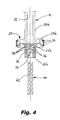
- FIG. 4 is a partial, enlarged and exploded view of a detail indicated by the arrow IV in FIG. 3,
- FIG. 5 is a schematic, partial front elevational view of an element of FIG. 3, taken along its line V—V,
- FIG. 6 is a schematic view of a portion of the element shown in FIG. 5, from the arrow VI,
- FIG. 7 is a side elevational view similar to FIG. 3, showing another embodiment of a swingable lever handling equipment provided with a control device according to the invention
- FIG. 8 is an elevational view sectioned along the line VIII—VIII of FIG. 7, which also shows an interception valve device associated to the control device,
- FIG. 9 is a view of a detail indicated by the arrow IX in FIG. 8, in a working condition different from that illustrated in FIG. 8, and
- FIGS. 10 and 11 are views showing a modification of the interception valve device associated to the control device, in two operating conditions respectively corresponding to those shown in FIGS. 8 and 9 .
- 1 indicates as a whole a handling equipment of the swingable lever type, which is operated by means of fluid under pressure, typically air.
- the equipment 1 comprises a body 3 to which a double acting fluid cylinder 5 is associated for driving a fork lever arm 7 by means of a toggle joint unit 9 .
- the joint 9 comprises, in a manner known per se, a link member 11 an end of which rotatably engages a pin 13 of a crank 15 , while the opposite end rotatably engages a hinge 12 associated to a driving end 10 a of a rod 10 .
- the crank 15 also comprises a pair of coaxial pins 17 spaced from the crank pin 13 , projecting outside the body 3 .
- Branches 20 of the arm 7 are connected to the pins 17 by keying devices 19 which are known per se.
- An attachment plate 20 a having holes and/or openings in order to allow connection of apparatuses (not shown in the figures) to be moved by the equipment 1 , is also fixed to the branches 20 .
- Each branch 20 of the arm 7 has a pair of protruding portions 7 a and 7 b on each of which a respective abutment surface 8 a , 8 b is formed.
- Such surfaces are intended to abut against a pair of projections 6 extending sideways with respect to the body 3 , or to reach a position close to them, when one of the end oscillation positions of the arm 7 is attained.
- the surfaces 8 a and 8 b are angularly spaced from each other of 90°, in such a way that the arm 7 can be mounted according to two configurations angled of 90° to each other, in order that the equipment 1 can be easily adapted to any possible use requirement.
- One of the two possible mounting conditions of the arm 7 is shown in FIG.
- a main piston 23 which is connected to the rod 10 , is slidably and sealingly mounted by annular seals 24 , inside a chamber 25 defined by the body of the cylinder 5 .
- the piston 23 is conveniently formed by two parts 23 a and 23 b connected to each other, for example by screw or other connecting members known per se, one of the two parts being formed integrally with the rod 10 .
- Each of the parts 23 a , 23 b has a sleeve portion 26 a , 26 b having a diameter slightly larger than that of the rod 10 .
- the chamber 25 is axially defined by a pair of heads 27 a and 27 b , respectively arranged at its end adjacent to the body 3 and at the opposite end. Respective feeding and exhaust lines 28 a , 28 b and 29 a , 29 b for the fluid under pressure are formed in the heads 27 a and 27 b .
- the lines 28 a and 28 b or 29 a and 29 b are selectively connected, by a switching device of a type known per se, with a source of fluid under pressure, in order to produce alternatively over-pressure conditions on one of the faces of the piston 23 , so as to cause the reciprocating motion of the piston 23 inside the chamber 25 between the heads 27 a and 27 b .
- Each of the lines 28 a , 28 b has preferably a pair of branch lines one of which ends in the chamber 25 facing a respective face of piston 23 , the other one ending into a seat 30 a , 30 b for receiving a respective sleeve portion 26 a , 26 b of the piston 23 when the piston is in an end-of-stroke position.
- An axial cavity 32 is formed inside the rod 10 and passes through the parts 23 a , 23 b of the piston 23 and through their sleeve portions 26 a , 26 b .
- a nut screw 34 is formed in the cavity 32 for the purposes that will be explained in the following.
- the nut screw 34 is preferably made by forming a plurality of axial grooves 36 with a semicircular bottom in the part 23 b of the piston, for example four, and by placing in each of them an array of balls 38 , for example three balls in each groove 36 .
- a screw member 40 is associated to the head 27 b in order to pass through it, at the opposite side of the body 3 with respect to the cylinder 5 .
- the screw member 40 has a threaded shank 42 which is coaxial with the cavity 32 so that its thread engages the nut screw 34 .
- the grooves 36 of the nut screw 34 are axially open at the surface of separation between the part 23 b and the part 23 a , so as to allow to introduce the balls 38 in the grooves 36 while the shank 42 is inserted in the cavity 32 of the part 23 b.
- the thread of the shank 42 is preferably a multi-start screw thread, for example a four-start thread, each start of which has a pitch which is large with respect to the diameter of the shank 42 so that the shank 42 can easily rotate about its own axis as a result of the reciprocating motion of the piston 23 , as a consequence of the engagement of the balls 38 in its thread.
- the screw member 40 has a head portion 44 extending in a service chamber 50 of a casing 46 fixed to the head 27 b .
- the service chamber 50 is connected with the source of fluid under pressure which selectively feed the feeding lines 28 a , 29 a or 28 b , 29 b through an opening 52 formed in the casing 46 , upstream the aforesaid switching device, in such a manner that fluid under pressure is admitted in the chamber 50 when the fluid is fed to one of the feeding lines.
- the head portion 44 is mounted in the chamber 50 in order to be rotatable and not axially slidable with respect to the casing 46 and to the cylinder 5 , by means of rolling bearings.
- an auxiliary floating piston 48 In the chamber 50 , at its side opposite to the head 27 b with respect to the head portion 44 , an auxiliary floating piston 48 , usually cup-shaped, is axially slidable and sealingly mounted so as not to rotate with respect to the casing 46 , the auxiliary floating piston 48 being urged towards the head portion 44 by elastic biasing means.
- These elastic means can conveniently be constituted by a gas spring 56 , preferably of the nitrogen type, having a push rod 58 resting on a surface of the piston 48 opposite to the head portion 44 .
- the facing surfaces of the head portion 44 and of the piston 48 are provided with corresponding mutually engaging formations, each of which is preferably formed by a crown gear 54 with radial front teeth 55 having a triangular shape, for example with their sides inclined of 60°, the toothings of the head portion 44 and of the piston 48 being equal to each other.
- the fluid under pressure coming from the source is selectively fed to the feeding lines 28 a , 29 a and 28 b , 29 b so as to cause the reciprocating motion of the piston 23 within the chamber 25 .
- the rod 10 controls the oscillation of the lever arm 7 and therefore of the apparatuses fixed to its attachment plate 20 a.
- the same source of the fluid under pressure is connected with the opening 52 of the casing 46 , upstream the switching device allowing to feed selectively the feeding lines, in such a way that in the same manner fluid under pressure is admitted inside the chamber 50 .
- the normal pressure of the fluid admitted in the chamber 50 is sufficient to oppose the elastic biasing action exerted by the elastic means 56 on the auxiliary piston 48 , in order to hold the piston 48 spaced from the head portion 44 of the screw member 40 , for example at a distance of a few millimeters.
- the screw member 40 freely rotates about the axis of the rod 10 within the cavity 32 as a result of the motion of the piston 23 .
- the control device of the present embodiment allows to lock in an extremely quick and effective manner the motion of the arm 7 in the case of lack or sudden drop of the pressure in the chamber 50 for any mounting position of the equipment 1 . It is moreover able to stop the movement of rod 10 in both its movement directions.
- decelerating units of a type known per se are conveniently used.
- Such decelerating units usually of the oil transfer type, are associated to the arm 7 at its abutment surfaces 8 a or 8 b depending on which one of these surfaces is intended to be arranged in abutment or close to a respective side projection 6 , namely on the basis of the selected angular mounting of the arm 7 with respect to the pins 17 .
- Each decelerating unit has a slidable stem 14 (FIG. 1) intended to abut on a respective side projection 6 , in order to dampen the impact of the branches 20 against the projections 6 , so as to slow down the arm 7 at its end-of-travel.
- FIGS. 7 to 9 in which the same reference numerals have been used for indicating elements equal or similar to those of the previous embodiment, the general structure of the cylinder 5 as well as of its piston 23 and the screw member 40 , is the same of the previous embodiment.
- the head portion of the screw member in this case indicated by the reference numeral 44 ′, is different from that of the previous embodiment in that it has an axial dead hole 60 opening towards the chamber 50 , in which an internal thread 62 is formed, for example with three start screw threads.
- the thread 62 is engaged by a corresponding external thread 64 formed at the end of a stem 66 axially extending from an auxiliary piston 48 ′ sealingly mounted in the chamber 50 , from its side facing the head portion 44 ′.
- the piston 48 ′ can slide axially in the chamber 50 but it cannot rotate with respect to the casing 46 .
- means for locking the rotation of piston 48 ′ are associated to the portion of the piston 48 ′ opposite to the stem 66 and to the bottom of the casing 46 , the locking means being for example constituted by a pair of axial pins 68 which are slidably mounted in holes made in the bottom of the casing 46 and which are fixed to the piston 48 ′, these pins being parallel and spaced with respect to the axis of the screw member 40 .
- a pair of transfer lines 70 , 72 respectively arranged in proximity of the head 27 b and in proximity of the bottom of the casing 46 , open in the chamber 50 and are connected to each other by a line 74 formed in the wall of the casing 46 .
- a viscous fluid, typically oil, is admitted in the chamber 50 , and is transferred through the lines 70 , 72 and 74 from one side to the other of the piston 48 ′ as a result of its movement inside the chamber 50 .
- a screw 75 with a conical end is preferably associated to the line 72 .
- the head of the screw 75 faces the outside of the casing 46 so that it can be driven by a driving tool such as a screwdriver in order to allow that the section of passage of the viscous fluid through the line 72 be modified for regulating the flow rate of such a fluid.
- the member 40 rotates as a result of the motion of the piston 23 in the chamber 25 of the cylinder 5 .
- the rotation of its head portion 44 ′ causes the axial motion of the auxiliary piston 48 ′, through the threads 62 and 64 , as a function of the movement of the main piston 23 , through a reduction ratio correlated to the pitch of the thread of the shank 42 and to the pitch of the threads 62 and 64 .
- the axial motion of the piston 48 ′ in the chamber 50 causes the movement of the viscous fluid through the lines 70 , 72 and 74 , causing a damping of the speed of movement of the auxiliary piston 48 ′, and therefore of the main piston 23 , which is a function of the flow rate of the fluid through the line 72 .
- a valve device adapted to intercept the flow of the viscous fluid crossing the lines 70 , 72 and 74 can be associated to the casing 46 when this anomalous operation condition occurs.
- a bell shaped body 76 having a narrow cylindrical collar facing the chamber 50 is associated to the casing 46 at the transfer line 70 .
- fluid under pressure is admitted into the chamber 78 , if fluid under pressure is fed into the chamber 25 of the cylinder 5 from one of the two sides of the piston 23 .
- a preferably metallic needle obturator 82 is inserted in the body 76 , and is adapted to cooperate with a seat 71 formed in the transfer line 70 .
- the obturator 82 is provided with an enlarged head sealingly mounted in the chamber 78 and urged towards the chamber 50 by a spring 84 , interposed between the head and a cover 86 .
- the rod 82 a of the obturator 82 is slidably and sealingly mounted in the cylindrical collar of the casing 46 and has an annular projection in order that its sliding travel caused by the biasing action of the spring 84 be limited.
- the valve device which intercepts the viscous fluid passing through the lines 70 , 72 and 74 is formed integrally with the casing 46 .
- the cylindrical chamber 18 and the line 80 are formed in the casing 46 , preferably in its bottom wall opposite to the cylinder 5 with respect to the chamber 50 .
- the rod 82 a of the needle obturator 82 slidably engages a hole 78 a coaxial with the chamber 78 and with the line 71 , which is connected by the line 74 to the line 70 .
- the line 72 transversely extends between the hole 78 a and the line 71 and opens at the bottom of the chamber 50 , at the zone opposite to the head 44 ′.
- Sealing members for example constituted by elastomeric rings, are associated to the rod 82 a in order to seal the fluid between the rod 82 a and the walls of the line 71 and of the hole 78 a .
- Another sealing ring is arranged between the head of the obturator 82 a and the wall of the cavity 78 in order to prevent the fluid to be discharged towards the cover 86 .
- the cover 86 can be provided with a position sensor 90 , for example of the inductive type and connected by pins 91 to an electric network, in order to sense the condition in which the obturator 82 reaches the position in which the viscous fluid flow is stopped.
- the sensor 90 is able to emit directly a signal, for example of the optical type through a LED, or to send an impulse through the pins 91 towards a signalling circuit (not illustrated) which includes an emitter for an optical or acoustic alarm signal.
- a screw (not visible in FIGS. 10 and 11) is preferably arranged in order to allow the adjustment of the cross sectional area of the passage of the viscous fluid through the lines to transfer such a fluid from the opposite sides of the piston 48 ′.
- This screw which is quite analogous to the screw 75 of the previous modification and can be driven from the outside of the casing 46 by means of a driving tool, is in this case conveniently associated to the line 70 .
Landscapes
- Engineering & Computer Science (AREA)
- Mechanical Engineering (AREA)
- Physics & Mathematics (AREA)
- Fluid Mechanics (AREA)
- General Engineering & Computer Science (AREA)
- Actuator (AREA)
- Forklifts And Lifting Vehicles (AREA)
- Manipulator (AREA)
- Steering Devices For Bicycles And Motorcycles (AREA)
- Harvester Elements (AREA)
- Pivots And Pivotal Connections (AREA)
- Mechanically-Actuated Valves (AREA)
- Mechanical Control Devices (AREA)
Applications Claiming Priority (3)
| Application Number | Priority Date | Filing Date | Title |
|---|---|---|---|
| ITTO2001A0915 | 2001-09-25 | ||
| ITTO2001A000915 | 2001-09-25 | ||
| IT2001TO000915A ITTO20010915A1 (it) | 2001-09-25 | 2001-09-25 | Dispositivo di controllo dell'oscillazione del braccio di un'attrezzatura di movimentazione del tipo a leva oscillabile. |
Publications (2)
| Publication Number | Publication Date |
|---|---|
| US20030089225A1 US20030089225A1 (en) | 2003-05-15 |
| US6752066B2 true US6752066B2 (en) | 2004-06-22 |
Family
ID=11459220
Family Applications (1)
| Application Number | Title | Priority Date | Filing Date |
|---|---|---|---|
| US10/252,550 Expired - Fee Related US6752066B2 (en) | 2001-09-25 | 2002-09-24 | Device for controlling the oscillation of the arm of a handling equipment of the swingable lever type |
Country Status (5)
| Country | Link |
|---|---|
| US (1) | US6752066B2 (it) |
| EP (1) | EP1300625B1 (it) |
| AT (1) | ATE292773T1 (it) |
| DE (1) | DE60203577T2 (it) |
| IT (1) | ITTO20010915A1 (it) |
Cited By (6)
| Publication number | Priority date | Publication date | Assignee | Title |
|---|---|---|---|---|
| US20060042166A1 (en) * | 2004-08-24 | 2006-03-02 | Berklich Louis W Jr | Integrated spring actuator strut assembly with threaded nut in gas spring |
| US20070084684A1 (en) * | 2005-10-19 | 2007-04-19 | Univer S.P.A. | Self-locking braking device for rotary shafts, and relevant applications |
| US20140291908A1 (en) * | 2011-08-15 | 2014-10-02 | De-Sta-Co Europe Gmbh | Actuating device |
| US20150145194A1 (en) * | 2012-05-04 | 2015-05-28 | De-Sta-Co Europe Gmbh | Clamping device |
| US20160123275A1 (en) * | 2013-06-04 | 2016-05-05 | Sagem Defense Securite | Actuation Device for Moving a Movable Cowling of a Thrust-Reverser |
| CN105605031A (zh) * | 2016-02-02 | 2016-05-25 | 北京新立机械有限责任公司 | 一种调平油缸的机械锁定结构 |
Families Citing this family (12)
| Publication number | Priority date | Publication date | Assignee | Title |
|---|---|---|---|---|
| EP1533080A3 (en) * | 2003-11-17 | 2009-07-15 | UNIVER S.p.A. | Electrically operated actuator provided with rocking arm |
| DE202006016451U1 (de) * | 2006-10-26 | 2008-03-06 | Liebherr-Aerospace Lindenberg Gmbh | Stellantrieb |
| ITMI20070176A1 (it) | 2007-02-02 | 2008-08-03 | Univer Spa | Dispositivo di frenatura per apparecchiature di comando a ginocchiera |
| DE202008013025U1 (de) | 2007-10-04 | 2009-01-08 | De-Sta-Co Europe Gmbh | Schwenkspannvorrichtung |
| ITTO20080736A1 (it) | 2008-10-08 | 2010-04-09 | Vep Automation Srl | Dispositivo d'arresto dell'oscillazione del braccio di un'attrezzatura di movimentazione del tipo a leva oscillabile. |
| WO2012007020A1 (de) * | 2010-07-14 | 2012-01-19 | Tünkers Maschinenbau Gmbh | Schwenkvorrichtung zum schwenkbewegen von massen, insbesondere zur verwendung im karosseriebau der kfz-industrie |
| DE202012013049U1 (de) | 2012-01-11 | 2014-08-27 | De-Sta-Co Europe Gmbh | Schwenkvorrichtung |
| DE102012100186A1 (de) | 2012-01-11 | 2013-07-11 | De-Sta-Co Europe Gmbh | Schwenkvorrichtung |
| WO2016162074A1 (en) * | 2015-04-09 | 2016-10-13 | Pneumax S.P.A. | Actuating device of the articulated lever or cam type for the precise positioning of a pivotable arm |
| CN108533563A (zh) * | 2018-05-10 | 2018-09-14 | 四川大学 | 一种基于滚珠丝杠的外置摩擦机械自锁液压缸 |
| CN110388349B (zh) * | 2019-06-28 | 2020-06-09 | 威海立新液压气动机械有限公司 | 一种操作稳定性高的液压缸体 |
| IT201900017168A1 (it) * | 2019-09-25 | 2021-03-25 | Pneumax S P A | Unita’ di attuazione del tipo a leva articolata o a camma provvista di gruppo di frenatura |
Citations (6)
| Publication number | Priority date | Publication date | Assignee | Title |
|---|---|---|---|---|
| US2632426A (en) * | 1946-08-15 | 1953-03-24 | Graaf Marretje Gijs Geesink-De | Hydraulic jack |
| US2804054A (en) * | 1954-09-13 | 1957-08-27 | Gen Motors Corp | Actuator and locking means therefor |
| US4463661A (en) * | 1982-02-24 | 1984-08-07 | Pneumo Corporation | Fluid actuator with remote lock release assembly |
| US4481864A (en) * | 1981-07-21 | 1984-11-13 | Selenia Industrie Elettroniche Associate S.P.A. | Hydraulic jack with mechanical safety lock |
| US5020418A (en) * | 1989-08-02 | 1991-06-04 | Sendoykas Jack J | Piston lock for power cylinders |
| US6575678B2 (en) * | 2000-10-26 | 2003-06-10 | Cottrell, Inc. | Locking cylinder |
Family Cites Families (5)
| Publication number | Priority date | Publication date | Assignee | Title |
|---|---|---|---|---|
| US2804053A (en) * | 1954-04-14 | 1957-08-27 | Gen Motors Corp | Actuator and locking means therefor |
| DE3403961A1 (de) * | 1984-02-04 | 1985-08-14 | Josef-Gerhard 4030 Ratingen Tünkers | Pneumatisch oder hydraulisch betaetigbare kniehebelspannvorrichtung zum spannen von karosserieteilen |
| DE3807669A1 (de) * | 1988-03-09 | 1989-09-21 | Andexser Lucie | Stufenlos verriegelbarer arbeitszylinder |
| DE29720838U1 (de) * | 1997-11-25 | 1998-02-26 | Andexser, Lucie, 32584 Löhne | Arbeitszylinder mit integrierter Hubbremse |
| DE20105949U1 (de) * | 2001-04-04 | 2001-08-16 | Tuenkers Maschinenbau Gmbh | Durch Druckmittel, insbesondere pneumatisch, betätigte Kolben-Zylinder-Einheit |
-
2001
- 2001-09-25 IT IT2001TO000915A patent/ITTO20010915A1/it unknown
-
2002
- 2002-09-20 EP EP02078891A patent/EP1300625B1/en not_active Expired - Lifetime
- 2002-09-20 AT AT02078891T patent/ATE292773T1/de not_active IP Right Cessation
- 2002-09-20 DE DE60203577T patent/DE60203577T2/de not_active Expired - Lifetime
- 2002-09-24 US US10/252,550 patent/US6752066B2/en not_active Expired - Fee Related
Patent Citations (6)
| Publication number | Priority date | Publication date | Assignee | Title |
|---|---|---|---|---|
| US2632426A (en) * | 1946-08-15 | 1953-03-24 | Graaf Marretje Gijs Geesink-De | Hydraulic jack |
| US2804054A (en) * | 1954-09-13 | 1957-08-27 | Gen Motors Corp | Actuator and locking means therefor |
| US4481864A (en) * | 1981-07-21 | 1984-11-13 | Selenia Industrie Elettroniche Associate S.P.A. | Hydraulic jack with mechanical safety lock |
| US4463661A (en) * | 1982-02-24 | 1984-08-07 | Pneumo Corporation | Fluid actuator with remote lock release assembly |
| US5020418A (en) * | 1989-08-02 | 1991-06-04 | Sendoykas Jack J | Piston lock for power cylinders |
| US6575678B2 (en) * | 2000-10-26 | 2003-06-10 | Cottrell, Inc. | Locking cylinder |
Cited By (11)
| Publication number | Priority date | Publication date | Assignee | Title |
|---|---|---|---|---|
| US20060042166A1 (en) * | 2004-08-24 | 2006-03-02 | Berklich Louis W Jr | Integrated spring actuator strut assembly with threaded nut in gas spring |
| US7320198B2 (en) * | 2004-08-24 | 2008-01-22 | Hi-Lex Controls, Inc. | Integrated gas spring actuator strut assembly with threaded nut in gas spring |
| US20070084684A1 (en) * | 2005-10-19 | 2007-04-19 | Univer S.P.A. | Self-locking braking device for rotary shafts, and relevant applications |
| US7836813B2 (en) * | 2005-10-19 | 2010-11-23 | Univer S.P.A. | Self-locking braking device for rotary shafts, and relevant applications |
| US20140291908A1 (en) * | 2011-08-15 | 2014-10-02 | De-Sta-Co Europe Gmbh | Actuating device |
| US9636803B2 (en) * | 2011-08-15 | 2017-05-02 | De-Sta-Co Europe Gmbh | Actuating device |
| US20150145194A1 (en) * | 2012-05-04 | 2015-05-28 | De-Sta-Co Europe Gmbh | Clamping device |
| US9849568B2 (en) * | 2012-05-04 | 2017-12-26 | De-Sta-Co Europe Gmbh | Clamping device |
| US20160123275A1 (en) * | 2013-06-04 | 2016-05-05 | Sagem Defense Securite | Actuation Device for Moving a Movable Cowling of a Thrust-Reverser |
| US9476384B2 (en) * | 2013-06-04 | 2016-10-25 | Sagem Defense Securite | Actuation device for moving a movable cowling of a thrust-reverser |
| CN105605031A (zh) * | 2016-02-02 | 2016-05-25 | 北京新立机械有限责任公司 | 一种调平油缸的机械锁定结构 |
Also Published As
| Publication number | Publication date |
|---|---|
| ITTO20010915A0 (it) | 2001-09-25 |
| DE60203577D1 (de) | 2005-05-12 |
| EP1300625A3 (en) | 2003-05-28 |
| EP1300625B1 (en) | 2005-04-06 |
| DE60203577T2 (de) | 2006-01-19 |
| ITTO20010915A1 (it) | 2003-03-25 |
| EP1300625A2 (en) | 2003-04-09 |
| ATE292773T1 (de) | 2005-04-15 |
| US20030089225A1 (en) | 2003-05-15 |
Similar Documents
| Publication | Publication Date | Title |
|---|---|---|
| US6752066B2 (en) | Device for controlling the oscillation of the arm of a handling equipment of the swingable lever type | |
| US6493904B1 (en) | Door closer | |
| US4257499A (en) | Hydraulic cartridge for improved motion control | |
| US4022113A (en) | Flow control valve | |
| JP2015511541A (ja) | 弁 | |
| US20050214132A1 (en) | Fluid pressure cylinder | |
| US3831845A (en) | Fluid delivery system | |
| AU630996B2 (en) | Pressure limiting valve with teflon seal | |
| US10335936B2 (en) | Firing control device for a pneumatic tool | |
| CA1163524B (en) | Automatic bleeder valve | |
| US3160078A (en) | Power cylinder | |
| US3863672A (en) | Dual action pilot | |
| US2637413A (en) | Lubricant injector | |
| US9297191B1 (en) | Hinge | |
| US2764174A (en) | Quick release valves | |
| US4257314A (en) | Apparatus for improved motion control | |
| US20040065194A1 (en) | Device for dampening the oscillation of the arm of a handling equipment of the swingable lever type | |
| EP0141215B1 (de) | Druckmittelbetätigbarer Arbeitszylinder mit einer Einrichtung zum Dämpfen der Endabbremsung des Arbeitskolbens | |
| US4233885A (en) | Apparatus for improved motion control | |
| EP0449668A1 (en) | Shock absorbing sealing means for flow control devices | |
| US11566693B2 (en) | Valve with a locked set screw that is covered with a cap having a rotation space fitting freely over a nut and a female threaded portion screwed onto the set screw | |
| US20040065190A1 (en) | Fluid control valve | |
| WO1994011160A1 (en) | Pressure medium operated impact mechanism | |
| US20080190282A1 (en) | Lockable Working Cylinder | |
| CN205859116U (zh) | 通气装置以及包括该通气装置的机器 |
Legal Events
| Date | Code | Title | Description |
|---|---|---|---|
| AS | Assignment |
Owner name: VEP AUTOMATION S.R.L., ITALY Free format text: ASSIGNMENT OF ASSIGNORS INTEREST;ASSIGNORS:VARETTO, ENER;PICCOLO, LIO;REEL/FRAME:013682/0229 Effective date: 20021104 |
|
| FPAY | Fee payment |
Year of fee payment: 4 |
|
| REMI | Maintenance fee reminder mailed | ||
| LAPS | Lapse for failure to pay maintenance fees | ||
| STCH | Information on status: patent discontinuation |
Free format text: PATENT EXPIRED DUE TO NONPAYMENT OF MAINTENANCE FEES UNDER 37 CFR 1.362 |
|
| FP | Lapsed due to failure to pay maintenance fee |
Effective date: 20120622 |