US6719488B2 - Soil pf value measuring method, and irrigation control method and irrigation control device - Google Patents
Soil pf value measuring method, and irrigation control method and irrigation control device Download PDFInfo
- Publication number
- US6719488B2 US6719488B2 US10/149,432 US14943202A US6719488B2 US 6719488 B2 US6719488 B2 US 6719488B2 US 14943202 A US14943202 A US 14943202A US 6719488 B2 US6719488 B2 US 6719488B2
- Authority
- US
- United States
- Prior art keywords
- value
- water content
- soil
- volumetric water
- coarse particle
- Prior art date
- Legal status (The legal status is an assumption and is not a legal conclusion. Google has not performed a legal analysis and makes no representation as to the accuracy of the status listed.)
- Expired - Fee Related
Links
- 239000002689 soil Substances 0.000 title claims abstract description 249
- 238000000034 method Methods 0.000 title claims abstract description 166
- 238000003973 irrigation Methods 0.000 title claims abstract description 59
- 230000002262 irrigation Effects 0.000 title claims abstract description 57
- XLYOFNOQVPJJNP-UHFFFAOYSA-N water Substances O XLYOFNOQVPJJNP-UHFFFAOYSA-N 0.000 claims abstract description 242
- 239000000523 sample Substances 0.000 claims description 150
- 239000011362 coarse particle Substances 0.000 claims description 57
- 239000008262 pumice Substances 0.000 claims description 57
- 235000015097 nutrients Nutrition 0.000 claims description 56
- 239000002245 particle Substances 0.000 claims description 31
- 238000006243 chemical reaction Methods 0.000 claims description 14
- 238000002310 reflectometry Methods 0.000 claims description 12
- 238000002156 mixing Methods 0.000 claims description 4
- 238000010298 pulverizing process Methods 0.000 claims description 4
- 238000005259 measurement Methods 0.000 abstract description 63
- 230000014759 maintenance of location Effects 0.000 description 25
- 239000000243 solution Substances 0.000 description 17
- VYPSYNLAJGMNEJ-UHFFFAOYSA-N Silicium dioxide Chemical compound O=[Si]=O VYPSYNLAJGMNEJ-UHFFFAOYSA-N 0.000 description 15
- 239000004576 sand Substances 0.000 description 14
- 230000001276 controlling effect Effects 0.000 description 13
- 239000010419 fine particle Substances 0.000 description 13
- 239000011159 matrix material Substances 0.000 description 13
- 238000001966 tensiometry Methods 0.000 description 11
- 230000005540 biological transmission Effects 0.000 description 10
- 235000021251 pulses Nutrition 0.000 description 9
- 239000007787 solid Substances 0.000 description 9
- 230000000875 corresponding effect Effects 0.000 description 8
- 244000037666 field crops Species 0.000 description 8
- 238000004458 analytical method Methods 0.000 description 7
- 238000013459 approach Methods 0.000 description 7
- 241000196324 Embryophyta Species 0.000 description 6
- 240000004668 Valerianella locusta Species 0.000 description 6
- 235000003560 Valerianella locusta Nutrition 0.000 description 6
- 230000001419 dependent effect Effects 0.000 description 6
- 230000007423 decrease Effects 0.000 description 5
- 239000007788 liquid Substances 0.000 description 5
- 241001275944 Misgurnus anguillicaudatus Species 0.000 description 4
- 239000000919 ceramic Substances 0.000 description 4
- 239000003337 fertilizer Substances 0.000 description 4
- -1 poly(vinyl chloride) Polymers 0.000 description 4
- 238000002054 transplantation Methods 0.000 description 4
- 235000008534 Capsicum annuum var annuum Nutrition 0.000 description 3
- 238000007796 conventional method Methods 0.000 description 3
- 235000013399 edible fruits Nutrition 0.000 description 3
- 238000005516 engineering process Methods 0.000 description 3
- 238000003306 harvesting Methods 0.000 description 3
- 239000012528 membrane Substances 0.000 description 3
- 239000000203 mixture Substances 0.000 description 3
- 239000011148 porous material Substances 0.000 description 3
- 230000004044 response Effects 0.000 description 3
- 240000004160 Capsicum annuum Species 0.000 description 2
- 235000007688 Lycopersicon esculentum Nutrition 0.000 description 2
- 240000003768 Solanum lycopersicum Species 0.000 description 2
- 238000010521 absorption reaction Methods 0.000 description 2
- 230000008901 benefit Effects 0.000 description 2
- 239000003245 coal Substances 0.000 description 2
- 230000000052 comparative effect Effects 0.000 description 2
- 230000018044 dehydration Effects 0.000 description 2
- 238000006297 dehydration reaction Methods 0.000 description 2
- 230000007613 environmental effect Effects 0.000 description 2
- 238000002474 experimental method Methods 0.000 description 2
- 238000000892 gravimetry Methods 0.000 description 2
- 235000021384 green leafy vegetables Nutrition 0.000 description 2
- 239000003501 hydroponics Substances 0.000 description 2
- 238000002847 impedance measurement Methods 0.000 description 2
- 238000012625 in-situ measurement Methods 0.000 description 2
- 230000002452 interceptive effect Effects 0.000 description 2
- 239000011490 mineral wool Substances 0.000 description 2
- 230000000474 nursing effect Effects 0.000 description 2
- 230000008569 process Effects 0.000 description 2
- 230000005855 radiation Effects 0.000 description 2
- 229920006395 saturated elastomer Polymers 0.000 description 2
- 238000005527 soil sampling Methods 0.000 description 2
- 230000005068 transpiration Effects 0.000 description 2
- 235000013311 vegetables Nutrition 0.000 description 2
- 240000004507 Abelmoschus esculentus Species 0.000 description 1
- 235000008553 Allium fistulosum Nutrition 0.000 description 1
- 244000257727 Allium fistulosum Species 0.000 description 1
- 241001116389 Aloe Species 0.000 description 1
- 244000099147 Ananas comosus Species 0.000 description 1
- 235000007119 Ananas comosus Nutrition 0.000 description 1
- 240000007087 Apium graveolens Species 0.000 description 1
- 235000015849 Apium graveolens Dulce Group Nutrition 0.000 description 1
- 235000010591 Appio Nutrition 0.000 description 1
- 229910001369 Brass Inorganic materials 0.000 description 1
- 235000011292 Brassica rapa Nutrition 0.000 description 1
- 240000008100 Brassica rapa Species 0.000 description 1
- 235000011960 Brassica ruvo Nutrition 0.000 description 1
- 241000219357 Cactaceae Species 0.000 description 1
- 240000008384 Capsicum annuum var. annuum Species 0.000 description 1
- 235000009467 Carica papaya Nutrition 0.000 description 1
- 240000006432 Carica papaya Species 0.000 description 1
- 235000007516 Chrysanthemum Nutrition 0.000 description 1
- 235000007871 Chrysanthemum coronarium Nutrition 0.000 description 1
- 244000067456 Chrysanthemum coronarium Species 0.000 description 1
- 244000189548 Chrysanthemum x morifolium Species 0.000 description 1
- 244000241235 Citrullus lanatus Species 0.000 description 1
- 235000012828 Citrullus lanatus var citroides Nutrition 0.000 description 1
- 244000018436 Coriandrum sativum Species 0.000 description 1
- 235000002787 Coriandrum sativum Nutrition 0.000 description 1
- 241000195493 Cryptophyta Species 0.000 description 1
- 235000004035 Cryptotaenia japonica Nutrition 0.000 description 1
- 244000146493 Cryptotaenia japonica Species 0.000 description 1
- 241000219112 Cucumis Species 0.000 description 1
- 235000015510 Cucumis melo subsp melo Nutrition 0.000 description 1
- 240000008067 Cucumis sativus Species 0.000 description 1
- 235000010799 Cucumis sativus var sativus Nutrition 0.000 description 1
- 235000014375 Curcuma Nutrition 0.000 description 1
- 244000164480 Curcuma aromatica Species 0.000 description 1
- 235000009355 Dianthus caryophyllus Nutrition 0.000 description 1
- 240000006497 Dianthus caryophyllus Species 0.000 description 1
- 241000511010 Eustoma Species 0.000 description 1
- 235000016623 Fragaria vesca Nutrition 0.000 description 1
- 240000009088 Fragaria x ananassa Species 0.000 description 1
- 235000011363 Fragaria x ananassa Nutrition 0.000 description 1
- 240000008436 Ipomoea aquatica Species 0.000 description 1
- 235000019004 Ipomoea aquatica Nutrition 0.000 description 1
- 235000015802 Lactuca sativa var crispa Nutrition 0.000 description 1
- 240000004201 Lactuca sativa var. crispa Species 0.000 description 1
- 235000005356 Lilium longiflorum Nutrition 0.000 description 1
- 235000003956 Luffa Nutrition 0.000 description 1
- 244000050983 Luffa operculata Species 0.000 description 1
- 235000009811 Momordica charantia Nutrition 0.000 description 1
- 241000233855 Orchidaceae Species 0.000 description 1
- 235000000370 Passiflora edulis Nutrition 0.000 description 1
- 244000288157 Passiflora edulis Species 0.000 description 1
- 244000062780 Petroselinum sativum Species 0.000 description 1
- 244000046052 Phaseolus vulgaris Species 0.000 description 1
- 240000004713 Pisum sativum Species 0.000 description 1
- 235000016816 Pisum sativum subsp sativum Nutrition 0.000 description 1
- 239000004698 Polyethylene Substances 0.000 description 1
- 239000006004 Quartz sand Substances 0.000 description 1
- 241000220317 Rosa Species 0.000 description 1
- 235000003953 Solanum lycopersicum var cerasiforme Nutrition 0.000 description 1
- 240000003040 Solanum lycopersicum var. cerasiforme Species 0.000 description 1
- 235000002597 Solanum melongena Nutrition 0.000 description 1
- 244000061458 Solanum melongena Species 0.000 description 1
- 235000009337 Spinacia oleracea Nutrition 0.000 description 1
- 244000300264 Spinacia oleracea Species 0.000 description 1
- 241000448053 Toya Species 0.000 description 1
- 235000008322 Trichosanthes cucumerina Nutrition 0.000 description 1
- 244000078912 Trichosanthes cucumerina Species 0.000 description 1
- 244000047670 Viola x wittrockiana Species 0.000 description 1
- 235000004031 Viola x wittrockiana Nutrition 0.000 description 1
- 240000001198 Zantedeschia aethiopica Species 0.000 description 1
- 241000963384 Zingiber mioga Species 0.000 description 1
- FJJCIZWZNKZHII-UHFFFAOYSA-N [4,6-bis(cyanoamino)-1,3,5-triazin-2-yl]cyanamide Chemical compound N#CNC1=NC(NC#N)=NC(NC#N)=N1 FJJCIZWZNKZHII-UHFFFAOYSA-N 0.000 description 1
- 235000011399 aloe vera Nutrition 0.000 description 1
- 230000003542 behavioural effect Effects 0.000 description 1
- 239000010951 brass Substances 0.000 description 1
- 238000004364 calculation method Methods 0.000 description 1
- 239000001511 capsicum annuum Substances 0.000 description 1
- 238000005119 centrifugation Methods 0.000 description 1
- 230000008859 change Effects 0.000 description 1
- 239000003610 charcoal Substances 0.000 description 1
- 238000010276 construction Methods 0.000 description 1
- 230000002596 correlated effect Effects 0.000 description 1
- 238000012364 cultivation method Methods 0.000 description 1
- VFLDPWHFBUODDF-FCXRPNKRSA-N curcumin Chemical compound C1=C(O)C(OC)=CC(\C=C\C(=O)CC(=O)\C=C\C=2C=C(OC)C(O)=CC=2)=C1 VFLDPWHFBUODDF-FCXRPNKRSA-N 0.000 description 1
- 230000003247 decreasing effect Effects 0.000 description 1
- 238000010586 diagram Methods 0.000 description 1
- 239000006185 dispersion Substances 0.000 description 1
- 238000001035 drying Methods 0.000 description 1
- 229920001971 elastomer Polymers 0.000 description 1
- 238000012851 eutrophication Methods 0.000 description 1
- 238000001704 evaporation Methods 0.000 description 1
- 230000008020 evaporation Effects 0.000 description 1
- 230000002349 favourable effect Effects 0.000 description 1
- 230000005484 gravity Effects 0.000 description 1
- 239000003673 groundwater Substances 0.000 description 1
- 238000011065 in-situ storage Methods 0.000 description 1
- 239000002440 industrial waste Substances 0.000 description 1
- 230000003993 interaction Effects 0.000 description 1
- 238000011835 investigation Methods 0.000 description 1
- 239000013010 irrigating solution Substances 0.000 description 1
- 239000010410 layer Substances 0.000 description 1
- 239000000463 material Substances 0.000 description 1
- 239000002184 metal Substances 0.000 description 1
- 239000013618 particulate matter Substances 0.000 description 1
- 235000011197 perejil Nutrition 0.000 description 1
- 230000035699 permeability Effects 0.000 description 1
- 229920000573 polyethylene Polymers 0.000 description 1
- 229920000915 polyvinyl chloride Polymers 0.000 description 1
- 239000004800 polyvinyl chloride Substances 0.000 description 1
- 239000000843 powder Substances 0.000 description 1
- 238000007639 printing Methods 0.000 description 1
- 238000011160 research Methods 0.000 description 1
- 238000010079 rubber tapping Methods 0.000 description 1
- 229910001220 stainless steel Inorganic materials 0.000 description 1
- 239000010935 stainless steel Substances 0.000 description 1
- 239000000126 substance Substances 0.000 description 1
- 239000002344 surface layer Substances 0.000 description 1
- 239000002352 surface water Substances 0.000 description 1
- 239000008399 tap water Substances 0.000 description 1
- 235000020679 tap water Nutrition 0.000 description 1
- 239000002351 wastewater Substances 0.000 description 1
Images


Classifications
-
- A—HUMAN NECESSITIES
- A01—AGRICULTURE; FORESTRY; ANIMAL HUSBANDRY; HUNTING; TRAPPING; FISHING
- A01G—HORTICULTURE; CULTIVATION OF VEGETABLES, FLOWERS, RICE, FRUIT, VINES, HOPS OR SEAWEED; FORESTRY; WATERING
- A01G25/00—Watering gardens, fields, sports grounds or the like
- A01G25/16—Control of watering
- A01G25/167—Control by humidity of the soil itself or of devices simulating soil or of the atmosphere; Soil humidity sensors
-
- G—PHYSICS
- G01—MEASURING; TESTING
- G01N—INVESTIGATING OR ANALYSING MATERIALS BY DETERMINING THEIR CHEMICAL OR PHYSICAL PROPERTIES
- G01N22/00—Investigating or analysing materials by the use of microwaves or radio waves, i.e. electromagnetic waves with a wavelength of one millimetre or more
- G01N22/04—Investigating moisture content
-
- G—PHYSICS
- G01—MEASURING; TESTING
- G01N—INVESTIGATING OR ANALYSING MATERIALS BY DETERMINING THEIR CHEMICAL OR PHYSICAL PROPERTIES
- G01N33/00—Investigating or analysing materials by specific methods not covered by groups G01N1/00 - G01N31/00
- G01N33/24—Earth materials
-
- G—PHYSICS
- G01—MEASURING; TESTING
- G01N—INVESTIGATING OR ANALYSING MATERIALS BY DETERMINING THEIR CHEMICAL OR PHYSICAL PROPERTIES
- G01N33/00—Investigating or analysing materials by specific methods not covered by groups G01N1/00 - G01N31/00
- G01N33/24—Earth materials
- G01N33/245—Earth materials for agricultural purposes
Definitions
- This invention relates to the technology of measuring the water content of the soil, as well as a method of cultivation and an apparatus for cultivation that use the technology.
- the invention relates particularly to a method that measures the water content of the soil and performs pF conversion to determine its pF value in order to facilitate soil management and enable the saving of water, resources and labor, as well as a method and an apparatus for irrigation control which control the supply of water or nutrient (nutrient solution) to the soil on the basis of the measured pF value.
- soil refers to all materials that support the underground parts of plants such as root and subterranean stem; the term includes not only what is commonly called “soil” but also solid mediums such as sand particles, gravel stones, smoked coal and pumice.
- High-grade vegetables such as corn salad and tomato are usually grown in crop fields but sometimes they need to be cultivated in open-area facilities and greenhouses with the environment being precisely controlled as in industrial plants.
- This cultivation method is called “protected cultivation”. Cultivation in crop fields involves supplying fertilizers and other nutrient sources to the soil while applying water to the crop.
- solution culture is preferably adopted, according to which sand particles, gravel stones, smoked coal, etc. are laid down to make mediums which are supplied with aqueous nutrient solutions by irrigation.
- optimum irrigation has not always been achieved in the actual cultivation, particularly in solution culture.
- Solution culture can be classified into three types, hydroponics, aeroponic and solid-medium culture.
- solid-medium culture continuous drip irrigation is commonly adopted.
- timer or otherwise controlled automatic irrigation is the dominant approach but optimum irrigation is not always assured. This is because the amount in which the nutrient solution is absorbed by crops being cultured is dependent on various factors including the amount of solar radiation, as well as the temperature and humidity in the greenhouse. For example, the transpiration from crops being cultivated is very high if the amount of solar radiation is large and the greenhouse has high temperature and low humidity. On the other hand, the transpiration from crops being cultivated decreases on a rainy day.
- timer or otherwise controlled automatic irrigation in the true sense of the term and it is highly doubtful whether optimum irrigation can really be achieved. For these reasons, timer or otherwise controlled automatic irrigation often involves over-irrigation in order to prevent wilting or other troubles of crops but then it has been impossible to avoid root rot due to over-irrigation and increased drainage (i.e., increased quantities of nutrient solution and water are discarded).
- a more preferred method is by expressing the wetness of the soil on the basis of its water potential.
- the pF value is an index for the matrix potential as a soil-water potential.
- the matrix potential is a drop in chemical potential resulting from the interactions between water and soil particles, as exemplified by capillary, intermolecular and Coulomb forces. Stated briefly, the matrix potential is the force by which water molecules are attracted to soil particles.
- the common logarithm of the absolute value of a matrix potential expressed by a graduation on a water column (cm) is called the pF value.
- the pF value is a quantity that describes the quality of water in the soil (which is a nutrient in solution culture).
- a near-zero pF value represents the state of the soil that is filled with water.
- the moisture that remains in the soil 24 hours after rainfall or irrigation is called field capacity and has a pF value of about 1.7; the water which is present in the range from the field capacity to the primary wiltig point (pF of 3.8) at which a crop starts to wither is called “available water”.
- available water available water
- this point has a pF of about 2.7.
- the pF value is suitably within the range from 1.7 to 2.7.
- the moisture present in the pF range of 1.7-2.7 is called “easily available water” and for cultivation of field crops in the soil, it is required to maintain this easily available water in the pF range of 1.7-2.7.
- the descriptions of the pF value and the soil-water potential may be found in “Dojo Kankyo Bunsekiho (Analyses of Soil Environment)”, ed.
- irrigation and other operations are desirably performed on the basis of the pF value.
- tensiometry is known to be capable of direct field measurement on the soil.
- a method of measurement that can be effectively used for controlling irrigation in actual cultivation must be capable of direct measurement of how much water can be held by the soil in a particular field. In ordinary fields, therefore, tensiometry is used as a simple method for measuring the pF value of the soil in the interest of management for optimum irrigation and the like.
- Tensiometry involves the use of an instrument called the tensiometer which consists of a porous ceramic cup (probe) and a rigid transparent poly(vinyl chloride) tube; the tensiometer is buried in the soil and filled with water so that the soil moisture has hydraulic continuity to the water inside the tube through the pores in the probe walls, whereupon the matrix potential of the soil equilibrates with the pressure inside the tube, making it possible to read the pressure inside the tube as the matrix potential of the soil.
- the tensiometry see, for example, “Dojo Kankyo Bunsekiho”, supra, pp. 59-62.
- the conventional method of tensiometry requires in situ system of replenishment with water and management of the sensor (tensiometer) is quite cumbersome; it is therefore desired to ensure that the pF value of the soil can be measured by a simpler means or with a simpler system.
- Another difficulty is that depending on the quality of the soil to be measured, the use of tensiometry is sometimes unsuitable.
- tensiometry cannot be used with soil composed of coarse particles, for example, solid mediums made of coarse particles having porous surfaces such as pumice particles typically used in solution culture.
- TDR time-domain reflectometry
- FDR frequency-domain reflectometry
- ADR amplitude-domain reflectometry
- ADR Soil Moisture Measurement by ADR
- ADR permits very convenient measurements, assures high degree of correlation, can be performed with a simple and easy-to-maintain instrument for measurement, involves easy handling, and enables continuous measurement in a so-called “maintenance-free” manner.
- the methods mentioned above are intended to determine the volumetric soil water content and are incapable of direct measurement of its pF value.
- An object, therefore, of the present invention is to provide means for measuring the pF value of the soil by investigating its water retentivity without using tensiometry.
- Yet another object of the invention is to provide a method which provides means capable of measuring, particularly in a continuous manner, the pF value of the soil even if it cannot be measured directly by tensiometry or other methods and which controls irrigation on the basis of the measured pF value.
- a further object of the invention is to provide an apparatus for implementing this method.
- a further object of the invention is to provide a method which enables pF value based control of irrigation in cultivation on solid mediums.
- a still further object of the invention is to provide an apparatus for implementing the method.
- the present inventors conducted intensive studies in order to attain the stated objects and noted that a correlation depending upon the type of the soil, namely, the soil texture, existed between the pF value and the volumetric soil water content that can be measured fairly easily by ADR and other conventional methods described above. It was found that by measuring the volumetric soil water content of interest after determining the correlation between volumetric water content and pF value for that soil, the pF value of the soil could be determined and used to control irrigation. The present invention has been accomplished on the basis of this finding.
- the present invention provides a method for measuring the pF value (soil moisture tension) of the soil, comprising the steps of:
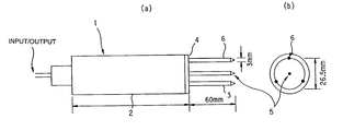
- FIG. 1 a is a front view showing diagrammatically an instrument for measurement by ADR;
- FIG. 1 b is a plan view of the instrument
- FIG. 2 is a graph showing the relationship between the output voltage of a sensor used in the measurement of the soil of SHIRASU pumice particles by ADR in Example 1 and its volumetric water content ⁇ ;
- FIG. 3 is an illustration showing diagrammatically the pressure-plate method used to measure the correlation between pF value and volumetric water content (moisture retention curve);
- FIG. 4 is an illustration showing diagrammatically the sand-column method used to measure a moisture retention curve
- FIGS. 5 a , 5 b and 5 c are graphs showing the relationship between volumetric water content and pF value for three mediums, a powder sample (FIG. 5 a ), a mixed sample (FIG. 5 b ) and a pumice sample (FIG. 5 c ); and
- FIG. 6 is a diagram showing an outline of the culture apparatus capable of automated irrigation control which was used in Example 3 of the invention.
- the methods of the invention are based on the idea of first measuring the volumetric soil water content and then determining its pF value from the measured volumetric soil water content.
- the water retentivity of the soil can be expressed by a variety of factors including the volumetric water content and the pF value.
- One method to measure the volumetric soil water content is gravimetry which involves collecting a sample of the soil to be measured and measuring the weight of the moisture in it.
- this method involving the measurement of a collected soil sample is not applicable in direct in situ measurement of the volumetric soil water content primarily because it does not permit continuous measurement.
- a method drawing increasing attention today as means for direct in situ measurement of the volumetric soil water content in a field is the electric pulse approach for measuring the dielectric constant of the soil. Measuring a certain area of the soil, this method experiences small enough variations in measured values and allows for simple and hence desired operations of measurement. In addition, very rapid measurement is possible, continuous measurement is easy to perform and high correlation is provided between the electrical output signal and the volumetric water content.
- the electric pulse approach can measure only the volumetric soil water content and no single means has been developed that relies upon this approach to determine the pF value which is an index for the moisture that is available to plants.
- TDR water has a relative dielectric constant of 81 which is by far greater than the values for soil solids (ca. 4) and air (1) and the empirical correlation established between the apparent relative dielectric constant of the soil and its water content is utilized to measure the volumetric soil water content.
- the dielectric constant of the soil is determined from the frequency domain characteristics of interfering reflected waves.
- TDR and FDR which can measure the volumetric soil water content are suitable for use in the method of the invention.
- ADR has recently been developed as a method that has comparable performance to TDR and FDR and which still allows for simpler measurement. This method is capable of simple and inexpensive measurement of the volumetric water conent through simple impedance measurement. Hence, ADR is more preferred for use in the present invention.
- ADR is similar to TDR and FDR in that the principle that the relative dielectric constant Ka of the soil is largely dependent on its volumetric water content ( ⁇ ) is used to determine ⁇ from the relation Ka ⁇ .
- ADR differs from TDR and FDR in that the relative dielectric constant Ka is determined by measuring the impedance (Z) of a transmission line over which radio-frequency electric pulses make a round trip via a probe in the soil.
- FIGS. 1 a and 1 b show diagrammatically an ADR operated, soil moisture sensor 1 in a front view (a) and a plan view (b), respectively.
- the sensor probe consists of a main body 2 and a sensor portion 3 ; the main body 2 contains a 100 MHz sinusoidal oscillator, a coaxial transmission line section and a measuring electronic circuit, and the sensor portion 3 consists of four parallel stainless steel rods.
- the center rod of the sensor portion 3 is a signal rod 5 around which three shield rods 6 are arranged to form an electric shield.
- the sensor portion acts as an additional section to the transmission line and has a value of Z which is substantially dependent on the dielectric constant of the soil within a circle 26.5 mm across that is surrounded by the shield rods 6 .
- the signal from the oscillator propagates over the transmission line through the sensor probe and if Z of the sensor portion 3 differs from Z of the coaxial transmission line in the main body, a certain amount of signal is reflected back from the junction 4 between the signal rod and the transmission line.
- the relative proportion of the reflected signal is called the reflection coefficient ⁇ .
- the reflection coefficient undergoes interference by the amplitude of the incident signal which is a cause of the voltage standing wave produced by the interference between the incident wave and the reflected wave, namely, the amplitude of the voltage measured over the length of the transmission line.
- the amplitude difference is represented by a relation as functions of the impedance of the transmission line and the impedance of the probe in the soil matrix.
- the amplitude of the voltage standing wave has such characteristics that it decreases with increasing soil moisture (increasing relative dielectric constant).
- the moisture content of the soil of interest is measured in a separate step by gravimetry or a like method and ADR or some other method is performed to yield an output signal value (e.g. output voltage); by performing repeated measurements at varying moisture contents of the soil, one can obtain a calibrated characteristic curve representing the relationship between the output voltage and the volumetric water content estimated from the soil moisture content and, as a result, one obtains means for providing the correct volumetric soil water content through ADR measurement in the field.
- the dielectric constant based methods enable the volumetric soil water content to be determined in a simple and easy way;
- ADR which is based on the measurement of average dielectric constant for the soil in a cylindrical portion of a specified diameter has a particular advantage in that the sensor probe need not be in intimate contact with the soil particles and that the volumetric water content can be measured even for soil which is composed of coarse particles such as pumice particles.
- the foregoing and following descriptions are directed to the method of determining the volumetric water content on the basis of a voltage output from an ADR instrument.
- the volumetric water content may be determined on the basis of other output signal values from the ADR instrument or it may be determined on the basis of output signal values from other sensor types such as a TDR and an FDR instrument.
- the volumetric soil water content obtained by these measurements namely, the soil moisture content includes bound water in the soil and other quantities of water not available to plants, so it differs from the pF value which is in good correspondence to the quantity of water that is available to plants.
- the result of measurement of the volumetric soil water content typically obtained by ADR is converted to the pF value of the soil.
- the matrix potential (pF value) of a soil sample and its volumetric water content are correlated by a characteristic curve depending on the texture of the soil and this curve is called a “moisture retention curve”.
- Known methods for measuring the moisture retention curve of a soil sample include the sand-column method, the suction method, the pressure-plate method and the pressure-membrane method.
- a specified pressure is applied to a soil sample and the weight of the soil at equilibrium is measured to determine the volumetric water content corresponding to the matrix potential; this procedure is repeated at various pressures to construct a moisture retention curve for the soil sample of interest.
- the sand-column method no pressure is applied to the soil sample but a specified position potential is applied by placing it on a sand column and a similar procedure of measurement is followed.
- the existence of a soil texture dependent correlation between the volumetric soil water content and its pF value is noted in the invention and after a moisture retention curve (correlation line) for the soil under analysis is preliminarily determined, the volumetric soil water content is determined by a suitable method such as ADR and the pF value of the soil is determined from the correlation line.
- the correlation line may be replaced by a conversion table or, if possible, by a mathematical approximation.
- a preferred means for determining the pF value of the soil from its volumetric water content by means of the correlation line is the use of a processor such as a microcomputer that is loaded with the predetermined correlation line plus a program for receiving an output signal from the ADR instrument and outputting a signal corresponding to the pF value of the soil.
- the characteristic technique of the invention which comprises the steps of constructing a characteristic line on the basis of an investigated correlation between the volumetric soil water content and its pF value, determining the volumetric soil water content on the basis of dielectric constant and determining the pF value of the soil from the determined volumetric water content on the basis of the preliminarily constructed characteristic line.
- pF values of the soil that correspond to various volume fractions of water in it and which provide basic data for the construction of a characteristic line correlating the volumetric water content and the pF value (i.e. a moisture retention curve) are determined by a method known in the art. Since the measurement of pF values requires great accuracy, an indoor method is employed. Known indoor methods for the measurement of pF values include the sand-column method, the pressure-plate method, the suction method, the pressure-membrane method and the vapor-pressure method. The sand column method is said to be suitable for the measurement at pF values in the range of 0.5-1.4 and the pressure-plate method at pF values in the range of 1.6-2.7.
- a method called the “centrifugation method” has been proposed for the measurement of pF values but this has not yet matured to a fully commercial stage. Therefore, one may well say that the pressure-plate method is the most suitable for the purpose of the invention, keeping the soil moisture content within the pF range of 1.7-2.7 where “easily available water” is found. However, other methods including the sand-column method can also be used in the invention.
- the pF values of the soil are typically measured by the pressure-plate method as follows.
- a pressure-plate apparatus 10 consists of a pressure chamber 12 and a pressure plate 13 .
- the pressure plate 13 consists of a porous ceramic plate 14 and a screen 15 fixed below which are covered with a rubber membrane 16 .
- the pressure chamber 12 is equipped with a pressure gage 18 to read the air pressure inside the chamber.
- a soil sample 11 is placed on top of the porous ceramic plate 14 saturated with water.
- air pressure is applied from a pressure source through a communicating pipe 17 , the soil water held at a potential greater than the matrix potential in equilibrium with the applied air pressure is depleted through the holes in the porous ceramic plate 14 .
- the soil water passes through a metal drain hole 19 , a pressure-resistant tube 20 and a drain port 21 in that order and then through a drain tube 23 having a pinch cock 22 to flow into a drain bin 24 .
- An evacuation valve 25 is provided in the interest of evacuating the pressure chamber 12 .
- the soil sample For each magnitude of the air pressure applied, the soil sample is taken out as it is placed on the pressure plate and its weight is measured.
- the moisture content of the soil sample is determined by calculating the difference between the weight of the measured soil sample and that of the same soil sample in a dry state.
- the determined moisture content corresponds to the applied air pressure, hence, the moisture potential at the time of measurement, thus providing a moisture content corresponding to a given pF value.
- a comparison table is constructed to provide a cross-reference between various pF values and the corresponding volume fractions of water.
- a moisture retention curve can be constructed in a graphical form from the values in the table by plotting the pF values on the horizontal axis and the volume fractions of water on the vertical axis.
- FIG. 4 is a diagrammatic representation of a sand-column apparatus generally indicated by 51 .
- sand grains that have passed through a sieve finer than 250 ⁇ m or quartz sand grains adjusted to have sizes between 300 and 180 ⁇ m are employed.
- Sand grains 52 preliminarily washed with water are packed into a column and a cock 60 is opened so that tap water 58 is flowed in at an inlet port 59 to saturate the sand grains.
- a support platform 61 and a brass screen 62 are fixed in the bottom of the column to retain the sand column.
- the sand column is vibrated by, for example, tapping on the sidewall so as to stabilize the arrangement of sand grains.
- the sand column is covered with a polyethylene sheet or lid 53 . It will be more effective if a soil sampling cylinder 54 is covered with such a lid.
- a soil sample (soil sampling cylinder) 54 is placed on the sand column 52 , the height of a movable water outlet 55 is fixed to the top end of the sand column and the soil sample 54 is saturated with water. Then, the movable water outlet 55 is lowered to a specified position and a cock 56 is opened to drain excess water 57 , whereby the level of the free water in the sand column is lowered to initiate dehydration of the soil sample.
- the water level L is read by a level meter 63 .
- the mass of the soil sample is measured to determine the volumetric water content of it.
- the matrix potential (cm) of the soil sample at that point in time is expressed as ⁇ (L+l/2) where l is the thickness of the soil sample.
- a moisture retention curve can be constructed in a graphical form from the values in the table by plotting the pF values on the horizontal axis and the volume fractions of water on the vertical axis.
- samples of the same soil with known volume fractions of water are subjected to measurement with, for example, an ADR instrument and its output signal values, for example, output voltages are measured to construct a calibrated table for converting the output voltage to the volumetric soil water content.
- an ADR instrument By plotting the data in a graphical form, the output voltage on the horizontal axis and the volumetric water content on the vertical axis, one obtains a characteristic line of the shape shown in FIG. 2 .
- the moisture content of the soil on site is determined using, for example, an ADR instrument.
- the volumetric soil water content is determined from the output voltage of the ADR instrument on the basis of the preliminarily constructed line characteristic line describing the correlation between the output voltage and the volumetric water content.
- the pF value of the oil can be determined from the determined volumetric soil water content on the basis of the preliminarily constructed moisture retention curve (the characteristic line describing the correlation between the volumetric water content and the pF value).
- the pF value of the soil can be calculated from the output voltage signal from the ADR instrument by means of an electronic circuit and the result is numerically presented on a display, thus realizing an extremely convenient measuring operation.
- the signal for the calculated pF value of the soil may be sent to a control circuit associated with an irrigation apparatus in order to activate a water supply device in the irrigation apparatus.
- the method of the invention enables the pF value of the soil to be measured directly and continuously in a by far convenient manner and the result of the measurement can be effectively used to control irrigation.
- mediums made of coarse particles having porous surfaces as exemplified by pumice particles have defied the measurement of pF values; according to the method of the invention, pF values can be determined if the volumetric soil water content is measured by ADR and other methods that are also applicable to porous mediums.
- the pressure-plate method, the sand-column method and various other methods that are used in the present invention to measure the correlation between the pF value and the volumetric water content are incapable of measurement on special soil and mediums, in particular, the soil (mediums) made of particles having porous surfaces.
- the reasons are as follows: if pumice particles with sizes of 1-5.6 mm are used as a medium, pressure application in the pressure-plate method does not guarantee the measurement of correct pF values since the water contained in the pumice particles does not form a continuous phase.
- the water contained in mediums such as the one made of pumice particles does not exist as a continuous phase and the resulting failure of capillary water to form continuous channels makes it impossible to measure the correct pF values.
- the water in the pumice medium does not form any liquid junction and there is no way to measure the correct pF values. Therefore, some special measures are necessary if soil composed of particles having porous surfaces is to be measured for pF values by the method of the present invention. This point will be discussed below in detail.
- the present inventors studied the feasibility of measuring the pF values of a pumice medium by the pressure-plate method or the sand-column method. As a result, it was found that the correct measurement of pF values was impossible with a medium sample solely composed of coarse particles whereas the intended measurement was possible with a mixture of two mediums, one composed of coarse particles and the other made of fine particles.
- the present inventors prepared three soil samples, one being a medium composed of coarse particles, the second being a fine particulate sample prepared by pulverizing the first sample, and the third being a mixed soil sample which was a dispersion of the first and second samples in admixture; the inventors measured the pF values of the second and third samples and found that the pF values of the first soil sample could be determined by subjecting the results of the measurements to the “subtraction operation” described below. This process is described below in detail.
- a coarse medium for example, a medium consisting of coarse pumice particles with sizes of 1-5.6 mm is provided. Then, this coarse particulate medium is pulverized to form a fine particulate medium. The coarse particulate medium and the fine particulate medium are mixed and dispersed to make a mixed soil sample.
- the two mediums are preferably mixed in equal weights but this is not the absolute requirement as long as the mixing weight ratio is double-checked.
- the relationship between the pF value and the volumetric water content is determined by the pressure-plate method or the like.
- the applicable procedure is described below.
- the medium solely composed of coarse pumice particles will be called sample B
- the fine particulate medium prepared from the coarse pumice particles will be called sample A
- the mixed soil sample prepared by mixing sample A with sample B will be called sample C
- the measurement of pF values by the pressure-plate method is given as an example.
- Sample A composed of the fine particulate medium can be measured for pF values by the pressure-plate method but sample B of coarse pumice particles cannot be measured for pF values by the pressure-plate method. Nevertheless, the mixed soil sample C can be measured for pF values. This is probably because the fine particles get into the gaps between the coarse particles to prevent blow-through. Therefore, the particle size of the fine particulate medium sample which is to be used to prepare the mixed soil sample is desirably such that the fine particles can get into the gaps between the coarse particles. Further, the fine particles should not be small enough to get into pores in the porous coarse particles. If the fine particles got into pores in the porous coarse particles, a behavioral change would occur to make it impossible to obtain the correct pF values. Generally, the particle size of the fine particulate sample is preferably, but not limited to, within the range of from about 50 to about 200 ⁇ m.
- the relationship between the pF value and the volumetric water content, namely, the moisture retention curve, is measured by the pressure-plate method. The measurement is repeated with the wetness of each sample being varied in several ways.
- volumetric water content of the mixed soil sample C at a given pF value is written as x c (v/v %) and if a given volume of the mixed soil sample has a moisture content of c (g), then the amount of water [c a (g)] held by the fine particles in the mixed soil sample is calculated by multiplying the moisture content [a (g)] of the same volume of fine particulate medium sample A at the stated pF value by the weight proportion of the fine particles in the mixed soil sample.
- the volumetric water content (v/v %) of the coarse particulate medium sample B can be determined from the calculated moisture content b (g) of the coarse particulate medium sample.
- the amounts of all samples are expressed in terms of weight.
- the coarse particles in the mixed soil sample have the surface water potential decreased if they are surrounded by the fine particles. However, owing to the porous nature of the coarse particles, this decrease in water potential is negligibly small since the surface area of the coarse particles that are surrounded by the fine particles is very small compared to the total surface area of the coarse particles (less than a hundredth of the latter).
- the thus determined volumetric water content of the coarse particulate medium sample may safely be considered to correspond to the pF value of the sample.
- the sand-column method is not capable of measuring the correct pF values of the coarse particulate sample since the water in the sample forms only interrupted liquid junctions.
- the fine particulate sample prepared by pulverizing the coarse particles as well as the mixed soil sample prepared by mixing the coarse particulate sample with this fine particulate sample can be correctly measured for pF values by the sand-column method. This is probably because the fine particles getting into the gaps between coarse particles help water form continuous liquid junctions.
- the sand-column method if it is modified by the above-described procedure, can be applied to a soil sample made of coarse particles such as pumice particles and yet it produces a moisture retention curve describing the relationship between the pF value and the volumetric water content of the soil sample.
- the method of the invention for measuring the pF value of the soil is implemented in different ways depending upon the nature of the soil.
- step (3) determine the pF value of the soil from the volumetric soil water content measured in step (2) on the basis of the moisture retention curve constructed in step (1).
- step (3) determine the pF value of the soil from the volumetric soil water content measured in step (2) on the basis of the moisture retention curve constructed in step (1).
- the pF value of the soil is determined by the above-described method of measuring its moisture content and irrigation of the soil is controlled on the basis of the determined pF value to realize cultivation of crops under optimum conditions. Specifically, the pF value of the soil is measured at given time intervals, each of the measured pF values is compared with the desired pF value, and the supply of irrigating water or the nutrient solution is controlled such that the pF value of the soil will not go outside the range of 1.7-2.7 which is optimal for crop cultivation.
- the desired pF value may be set at 2.0 and if the measured pF value is higher than this value, irrigating water or the nutrient solution is supplied but if the measured pF value is lower than the desired value, the supply of irrigating water or the nutrient solution is stopped.
- an apparatus for cultivation with a nutrient solution comprising a continuous drip applicator of a nutrient, means equipped with a nutrient flow valve for controlling the supply of the nutrient from the drip applicator, an instrument for measuring the volumetric water content of a medium, a processor which is loaded with a predetermined correlation between pF value and volumetric water content of the medium, which performs arithmetic operations for conversion to pF value from the volumetric water content of the medium as measured with the instrument for measuring the volumetric water content and which outputs a signal for the pF value of the medium on the basis of the result as outputted from the instrument for measuring the volumetric water content, and means for controlling the drip applicator by controlling the supply of the nutrient to the drip applicator on the basis of a signal for pF value as outputted from said processor.
- an apparatus for cultivation with a nutrient solution comprising a continuous drip applicator of a nutrient, means equipped with a nutrient flow valve for controlling the supply of the nutrient from the drip applicator, an ADR instrument having a probe to be inserted into a medium, a processor which is loaded with two predetermined correlations for the medium, one being between pF value and volumetric water content and the other being between the output voltage from the ADR instrument and the volumetric water content, which performs arithmetic operations for conversion from the output voltage of the ADR instrument to the volumetric water content of the medium and for conversion to pF value from the volumetric water content of the medium and which outputs a signal for the pF value of the medium on the basis of the output voltage of the ADR instrument, and means for controlling the drip applicator by controlling the supply of the nutrient to the drip applicator on the basis of a signal for pF value as outputted from said processor.
- the above-described method for controlling irrigation may be implemented by an apparatus for cultivation with a nutrient solution on a solid medium which comprises a continuous drip applicator of a nutrient, an ADR instrument having a probe to be inserted into a medium and control means for controlling the supply of the nutrient to the drip applicator in response to the output voltage from said ADR instrument and which is timer-controlled to operate in response to the output voltage from the ADR instrument at given time intervals.
- the means for controlling the drip applicator is preferably designed as follows: the processor is loaded with two predetermined correlations for the medium of interest, one being between pF value and volumetric water content and the other being between the output voltage from the ADR instrument and the volumetric water content, and the processor performs arithmetic operations for conversion from the output voltage of the ADR instrument to the volumetric water content of the medium and for conversion to pF value from the volumetric water content of the medium and outputs a signal for the pF value of the medium on the basis of the output voltage of the ADR instrument, and the supply of the nutrient to the drip applicator is controlled on the basis of the signal for pF value outputted from said processor.
- the period at which the degree of opening of the nutrient flow valve is adjusted on the basis of a measured pF value depends on the required strictness in control, which in turn depends on the kind of crop to be cultivated; generally speaking, the supply of irrigating solution or the nutrient is controlled at an interval of 10 minutes to 2 hours, preferably at an interval of 10-20 minutes, on the basis of the measured pF value.
- the volumetric water content is measured by ADR; however, as already mentioned, the TDR instrument, the FDR instrument and other types of instrument may also be used as long as they can measure the volumetric water content on the basis of the dielectric constant. It should also be noted that the dielectric constant based technique is not the sole method that can be used to measure the volumetric soil water content and any methods can be used in the invention as long as they are capable of direct measurement of the volumetric soil water content in a field.
- the soil whose pF value can be measured by the method of the invention may be exemplified by not only the so-called “soil” described above but also porous mediums including pumice and charcoal.
- the medium made of pumice precise measurement can be accomplished even if it is made of SHIRASU pumice.
- SHIRASU pumice is the generic name for “non-fused portions of the deposits of pyroclastic pumice flows ejected from large caldera volcanos in the late Pleistocene, or secondary deposits of such portions”.
- SHIRASU from the southern part of Kyushu is famous.
- SHIRASU of the same nature is also distributed around Lake Kussharo, Lake Shikotsu, Lake Toya and Lake Towada, as well as around caldera volcanos such as Mt. okachidake and Mt. Aso.
- SHIRASU is shown as the deposits of pumice flows.
- Examples of the crops that can be cultivated by the method of the invention with nutrient solutions include the following: vegetable fruits such as tomato, cherry tomato, cucumber, eggplant, pimento, paprika, (jumbo green pepper), okra, kidney bean, garden pea, bitter gourd, luffa, watermelon and melon; leaf vegetables such as corn salad, spinach, Brassica Rapa var.
- a sample of SHIRASU pumice (product of Kagoshima Prefecture, Kyushu, Japan) having particle sizes in the range of 1-5.6 mm was assayed by ADR with its wetness being varied to investigate the relationship between the output voltage of the ADR instrument and the volumetric water content of the pumice medium.
- the output voltage of the ADR instrument was plotted in a graphical form on the horizontal axis and the volumetric water content on the vertical axis to construct a curve of the shape shown in FIG. 2 .
- Two soil samples were provided, one being a sample of SHIRASU pumice (product of Kagoshima Prefecture, Kyushu, Japan) having particle sizes in the range of 1-5.6 mm and the other being a fine particulate pumice sample that was prepared by pulverizing the SHIRASU pumice to particle sizes in the range of about 50-200 ⁇ m.
- the two samples each measuring 100 ml, had different weights; the pumice sample weighed 53 g and the fine particulate pumice sample 79.4 g.
- the two samples were mixed in nearly equal weights to prepare a mixed soil sample.
- a hundred milliliters of the mixed soil sample weighed 72.5 g and it consisted of 35.2 g of the pumice sample and 37.3 g of the fine particulate pumice sample.
- the mixed soil sample was measured for the volumetric water content at various pF values by the pressure-plate method.
- the fine particulate pumice sample was measured for the volumetric water content at various pF values by the pressure-plate method.
- the two measurements were repeated with the wetness of the samples varied in several ways.
- the pressure-plate method was used to measure pF values because the range of pF values that could be measured by the pressure-plate method were in good agreement with the range of pF values held as a suitable condition for the actual cultivation.
- the mixed sample M had a pF value of 1.6 when its volumetric water content was 44.8 (v/v %).
- the fine particulate pumice sample P had a volumetric water content of 53.3 (v/v %).
- the moisture content (g) of the fine particulate pumice component in the mixed sample M By subtracting the moisture content (g) of the fine particulate pumice component in the mixed sample M from the moisture content (g) of the mixed sample, one can determine the moisture content of the pumice component in the mixed sample, from which one can calculate the volumetric water content of the pumice sample.
- the moisture content [A3] in 100 ml of the mixed sample M is found to be 44.8 g from its volumetric water content [A2].
- Example 2 Looking at the relationship between the pF value of the pumice sample and its volumetric water content that is shown graphically in FIG. 5 c , one can see the following: the method of Example 2 is not fully applicable within the pF range of 1.6-2.0 since the curve is substantially flat; on the other hand, a certain correlation was found to exist between the pF value and the volumetric water content in the pF range of 2.0-2.7 and could be effectively used as an index for controlling the irrigation of mediums.
- Example 2 Using the moisture retention curve obtained in Example 2, one can easily convert the values of ADR based volumetric water content in Example 2 to the pF values of the medium that needs to be controlled for irrigation.
- Corn salad was cultivated on a medium of SHIRASU pumice (product of Kagoshima Prefecture, Kyushu, Japan) having particle sizes in the range of 1-5.6 mm.
- a plurality of cell trays were provided and one seed of corn salad was sown on each tray. After 21 days of nursing, the seedlings were transplanted to a leaf vegetable cultivation bed for setting at a density of 42 plants per square meter. The planted area was 4 m 2 .
- corn salad was cultivated by repeating the procedure of Example 3 except that irrigation was timer controlled to take place twice a day, at 9 o'clock in the morning and 3 o'clock in the afternoon, and continued until excess nutrient came out of the cultivation bed.
- the yield was 2694 g/m 2 .
- the nutrient was used in a volume of 148.6 L/m 2 .
- a mold-like growth became visible on the surface of the cultivation bed, indicating that the nutrient had been supplied in an amount more than necessary for the actual growth of corn salad.
- Example 3 Comparing Example 3 with Comparative Example 1, one can see that the cultivation using the invention method of irrigation control could achieve a higher yield using a smaller amount of nutrient than when the conventional timer-controlled method of irrigation was adopted.
- the amount of a nutrient can be controlled precisely such that it is supplied in the quantity actually required by the crop being cultivated and this helps prevent the nutrient from being supplied in excess amount that is simply wasted as liquid emissions and the like.
- the pF value of the soil can be measured by a simple method without using the conventional tensiometer. Since this measurement can be achieved by ADR and other convenient methods, a simple and convenient apparatus will suffice and reproducible data are obtained to permit simple measurements in ordinary fields.
- the conventional methods such as the pressure-plate method have been incapable of correctly measuring the moisture retention curve which describes the correlation between the pF value and the volumetric water content. This is not the case in the preferred aspect of the invention and even with a coarse particulate soil sample, the correct moisture retention curve can be determined by the pressure-plate method and the like and the pF value of such soil can be measured in a simple way. Hence, regardless of soil texture, soil management can be easily performed to prevent drying of the soil or realize irrigation.
- the invention also enables the supply of nutrients to be controlled on the basis of pF value in cultivation on solid mediums and the nutrient can be supplied in amounts that keep pace with the growth of the crop being cultivated, contributing to a higher yield of the crop. Since the pF value can be controlled automatically, the intended control is easy to achieve requiring no manpower, thus contributing to labor saving.
- the present invention is very effective for the purpose of preserving environmental resources.
- the water required for cultivation can be reduced to a minimum amount whereas the fertilizer can be utilized to the fullest extent; hence, only a small amount of fertilizer will be discharged unabsorbed, reducing the likelihood of eutrophication of water bodies and profuse growth of algae due to wastewater.
- Continuous drip irrigation on the rock wool medium is extensively practiced today in crop cultivation but the spent rock wool medium has been found to cause an extremely serious problem as an industrial waste.
- Another crucial problem is the liquid emission due to excessive supply of the nutrient. Using the pumice medium and adopting the invention method for irrigation control, one can solve the two problems simultaneously and this is indeed a great benefit from the viewpoint of protecting both resources and the environment.
Landscapes
- Life Sciences & Earth Sciences (AREA)
- Physics & Mathematics (AREA)
- Health & Medical Sciences (AREA)
- Chemical & Material Sciences (AREA)
- Engineering & Computer Science (AREA)
- Pathology (AREA)
- General Health & Medical Sciences (AREA)
- General Physics & Mathematics (AREA)
- Immunology (AREA)
- Analytical Chemistry (AREA)
- Biochemistry (AREA)
- Electromagnetism (AREA)
- Environmental Sciences (AREA)
- Water Supply & Treatment (AREA)
- Soil Sciences (AREA)
- Environmental & Geological Engineering (AREA)
- General Life Sciences & Earth Sciences (AREA)
- Geology (AREA)
- Remote Sensing (AREA)
- Food Science & Technology (AREA)
- Medicinal Chemistry (AREA)
- Investigating Or Analyzing Materials By The Use Of Electric Means (AREA)
- Cultivation Of Plants (AREA)
Applications Claiming Priority (3)
| Application Number | Priority Date | Filing Date | Title |
|---|---|---|---|
| JP36469399 | 1999-12-22 | ||
| JP11-364693 | 1999-12-22 | ||
| PCT/JP2000/009090 WO2001046681A1 (fr) | 1999-12-22 | 2000-12-21 | Procede de mesure de la valeur pf d'un sol, et procede de commande d'irrigation et dispositif de commande d'irrigation |
Publications (2)
| Publication Number | Publication Date |
|---|---|
| US20030024155A1 US20030024155A1 (en) | 2003-02-06 |
| US6719488B2 true US6719488B2 (en) | 2004-04-13 |
Family
ID=18482440
Family Applications (1)
| Application Number | Title | Priority Date | Filing Date |
|---|---|---|---|
| US10/149,432 Expired - Fee Related US6719488B2 (en) | 1999-12-22 | 2000-12-21 | Soil pf value measuring method, and irrigation control method and irrigation control device |
Country Status (7)
| Country | Link |
|---|---|
| US (1) | US6719488B2 (zh) |
| JP (1) | JP3782732B2 (zh) |
| KR (1) | KR100807675B1 (zh) |
| CN (2) | CN1230673C (zh) |
| AU (1) | AU2400001A (zh) |
| TW (1) | TW466343B (zh) |
| WO (1) | WO2001046681A1 (zh) |
Cited By (7)
| Publication number | Priority date | Publication date | Assignee | Title |
|---|---|---|---|---|
| US20040153264A1 (en) * | 2003-02-05 | 2004-08-05 | Stanley Teich | Automatic wire dielectric analyzer |
| US20050044782A1 (en) * | 1999-10-19 | 2005-03-03 | Ebara Corporation | Culture medium |
| US20110036155A1 (en) * | 2004-12-29 | 2011-02-17 | Rain Bird Corporation | Soil Moisture Sensor and Controller |
| US20110273196A1 (en) * | 2005-02-04 | 2011-11-10 | Jason Lester Hill | Long Range, Battery Powered, Wireless Environmental Sensor Interface Devices |
| US20120060588A1 (en) * | 2010-09-10 | 2012-03-15 | The Hong Kong University Of Science And Technology | Humidity and osmotic suction-controlled box |
| US20220386543A1 (en) * | 2021-06-04 | 2022-12-08 | Groupe Ramo Inc. | Controlled irrigation process and system for land application of wastewater |
| EP4279918A1 (fr) | 2022-05-18 | 2023-11-22 | Urbansense | Procede de suivi de l'humidite d'un sol, station et installation de mesure d'humidite d'un sol |
Families Citing this family (32)
| Publication number | Priority date | Publication date | Assignee | Title |
|---|---|---|---|---|
| US7189678B2 (en) | 2002-03-05 | 2007-03-13 | Antonio Danilo Lobato Salinas | Method for the recuperation of decayed agricultural plantations |
| US7068051B2 (en) * | 2003-02-19 | 2006-06-27 | Technical Development Consultants, Inc. | Permittivity monitor uses ultra wide band transmission |
| GB2411245B (en) * | 2004-02-19 | 2007-06-06 | Devon & Exeter Steeplechases L | Turf condition meter |
| US7228900B2 (en) * | 2004-06-15 | 2007-06-12 | Halliburton Energy Services, Inc. | System and method for determining downhole conditions |
| EP1707048A1 (en) * | 2005-04-01 | 2006-10-04 | Wavin B.V. | A method of operating a percolation system for waste water as well as a percolation system for carrying out the method |
| CH701209A1 (de) * | 2009-06-03 | 2010-12-15 | Plantcare Ag | Mobile vorrichtung und verfahren zur bedarfsgerechten bewässerung eines bodens. |
| IN2012DN02310A (zh) * | 2009-09-03 | 2015-08-21 | Rubicon Res Pty Ltd | |
| JP2012194027A (ja) * | 2011-03-16 | 2012-10-11 | Kett Electric Laboratory | 水分含有材の水分測定装置及び該水分測定装置を使用した水分測定方法 |
| EP2729308B1 (en) * | 2011-06-30 | 2017-10-11 | 3M Innovative Properties Company | Apparatus and method for microcontact printing on indefinite length webs |
| KR101246808B1 (ko) * | 2011-08-24 | 2013-03-26 | 채원식 | 토성 변화 시뮬레이션 시스템 |
| JP5999595B2 (ja) * | 2011-09-16 | 2016-09-28 | 国立研究開発法人農業・食品産業技術総合研究機構 | かん水制御装置及びかん水制御方法 |
| CN102393320A (zh) * | 2011-09-21 | 2012-03-28 | 中国科学院武汉岩土力学研究所 | 一种不同含水率岩石试验样品的制备方法 |
| KR101330828B1 (ko) | 2012-06-25 | 2013-11-18 | (주)한국케트 | 콘크리트의 함수량을 측정하기 위한 수분함량측정기 |
| JP5615462B1 (ja) * | 2012-11-19 | 2014-10-29 | 東洋ゴム工業株式会社 | 人工土壌培地 |
| CN103053386B (zh) * | 2012-12-13 | 2014-08-13 | 宁波大叶园林工业有限公司 | 一种智能定时器 |
| KR20150083915A (ko) * | 2012-12-28 | 2015-07-20 | 도요 고무 고교 가부시키가이샤 | 인공 토양 단립체, 및 인공 토양 배지 |
| JP5692826B2 (ja) * | 2013-06-06 | 2015-04-01 | キャビノチェ株式会社 | 土壌用水分インジケータ |
| RU2632980C2 (ru) | 2013-07-05 | 2017-10-11 | Роквул Интернэшнл А/С | Система выращивания растений |
| US9909987B1 (en) | 2014-07-30 | 2018-03-06 | Transcend Engineering and Technology, LLC | Systems, methods, and software for determining spatially variable distributions of the dielectric properties of a material |
| US9970969B1 (en) | 2014-08-26 | 2018-05-15 | Transcend Engineering and Technology, LLC | Systems, methods, and software for determining spatially variable distributions of the dielectric properties of a heterogeneous material |
| CN105973951A (zh) * | 2016-07-04 | 2016-09-28 | 中国环境科学研究院 | 一种堆肥物料含水量测定探针及监测装置和监测系统 |
| CN106645314B (zh) * | 2016-12-29 | 2023-10-03 | 中环天仪(天津)气象仪器有限公司 | 用于fdr管式土壤水分传感器故障诊断装置及检测方法 |
| KR101876101B1 (ko) * | 2016-12-30 | 2018-07-06 | 박대성 | 수목 생육 모니터링 시스템 및 이를 이용한 수목 생육 모니터링 방법 |
| KR101908041B1 (ko) * | 2017-06-23 | 2018-10-16 | 제이스테판 주식회사 | 절단력이 조절되는 동력클러치 및 이를 구비한 프린터 |
| US10257974B1 (en) * | 2017-09-22 | 2019-04-16 | Cnh Industrial America Llc | Seed meter with multiple sensors for seed cell status monitoring |
| AU2019212212B2 (en) * | 2018-01-23 | 2024-05-02 | Dennis M. Anderson | Analysis of porous material using laboratory calibrated test apparatus and sample data |
| KR102420701B1 (ko) * | 2019-08-20 | 2022-07-14 | 주식회사 제이디테크 | 토양 측정 기반의 스마트팜 운용 시스템 |
| WO2021056114A1 (en) * | 2019-09-27 | 2021-04-01 | Hortau Inc. | Systems and methods for monitoring and controlling crop irrigation schedules |
| TWI706716B (zh) | 2019-11-29 | 2020-10-11 | 國立勤益科技大學 | 智慧水霧耕作物監控培植系統 |
| JP7348652B2 (ja) * | 2020-02-04 | 2023-09-21 | 国立研究開発法人農業・食品産業技術総合研究機構 | 演算方法、演算装置、および演算プログラム |
| WO2023223413A1 (ja) * | 2022-05-17 | 2023-11-23 | 日本電信電話株式会社 | 腐食推定装置および方法 |
| CN115843635B (zh) * | 2022-11-30 | 2023-06-16 | 中国农业科学院农业资源与农业区划研究所 | 一种稻田灌排单元面源污染与甲烷协同减排方法 |
Citations (6)
| Publication number | Priority date | Publication date | Assignee | Title |
|---|---|---|---|---|
| JPH01317342A (ja) | 1987-11-30 | 1989-12-22 | Sumitomo Electric Ind Ltd | 自動灌水制御装置 |
| JPH07244040A (ja) | 1994-03-07 | 1995-09-19 | Asia Kosoku Kk | 土壌水分測定方法および装置 |
| WO1997009590A2 (en) | 1995-08-30 | 1997-03-13 | Purdue Research Foundation | Soil moisture or dielectric constant measuring system |
| JPH09271276A (ja) | 1996-04-09 | 1997-10-21 | Tsutomu Nishide | 土壌潅水指示装置及びその方法 |
| JPH1078401A (ja) | 1996-09-02 | 1998-03-24 | Nas Toa Co Ltd | Pf値測定器ユニット及びpf値測定器ユニットを備えた緑化用培器システム |
| US5898310A (en) * | 1996-07-23 | 1999-04-27 | Liu; Jin-Chen | Device and method for determining properties of a soil |
Family Cites Families (2)
| Publication number | Priority date | Publication date | Assignee | Title |
|---|---|---|---|---|
| US4852802A (en) * | 1988-08-08 | 1989-08-01 | Jerry Iggulden | Smart irrigation sprinklers |
| CN2150714Y (zh) * | 1993-01-19 | 1993-12-29 | 江苏省农业科学院 | 一种节水自动补水器 |
-
2000
- 2000-12-21 JP JP2001547538A patent/JP3782732B2/ja not_active Expired - Fee Related
- 2000-12-21 CN CNB008171351A patent/CN1230673C/zh not_active Expired - Fee Related
- 2000-12-21 CN CNB2005100651107A patent/CN100437095C/zh not_active Expired - Fee Related
- 2000-12-21 KR KR1020027007429A patent/KR100807675B1/ko not_active IP Right Cessation
- 2000-12-21 US US10/149,432 patent/US6719488B2/en not_active Expired - Fee Related
- 2000-12-21 TW TW089127576A patent/TW466343B/zh not_active IP Right Cessation
- 2000-12-21 WO PCT/JP2000/009090 patent/WO2001046681A1/ja active Application Filing
- 2000-12-21 AU AU24000/01A patent/AU2400001A/en not_active Abandoned
Patent Citations (6)
| Publication number | Priority date | Publication date | Assignee | Title |
|---|---|---|---|---|
| JPH01317342A (ja) | 1987-11-30 | 1989-12-22 | Sumitomo Electric Ind Ltd | 自動灌水制御装置 |
| JPH07244040A (ja) | 1994-03-07 | 1995-09-19 | Asia Kosoku Kk | 土壌水分測定方法および装置 |
| WO1997009590A2 (en) | 1995-08-30 | 1997-03-13 | Purdue Research Foundation | Soil moisture or dielectric constant measuring system |
| JPH09271276A (ja) | 1996-04-09 | 1997-10-21 | Tsutomu Nishide | 土壌潅水指示装置及びその方法 |
| US5898310A (en) * | 1996-07-23 | 1999-04-27 | Liu; Jin-Chen | Device and method for determining properties of a soil |
| JPH1078401A (ja) | 1996-09-02 | 1998-03-24 | Nas Toa Co Ltd | Pf値測定器ユニット及びpf値測定器ユニットを備えた緑化用培器システム |
Non-Patent Citations (8)
| Title |
|---|
| American Geophysical Union, Water Resources Research, vol. 16, Jun. 1980, Nov. 3, pp. 574-582. |
| Dojo Kankyo Burnsekiho, Analysis of Soil Environement, 1997, pp. 48-65 (w/partial English Translation). |
| Dojo Shindan no Hoho to Katsuyo, Soil Analysis-Methods and Aplications, 1996, pp. 72-77. |
| Haruhiko Horino and Toshisuke Maruyama, TDR Measurment of Soil Moisture with Three-Line Probe, Collected Papers of Japanese Society of Irrigation, Drainage and Reclamation Engineering, 1993, pp. 168, 119-120. |
| Kitahei Tatsumi et al, Field Measurement of Soil Moisture By FDR, Collected Papers of Japanese Society of Irrigation, Drainage and Reclamation Engineering, 1996, No. 182, pp. 31-38. |
| Makoto Nakajima et al, Proceedings of 1997 Spring Meeting of Japanese Association of Groundwater Hydrology, 1997, pp. 18-23. |
| Saishin Dojogaku, Modern Soil Science, 1977, pp. 101-107 (w/partial English Translation). |
| Tsuchi no Kankyoken, Environment of Soil, 1997, pp. 30-32, 72-76. |
Cited By (14)
| Publication number | Priority date | Publication date | Assignee | Title |
|---|---|---|---|---|
| US20050044782A1 (en) * | 1999-10-19 | 2005-03-03 | Ebara Corporation | Culture medium |
| US7031856B2 (en) * | 2003-02-05 | 2006-04-18 | Northrop Grumman Corporation | Automatic wire dielectric analyzer |
| US20040153264A1 (en) * | 2003-02-05 | 2004-08-05 | Stanley Teich | Automatic wire dielectric analyzer |
| US8671969B2 (en) | 2004-12-29 | 2014-03-18 | Rain Bird Corporation | Soil moisture sensor and controller |
| US20110036155A1 (en) * | 2004-12-29 | 2011-02-17 | Rain Bird Corporation | Soil Moisture Sensor and Controller |
| US8104498B2 (en) | 2004-12-29 | 2012-01-31 | Rain Bird Corporation | Soil moisture sensor and controller |
| US10085393B2 (en) * | 2005-02-04 | 2018-10-02 | The Toro Company | Long range, battery powered, wireless environmental sensor interface devices |
| US20110273196A1 (en) * | 2005-02-04 | 2011-11-10 | Jason Lester Hill | Long Range, Battery Powered, Wireless Environmental Sensor Interface Devices |
| US20120060588A1 (en) * | 2010-09-10 | 2012-03-15 | The Hong Kong University Of Science And Technology | Humidity and osmotic suction-controlled box |
| US8800353B2 (en) * | 2010-09-10 | 2014-08-12 | The Hong Kong University Of Science And Technology | Humidity and osmotic suction-controlled box |
| US20220386543A1 (en) * | 2021-06-04 | 2022-12-08 | Groupe Ramo Inc. | Controlled irrigation process and system for land application of wastewater |
| US11856901B2 (en) * | 2021-06-04 | 2024-01-02 | Groupe Ramo Inc. | Controlled irrigation process and system for land application of wastewater |
| EP4279918A1 (fr) | 2022-05-18 | 2023-11-22 | Urbansense | Procede de suivi de l'humidite d'un sol, station et installation de mesure d'humidite d'un sol |
| FR3135590A1 (fr) | 2022-05-18 | 2023-11-24 | Urbasense | Procede de suivi de l’humidite d’un sol, station et installation de mesure d’humidite d’un sol |
Also Published As
| Publication number | Publication date |
|---|---|
| CN1230673C (zh) | 2005-12-07 |
| JP3782732B2 (ja) | 2006-06-07 |
| CN1409819A (zh) | 2003-04-09 |
| WO2001046681A1 (fr) | 2001-06-28 |
| AU2400001A (en) | 2001-07-03 |
| US20030024155A1 (en) | 2003-02-06 |
| CN100437095C (zh) | 2008-11-26 |
| TW466343B (en) | 2001-12-01 |
| KR20020060997A (ko) | 2002-07-19 |
| KR100807675B1 (ko) | 2008-03-03 |
| CN1690699A (zh) | 2005-11-02 |
Similar Documents
| Publication | Publication Date | Title |
|---|---|---|
| US6719488B2 (en) | Soil pf value measuring method, and irrigation control method and irrigation control device | |
| Toumi et al. | Performance assessment of AquaCrop model for estimating evapotranspiration, soil water content and grain yield of winter wheat in Tensift Al Haouz (Morocco): Application to irrigation management | |
| Fares et al. | Advances in crop water management using capacitive water sensors | |
| Tanner | Measurement of evapotranspiration | |
| Fares et al. | Evaluation of capacitance probes for optimal irrigation of citrus through soil moisture monitoring in an entisol profile | |
| Arndt | The impedance of soil seals and the forces of emerging seedlings | |
| Abrisqueta et al. | Basal crop coefficients for early-season peach trees | |
| Ley | Soil water monitoring & measurement | |
| Sample et al. | Understanding soil moisture sensors: A fact sheet for irrigation professionals in Virginia | |
| JP3992939B2 (ja) | 屋上及び地上緑化システム用灌水制御装置 | |
| Payet et al. | Modelling the fate of nitrogen following pig slurry application on a tropical cropped acid soil on the island of Réunion (France) | |
| Verhoef et al. | Soil water and its management | |
| Gamble et al. | Ecohydrology of irrigated silage maize and alfalfa production systems in the upper midwest US | |
| Snyder et al. | Irrigation scheduling | |
| Gill | Temporal variability of soil hydraulic properties under different soil management practices | |
| Macelloni et al. | Microwave radiometric measurements of soil moisture in Italy | |
| Teixeira et al. | Soil water. | |
| Nolz | Performance assessment of selected devices for monitoring soil water balance components with respect to agricultural water management | |
| Singh | Modeling root water uptake of cotton (Gossypium hirsutum l.) under deficit subsurface drip irrigation in West Texas | |
| Amini et al. | Determination of water requirement and crop coefficient for strawberry using lysimeter experiment in a semi-arid climate | |
| Abubaker | Irrigation scheduling for efficient water use in dry climates | |
| Stofberg | The effect of irrigation scheduling on the performance of young apple trees in newly established orchards | |
| Waller et al. | Physical characterization of greenhouse substrates for automated irrigation management | |
| Bellamy | Sensor-based soil water monitoring to more effectively manage agricultural water resources in coastal plain soils | |
| Oweis | An integrated approach for the estimation of crop water requirements based on soil, plant and atmospheric measurements N. Jovanovic, S. Dzikiti and M. Gush, Council for Scientific and Industrial Research (CSIR), South Africa |
Legal Events
| Date | Code | Title | Description |
|---|---|---|---|
| AS | Assignment |
Owner name: EBARA CORPORATION, JAPAN Free format text: ASSIGNMENT OF ASSIGNORS INTEREST;ASSIGNORS:KURODA, TETSUO;OTSUKA, HIDEMITSU;KAMIYA, ICHIRO;AND OTHERS;REEL/FRAME:013053/0731 Effective date: 20020607 |
|
| FEPP | Fee payment procedure |
Free format text: PAYOR NUMBER ASSIGNED (ORIGINAL EVENT CODE: ASPN); ENTITY STATUS OF PATENT OWNER: LARGE ENTITY Free format text: PAYER NUMBER DE-ASSIGNED (ORIGINAL EVENT CODE: RMPN); ENTITY STATUS OF PATENT OWNER: LARGE ENTITY |
|
| FPAY | Fee payment |
Year of fee payment: 4 |
|
| REMI | Maintenance fee reminder mailed | ||
| LAPS | Lapse for failure to pay maintenance fees | ||
| STCH | Information on status: patent discontinuation |
Free format text: PATENT EXPIRED DUE TO NONPAYMENT OF MAINTENANCE FEES UNDER 37 CFR 1.362 |
|
| FP | Lapsed due to failure to pay maintenance fee |
Effective date: 20120413 |