US6706633B2 - Method of forming a self-aligned contact pad for use in a semiconductor device - Google Patents
Method of forming a self-aligned contact pad for use in a semiconductor device Download PDFInfo
- Publication number
- US6706633B2 US6706633B2 US10/115,430 US11543002A US6706633B2 US 6706633 B2 US6706633 B2 US 6706633B2 US 11543002 A US11543002 A US 11543002A US 6706633 B2 US6706633 B2 US 6706633B2
- Authority
- US
- United States
- Prior art keywords
- layer
- interlayer insulating
- insulating layer
- forming
- gate
- Prior art date
- Legal status (The legal status is an assumption and is not a legal conclusion. Google has not performed a legal analysis and makes no representation as to the accuracy of the status listed.)
- Expired - Lifetime
Links
- 238000000034 method Methods 0.000 title claims abstract description 60
- 239000004065 semiconductor Substances 0.000 title claims abstract description 40
- 239000010410 layer Substances 0.000 claims abstract description 170
- 239000011229 interlayer Substances 0.000 claims abstract description 43
- 239000000758 substrate Substances 0.000 claims abstract description 29
- 239000004020 conductor Substances 0.000 claims abstract description 22
- 125000006850 spacer group Chemical group 0.000 claims abstract description 4
- 150000004767 nitrides Chemical class 0.000 claims description 41
- 229910021420 polycrystalline silicon Inorganic materials 0.000 claims description 29
- 229920005591 polysilicon Polymers 0.000 claims description 29
- 239000002002 slurry Substances 0.000 claims description 20
- 238000005530 etching Methods 0.000 claims description 16
- WQJQOUPTWCFRMM-UHFFFAOYSA-N tungsten disilicide Chemical compound [Si]#[W]#[Si] WQJQOUPTWCFRMM-UHFFFAOYSA-N 0.000 claims description 9
- 229910021342 tungsten silicide Inorganic materials 0.000 claims description 9
- 238000005498 polishing Methods 0.000 claims description 3
- 239000000126 substance Substances 0.000 claims description 3
- 230000007547 defect Effects 0.000 description 7
- 239000012535 impurity Substances 0.000 description 4
- 238000007796 conventional method Methods 0.000 description 2
- 238000002955 isolation Methods 0.000 description 2
- 238000000151 deposition Methods 0.000 description 1
- 238000001312 dry etching Methods 0.000 description 1
- 238000009413 insulation Methods 0.000 description 1
- 229920002120 photoresistant polymer Polymers 0.000 description 1
Images


Classifications
-
- H—ELECTRICITY
- H01—ELECTRIC ELEMENTS
- H01L—SEMICONDUCTOR DEVICES NOT COVERED BY CLASS H10
- H01L21/00—Processes or apparatus adapted for the manufacture or treatment of semiconductor or solid state devices or of parts thereof
- H01L21/70—Manufacture or treatment of devices consisting of a plurality of solid state components formed in or on a common substrate or of parts thereof; Manufacture of integrated circuit devices or of parts thereof
- H01L21/71—Manufacture of specific parts of devices defined in group H01L21/70
- H01L21/768—Applying interconnections to be used for carrying current between separate components within a device comprising conductors and dielectrics
- H01L21/76897—Formation of self-aligned vias or contact plugs, i.e. involving a lithographically uncritical step
-
- H—ELECTRICITY
- H01—ELECTRIC ELEMENTS
- H01L—SEMICONDUCTOR DEVICES NOT COVERED BY CLASS H10
- H01L21/00—Processes or apparatus adapted for the manufacture or treatment of semiconductor or solid state devices or of parts thereof
- H01L21/02—Manufacture or treatment of semiconductor devices or of parts thereof
- H01L21/04—Manufacture or treatment of semiconductor devices or of parts thereof the devices having potential barriers, e.g. a PN junction, depletion layer or carrier concentration layer
- H01L21/18—Manufacture or treatment of semiconductor devices or of parts thereof the devices having potential barriers, e.g. a PN junction, depletion layer or carrier concentration layer the devices having semiconductor bodies comprising elements of Group IV of the Periodic Table or AIIIBV compounds with or without impurities, e.g. doping materials
- H01L21/28—Manufacture of electrodes on semiconductor bodies using processes or apparatus not provided for in groups H01L21/20 - H01L21/268
-
- H—ELECTRICITY
- H01—ELECTRIC ELEMENTS
- H01L—SEMICONDUCTOR DEVICES NOT COVERED BY CLASS H10
- H01L21/00—Processes or apparatus adapted for the manufacture or treatment of semiconductor or solid state devices or of parts thereof
- H01L21/70—Manufacture or treatment of devices consisting of a plurality of solid state components formed in or on a common substrate or of parts thereof; Manufacture of integrated circuit devices or of parts thereof
- H01L21/71—Manufacture of specific parts of devices defined in group H01L21/70
- H01L21/768—Applying interconnections to be used for carrying current between separate components within a device comprising conductors and dielectrics
- H01L21/76838—Applying interconnections to be used for carrying current between separate components within a device comprising conductors and dielectrics characterised by the formation and the after-treatment of the conductors
- H01L21/76895—Local interconnects; Local pads, as exemplified by patent document EP0896365
Definitions
- the present invention relates to a semiconductor device. More particularly, the present invention relates to a method of forming a self-aligned contact pad for use in a semiconductor device.
- a bar-type self-aligned contact (SAC) process is used in a method for forming a direct contact (DC) pad and a bit line contact (BC) pad instead of a more conventional hole-type SAC.
- the method for forming a DC pad and a BC pad additionally includes a chemical mechanical polishing (CMP) process to increase a process margin.
- CMP chemical mechanical polishing
- a conventional method for forming a self-aligned contact pad includes depositing a polysilicon layer, etching back the polysilicon layer, and performing a CMP process using a CMP slurry for an oxide layer to form a DC pad and a BC pad.
- FIGS. 1A to 1 E illustrate cross-sectional views of a conventional process of forming a self-aligned contact pad for use in a semiconductor device.
- a semiconductor substrate 10 includes an active region 11 and a non-active region having a device isolation layer 12 .
- a plurality of gates 20 are formed on corresponding gate oxide layers 21 , respectively.
- Each of the plurality of gates 20 includes a polysilicon layer 22 and a tungsten silicide layer 23 sequentially stacked on the gate oxide layer 21 .
- a nitride layer is formed on a corresponding tungsten silicide layer 23 as a gate mask 30 .
- a nitride spacer 40 is formed on both sidewalls of the gate 20 and the gate mask 30 .
- an interlayer insulating layer 50 is deposited over the entire surface of the semiconductor substrate 10 and then etched to form an opening 51 .
- DC pads and BC pads will be formed on portions of the active region exposed by the opening 51 .
- the interlayer insulating layer 50 is made of a high-density plasma (HDP) oxide layer.
- a polysilicon layer 60 is deposited over the entire surface of the semiconductor substrate 10 .
- the polysilicon layer 60 is etched-back to electrically insulate the contact pads until the HDP oxide interlayer insulating layer 50 is exposed, so that the polysilicon layer 60 remains in the opening 51 . Thereafter, the HDP oxide interlayer insulating layer 50 is over-etched by, for example, 500 ⁇ .
- the HDP oxide interlayer insulating layer 50 and the polysilicon layer ( 60 of FIG. 1D) are planarized by a CMP process to electrically insulate the contact pads, thereby forming the contact pads, i.e., DC pads 61 that are bit line self-aligned contact pads and BC pads 62 that are storage node self-aligned contact pads.
- the conventional method of forming the self-aligned contact pads has the following disadvantages.
- the HDP oxide interlayer insulating layer 50 is over-etched, flat zones of a wafer are etched more than other areas due to a uniformity property of dry etching equipment. This excessive over-etching of flat zones of a wafer causes the gate mask 30 of chips on the flat zone of the wafer to be exposed. Since the CMP process is performed in this state, more of the nitride layer 30 (i.e., gate mask) is consumed, and the nitride layer 30 becomes relatively thin.
- the nitride layer 30 has an average thickness of about 500 ⁇ , but the nitride layer 30 of the chips on the flat zone of the wafer, e.g., a portion of the nitride layer 30 , indicated by reference numeral 70 in FIG. 1E, may be over-etched by 250 ⁇ or more. This over-etching may result in a portion of the gate 30 being exposed, thereby causing a defect such as a short circuit between the gate 20 and the contact pads 61 and 62 .
- a preferred embodiment of the present invention provides a method of forming a self-aligned contact pad, which may prevent defects such as a short circuit between a gate and a contact pad.
- a preferred embodiment of the present invention provides a method of forming a self-aligned contact pad for use in a semiconductor device.
- the method includes: forming a gate having a gate mask formed thereon on a semiconductor substrate, the semiconductor substrate including an active region and a non-active region, forming a spacer on both sidewalls of the gate and the gate mask, forming an interlayer insulating layer over the entire surface of the semiconductor substrate, the interlayer insulating layer including an opening formed on the active region of the semiconductor substrate, forming a conductive material layer over the entire surface of the semiconductor substrate to cover the interlayer insulating layer, etching-back the conductive material layer until the interlayer insulating layer is exposed, and performing a multi-step CMP process to form contact pads in the opening of the interlayer insulating layer, such that the contact pads are electrically insulated from each other.
- the multi-step CMP process includes a first CMP process for etching the conductive material layer and the interlayer insulating layer using a first slurry; and a second CMP process for etching the conductive material layer using a second slurry, wherein the second slurry has a higher selectivity in the conductive material layer than in the gate mask to form the contact pads.
- the first CMP process is preferably performed using the first slurry until the gate mask is exposed.
- the first slurry is preferably an oxide slurry such that an etching selectivity ratio of the gate mask, the conductive material layer and the interlayer insulating layer is 1:2:2.
- the gate mask is preferably a nitride layer
- the conductive material layer is preferably a polysilicon layer
- the interlayer insulating layer is preferably a high density plasma (HDP) oxide layer.
- HDP high density plasma
- a width of the gate mask exposed between the contact pads is preferably at least 30 nm, and a thickness of the gate mask is preferably at least 300 ⁇ .
- the second slurry is preferably a poly slurry such that an etching selectivity ratio of the gate mask and the polysilicon layer is 1:50.
- the gate mask is preferably a nitride layer, the conductive material layer is preferably a polysilicon layer, and the interlayer insulating layer is preferably a HDP oxide layer. After etching-back the conductive material layer until the interlayer insulating layer is exposed, the method may further include over-etching the interlayer insulating layer.
- the gate may include a gate oxide layer, a polysilicon layer and a tungsten silicide layer sequentially stacked on the semiconductor substrate.
- the self-aligned contact pads are formed using a multi-step CMP process, i.e., a two-step CMP process, and therefore excessive consumption of the nitride layer may be prevented, thereby preventing a defect such as a short circuit between the gate and the contact pads.
- FIGS. 1A to 1 E illustrate cross-sectional views of a conventional process of forming a self-aligned contact pad for use in a semiconductor device
- FIGS. 2A to 2 F illustrate cross-sectional views of a process of forming a self-aligned contact pad according to a preferred embodiment of the present invention
- FIG. 3A is a graph illustrating a thickness of a nitride layer with respect to an oxide layer after a CMP process according to the prior art
- FIG. 3B is a graph illustrating a thickness of a nitride layer with respect to an oxide layer after a CMP process according to a preferred embodiment of the present invention.
- FIG. 4 is a graph illustrating a thickness distribution of the nitride layer when the self-aligned contact pads are formed according to the prior art and according to a preferred embodiment of the present invention.
- Korean Patent Application No. 2001-22101 filed Apr. 24, 2001, and entitled “Method of Forming a Self-Aligned Contact Pad for Use in a Semiconductor Device,” is incorporated by reference herein in its entirety.
- FIGS. 2A to 2 F illustrate cross-sectional views of a process of forming a self-aligned contact pad according to a preferred embodiment of the present invention.
- a semiconductor substrate 100 includes an active region 101 and a non-active region having a device isolation layer 102 .
- a plurality of gates 120 are formed on corresponding gate oxide layers 121 , respectively.
- Each of the plurality of gates 120 includes a polysilicon layer 122 and a tungsten silicide layer 123 which are sequentially stacked on the gate oxide layer 121 .
- a nitride layer 130 is formed on the corresponding tungsten silicide layer 123 as a gate mask.
- a nitride spacer 140 is formed on both sidewalls of the gate 120 and the nitride layer 130 .
- the gate oxide layer 121 , the polysilicon layer 122 , the tungsten silicide layer 123 , and the nitride layer 130 are sequentially deposited on the semiconductor substrate 100 .
- the nitride layer 130 is patterned using a photoresist pattern (not shown) into a gate mask.
- the gate oxide layer 121 , the polysilicon layer 122 and the tungsten silicide layer 123 are simultaneously etched to form the gate 120 .
- the nitride spacer 140 is formed on both sidewalls of the gate 120 and the nitride layer 130 in a typical manner.
- a high-density impurity having a predetermined conductivity may be ion-implanted to form source and drain regions. Otherwise, a low-density impurity having a predetermined conductivity is ion-implanted before forming the nitride spacer 140 . Thereafter, a high-density impurity having the same conductivity as the low-density impurity is ion-implanted to form source and drain regions having a lightly doped drain (LDD) structure.
- LDD lightly doped drain
- an interlayer insulating layer 150 is deposited over the entire surface of the semiconductor substrate 100 and then etched to form an opening 151 .
- the interlayer insulating layer 150 is preferably made of a high-density plasma (HDP) oxide layer and preferably, has a thickness of approximately 5300 ⁇ .
- HDP high-density plasma
- a conductive material layer e.g., polysilicon layer 160 , is deposited over the entire surface of the semiconductor substrate 100 .
- the polysilicon layer 160 is etched-back to electrically insulate the contact pads until the HDP oxide interlayer insulating layer 150 is exposed, so that the polysilicon layer 160 remains in the opening 151 . Thereafter, the HDP oxide interlayer insulating layer 150 is over-etched by as much as 500 ⁇ .
- the HDP oxide interlayer insulating layer 150 and the polysilicon layer 160 undergo a first CMP process until the nitride layer 130 is exposed.
- An oxide slurry is used in the first CMP process so that an etching selectivity ratio of the nitride layer, the oxide layer and the polysilicon layer is 1:2:2.
- the HDP oxide interlayer insulating layer 150 and the polysilicon layer ( 160 of FIG. 2E) undergo a second CMP process to form contact pads 161 , 162 .
- a poly slurry is used in the second CMP process so that the polysilicon layer 160 is higher in etching selectivity than the nitride layer 130 .
- the poly slurry etching selectivity ratio of the nitride layer to the polysilicon layer is 1:50.
- a thickness d 1 from an upper surface of the contact pads 161 and 162 to the tungsten silicide layer 123 is more than 300 ⁇ , and a width d 2 of an exposed portion of the nitride layer 130 is more than 30 nm.
- contact pads i.e., DC pads 161 , which are bit line self-aligned contact pads and BC pads 162 , which are storage node self-aligned contact pads, are formed.
- the nitride layer 130 and the nitride spacer 140 are sufficiently thick to provide excellent insulation, as indicated by reference numeral 170 in FIG. 2F, thereby preventing defects such as a short circuit between the gate 120 and the contact pads 161 and 162 .
- FIG. 3A is a graph illustrating a thickness of the nitride layer with respect to the oxide layer after the CMP process according to the prior art.
- FIG. 3B is a graph illustrating a thickness of the nitride layer with respect to the oxide layer after the CMP process according to a preferred embodiment of the present invention.
- ⁇ denotes a recess degree of the polysilicon layer for the contact pads
- E denotes an edge portion of a chip on a wafer
- C denotes a central portion of the chip on the wafer.
- a vertical axis denotes a thickness of the nitride layer
- a horizontal axis denotes a thickness of the HDP oxide layer after the CMP process.
- a recess degree of the polysilicon layer is about 500 ⁇ .
- the HDP oxide layer must have a minimum thickness of 800 ⁇ in order to prevent a short circuit between the gate and the contact pads.
- the oxide layer that is formed in the chip on the flat zone of the wafer has a thickness of 2359 ⁇ , the nitride layer formed on an edge portion of the chip is below 500 ⁇ , leading to a defect such as a short circuit between the gate and the contact pads.
- a recess degree of the polysilicon layer is about 300 ⁇ .
- the HDP oxide layer must have a minimum thickness of 600 ⁇ to prevent a short circuit between the gate and the contact pads.
- the nitride layer formed in all of the chips on the wafer has a thickness of greater than 500 ⁇ , thereby preventing generation of a defect such as a short circuit between the gate and the contact pads.
- FIG. 4 is a graph illustrating a thickness distribution of the nitride layer when the self-aligned contact pads are formed according to a method of the prior art and according to a preferred embodiment of the present invention.
- section “A” denotes a thickness distribution of the nitride layer when the self-aligned contact pads are formed according to the prior art
- section “B” denotes a thickness distribution of the nitride layer when the self-aligned contact pads are formed according to a preferred embodiment of the present invention.
- nitride layers have a thickness of less than 500 ⁇ , and many nitride layers have a thickness of less than 300 ⁇ , wherein 300 ⁇ is the minimum allowable thickness of the nitride layer.
- most of the nitride layers have a thickness of greater than 500 ⁇ , and few nitride layers have a thickness less than 300 ⁇ , wherein 300 ⁇ is the minimum allowable thickness of the nitride layer.
- the self-aligned contact pads are formed according to the present invention using a multi-step CMP process, i.e., a two-step CMP process, and therefore excessive consumption of the nitride layer may be prevented, thereby preventing a defect such as a short circuit between the gate and the contact pads.
Landscapes
- Engineering & Computer Science (AREA)
- Microelectronics & Electronic Packaging (AREA)
- Condensed Matter Physics & Semiconductors (AREA)
- General Physics & Mathematics (AREA)
- Manufacturing & Machinery (AREA)
- Computer Hardware Design (AREA)
- Physics & Mathematics (AREA)
- Power Engineering (AREA)
- Internal Circuitry In Semiconductor Integrated Circuit Devices (AREA)
- Mechanical Treatment Of Semiconductor (AREA)
- Semiconductor Memories (AREA)
- Electrodes Of Semiconductors (AREA)
- Metal-Oxide And Bipolar Metal-Oxide Semiconductor Integrated Circuits (AREA)
Abstract
A method of forming a self-aligned contact pad for use in a semiconductor device, including: forming a gate having a gate mask formed thereon on a semiconductor substrate, the semiconductor substrate including an active region and a non-active region, forming a spacer on both sidewalls of the gate and the gate mask, forming an interlayer insulating layer over the entire surface of the semiconductor substrate, the interlayer insulating layer including an opening formed on the active region of the semiconductor substrate, forming a conductive material layer over the entire surface of the semiconductor substrate to cover the interlayer insulating layer, etching-back the conductive material layer until the interlayer insulating layer is exposed, and performing a multi-step CMP process to form contact pads in the opening of the interlayer insulating layer, such that the contact pads are electrically insulated from each other.
Description
1. Field of the Invention
The present invention relates to a semiconductor device. More particularly, the present invention relates to a method of forming a self-aligned contact pad for use in a semiconductor device.
2. Description of the Related Art
As methods for forming semiconductor devices become more complex, a bar-type self-aligned contact (SAC) process is used in a method for forming a direct contact (DC) pad and a bit line contact (BC) pad instead of a more conventional hole-type SAC. The method for forming a DC pad and a BC pad additionally includes a chemical mechanical polishing (CMP) process to increase a process margin.
A conventional method for forming a self-aligned contact pad includes depositing a polysilicon layer, etching back the polysilicon layer, and performing a CMP process using a CMP slurry for an oxide layer to form a DC pad and a BC pad.
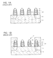
FIGS. 1A to 1E illustrate cross-sectional views of a conventional process of forming a self-aligned contact pad for use in a semiconductor device.
First, as shown in FIG. 1A, a semiconductor substrate 10 includes an active region 11 and a non-active region having a device isolation layer 12. A plurality of gates 20 are formed on corresponding gate oxide layers 21, respectively. Each of the plurality of gates 20 includes a polysilicon layer 22 and a tungsten silicide layer 23 sequentially stacked on the gate oxide layer 21. A nitride layer is formed on a corresponding tungsten silicide layer 23 as a gate mask 30. Thereafter, a nitride spacer 40 is formed on both sidewalls of the gate 20 and the gate mask 30.
As shown in FIG. 1B, an interlayer insulating layer 50 is deposited over the entire surface of the semiconductor substrate 10 and then etched to form an opening 51. In a subsequent process, DC pads and BC pads will be formed on portions of the active region exposed by the opening 51. The interlayer insulating layer 50 is made of a high-density plasma (HDP) oxide layer.
Subsequently, as shown in FIG. 1C, a polysilicon layer 60 is deposited over the entire surface of the semiconductor substrate 10.
Then, as shown in FIG. 1D, the polysilicon layer 60 is etched-back to electrically insulate the contact pads until the HDP oxide interlayer insulating layer 50 is exposed, so that the polysilicon layer 60 remains in the opening 51. Thereafter, the HDP oxide interlayer insulating layer 50 is over-etched by, for example, 500 Å.
As shown in FIG. 1E, the HDP oxide interlayer insulating layer 50 and the polysilicon layer (60 of FIG. 1D) are planarized by a CMP process to electrically insulate the contact pads, thereby forming the contact pads, i.e., DC pads 61 that are bit line self-aligned contact pads and BC pads 62 that are storage node self-aligned contact pads.
However, the conventional method of forming the self-aligned contact pads has the following disadvantages. When the HDP oxide interlayer insulating layer 50 is over-etched, flat zones of a wafer are etched more than other areas due to a uniformity property of dry etching equipment. This excessive over-etching of flat zones of a wafer causes the gate mask 30 of chips on the flat zone of the wafer to be exposed. Since the CMP process is performed in this state, more of the nitride layer 30 (i.e., gate mask) is consumed, and the nitride layer 30 becomes relatively thin. For example, the nitride layer 30 has an average thickness of about 500 Å, but the nitride layer 30 of the chips on the flat zone of the wafer, e.g., a portion of the nitride layer 30, indicated by reference numeral 70 in FIG. 1E, may be over-etched by 250 Å or more. This over-etching may result in a portion of the gate 30 being exposed, thereby causing a defect such as a short circuit between the gate 20 and the contact pads 61 and 62.
To overcome the problems described above, a preferred embodiment of the present invention provides a method of forming a self-aligned contact pad, which may prevent defects such as a short circuit between a gate and a contact pad.
In order to provide the above-mentioned feature, a preferred embodiment of the present invention provides a method of forming a self-aligned contact pad for use in a semiconductor device. The method includes: forming a gate having a gate mask formed thereon on a semiconductor substrate, the semiconductor substrate including an active region and a non-active region, forming a spacer on both sidewalls of the gate and the gate mask, forming an interlayer insulating layer over the entire surface of the semiconductor substrate, the interlayer insulating layer including an opening formed on the active region of the semiconductor substrate, forming a conductive material layer over the entire surface of the semiconductor substrate to cover the interlayer insulating layer, etching-back the conductive material layer until the interlayer insulating layer is exposed, and performing a multi-step CMP process to form contact pads in the opening of the interlayer insulating layer, such that the contact pads are electrically insulated from each other.
Preferably, the multi-step CMP process includes a first CMP process for etching the conductive material layer and the interlayer insulating layer using a first slurry; and a second CMP process for etching the conductive material layer using a second slurry, wherein the second slurry has a higher selectivity in the conductive material layer than in the gate mask to form the contact pads.
The first CMP process is preferably performed using the first slurry until the gate mask is exposed. The first slurry is preferably an oxide slurry such that an etching selectivity ratio of the gate mask, the conductive material layer and the interlayer insulating layer is 1:2:2. The gate mask is preferably a nitride layer, the conductive material layer is preferably a polysilicon layer, and the interlayer insulating layer is preferably a high density plasma (HDP) oxide layer.
In the second CMP process, a width of the gate mask exposed between the contact pads is preferably at least 30 nm, and a thickness of the gate mask is preferably at least 300 Å. The second slurry is preferably a poly slurry such that an etching selectivity ratio of the gate mask and the polysilicon layer is 1:50. The gate mask is preferably a nitride layer, the conductive material layer is preferably a polysilicon layer, and the interlayer insulating layer is preferably a HDP oxide layer. After etching-back the conductive material layer until the interlayer insulating layer is exposed, the method may further include over-etching the interlayer insulating layer. The gate may include a gate oxide layer, a polysilicon layer and a tungsten silicide layer sequentially stacked on the semiconductor substrate.
In a method of the present invention, the self-aligned contact pads are formed using a multi-step CMP process, i.e., a two-step CMP process, and therefore excessive consumption of the nitride layer may be prevented, thereby preventing a defect such as a short circuit between the gate and the contact pads.
For a more complete understanding of the present invention and the features and advantages thereof, reference is now made to the following descriptions taken in conjunction with the accompanying drawings, in which like reference numerals represent like elements throughout, and in which:
FIGS. 1A to 1E illustrate cross-sectional views of a conventional process of forming a self-aligned contact pad for use in a semiconductor device;
FIGS. 2A to 2F illustrate cross-sectional views of a process of forming a self-aligned contact pad according to a preferred embodiment of the present invention;
FIG. 3A is a graph illustrating a thickness of a nitride layer with respect to an oxide layer after a CMP process according to the prior art;
FIG. 3B is a graph illustrating a thickness of a nitride layer with respect to an oxide layer after a CMP process according to a preferred embodiment of the present invention; and
FIG. 4 is a graph illustrating a thickness distribution of the nitride layer when the self-aligned contact pads are formed according to the prior art and according to a preferred embodiment of the present invention.
Korean Patent Application No. 2001-22101, filed Apr. 24, 2001, and entitled “Method of Forming a Self-Aligned Contact Pad for Use in a Semiconductor Device,” is incorporated by reference herein in its entirety.
The present invention will now be described more fully with reference to the accompanying drawings, in which preferred embodiments of the present invention are shown. The present invention may, however, be modified in different forms and should not be construed as limited to the embodiments set forth herein. Rather, these embodiments are provided so that this disclosure will be thorough and complete, and will fully convey the scope of the present invention to those of ordinary skill in the art.
FIGS. 2A to 2F illustrate cross-sectional views of a process of forming a self-aligned contact pad according to a preferred embodiment of the present invention.
First, as shown in FIG. 2A, a semiconductor substrate 100 includes an active region 101 and a non-active region having a device isolation layer 102. A plurality of gates 120 are formed on corresponding gate oxide layers 121, respectively. Each of the plurality of gates 120 includes a polysilicon layer 122 and a tungsten silicide layer 123 which are sequentially stacked on the gate oxide layer 121. A nitride layer 130 is formed on the corresponding tungsten silicide layer 123 as a gate mask. A nitride spacer 140 is formed on both sidewalls of the gate 120 and the nitride layer 130.
More specifically, the gate oxide layer 121, the polysilicon layer 122, the tungsten silicide layer 123, and the nitride layer 130 are sequentially deposited on the semiconductor substrate 100. The nitride layer 130 is patterned using a photoresist pattern (not shown) into a gate mask. Using the patterned nitride layer 130 as the gate mask, the gate oxide layer 121, the polysilicon layer 122 and the tungsten silicide layer 123 are simultaneously etched to form the gate 120. Thereafter, the nitride spacer 140 is formed on both sidewalls of the gate 120 and the nitride layer 130 in a typical manner.
Meanwhile, although not shown in FIG. 2A, after forming the gate 120, a high-density impurity having a predetermined conductivity may be ion-implanted to form source and drain regions. Otherwise, a low-density impurity having a predetermined conductivity is ion-implanted before forming the nitride spacer 140. Thereafter, a high-density impurity having the same conductivity as the low-density impurity is ion-implanted to form source and drain regions having a lightly doped drain (LDD) structure.
Subsequently, as shown in FIG. 2B, an interlayer insulating layer 150 is deposited over the entire surface of the semiconductor substrate 100 and then etched to form an opening 151. In a subsequent process, DC pads and BC pads will be formed on portions of the active region exposed by the opening 151. The interlayer insulating layer 150 is preferably made of a high-density plasma (HDP) oxide layer and preferably, has a thickness of approximately 5300 Å.
Thereafter, as shown in FIG. 2C, a conductive material layer, e.g., polysilicon layer 160, is deposited over the entire surface of the semiconductor substrate 100.
Then, as shown in FIG. 2D, the polysilicon layer 160 is etched-back to electrically insulate the contact pads until the HDP oxide interlayer insulating layer 150 is exposed, so that the polysilicon layer 160 remains in the opening 151. Thereafter, the HDP oxide interlayer insulating layer 150 is over-etched by as much as 500 Å.
As shown in FIG. 2E, the HDP oxide interlayer insulating layer 150 and the polysilicon layer 160 undergo a first CMP process until the nitride layer 130 is exposed. An oxide slurry is used in the first CMP process so that an etching selectivity ratio of the nitride layer, the oxide layer and the polysilicon layer is 1:2:2.
Finally, as shown in FIG. 2F, the HDP oxide interlayer insulating layer 150 and the polysilicon layer (160 of FIG. 2E) undergo a second CMP process to form contact pads 161, 162. A poly slurry is used in the second CMP process so that the polysilicon layer 160 is higher in etching selectivity than the nitride layer 130. The poly slurry etching selectivity ratio of the nitride layer to the polysilicon layer is 1:50. At this time, it is preferred that a thickness d1 from an upper surface of the contact pads 161 and 162 to the tungsten silicide layer 123 is more than 300 Å, and a width d2 of an exposed portion of the nitride layer 130 is more than 30 nm.
Thus, contact pads, i.e., DC pads 161, which are bit line self-aligned contact pads and BC pads 162, which are storage node self-aligned contact pads, are formed.
As a result, the nitride layer 130 and the nitride spacer 140 are sufficiently thick to provide excellent insulation, as indicated by reference numeral 170 in FIG. 2F, thereby preventing defects such as a short circuit between the gate 120 and the contact pads 161 and 162.
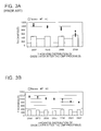
FIG. 3A is a graph illustrating a thickness of the nitride layer with respect to the oxide layer after the CMP process according to the prior art. FIG. 3B is a graph illustrating a thickness of the nitride layer with respect to the oxide layer after the CMP process according to a preferred embodiment of the present invention. In FIGS. 3A and 3B, “□” denotes a recess degree of the polysilicon layer for the contact pads, “E” denotes an edge portion of a chip on a wafer, and “C” denotes a central portion of the chip on the wafer. In the graphs of FIGS. 3A and 3B, a vertical axis denotes a thickness of the nitride layer, and a horizontal axis denotes a thickness of the HDP oxide layer after the CMP process.
As shown in FIG. 3A, a recess degree of the polysilicon layer is about 500 Å. In this case, the HDP oxide layer must have a minimum thickness of 800 Å in order to prevent a short circuit between the gate and the contact pads. However, when the oxide layer that is formed in the chip on the flat zone of the wafer has a thickness of 2359 Å, the nitride layer formed on an edge portion of the chip is below 500 Å, leading to a defect such as a short circuit between the gate and the contact pads.
On the other hand, as shown in FIG. 3B, a recess degree of the polysilicon layer is about 300 Å. In this case, the HDP oxide layer must have a minimum thickness of 600 Å to prevent a short circuit between the gate and the contact pads. The nitride layer formed in all of the chips on the wafer has a thickness of greater than 500 Å, thereby preventing generation of a defect such as a short circuit between the gate and the contact pads.
FIG. 4 is a graph illustrating a thickness distribution of the nitride layer when the self-aligned contact pads are formed according to a method of the prior art and according to a preferred embodiment of the present invention. In the graph of FIG. 4, section “A” denotes a thickness distribution of the nitride layer when the self-aligned contact pads are formed according to the prior art, and section “B” denotes a thickness distribution of the nitride layer when the self-aligned contact pads are formed according to a preferred embodiment of the present invention.
As shown in FIG. 4, in the case of the prior art “A”, most of the nitride layers have a thickness of less than 500 Å, and many nitride layers have a thickness of less than 300 Å, wherein 300 Å is the minimum allowable thickness of the nitride layer. However, in the case of the present invention “B”, most of the nitride layers have a thickness of greater than 500 Å, and few nitride layers have a thickness less than 300 Å, wherein 300 Å is the minimum allowable thickness of the nitride layer.
As described herein, the self-aligned contact pads are formed according to the present invention using a multi-step CMP process, i.e., a two-step CMP process, and therefore excessive consumption of the nitride layer may be prevented, thereby preventing a defect such as a short circuit between the gate and the contact pads.
A preferred embodiment of the present invention has been disclosed herein and, although specific terms are employed, they are used in a generic and descriptive sense only and not for purpose of limitation. Accordingly, it will be understood by those of ordinary skill in the art that various changes in form and details may be made without departing from the spirit and scope of the invention as set forth in the following claims.
Claims (9)
1. A method of forming a self-aligned contact pad for use in a semiconductor device, comprising:
forming a gate having a gate mask formed thereon on a semiconductor substrate, the semiconductor substrate including an active region and a non-active region;
forming a spacer on both sidewalls of the gate and the gate mask;
forming an interlayer insulating layer over the entire surface of the semiconductor substrate, the interlayer insulating layer including an opening formed on the active region of the semiconductor substrate;
forming a conductive material layer over the entire surface of the semiconductor substrate to cover the interlayer insulating layer;
etching-back the conductive material layer until the interlayer insulating layer is exposed; and
performing a multi-step chemical mechanical polishing (CMP) process including a first CMP process for etching the conductive material layer and the interlayer insulating layer using a first slurry;
and a second CMP process for etching the conductive material layer using a second slurry, wherein the second slurry has a higher selectivity in the conductive material layer than in the gate mask, to form contact pads in the opening of the interlayer insulating layer, such that the contact pads are electrically insulated from each other.
2. The method as claimed in claim 1 , wherein the gate includes a gate oxide layer, a polysilicon layer and a tungsten silicide layer sequentially stacked on the semiconductor substrate.
3. The method as claimed in claim 1 , wherein the first CMP process is performed using the first slurry until the gate mask is exposed.
4. The method as claimed in claim 3 , wherein the first slurry is an oxide slurry such that an etching selectivity ratio of the gate mask, the conductive material layer and the interlayer insulating layer is 1:2:2.
5. The method as claimed in claim 4 , wherein the gate mask is a nitride layer, the conductive material layer is a polysilicon layer, and the interlayer insulating layer is a high-density plasma (HDP) oxide layer.
6. The method as claimed in claim 1 , wherein in the second CMP process, a width of the gate mask exposed between the contact pads is at least 30 nm, and a thickness of the gate mask is at least 300 Å.
7. The method as claimed in claim 6 , wherein the second slurry is a poly slurry such that an etching selectivity ratio of the gate mask and the polysilicon layer is 1:50.
8. The method as claimed in claim 7 , wherein the gate mask is a nitride layer, the conductive material layer is a polysilicon layer, and the interlayer insulating layer is a HDP oxide layer.
9. A method of forming a self-aligned contact pad for use in a semiconductor device, comprising:
forming a gate having a gate mask formed thereon on a semiconductor substrate, the semiconductor substrate including an active region and a non-active region;
forming a spacer on both sidewalls of the gate and the gate mask;
forming an interlayer insulating layer over the entire surface of the semiconductor substrate, the interlayer insulating layer including an opening formed on the active region of the semiconductor substrate;
forming a conductive material layer over the entire surface of the semiconductor substrate to cover the interlayer insulating layer;
etching-back the conductive material layer until the interlayer insulating layer is exposed and then over-etching the interlayer insulating layer; and
performing a multi-step chemical mechanical polishing (CMP) process to form contact pads in the opening of the interlayer insulating layer, such that the contact pads are electrically insulated from each other.
Applications Claiming Priority (2)
| Application Number | Priority Date | Filing Date | Title |
|---|---|---|---|
| KR2001-22101 | 2001-04-24 | ||
| KR10-2001-0022101A KR100410980B1 (en) | 2001-04-24 | 2001-04-24 | Method for Forming SAC Contact pad in Semiconductor Device |
Publications (2)
| Publication Number | Publication Date |
|---|---|
| US20020155687A1 US20020155687A1 (en) | 2002-10-24 |
| US6706633B2 true US6706633B2 (en) | 2004-03-16 |
Family
ID=19708639
Family Applications (1)
| Application Number | Title | Priority Date | Filing Date |
|---|---|---|---|
| US10/115,430 Expired - Lifetime US6706633B2 (en) | 2001-04-24 | 2002-04-04 | Method of forming a self-aligned contact pad for use in a semiconductor device |
Country Status (3)
| Country | Link |
|---|---|
| US (1) | US6706633B2 (en) |
| JP (1) | JP4303444B2 (en) |
| KR (1) | KR100410980B1 (en) |
Cited By (1)
| Publication number | Priority date | Publication date | Assignee | Title |
|---|---|---|---|---|
| US20080009136A1 (en) * | 2004-07-15 | 2008-01-10 | Samsung Electronics Co., Ltd., | Polishing Method |
Families Citing this family (5)
| Publication number | Priority date | Publication date | Assignee | Title |
|---|---|---|---|---|
| US6632235B2 (en) | 2001-04-19 | 2003-10-14 | Synthes (U.S.A.) | Inflatable device and method for reducing fractures in bone and in treating the spine |
| KR100414731B1 (en) * | 2001-06-30 | 2004-01-13 | 주식회사 하이닉스반도체 | A method for forming a contact plug of a semiconductor device |
| KR100442962B1 (en) * | 2001-12-26 | 2004-08-04 | 주식회사 하이닉스반도체 | Method for manufacturing of metal line contact plug of semiconductor device |
| KR100444302B1 (en) * | 2001-12-29 | 2004-08-11 | 주식회사 하이닉스반도체 | Manufacturing method of semiconductor device |
| KR100487917B1 (en) * | 2002-05-20 | 2005-05-06 | 주식회사 하이닉스반도체 | Chemical mechanical polishing method of semiconductor device |
Citations (3)
| Publication number | Priority date | Publication date | Assignee | Title |
|---|---|---|---|---|
| US5707883A (en) * | 1992-10-23 | 1998-01-13 | Yamaha Corporation | Method for manufacturing a semiconductor device using antireflection coating |
| US6337275B1 (en) * | 1998-06-17 | 2002-01-08 | Samsung Electronics Co., Ltd. | Method for forming a self aligned contact in a semiconductor device |
| US6455381B1 (en) * | 1999-05-27 | 2002-09-24 | Mitsubishi Denki Kabushiki Kaisha | Method of manufacturing a semiconductor device having a trench isolation structure |
Family Cites Families (4)
| Publication number | Priority date | Publication date | Assignee | Title |
|---|---|---|---|---|
| KR100281692B1 (en) * | 1998-10-17 | 2001-03-02 | 윤종용 | Self-aligned contact pad of semiconductor device and method of forming the same |
| KR100546152B1 (en) * | 1998-12-28 | 2006-04-14 | 주식회사 하이닉스반도체 | Contact Forming Method of Semiconductor Device |
| KR100546153B1 (en) * | 1998-12-28 | 2006-03-31 | 주식회사 하이닉스반도체 | Contact Forming Method of Semiconductor Device |
| KR20000060603A (en) * | 1999-03-17 | 2000-10-16 | 윤종용 | Method for forming high integration self-aligned contact pad |
-
2001
- 2001-04-24 KR KR10-2001-0022101A patent/KR100410980B1/en active IP Right Grant
-
2002
- 2002-04-04 US US10/115,430 patent/US6706633B2/en not_active Expired - Lifetime
- 2002-04-24 JP JP2002122102A patent/JP4303444B2/en not_active Expired - Fee Related
Patent Citations (3)
| Publication number | Priority date | Publication date | Assignee | Title |
|---|---|---|---|---|
| US5707883A (en) * | 1992-10-23 | 1998-01-13 | Yamaha Corporation | Method for manufacturing a semiconductor device using antireflection coating |
| US6337275B1 (en) * | 1998-06-17 | 2002-01-08 | Samsung Electronics Co., Ltd. | Method for forming a self aligned contact in a semiconductor device |
| US6455381B1 (en) * | 1999-05-27 | 2002-09-24 | Mitsubishi Denki Kabushiki Kaisha | Method of manufacturing a semiconductor device having a trench isolation structure |
Cited By (3)
| Publication number | Priority date | Publication date | Assignee | Title |
|---|---|---|---|---|
| US20080009136A1 (en) * | 2004-07-15 | 2008-01-10 | Samsung Electronics Co., Ltd., | Polishing Method |
| US20080042100A1 (en) * | 2004-07-15 | 2008-02-21 | Samsung Electronics Co., Ltd. | Slurry composition |
| US8048809B2 (en) | 2004-07-15 | 2011-11-01 | Samsung Electronics Co., Ltd. | Polishing method using chemical mechanical slurry composition |
Also Published As
| Publication number | Publication date |
|---|---|
| US20020155687A1 (en) | 2002-10-24 |
| JP4303444B2 (en) | 2009-07-29 |
| JP2003023077A (en) | 2003-01-24 |
| KR20020082960A (en) | 2002-11-01 |
| KR100410980B1 (en) | 2003-12-18 |
Similar Documents
| Publication | Publication Date | Title |
|---|---|---|
| KR100740952B1 (en) | Method for forming a semiconductor device | |
| US6784501B2 (en) | Process for forming metalized contacts to periphery transistors | |
| US20020024093A1 (en) | Semiconductor device with self-aligned contact structure employing dual spacers and method of manufacturing the same | |
| US6607955B2 (en) | Method of forming self-aligned contacts in a semiconductor device | |
| KR100284535B1 (en) | Self-aligned contact formation method of semiconductor device | |
| US6255224B1 (en) | Method of forming contact for semiconductor device | |
| US20020042196A1 (en) | Method of manufacturing a semiconductor device using anti-reflective layer and self-aligned contact technique and semiconductor device manufactured thereby | |
| US6197670B1 (en) | Method for forming self-aligned contact | |
| US6649503B2 (en) | Methods of fabricating integrated circuit devices having spin on glass (SOG) insulating layers and integrated circuit devices fabricated thereby | |
| KR20050000798A (en) | Semiconductor device and Method for manufacturing the same | |
| US6953744B2 (en) | Methods of fabricating integrated circuit devices providing improved short prevention | |
| US6706633B2 (en) | Method of forming a self-aligned contact pad for use in a semiconductor device | |
| US6200849B1 (en) | Methods of fabricating conductive contacts for integrated circuit memory devices using first and second dielectric layers and first and second conductive layers | |
| KR100252039B1 (en) | Method for forming a self-aligned contact hole | |
| US6559044B1 (en) | Method for forming contacts | |
| KR20010036018A (en) | Bit line contact of a semiconductor device and method of forming the same | |
| KR100200740B1 (en) | Manufacturing method of semiconductor device in contact structure | |
| KR0158905B1 (en) | Manufacture of semiconductor memory device | |
| KR20010028057A (en) | Bit line contact with a stable contact resistance and method of forming the same | |
| KR20050066164A (en) | Semiconductor device and method of manufacturing semiconductor device | |
| KR20010063460A (en) | Method of forming a gate electrode in a semiconductor device | |
| KR20020075067A (en) | Method for forming a contact and bit line of flash memory device | |
| KR20010036748A (en) | Method for fabricating a dram in a smeiconductor device with minimized underlayer consumption | |
| KR20040009390A (en) | Method of forming contact of semiconductor device | |
| KR20060002149A (en) | Method for forming interlayer dielectric film |
Legal Events
| Date | Code | Title | Description |
|---|---|---|---|
| AS | Assignment |
Owner name: SAMSUNG ELECTRONICS CO., LTD., KOREA, REPUBLIC OF Free format text: ASSIGNMENT OF ASSIGNORS INTEREST;ASSIGNORS:CHUNG, DAE-HYUK;LEE, HAN-JOO;HWANG, IN-SEAK;REEL/FRAME:012778/0536;SIGNING DATES FROM 20020322 TO 20020326 |
|
| FEPP | Fee payment procedure |
Free format text: PAYOR NUMBER ASSIGNED (ORIGINAL EVENT CODE: ASPN); ENTITY STATUS OF PATENT OWNER: LARGE ENTITY |
|
| STCF | Information on status: patent grant |
Free format text: PATENTED CASE |
|
| FPAY | Fee payment |
Year of fee payment: 4 |
|
| FPAY | Fee payment |
Year of fee payment: 8 |
|
| FPAY | Fee payment |
Year of fee payment: 12 |