US6683267B1 - Gas-insulated switchgear device - Google Patents
Gas-insulated switchgear device Download PDFInfo
- Publication number
- US6683267B1 US6683267B1 US10/088,482 US8848202A US6683267B1 US 6683267 B1 US6683267 B1 US 6683267B1 US 8848202 A US8848202 A US 8848202A US 6683267 B1 US6683267 B1 US 6683267B1
- Authority
- US
- United States
- Prior art keywords
- terminal
- moving contact
- switchgear device
- switchgear
- interruption
- Prior art date
- Legal status (The legal status is an assumption and is not a legal conclusion. Google has not performed a legal analysis and makes no representation as to the accuracy of the status listed.)
- Expired - Lifetime
Links
Images


Classifications
-
- H—ELECTRICITY
- H02—GENERATION; CONVERSION OR DISTRIBUTION OF ELECTRIC POWER
- H02B—BOARDS, SUBSTATIONS OR SWITCHING ARRANGEMENTS FOR THE SUPPLY OR DISTRIBUTION OF ELECTRIC POWER
- H02B13/00—Arrangement of switchgear in which switches are enclosed in, or structurally associated with, a casing, e.g. cubicle
- H02B13/02—Arrangement of switchgear in which switches are enclosed in, or structurally associated with, a casing, e.g. cubicle with metal casing
- H02B13/035—Gas-insulated switchgear
Definitions
- the present invention relates to a gas-insulated switchgear device for high- and medium-voltage applications, having improved functions and characteristics; the expression “high- and medium-voltage applications” is used to reference applications with operating voltages equal to or above 1000 Volt.
- the device according to the invention by virtue of its innovative structure, allows to optimize execution of the required electric maneuvers, according to a solution which is at once simple, effective and compact.
- the contacts are moved by using actuation devices which generally comprise actuators of the mechanical or hydraulic type which require complicated kinematic systems to transmit motion to the moving contact.
- the disconnection maneuver requires the coordinated movement of one or more moving contacts, so that the opening/closure of the disconnection contacts occurs in the intended sequence.
- This usually entails complicated coupling mechanisms and/or complicated actuation and control systems, especially when disconnection occurs on multiple-bar systems.
- maintenance interventions are necessary in order to maintain nominal behavior and ensure repeatability of performance.
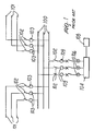
- FIG. 1 schematically illustrates a minimal configuration of an electrical substation of the single distribution bar type.
- each phase of the main power line 101 is connected in input to a corresponding distribution bar 100 ; at least one disconnector 102 and a current transformer 103 are used along the junction conductor that connects a phase of the line 101 to the corresponding bar 100 .
- each bar 100 is electrically connected to a power transformer 104 , which appropriately varies the voltage so as to obtain an adequate level thereof in input to a set of medium-voltage devices, generally designated by the reference numeral 105 ; ahead of the power transformer 104 there are also surge arresters 106 which protect the transformer against possible damage.
- a second disconnector 102 , a second current transformer 103 and a circuit breaker 109 are used along the connection between each bar 100 and the power transformer 104 .
- each bar 100 is connected to the corresponding phase of the line 101 according to an architecture which is similar to the input architecture, i.e., by using another disconnector 102 and an additional current transformer 103 .
- the minimum configuration of the electrical substation is generally conveniently supplemented by using additional primary components; in particular, two voltage transformers, two disconnectors and two circuit breakers are used for each phase of the main power line 101 , arranging them respectively at the input connection and in output between the line phase and the bar of the substation.
- the substation is furthermore equipped with a series of secondary components, constituted by protection and control systems, in order to ensure the correct electrical operation of the system and avoid dangerous damage.
- substations Owing to the large number of components required, even for the provision of a minimal configuration, known types of substation are unsatisfactory in practical use mainly due to their high cost, to their space occupation requirements and to the need for frequent maintenance. Said substations furthermore do not have a structure of the modular type which makes them conveniently flexible in their applications and easy to implement according to the various application requirements.
- the aim of the present invention is to provide a gas-insulated switchgear device for high- and medium-voltage applications which is capable of integrating the functions that in the current art are performed by multiple structurally mutually distinct components.
- an object of the present invention is to provide a gas-insulated switchgear device for high- and medium-voltage applications which allows great flexibility and simplicity in the execution of the required electric switching operations.
- Another object of the present invention is to provide a gas-insulated switchgear device for high- and medium-voltage applications which has a compact structure and small dimensions, so as to significantly reduce the space occupation requirements.
- Another object of the present invention is to provide a gas-insulated switchgear device for high- and medium-voltage applications which has a reduced mechanical complexity.
- Another object of the present invention is to provide a gas-insulated switchgear device for high- and medium-voltage applications which easily allows to realize different application configurations, particularly for the implementation of substations with a single and/or double conducting bar system.
- Another object of the present invention is to provide a gas-insulated switchgear device for high- and medium-voltage applications which is highly reliable, relatively easy to manufacture and at competitive costs.
- a gas-insulated switchgear device for high- and medium-voltage applications, characterized in that it comprises an enclosure which contains a disconnection unit which is electrically connected to a first electric terminal and is arranged in the enclosure in a substantially central position, and a first interruption unit and a second interruption unit which are connected electrically to the disconnection unit and, respectively, to a second electric terminal and a third electric terminal, said first and second interruption units being arranged mutually opposite with respect to the disconnection unit.
- the device according to the invention can be of the segregated-phase or joined-phase type, for a single-bar or multiple-bar system, with single-pole or three-pole actuation.
- the device according to the invention therefore has a compact structure which integrates, within a single body, both the circuit-breaking elements and the disconnection elements, according to a solution which in any case allows to perform the required electrical switching operations simply and effectively.
- FIG. 1 is a schematic view of a known type of electric power transmission and distribution substation
- FIG. 2 is a view of the switchgear device according to the invention.
- FIGS. 3 a - 3 f are schematic views of some possible electrical switching operations that can be performed with the device of FIG. 2;
- FIGS. 4 and 5 are views of a possible embodiment of an electric substation with a three-phase single-bar system which uses the device of FIG. 2 .
- the switchgear device generally designated by the reference numeral 200 , comprises an enclosure 1 which contains an insulating gas and internally accommodates a first interruption unit 4 , a second interruption unit 14 and a disconnection unit 5 .
- the disconnection unit 5 is electrically connected to a first electric terminal 2 and to the two interruption units 4 and 14 in the manner described hereinafter; in turn, the interruption units 4 and 14 are electrically connected to a second electric terminal 11 and to a third electric terminal 13 , respectively.
- the electric terminals 2 , 11 and 13 (which are partially visible in the figure) are accommodated in corresponding bushings, designated by the reference numerals 40 , 41 and 42 respectively, which are connected to the enclosure 1 .
- the disconnection unit 5 is arranged inside the enclosure 1 in a substantially central position, with the two interruption units 4 and 14 arranged mutually opposite with respect to the disconnection unit 5 .
- the interruption units 4 and 14 comprise an interruption chamber 3 which accommodates a fixed contact 6 and a moving contact 7 which is operatively controlled by actuation means; the moving contact 7 of each one of the interruption units 4 and 14 is electrically connected to the terminal 11 and to the terminal 13 , respectively.
- the actuation means comprise an actuating rod 8 which is connected to the moving contact 7 and is actuated by an appropriate actuation and control device 10 .
- the actuation and control device can be constituted by a mechanical or hydraulic or hydraulic-pneumatic or electric actuator; preferably, the use of an electric motor with position control, particularly a servomotor, allows advantages in terms of speed and precision in executing the contact opening/closure switching operations.
- the disconnection unit 5 comprises a first fixed contact 21 which is connected to the electric terminal 2 , a second fixed contact 22 which is connected to the fixed contact 7 of the interruption unit 4 , a third fixed contact 23 which is connected to the fixed contact 7 of the interruption unit 14 , and at least one moving contact 24 which can be coupled to at least one of the fixed contacts 21 , 22 and 23 .
- the disconnection unit 5 comprises a single moving contact 24 which can be coupled to the three fixed contacts 21 , 22 and 23 ; said moving contact 24 , which is constituted for example by a blade which has a sector-like profile, is fixed to a rotating shaft 12 substantially at right angles to the axis of the shaft 12 .
- the moving contact 24 rotates rigidly with the shaft 12 and the fixed contacts 21 , 22 and 23 lie on its plane of rotation.
- reference is always meant to the relative position of the ends of the fixed contact and of the moving contact that can be coupled thereto.
- the fixed contacts 21 , 22 and 23 are on multiple mutually offset planes, using in this case multiple moving contacts which are fixed to the rotating shaft 12 ; in this case, the moving contacts rotate on different planes and are arranged at an appropriate angle to each other so as to allow electrical connections between the pairs of contacts in the intended sequences.
- the rotating shaft 12 is actuated by appropriate actuation means, preferably constituted by an electric motor, not shown, which is operatively connected to said shaft 12 .
- actuation means preferably constituted by an electric motor, not shown, which is operatively connected to said shaft 12 .
- actuation means preferably constituted by an electric motor, not shown, which is operatively connected to said shaft 12 .
- a servomotor provides considerable advantages in terms of operation precision and speed.
- mechanical or hydraulic actuation means can also be provided as an alternative, or as an addition, to the above described actuation means, particularly for performing emergency manual operations.
- the disconnection unit 5 furthermore comprises a fourth fixed contact 25 which is grounded.
- the fixed contact 25 is connected to the enclosure 1 , which is grounded, and lies on a plane which is different from the plane of the fixed contacts 21 , 22 and 23 .
- the device according to the invention uses a second moving contact 26 which can be coupled to the fixed contact 25 ; said moving contact 26 , which is for example configured like an L-shaped blade with substantially identical sides, is fixed to the shaft 12 and rotates rigidly therewith on the plane of rotation on which said fixed contact 25 lies.
- the solution shown in FIG. 2 is particularly advantageous, in that the longitudinal axes of the two interruption chambers 4 and 14 are substantially mutually aligned and lie at right angles to the rotation axis of the switching shaft 12 ; in this manner, the maneuvers of the disconnection unit occurs by turning the shaft 12 and by turning the moving contacts about the axis of said shaft, while the opening/closure of the interruption units 4 and 14 occurs by virtue of a simple translatory motion of the moving contacts along the longitudinal axis of the respective interruption chamber.
- the disconnection unit 5 can be arranged so that the axis of the rotation shaft 12 is positioned in a substantially horizontal plane, as shown in FIG. 2, or alternatively, so that the axis of the rotation shaft 12 is positioned in a substantially vertical plane, i.e. in a direction which is perpendicular to the axis position of FIG. 2 and to the longitudinal axes of the interruption units; in this case, the motor which drives the shaft 12 may be positioned on the lower part of the enclosure 1 , with the disconnection contacts correspondigly arranged inside the enclosure itself.
- the device thus conceived, by virtue of its structural compactness and functional flexibility, is particularly suitable for use in a substation for electric power transmission and distribution, both with a three-phase system with single conducting bar and with a three-phase system with two conducting bars, according to several application configurations. Accordingly, the present invention also relates to a substation for electric power transmission and distribution which is connected to a three-phase power supply line and is characterized in that it comprises at least one switchgear device according to the invention.
- a load for example a power transformer
- Another possible alternative is to connect the terminal 2 in input to the power supply phase and the terminals 11 and 13 to two corresponding loads, for example two power transformers.
- FIGS. 4 and 5 A preferred embodiment of a substation with a three-phase single-bar system, using multiple switchgear devices 200 according to the invention, is shown in FIGS. 4 and 5.
- each phase 30 of a three-phase power supply line to which the substation is connected uses two switchgear devices 200 .
- a first device 200 has a terminal 11 connected in input to the power supply phase 30 , a terminal 13 connected in output to a power transformer 31 , and a terminal 2 connected, by means of an air-insulated conducting bar 50 , to the corresponding terminal 2 of the second device 200 .
- the second device 200 has its terminals 11 and 13 (or, vice versa, 13 and 11 ) connected respectively in output to the power supply phase 30 and to a power transformer 31 .
- the devices used in the substation can be of the single-pole actuation type, in which actuation means are provided on each individual phase to perform the disconnecting operation; as an alternative, they can be of the type with three-pole actuation, in which the energy for performing disconnection on the three phases of the device is provided by a single actuation means which is mechanically coupled to the disconnection units of each individual phase.
- actuation means are provided on each individual phase to perform the disconnecting operation
- they can be of the type with three-pole actuation, in which the energy for performing disconnection on the three phases of the device is provided by a single actuation means which is mechanically coupled to the disconnection units of each individual phase.
- FIGS. 4 and 5 An example in this regard is shown schematically in FIGS. 4 and 5, in which each one of the two sets of three devices 200 uses a single electric motor 60 , preferably a servomotor. In this case, as shown in FIG.
- the motor 60 is located at one of the devices 200 that are arranged laterally and is connected to the three corresponding disconnection units by means of a single through shaft 61 on which the various moving contacts are appropriately arranged.
- the motor 60 can also be arranged on the central device 200 .
- a similar actuation system with single three-pole actuation can also be used for switching the interruption units; in this case it is in fact sufficient to use two motors 10 , arranged at a device 200 , each of which is mechanically connected to the actuation rods of the moving contacts of three interruption units arranged side by side.
- the substation shown in FIGS. 4 and 5 can furthermore be implemented by using, for example, an additional set of three devices 200 arranged side by side and connected sequentially to the first two sets of three, as described above; the connection between the sets of three can furthermore be provided by using, instead of the bars 30 , junction devices of the type known in the art, provided with interruption units where necessary.
- the connection between pairs of devices 200 can be provided by replacing the containment bushings 40 and the conducting bars 30 with metal-clad ducts, so as to provide an even more compact metal-clad structure, with a reduced vertical extension and accordingly with a reduced visual impact. In this manner it is furthermore possible to eliminate the air-insulated bars, with a consequent advantage from the point of view of maintenance.
- the terminals 11 and 13 can be accommodated in the respective bushings 41 and 42 and can also be connected to the power supply phases directly by cabling instead of by air-insulated means.
- the switchgear device 200 can be modified in a very simple way; in this case it is in fact sufficient to use a fourth connection terminal and to provide the disconnection unit with an additional fixed contact, which is connected to the fourth terminal, and optionally with a further moving contact which can be coupled to said fixed contact.
- the fourth terminal can be accommodated in a bushing which is arranged proximate to the bushing 40 and is connected to the corresponding bushing of the second device 200 with a bar 30 , as described earlier; in this case also, in order to provide the connections between the pairs of devices 200 it is possible to use metal-clad ducts instead of the containment bushings and the conducting bars.
- the electrical connections in input and in output to the devices 200 can furthermore be provided by air-insulated means, by utilizing the bushings, or by providing cabled connections.
- gas-insulated switchgear device thus conceived is susceptible of modifications and variations, all of which are within the scope of the inventive concept; all the details may furthermore be replaced with technically equivalent elements.
- the configurations considered, so long as they are compatible with the specific use, as well as the individual components, may be any according to the requirements and the state of the art.
Landscapes
- Engineering & Computer Science (AREA)
- Power Engineering (AREA)
- Gas-Insulated Switchgears (AREA)
- Driving Mechanisms And Operating Circuits Of Arc-Extinguishing High-Tension Switches (AREA)
- Regulation And Control Of Combustion (AREA)
- Air Bags (AREA)
- Incineration Of Waste (AREA)
- Transformer Cooling (AREA)
Applications Claiming Priority (3)
| Application Number | Priority Date | Filing Date | Title |
|---|---|---|---|
| IT1999MI002060A IT1313321B1 (it) | 1999-10-01 | 1999-10-01 | Apparecchiatura di interruzione e sezionamento isolata in gas. |
| ITMI99A2060 | 1999-10-01 | ||
| PCT/EP2000/009580 WO2001026198A1 (fr) | 1999-10-01 | 2000-09-25 | Appareillage de commutation isole par gaz |
Publications (1)
| Publication Number | Publication Date |
|---|---|
| US6683267B1 true US6683267B1 (en) | 2004-01-27 |
Family
ID=11383712
Family Applications (1)
| Application Number | Title | Priority Date | Filing Date |
|---|---|---|---|
| US10/088,482 Expired - Lifetime US6683267B1 (en) | 1999-10-01 | 2000-09-25 | Gas-insulated switchgear device |
Country Status (8)
| Country | Link |
|---|---|
| US (1) | US6683267B1 (fr) |
| EP (1) | EP1218995B1 (fr) |
| CN (1) | CN1237679C (fr) |
| AT (1) | ATE242924T1 (fr) |
| AU (1) | AU7910700A (fr) |
| DE (1) | DE60003327T2 (fr) |
| IT (1) | IT1313321B1 (fr) |
| WO (1) | WO2001026198A1 (fr) |
Cited By (16)
| Publication number | Priority date | Publication date | Assignee | Title |
|---|---|---|---|---|
| US20040042158A1 (en) * | 2002-08-29 | 2004-03-04 | Mitsubishi Denki Kabushiki Kaisha | Gas-insulated switchgear |
| US20050150869A1 (en) * | 2003-12-02 | 2005-07-14 | Vei Power Distribution S.P.A. | Isolator/circuit-breaker device for electric substations |
| EP1569310A1 (fr) * | 2004-02-27 | 2005-08-31 | ABB Technology AG | Interrupteur blindé monophasé isolé au gas |
| EP1589625A1 (fr) * | 2004-04-19 | 2005-10-26 | ABB Technology AG | Dispositif de commutation isolé par gaz |
| US20050236371A1 (en) * | 2004-04-19 | 2005-10-27 | Abb Technology Ag | Gas-insulated switchgear device |
| US20060049144A1 (en) * | 2004-09-07 | 2006-03-09 | Vei Power Distribution S.P.A. | Switch and disconnector apparatus for electric substations |
| US20080042786A1 (en) * | 2004-06-16 | 2008-02-21 | Siement Atkiengesellschaft | Power Switch Comprising an Interrupter Unit Disposed within an Encapsulating Housing |
| US20080093344A1 (en) * | 2005-07-29 | 2008-04-24 | Siemens Transmission & Distribution Sa | Electrical Switchgear |
| US20080105654A1 (en) * | 2004-12-13 | 2008-05-08 | Siemens Aktiengesellschaft | Polyphase Switching Device Comprising at Least Three Similar Interrupter Units |
| US20110216463A1 (en) * | 2010-03-08 | 2011-09-08 | Kester Jeffrey J | Line protection systems |
| US20120103941A1 (en) * | 2009-10-29 | 2012-05-03 | Mitsubishi Electric Corporation | Power switching apparatus |
| US20120175234A1 (en) * | 2011-01-06 | 2012-07-12 | Hitachi, Ltd. | Switch Unit and Switchgear |
| US20140196932A1 (en) * | 2011-07-05 | 2014-07-17 | Schneider Electric Industries Sas | Use of a mixture comprising a hydrofluoroolefin as a medium-voltage arc-extinguishing and/or insulating gas and medium-voltage electrical device comprising same |
| US20140246298A1 (en) * | 2013-03-01 | 2014-09-04 | Abb Technology Ag | High voltage switching device |
| US9893515B2 (en) * | 2012-09-26 | 2018-02-13 | Mitsubishi Electric Corporation | Power switchgear having surge suppression apparatus |
| US20220231488A1 (en) * | 2019-05-31 | 2022-07-21 | Hitachi Energy Switzerland Ag | Tower mounted high voltage switchgear |
Families Citing this family (5)
| Publication number | Priority date | Publication date | Assignee | Title |
|---|---|---|---|---|
| DE102004006062A1 (de) * | 2004-01-30 | 2005-08-18 | Siemens Ag | Druckgasisoliertes Schaltgerät |
| KR100846223B1 (ko) * | 2006-03-09 | 2008-07-15 | (주)서전기전 | 중전압 스위치기어 |
| DE102007004950B4 (de) | 2006-03-09 | 2008-07-17 | Switchcraft Europe Gmbh | Elektrische Schaltanlage |
| CN103368080B (zh) * | 2013-07-17 | 2015-08-05 | 牛虎明 | 气体绝缘的高压组合电器 |
| CN105742968A (zh) * | 2014-12-11 | 2016-07-06 | 中电新源智能电网科技有限公司 | 一种高、中压电气设备的连接方式 |
Citations (5)
| Publication number | Priority date | Publication date | Assignee | Title |
|---|---|---|---|---|
| US4291363A (en) * | 1979-05-31 | 1981-09-22 | Hitachi, Ltd. | Gas-insulated switchgear apparatus |
| US4300028A (en) * | 1979-09-25 | 1981-11-10 | Gould Inc. | Rotary switch for gas-insulated substations |
| US4379957A (en) * | 1981-01-14 | 1983-04-12 | Westinghouse Electric Corp. | Modular "Y"-type enclosure elements for gas insulated substations |
| GB2143089A (en) | 1983-06-10 | 1985-01-30 | Mitsubishi Electric Corp | Switchgear |
| US5796060A (en) * | 1995-03-28 | 1998-08-18 | Asea Brown Boveri Ag | Gas insulated switchgear with grounding and disconnecting switches |
-
1999
- 1999-10-01 IT IT1999MI002060A patent/IT1313321B1/it active
-
2000
- 2000-09-25 AT AT00969356T patent/ATE242924T1/de not_active IP Right Cessation
- 2000-09-25 EP EP00969356A patent/EP1218995B1/fr not_active Expired - Lifetime
- 2000-09-25 WO PCT/EP2000/009580 patent/WO2001026198A1/fr active IP Right Grant
- 2000-09-25 AU AU79107/00A patent/AU7910700A/en not_active Abandoned
- 2000-09-25 US US10/088,482 patent/US6683267B1/en not_active Expired - Lifetime
- 2000-09-25 DE DE60003327T patent/DE60003327T2/de not_active Expired - Lifetime
- 2000-09-25 CN CNB008137552A patent/CN1237679C/zh not_active Expired - Lifetime
Patent Citations (5)
| Publication number | Priority date | Publication date | Assignee | Title |
|---|---|---|---|---|
| US4291363A (en) * | 1979-05-31 | 1981-09-22 | Hitachi, Ltd. | Gas-insulated switchgear apparatus |
| US4300028A (en) * | 1979-09-25 | 1981-11-10 | Gould Inc. | Rotary switch for gas-insulated substations |
| US4379957A (en) * | 1981-01-14 | 1983-04-12 | Westinghouse Electric Corp. | Modular "Y"-type enclosure elements for gas insulated substations |
| GB2143089A (en) | 1983-06-10 | 1985-01-30 | Mitsubishi Electric Corp | Switchgear |
| US5796060A (en) * | 1995-03-28 | 1998-08-18 | Asea Brown Boveri Ag | Gas insulated switchgear with grounding and disconnecting switches |
Cited By (31)
| Publication number | Priority date | Publication date | Assignee | Title |
|---|---|---|---|---|
| US6946613B2 (en) * | 2002-08-29 | 2005-09-20 | Mitsubishi Denki Kabushiki Kaisha | Gas-insulated switchgear |
| US20040042158A1 (en) * | 2002-08-29 | 2004-03-04 | Mitsubishi Denki Kabushiki Kaisha | Gas-insulated switchgear |
| US20050150869A1 (en) * | 2003-12-02 | 2005-07-14 | Vei Power Distribution S.P.A. | Isolator/circuit-breaker device for electric substations |
| US7091439B2 (en) * | 2003-12-02 | 2006-08-15 | Vei Power Distribution, S.P.A. | Isolator/circuit-breaker device for electric substations |
| US20060283841A1 (en) * | 2004-02-27 | 2006-12-21 | Abb Technology Ag | Encapsulated gas-insulated switchgear assembly |
| WO2005083859A1 (fr) * | 2004-02-27 | 2005-09-09 | Abb Technology Ag | Installation de commutation a isolation gazeuse dans une enveloppe |
| US7391605B2 (en) | 2004-02-27 | 2008-06-24 | Abb Technology Ag | Encapsulated gas-insulated switchgear assembly |
| EP1569310A1 (fr) * | 2004-02-27 | 2005-08-31 | ABB Technology AG | Interrupteur blindé monophasé isolé au gas |
| EP1589625A1 (fr) * | 2004-04-19 | 2005-10-26 | ABB Technology AG | Dispositif de commutation isolé par gaz |
| US20050236371A1 (en) * | 2004-04-19 | 2005-10-27 | Abb Technology Ag | Gas-insulated switchgear device |
| US7250583B2 (en) | 2004-04-19 | 2007-07-31 | Abb Technology Ag | Gas-insulated switchgear device |
| US20080042786A1 (en) * | 2004-06-16 | 2008-02-21 | Siement Atkiengesellschaft | Power Switch Comprising an Interrupter Unit Disposed within an Encapsulating Housing |
| US7511243B2 (en) * | 2004-06-16 | 2009-03-31 | Siemens Aktiengesellschaft | Power switch comprising an interrupter unit disposed within an encapsulating housing |
| US20060049144A1 (en) * | 2004-09-07 | 2006-03-09 | Vei Power Distribution S.P.A. | Switch and disconnector apparatus for electric substations |
| US7211761B2 (en) | 2004-09-07 | 2007-05-01 | Vei Power Distribution S.P.A. | Switch and disconnector apparatus for electric substations |
| US20080105654A1 (en) * | 2004-12-13 | 2008-05-08 | Siemens Aktiengesellschaft | Polyphase Switching Device Comprising at Least Three Similar Interrupter Units |
| US20080093344A1 (en) * | 2005-07-29 | 2008-04-24 | Siemens Transmission & Distribution Sa | Electrical Switchgear |
| US7589295B2 (en) * | 2005-07-29 | 2009-09-15 | Siemens Aktiengesellschaft | Electrical switchgear |
| US8748770B2 (en) * | 2009-10-29 | 2014-06-10 | Mitsubishi Electric Corporation | Power switching apparatus |
| US20120103941A1 (en) * | 2009-10-29 | 2012-05-03 | Mitsubishi Electric Corporation | Power switching apparatus |
| US8638537B2 (en) * | 2010-03-08 | 2014-01-28 | Cooper Technologies Company | Line protection systems |
| US20110216463A1 (en) * | 2010-03-08 | 2011-09-08 | Kester Jeffrey J | Line protection systems |
| US20120175234A1 (en) * | 2011-01-06 | 2012-07-12 | Hitachi, Ltd. | Switch Unit and Switchgear |
| US8975550B2 (en) * | 2011-01-06 | 2015-03-10 | Hitachi, Ltd. | Switch unit and switchgear |
| TWI501492B (zh) * | 2011-01-06 | 2015-09-21 | Hitachi Ltd | Switch unit and switch device |
| US20140196932A1 (en) * | 2011-07-05 | 2014-07-17 | Schneider Electric Industries Sas | Use of a mixture comprising a hydrofluoroolefin as a medium-voltage arc-extinguishing and/or insulating gas and medium-voltage electrical device comprising same |
| US9491877B2 (en) * | 2011-07-05 | 2016-11-08 | Schneider Electric Industries Sas | Use of a mixture comprising a hydrofluoroolefin as a medium-voltage arc-extinguishing and/or insulating gas and medium-voltage electrical device comprising same |
| US9893515B2 (en) * | 2012-09-26 | 2018-02-13 | Mitsubishi Electric Corporation | Power switchgear having surge suppression apparatus |
| US20140246298A1 (en) * | 2013-03-01 | 2014-09-04 | Abb Technology Ag | High voltage switching device |
| US20220231488A1 (en) * | 2019-05-31 | 2022-07-21 | Hitachi Energy Switzerland Ag | Tower mounted high voltage switchgear |
| US11799274B2 (en) * | 2019-05-31 | 2023-10-24 | Hitachi Energy Switzerland Ag | Tower mounted high voltage switchgear |
Also Published As
| Publication number | Publication date |
|---|---|
| CN1237679C (zh) | 2006-01-18 |
| EP1218995A1 (fr) | 2002-07-03 |
| EP1218995B1 (fr) | 2003-06-11 |
| ITMI992060A0 (it) | 1999-10-01 |
| AU7910700A (en) | 2001-05-10 |
| ITMI992060A1 (it) | 2001-04-01 |
| WO2001026198A1 (fr) | 2001-04-12 |
| ATE242924T1 (de) | 2003-06-15 |
| DE60003327D1 (de) | 2003-07-17 |
| DE60003327T2 (de) | 2004-05-13 |
| CN1377515A (zh) | 2002-10-30 |
| IT1313321B1 (it) | 2002-07-17 |
Similar Documents
| Publication | Publication Date | Title |
|---|---|---|
| US6683267B1 (en) | Gas-insulated switchgear device | |
| CN111342384B (zh) | 三相开关装置或控制装置 | |
| US20080217153A1 (en) | Insulating Body For a Medium-Voltage Switchgear Assembly | |
| CN113196602B (zh) | 在单个外壳中使用单相设备的三相开关设备 | |
| US6784392B1 (en) | Gas-insulated switchgear device | |
| EP1121738A1 (fr) | Dispositif de commutation isole par gaz | |
| RU2225667C2 (ru) | Силовое распределительное устройство, в частности силовое распределительное устройство с воздушной изоляцией и выдвижными блоками, для сетей среднего напряжения | |
| US6175486B1 (en) | Switch gear for medium voltage with separately connectable multiple phases | |
| US20130201607A1 (en) | Pressurised gas-insulated multi-phase control panel | |
| US6660955B1 (en) | Electric switch having a compartmentalized metal case for receiving disconnectors | |
| EP1157450B1 (fr) | Sous-station electrique | |
| EP1101262B1 (fr) | Sous-station electrique | |
| US5841629A (en) | High voltage hybrid design switchgear | |
| EP1281223B1 (fr) | Appareillage de commutation isole par gaz | |
| JP2798930B2 (ja) | ガス絶縁開閉装置 | |
| KR100587577B1 (ko) | 가스절연개폐장치 | |
| KR20090080961A (ko) | 전기 고전압 스위칭 스테이션 | |
| JP2672666B2 (ja) | ガス絶縁開閉装置 | |
| JP5413268B2 (ja) | ガス絶縁開閉装置 | |
| KR950001291Y1 (ko) | 개폐장치 | |
| JP2000253519A (ja) | ガス絶縁開閉装置 | |
| KR20180063018A (ko) | 가스절연 개폐장치의 구동부와 보조 접점의 원거리 분리 동작 구조 | |
| KR20140010790A (ko) | 고체절연 개폐장치 |
Legal Events
| Date | Code | Title | Description |
|---|---|---|---|
| AS | Assignment |
Owner name: ABB SERVICE S.R.L., ITALY Free format text: ASSIGNMENT OF ASSIGNORS INTEREST;ASSIGNORS:PIAZZA, COSTANTE;GUERRA, GIULIANO;REEL/FRAME:012853/0144 Effective date: 20020308 |
|
| FEPP | Fee payment procedure |
Free format text: PAYOR NUMBER ASSIGNED (ORIGINAL EVENT CODE: ASPN); ENTITY STATUS OF PATENT OWNER: LARGE ENTITY |
|
| STCF | Information on status: patent grant |
Free format text: PATENTED CASE |
|
| FPAY | Fee payment |
Year of fee payment: 4 |
|
| AS | Assignment |
Owner name: ABB S.P.A., ITALY Free format text: ASSIGNMENT OF ASSIGNORS INTEREST;ASSIGNOR:ABB SERVICE S.R.L.;REEL/FRAME:020859/0687 Effective date: 20071219 Owner name: ABB S.P.A.,ITALY Free format text: ASSIGNMENT OF ASSIGNORS INTEREST;ASSIGNOR:ABB SERVICE S.R.L.;REEL/FRAME:020859/0687 Effective date: 20071219 |
|
| FPAY | Fee payment |
Year of fee payment: 8 |
|
| FPAY | Fee payment |
Year of fee payment: 12 |
|
| AS | Assignment |
Owner name: ABB SCHWEIZ AG, SWITZERLAND Free format text: ASSIGNMENT OF ASSIGNORS INTEREST;ASSIGNOR:ABB S.P.A.;REEL/FRAME:050969/0500 Effective date: 20190711 |