US6678104B2 - Equalization pre-amble region in digital data storage (DDS) format - Google Patents
Equalization pre-amble region in digital data storage (DDS) format Download PDFInfo
- Publication number
- US6678104B2 US6678104B2 US09/826,810 US82681001A US6678104B2 US 6678104 B2 US6678104 B2 US 6678104B2 US 82681001 A US82681001 A US 82681001A US 6678104 B2 US6678104 B2 US 6678104B2
- Authority
- US
- United States
- Prior art keywords
- data
- preamble
- power spectrum
- region
- tape
- Prior art date
- Legal status (The legal status is an assumption and is not a legal conclusion. Google has not performed a legal analysis and makes no representation as to the accuracy of the status listed.)
- Expired - Fee Related, expires
Links
Images


Classifications
-
- G—PHYSICS
- G11—INFORMATION STORAGE
- G11B—INFORMATION STORAGE BASED ON RELATIVE MOVEMENT BETWEEN RECORD CARRIER AND TRANSDUCER
- G11B20/00—Signal processing not specific to the method of recording or reproducing; Circuits therefor
- G11B20/10—Digital recording or reproducing
-
- G—PHYSICS
- G11—INFORMATION STORAGE
- G11B—INFORMATION STORAGE BASED ON RELATIVE MOVEMENT BETWEEN RECORD CARRIER AND TRANSDUCER
- G11B20/00—Signal processing not specific to the method of recording or reproducing; Circuits therefor
- G11B20/10—Digital recording or reproducing
- G11B20/12—Formatting, e.g. arrangement of data block or words on the record carriers
- G11B20/1201—Formatting, e.g. arrangement of data block or words on the record carriers on tapes
-
- G—PHYSICS
- G11—INFORMATION STORAGE
- G11B—INFORMATION STORAGE BASED ON RELATIVE MOVEMENT BETWEEN RECORD CARRIER AND TRANSDUCER
- G11B2220/00—Record carriers by type
- G11B2220/90—Tape-like record carriers
- G11B2220/91—Helical scan format, wherein tracks are slightly tilted with respect to tape direction, e.g. VHS, DAT, DVC, AIT or exabyte
- G11B2220/916—Digital data storage [DDS] format
-
- G—PHYSICS
- G11—INFORMATION STORAGE
- G11B—INFORMATION STORAGE BASED ON RELATIVE MOVEMENT BETWEEN RECORD CARRIER AND TRANSDUCER
- G11B5/00—Recording by magnetisation or demagnetisation of a record carrier; Reproducing by magnetic means; Record carriers therefor
- G11B5/008—Recording on, or reproducing or erasing from, magnetic tapes, sheets, e.g. cards, or wires
- G11B5/00813—Recording on, or reproducing or erasing from, magnetic tapes, sheets, e.g. cards, or wires magnetic tapes
- G11B5/00847—Recording on, or reproducing or erasing from, magnetic tapes, sheets, e.g. cards, or wires magnetic tapes on transverse tracks
- G11B5/0086—Recording on, or reproducing or erasing from, magnetic tapes, sheets, e.g. cards, or wires magnetic tapes on transverse tracks using cyclically driven heads providing segmented tracks
-
- G—PHYSICS
- G11—INFORMATION STORAGE
- G11B—INFORMATION STORAGE BASED ON RELATIVE MOVEMENT BETWEEN RECORD CARRIER AND TRANSDUCER
- G11B5/00—Recording by magnetisation or demagnetisation of a record carrier; Reproducing by magnetic means; Record carriers therefor
- G11B5/02—Recording, reproducing, or erasing methods; Read, write or erase circuits therefor
- G11B5/09—Digital recording
Definitions
- the present invention relates to the field of data storage devices, and particularly, although not exclusively, to the field of digital data storage systems having a tape data storage medium which moves relative to a read/write head.
- DDS digital data storage
- an elongate band of magnetic tape contained upon a pair of spools in a data storage cassette is transported past one or more electromagnetic read and write heads, such that the rotating magnetic heads trace a path which is substantially diagonal across a main length of the elongate magnetic tape. Multiple passes of the write heads result in multiple diagonal tracks across the magnetic tape, which extend along a length of the magnetic tape.
- FIG. 1 there is shown schematically a layout of a tape data storage cartridge in relation to a tape drive mechanism according to the DDS format, in which an elongate band of tape is contained within a removable tape cartridge 100 .
- the tape cartridge is inserted into the tape drive mechanism.
- a rotating read/write head 101 comprises first and second read heads and first and second write heads situated at substantially equidistant points around a circumference of the rotating head.
- the head rotates on top of a substantially cylindrical metallic plinth 102 .
- the read/write head rotates at a speed of approximately 11,400 revs per minute.
- a main central axis of a cylinder formed by the outer surfaces of the drum and the plinth is directed offset from a line normal to a plane of a base plate 103 , so that the effect is that as the band of tape traverses around part of the circumference of the cylindrical head plinth, the rotating heads describe a path diagonally across the width of the tape in successive passes of the heads past the tape.
- FIG. 2 there is shown schematically a tape path of the elongate magnetic tape data storage medium 201 as it is drawn past the rotating drum containing the read and write heads.
- the tape data storage medium 201 is wound onto a feed reel 202 and a take up reel 203 which are within the removable tape cartridge 100 .
- the magnetic tape 201 is wound from the feed-reel 202 on to the take-up reel 203 .
- the path of the magnetic tape 201 is constrained by a plurality of rollers and tape guides 204 - 208 .
- Additional tape guides 104 , 105 determine the relative positions of the rotating drum 102 , the read and write heads 210 - 213 and the tape data storage medium 201 .
- the feed reel 202 and take up reel 203 are driven by electric motors to maintain a correct tension in the magnetic tape 201 past the head.
- FIG. 3 there is illustrated schematically the orientation of the magnetic tape 201 with respect to the rotating drum 101 .
- the tape 201 is drawn past the rotating head at a relatively slow tape speed of the order of a few centimeters per second.
- the rotating drum 101 on which the read and write heads are mounted typically rotates at a few thousand revolutions per minute, so the relative speed of the read and write heads to the drum is of magnitudes of order greater than the absolute tape speed.
- the write heads record a sequence of tracks diagonally across the elongate magnetic tape 201 . The width of such tracks is typically of the order of 6.8 ⁇ m.
- the write circuit contains a linear feedback shift register 400 for generating a pseudo random bit sequence as described herein for incorporation into a preamble field of the logical data track; an 8-10 encoder 401 ; a non-return to zero circuit 402 , an output amplifier 403 , and a write head 404 .
- the read channel comprises a read head 500 .
- Data stored on the tape is read by the read head 500 which passes the signal via a rotary transformer 501 to an amplifier 502 .
- Amplifier 502 sends an amplified output signal which is input into an equalizer 503 for the purpose of initial equalization.
- the signal is passed into an automatic gain control circuit 504 , and is filtered in a filter 505 which further shapes an overall channel frequency response to match a required equalization characteristic.
- the filtered signal is supplied to an analog to digital converter 506 which produces a digitized version of the filtered signal, which is then passed to a feed forward equalizer 507 which further equalizes the signal to a required equalization target.
- An equalized digital signal output from the feed forward equalizer 507 is input into a sequence detector 508 .
- the sequence detector 508 includes a Viterbi engine, and various detection paths for determining a sequence of bits resulting from the signal read by the read head 500 .
- the read channel also includes a preamble detector 509 for detecting preamble data before reading user data, the preamble detector producing an output which is set into a state machine 510 , The output of the state machine controls automatic gain control circuit 504 to adjust a gain in the read channel.
- FIG. 6 there is illustrated schematically a layout of physical tracks striped across a width of an elongate magnetic band tape in a cartridge. A plurality of tracks are written slightly overlaying each other by successive passes of the write head of a rotating drum.
- the logical track 700 comprises at a start of the logical track, a first margin area 701 which when written physically resides at one edge of the tape data storage medium; a preamble region 702 ; a user data region 703 , preceded by a synchronization header 704 ; and a second margin area 705 written after the user data 703 , the second margin area laying physically at a second edge of the tape data storage medium.
- the preamble region is positioned between the first margin area 701 and the user data 703 and immediately preceding the user data 703 .
- the purpose of the preamble region is acquire gain and timing information prior to reading the user data 703 with the object of achieving an optimum bit error rate in reading the user data area 703 .
- the prior art preamble field contains a 2T tone data.
- the 2T tone data preamble field gives rise to a problem of fluctuation of gain control in the automatic gain control circuit 504 which becomes unacceptable for reading higher bit densities.
- the preamble region 702 usually consists of a single frequency constant tone bit sequence which immediately precedes the user data 703 .
- the DDS-4 logical format calls for a constant 2T tone in the preamble region.
- the parameter T relates to the minimum acceptable spacing between pulse transitions.
- the preamble region 702 consists of 640 bits of data. The bits of data are arranged in transitions of 2T length, that is to say 4 bits per cycle. This gives a preamble region length of 160 cycles (640T), each cycle being +,+, ⁇ , ⁇ .
- the physical distance occupied by a cycle on the tape data storage medium depends upon the data storage density of bits on the tape.
- the overall physical length of preamble field as recorded onto tape in the DDS-4 format is approximately 107 ⁇ m.
- a method of encoding a plurality of tracks of data for storage on a tape data storage medium said method characterized by comprising for each of said plurality of data tracks written to said tape data storage medium, writing within said data track, a preamble region ( 702 ) which precedes a user data region, said preamble region having a preamble data sequence having a power spectrum ( 900 ) substantially similar to a power spectrum of a substantially random data.
- Preferably said preamble data sequence has a power spectrum having no significant troughs over a frequency band extending between first and second ⁇ 6 dB power levels, each side of a peak value.
- Preferably said preamble region ( 702 ) comprises between 800 and 900 bits per physical data track in a best mode implementation.
- Preferably said preamble data sequence has a power spectrum characteristic prior to any subsequent encoding which may occur, substantially similar to a power spectrum characteristic of the following byte stream of hexidecimal coded numbers b3, d2, b8, 83, 67, a5, 71, 06, cf, 4a, e2, 0d, 9e, 95, c4, 1b, 3d, 2b, 88, 36, 7a, 57, 10, 6c, f4, ae, 20, d9, e9, 5c, 41, b3, d2, b8, 83, 67, a5, 71, 06, cf, 4a, e2, 0d, 9e, 95, c4, 1b, 3d, 2b, 88, 36, 7a, 57, 10, 6c, f4, ae, 20, d9, e9, 5c, 41, b3, d2, b8, 83, 67, a5, 71, 06,
- Said preamble data may comprise bits, which when written to tape each occupy a length of the order of 100 to 140 nanometers per bit.
- the bits Preferably, the bits have a wavelength of approximately 125 nanometers.
- the preamble data sequence preferably has a uniform distribution of transitions having valid phase information, from which a timing circuit can recover timing data.
- the preamble data sequence may have a distribution of density of transitions having valid phase information which is free of peaks of transitions of more than + or ⁇ 6 in density.
- said plurality of data tracks are written across a width of said tape data storage medium in a direction transverse to a main length of said tape data storage medium.
- said preamble data sequence is coded prior to writing to tape, and said coded preamble sequence has a power spectrum substantially similar to a power spectrum of an 8-10 modulation coding convolved with a power spectrum of a substantially random data.
- the preamble data sequence has at least 8 bits corresponding to a 2T transition pattern, where a 1T transition comprises a minimum spacing between pulse transitions.
- the invention includes a plurality of tracks of data for storage on a tape data storage medium, said method characterized by comprising for each of said plurality of data tracks written to a tape data storage medium, writing within said data track a preamble region having a preamble data sequence having a power spectrum substantially similar to a power spectrum of a 8-10 modulation coding convolved with a power spectrum of a substantially random data.
- a method of encoding a plurality of tracks of data for storage on a tape data storage medium comprising for each of said plurality of data tracks written to a tape data storage medium, writing within said data track a preamble region ( 702 ) having a preamble data sequence having a power spectrum ( 900 ) substantially similar to a power spectrum of a 8-10 modulation coding convolved with a power spectrum of a substantially random data.
- a method of reading a data stream from a tape data storage medium comprising the steps of reading a preamble data, said preamble data comprising a data stream having a power spectrum equivalent to a power spectrum of a substantially random bit stream; and synchronising to said read preamble data stream.
- the data stream comprises a byte stream having a power spectrum equivalent to a power spectrum of an 8-10 coding convolved with a power spectrum of a substantially random data.
- the invention includes an encoder device for encoding a plurality of tracks of data for storage on a tape data storage medium, said encoder device comprising means for generating a byte stream as in any of the above aspects.
- an apparatus for encoding a plurality of tracks of data for storage on a tape data storage medium comprising:
- a write circuit for writing said plurality of data tracks to a tape data storage medium, said write circuit arranged for writing on said data track, a preamble region ( 702 ) which precedes a user data region, said preamble region having a preamble data sequence having a power spectrum substantially similar to a power spectrum of a substantially random data.
- said write channel is arranged to write between 800 and 900 bits of said preamble data sequence on each of said plurality of tracks.
- the apparatus may write a preamble data sequence having a power spectrum characteristic substantially similar to a power spectrum characteristic of the following byte stream of hexidecimal coded numbers;
- Each said bit may occupy a length of the order 100 to 140 nanometers per bit.
- a distribution of transitions containing phase information validly useable by a timer circuit is preferably free of peaks of density of transitions of more than + or ⁇ 6 from a mean value.
- said plurality of data tracks are written across a width of said tape data storage medium in a direction transverse to a main length of said tape data storage medium.
- the apparatus comprises an 8-10 encoder for encoding said preamble data sequence, to result in a 8-10 encoded preamble data sequence having a power spectrum substantially similar to a power spectrum of an 8-10 coding convolved with a power spectrum of a substantially random data.
- the invention includes an apparatus for reading a data stream from a tape data storage medium, said apparatus comprising:
- preamble data sequence comprising a data stream having a power spectrum equivalent to a power spectrum of a user data.
- an apparatus for reading and writing a data sequence comprising:
- said preamble data region comprises a byte stream having a power spectrum substantially similar to a power spectrum of said user data in said user data region.
- the apparatus further comprises an 8-10 modulation coder for coding said preamble data and said user data, wherein said coded preamble data has a power spectrum substantially similar to a power spectrum of said user data convolved with a power spectrum of said modulation coding.
- the apparatus is capable of writing a preamble data sequence having a last 8 bits corresponding to a 2T transition pattern.
- FIG. 1 illustrates a physical mechanism of a prior art DDS data storage device comprising a magnetic tape data storage medium contained within a removable cassette, read by a rotating read/write head;
- FIG. 2 illustrates schematically the path of a magnetic tape data storage medium with respect to a rotating drum containing a plurality of read heads and a plurality of write heads according to the prior art DDS format;
- FIG. 3 illustrates schematically rotation of the drum containing a plurality of read/write heads with respect to an elongate band of magnetic tape drawn in an arcuate path around the rotating drum;
- FIG. 4 illustrates schematically a write signal channel for writing data to a magnetic tape according to the known DDS format
- FIG. 5 illustrates schematically a read channel for reading data from a magnetic tape according to the known DDS format
- FIG. 6 illustrates schematically physical layout of data tracks written on an elongate magnetic band data storage medium according to the known DDS format
- FIG. 7 illustrates schematically a logical layout of data written along one diagonally written physical track across the elongate magnetic band in accordance with the known DDS format
- FIG. 8 herein illustrates schematically a specific example of a byte sequence applied in a preamble region of a logical write track according to a specific implementation of the present invention
- FIG. 9 illustrates schematically a power spectrum of a preamble signal having a byte sequence as illustrated in FIG. 8 herein, the power spectrum taken at a preamplifier output stage of the read channel;
- FIG. 10 illustrates schematically a distribution of transitions which give valid phase information in the byte sequence as illustrated in FIG. 8 herein;
- FIG. 11 illustrates schematically a write signal channel for writing data to a magnetic tape according to the specific implementation of the present invention.
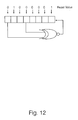
- FIG. 12 illustrates schematically a shift register arrangement according to a specific embodiment of the present invention, for generating a byte sequence as illustrated is FIG. 8 herein.
- the inventors have recognized that the constant frequency tones used in the preamble field of the known DDS-4 format devices have a different spectral power content to the user data in the data field. This is because the known preamble frequency tone comprises a sequence of bits +,+, ⁇ , ⁇ ,+,+, ⁇ , ⁇ and so on in the preamble region. Such a sequence has a fairly narrow power spectrum centered around a narrow frequency band.
- the user data in the data field has a power spectrum corresponding to a substantially random bit sequence
- the known constant frequency tone used in the preamble field of the DDS-4 format has a different spectral power characteristic.
- the user data is coded, such that it may appear random-like in nature.
- the minimum transition spacing physically recorded onto tape is of the order of 1T, and data exists in the user data area with spacings between transitions typically of 1T, 2T, 3T, 4T exclusively.
- the automatic gain control system In the read channel of a prior art DDS-4 device, the automatic gain control system has an effective frequency response which causes it to respond differently to the received channel amplitude of a constant tone, as compared to the received channel amplitude of a pseudo random sequence of bits as present in the user data field, even though the actual amplitude of bits in those fields may be the same.
- This causes the automatic gain control system to adjust the gain of the received channel, when in fact no effective change in received amplitude of individual bits has occurred.
- the adjustment may be of the order 0.8 to 1.2 dB, with DDS-1 to DDS-3 gain control systems, and in a DDS-4 system, in which a sample derived gain control system is used, the adjustment may be of order of 0.5 dB.
- the prior art DDS-4 read channel may not have an optimal gain for receiving bits of user data, for a period at the start of reading each user data field.
- the prior art gain control systems attempt to make a change in channel gain when experiencing a transition from the prior art preamble data to the prior art user data when in fact the amplitudes of the bits of those data remains constant.
- the preamble region 702 which is used to acquire gain and timing information by a read channel, is modified to contain a data sequence having the property that it is treated by an automatic gain control system of the read channel, as nearly as possible in the same way in which the automatic gain control system would treat a block of encoded user data in a user data field.
- the automatic gain control system maintains a stable pulse amplitude of bits entering the sequence detector.
- a byte sequence having power spectrum properties similar to a block of encoded user data is used. Over a large amount of user data, the user data on average will have a power spectrum equivalent to that of random data.
- the preamble data cannot be truly random, since it contains information enabling a synchronizer to lock onto it.
- the preamble data sequence must also have properties which allow a synchronization detector to synchronize quickly within a few T cycles to the preamble sequence.
- Several byte sequences may be suitable for such a preamble data sequence, however in the best mode herein the inventors have found that a byte sequence as illustrated in FIG. 8 herein has optimum properties.
- FIG. 8 there is illustrated schematically a byte sequence used in a preamble field of a logical data track according to a specific implementation of the present invention.
- the byte sequence illustrated in FIG. 8 is selected such as to have a power spectrum which matches closely a power spectrum of an average, or typical, sequence of user data bytes in the user data region 703 .
- the byte sequence passes through an 8-10 encoder prior to writing to tape.
- the preamble sequence of FIG. 8 can be applied at bit wave lengths as recorded on tape data storage medium having a T length of 125 nm, giving a total preamble region of 854 bits over a distance of 107 ⁇ m.
- the read or write heads are only linearly in physical contact with the tape for a finite distance either side of a center line 607 of the tape. It will be appreciated that the wavelength of bits may be varied without departing from the scope of the invention, and bit lengths in the range 100 nm to 140 nm may be suitable.
- the particular byte sequence illustrated in FIG. 8 is selected as a best mode byte sequence for reasons including the following:
- the spectrum of a received preamble signal at the preamplifier output of the read channel has no significant spectral holes in it. That is to say, there are no significant frequencies within the power spectrum of the output of the preamplifier, when reading the byte sequence of FIG. 8, which are absent or low.
- FIG. 9 there is illustrated a power spectrum 900 of a signal produced at the output of preamplifier 502 in the read channel when reading a preamble field 702 containing a byte sequence as illustrated in FIG. 8 herein. In the power spectrum of FIG.
- the distribution of power is centered around a mean value, and rolls off either side of the mean value without any significant troughs in power, over a range of frequencies between ⁇ 6 dB points either side of a peak value.
- the automatic gain control circuit reacts differently to the spectrum of a 2T constant tone than it does to the spectrum of random data.
- the presence of intersymbol interference in random data tends to make the average magnitude of a received +2 or ⁇ 2 signal slightly smaller than it should be, by up to 1 dB. This causes a small gain adjustment to be made by the automatic gain control circuit on reception of the first data fragment, even though there is no change in the amplitude of the bits of the incoming signal.
- the prior art preamble detector in conjunction with a prior art data recovery state machine is programmed such that as the break between preamble and random data in a user field is detected, a target level of the automatic gain control circuit system is immediately changed by a programmable amount in anticipation of a perceived change in incoming amplitude of user data.
- the prior art data recovery state machine is no longer capable of reliably spotting the boundary between the preamble data and the (random) user data.
- a chip containing the data recovery state machine must be operated in a non-optimal mode and is therefore susceptible to changes in perceived incoming signal amplitude.
- the result is that the inherent mismatch between the power spectrum of the prior art 2T preamble data field and the (random-like) user data field becomes more of a problem as data storage densities increase, and can prevent detection of the start of the user data field after detection of the preamble data.
- the user data is encoded using an 8-10 modulation encoder.
- the coding used in the 8-10 modulation has its own power spectrum characteristics. Over a large amount of user data, the user data is of a random-like nature and has a power spectrum characteristic corresponding substantially to a random bit sequence.
- the code used in the preamble region in the best mode is selected so as near as possible to have a power spectrum which is substantially the same as a power spectrum of an 8-10 modulation code power spectrum convolved with a power spectrum of a truly random bit sequence.
- phase information is produced in the byte sequence of FIG. 8 . It is important to have a sufficient number of valid transitions to allow a phase detector to maintain lock, or acquire lock under conditions of maximum noise.
- the preamble data sequence gives a number of transitions, which may be used for timing recovery. Only some of those transitions are useable by a timing circuit to acquire or maintain lock. Not all valid bit transitions contain phase information usable by a timing recovery loop circuit. Optimally, valid transitions would occur throughout the preamble region, so that lock could be acquired and/or maintained anywhere in the preamble data sequence.
- FIG. 10 illustrates a rolling deviation of a summed number of valid transitions from a summed average number of valid transitions per bit plotted against bit position within the preamble byte sequence in the preamble data region 702 .
- An ideal byte sequence would have an even distribution of transitions containing valid phase information, distributed between the first and last bytes of the preamble data sequence. Each end of the graph is therefore constrained to be ‘0’.
- the byte sequence of FIG. 8 gives rise to the transition distribution diagram of FIG. 10 showing a relatively constant distribution of transitions having valid phase information, which are relatively evenly distributed from bytes 0 to 853 of the preamble byte sequence, with only small peaks of density of transitions having valid phase information, constrained within + or ⁇ 6 transitions either side of a center value.
- some patterns have a peak deviation from a mean exceeding + or ⁇ 20 transitions either side of the peak.
- the preamble byte sequence is selected to have its last 8 bits corresponding to a 2T pattern. That is to say a pattern of 1,0,1,0,1,0,1,0. This gives a write current of 1,1, ⁇ 1, ⁇ 1,1,1, ⁇ 1,1,1. This is otherwise known as 2T. This may give a lowest possible intersymbol interference noise on entry into a first synchronization sequence 704 at the start of the user data region 703 , and therefore an enhanced probability of recovering the first synchronization sequence 704 in the user data region.
- the write channel comprises a header processor 1100 , for producing header data, including a preamble region, to prepend a user data region; an 8-10 encoder 1101 for encoding header data, including the preamble data and for encoding the user data, prior to recording onto tape; a non-return to 0 circuit 1102 ; an output amplifier 1103 for outputting a signal to a write head 1104 , which writes data to a magnetic tape data storage medium as a plurality of pulses, striped in a direction across a magnetic tape as in the prior art DDS-4 format.
- the header processor 1100 comprises a preamble field generator for generating a preamble data according to the byte sequence illustrated with reference to FIG. 8 herein.
- the preamble generator may be implemented as a shift register arrangement, in an application specific integrated circuit (ASIC), or may be implemented as a processor driven by software.
- ASIC application specific integrated circuit
- the shift register comprises an 8 bit register having an exclusive NOR gate (X-NOR) taking the output from locations 7 and 4 of the 8 bit register and feeding it back into a location 0 of the register.
- X-NOR exclusive NOR gate
- the first output from the linear feedback shift register is taken after 8 clock cycles, and should be the hex B3(h) byte. Successive outputs are taken after successive sets of 8 clock cycles.
- the shift register is reset to the value shown at the start of every track.
Landscapes
- Engineering & Computer Science (AREA)
- Signal Processing (AREA)
- Signal Processing For Digital Recording And Reproducing (AREA)
Priority Applications (1)
| Application Number | Priority Date | Filing Date | Title |
|---|---|---|---|
| US10/754,617 US7359132B2 (en) | 2000-04-10 | 2004-01-12 | Equalization preamble region in digital data storage (DDS) format |
Applications Claiming Priority (3)
| Application Number | Priority Date | Filing Date | Title |
|---|---|---|---|
| EP00303019A EP1146505B1 (en) | 2000-04-10 | 2000-04-10 | Equalization preamble region in digital data storage (DDS) format |
| EP00303019 | 2000-04-10 | ||
| EP00303019.4 | 2000-04-10 |
Related Child Applications (1)
| Application Number | Title | Priority Date | Filing Date |
|---|---|---|---|
| US10/754,617 Continuation-In-Part US7359132B2 (en) | 2000-04-10 | 2004-01-12 | Equalization preamble region in digital data storage (DDS) format |
Publications (2)
| Publication Number | Publication Date |
|---|---|
| US20010028521A1 US20010028521A1 (en) | 2001-10-11 |
| US6678104B2 true US6678104B2 (en) | 2004-01-13 |
Family
ID=8172906
Family Applications (1)
| Application Number | Title | Priority Date | Filing Date |
|---|---|---|---|
| US09/826,810 Expired - Fee Related US6678104B2 (en) | 2000-04-10 | 2001-04-06 | Equalization pre-amble region in digital data storage (DDS) format |
Country Status (4)
| Country | Link |
|---|---|
| US (1) | US6678104B2 (enExample) |
| EP (1) | EP1146505B1 (enExample) |
| JP (1) | JP4288019B2 (enExample) |
| DE (1) | DE60035178D1 (enExample) |
Cited By (1)
| Publication number | Priority date | Publication date | Assignee | Title |
|---|---|---|---|---|
| US20100007984A1 (en) * | 2008-07-11 | 2010-01-14 | Sony Corporation | Recording medium, recording apparatus, reproducing apparatus, and reproducing method |
Citations (5)
| Publication number | Priority date | Publication date | Assignee | Title |
|---|---|---|---|---|
| US3789377A (en) * | 1972-05-26 | 1974-01-29 | Lockheed Electronics Co | Pseudo-random sequence synchronization for magnetic recording system |
| JPH02177062A (ja) | 1988-12-27 | 1990-07-10 | Sony Corp | ディジタル情報信号記録装置 |
| US5349611A (en) * | 1992-11-13 | 1994-09-20 | Ampex Systems Corporation | Recovering synchronization in a data stream |
| EP0831480A1 (en) | 1996-09-24 | 1998-03-25 | Hewlett-Packard Company | Data processing apparatus and methods |
| US5841601A (en) | 1994-04-05 | 1998-11-24 | Quantum Corporation | Elimination of inter symbol interference-induced timing phase and gain steps at sector start in PRML digital magnetic data storage channel |
-
2000
- 2000-04-10 DE DE60035178T patent/DE60035178D1/de not_active Expired - Lifetime
- 2000-04-10 EP EP00303019A patent/EP1146505B1/en not_active Expired - Lifetime
-
2001
- 2001-04-06 US US09/826,810 patent/US6678104B2/en not_active Expired - Fee Related
- 2001-04-10 JP JP2001111308A patent/JP4288019B2/ja not_active Expired - Fee Related
Patent Citations (5)
| Publication number | Priority date | Publication date | Assignee | Title |
|---|---|---|---|---|
| US3789377A (en) * | 1972-05-26 | 1974-01-29 | Lockheed Electronics Co | Pseudo-random sequence synchronization for magnetic recording system |
| JPH02177062A (ja) | 1988-12-27 | 1990-07-10 | Sony Corp | ディジタル情報信号記録装置 |
| US5349611A (en) * | 1992-11-13 | 1994-09-20 | Ampex Systems Corporation | Recovering synchronization in a data stream |
| US5841601A (en) | 1994-04-05 | 1998-11-24 | Quantum Corporation | Elimination of inter symbol interference-induced timing phase and gain steps at sector start in PRML digital magnetic data storage channel |
| EP0831480A1 (en) | 1996-09-24 | 1998-03-25 | Hewlett-Packard Company | Data processing apparatus and methods |
Cited By (2)
| Publication number | Priority date | Publication date | Assignee | Title |
|---|---|---|---|---|
| US20100007984A1 (en) * | 2008-07-11 | 2010-01-14 | Sony Corporation | Recording medium, recording apparatus, reproducing apparatus, and reproducing method |
| US8111477B2 (en) * | 2008-07-11 | 2012-02-07 | Sony Corporation | Recording medium, recording apparatus, reproducing apparatus, and reproducing method |
Also Published As
| Publication number | Publication date |
|---|---|
| EP1146505B1 (en) | 2007-06-13 |
| JP2001357629A (ja) | 2001-12-26 |
| EP1146505A1 (en) | 2001-10-17 |
| US20010028521A1 (en) | 2001-10-11 |
| DE60035178D1 (de) | 2007-07-26 |
| JP4288019B2 (ja) | 2009-07-01 |
Similar Documents
| Publication | Publication Date | Title |
|---|---|---|
| EP0821828B1 (en) | Device for recording an information carrier, method and information carrier therefor | |
| EP0569610B1 (en) | Method and apparatus for determining the tape position for a tape using dedicated servo format | |
| US3623041A (en) | Method and apparatus for encoding and decoding digital data | |
| EP0492704A1 (en) | Arrangement for recording clock run-in codewords in a track on a magnetic record carrier | |
| US6167550A (en) | Write format for digital data storage | |
| JP2005525666A (ja) | データ・ストリームの同期および再同期のための方法、システム、およびプログラム | |
| US6338037B1 (en) | Audio signal identification using code labels inserted in the audio signal | |
| JPH0620401A (ja) | データ再生装置 | |
| US7359132B2 (en) | Equalization preamble region in digital data storage (DDS) format | |
| US6678104B2 (en) | Equalization pre-amble region in digital data storage (DDS) format | |
| EP0278702A2 (en) | Apparatus for reproducing a digital signal | |
| US6163421A (en) | Azimuth magnetic recording and reproducing apparatus and method employing waveform equalization | |
| US6543024B2 (en) | Write format for digital data storage | |
| JPH09505924A (ja) | 異なるビット密度で記録されたデータの再生 | |
| GB2192089A (en) | Method and apparatus for detecting a control system | |
| EP0650263A1 (en) | Coding and decoding methods and magnetic recording apparatus | |
| US20020003675A1 (en) | Signal processing circuit free from erroneuos data and the information storage apparatus including the signal processing circuit | |
| JP3678235B2 (ja) | 再生装置、再生方法 | |
| CA1307586C (en) | Apparatus for reproducing a digital signal | |
| EP0448370B1 (en) | Digital signal recording/reproducing system | |
| JP2529335B2 (ja) | ディジタル信号記録再生方式 | |
| EP1304684A2 (en) | Optimized data storage system and method for optical storage system | |
| KR100376392B1 (ko) | 데이터 기록 재생 장치 및 기록 매체 | |
| KR100776874B1 (ko) | 재생 장치 및 적응형 등화 회로 | |
| US5784215A (en) | Method and apparatus for recording and reading variable speed data using a rotating drum device |
Legal Events
| Date | Code | Title | Description |
|---|---|---|---|
| AS | Assignment |
Owner name: HEWLETT-PACKARD COMPANY, CALIFORNIA Free format text: ASSIGNMENT OF ASSIGNORS INTEREST;ASSIGNOR:HEWLETT-PACKARD LIMITED;REEL/FRAME:011698/0076 Effective date: 20010329 |
|
| AS | Assignment |
Owner name: HEWLETT-PACKARD DEVELOPMENT COMPANY L.P., TEXAS Free format text: ASSIGNMENT OF ASSIGNORS INTEREST;ASSIGNOR:HEWLETT-PACKARD COMPANY;REEL/FRAME:014061/0492 Effective date: 20030926 Owner name: HEWLETT-PACKARD DEVELOPMENT COMPANY L.P.,TEXAS Free format text: ASSIGNMENT OF ASSIGNORS INTEREST;ASSIGNOR:HEWLETT-PACKARD COMPANY;REEL/FRAME:014061/0492 Effective date: 20030926 |
|
| FPAY | Fee payment |
Year of fee payment: 4 |
|
| REMI | Maintenance fee reminder mailed | ||
| LAPS | Lapse for failure to pay maintenance fees | ||
| STCH | Information on status: patent discontinuation |
Free format text: PATENT EXPIRED DUE TO NONPAYMENT OF MAINTENANCE FEES UNDER 37 CFR 1.362 |
|
| FP | Lapsed due to failure to pay maintenance fee |
Effective date: 20120113 |