EP1146505B1 - Equalization preamble region in digital data storage (DDS) format - Google Patents
Equalization preamble region in digital data storage (DDS) format Download PDFInfo
- Publication number
- EP1146505B1 EP1146505B1 EP00303019A EP00303019A EP1146505B1 EP 1146505 B1 EP1146505 B1 EP 1146505B1 EP 00303019 A EP00303019 A EP 00303019A EP 00303019 A EP00303019 A EP 00303019A EP 1146505 B1 EP1146505 B1 EP 1146505B1
- Authority
- EP
- European Patent Office
- Prior art keywords
- data
- preamble
- power spectrum
- tape
- sequence
- Prior art date
- Legal status (The legal status is an assumption and is not a legal conclusion. Google has not performed a legal analysis and makes no representation as to the accuracy of the status listed.)
- Expired - Lifetime
Links
Images


Classifications
-
- G—PHYSICS
- G11—INFORMATION STORAGE
- G11B—INFORMATION STORAGE BASED ON RELATIVE MOVEMENT BETWEEN RECORD CARRIER AND TRANSDUCER
- G11B20/00—Signal processing not specific to the method of recording or reproducing; Circuits therefor
- G11B20/10—Digital recording or reproducing
-
- G—PHYSICS
- G11—INFORMATION STORAGE
- G11B—INFORMATION STORAGE BASED ON RELATIVE MOVEMENT BETWEEN RECORD CARRIER AND TRANSDUCER
- G11B20/00—Signal processing not specific to the method of recording or reproducing; Circuits therefor
- G11B20/10—Digital recording or reproducing
- G11B20/12—Formatting, e.g. arrangement of data block or words on the record carriers
- G11B20/1201—Formatting, e.g. arrangement of data block or words on the record carriers on tapes
-
- G—PHYSICS
- G11—INFORMATION STORAGE
- G11B—INFORMATION STORAGE BASED ON RELATIVE MOVEMENT BETWEEN RECORD CARRIER AND TRANSDUCER
- G11B2220/00—Record carriers by type
- G11B2220/90—Tape-like record carriers
- G11B2220/91—Helical scan format, wherein tracks are slightly tilted with respect to tape direction, e.g. VHS, DAT, DVC, AIT or exabyte
- G11B2220/916—Digital data storage [DDS] format
-
- G—PHYSICS
- G11—INFORMATION STORAGE
- G11B—INFORMATION STORAGE BASED ON RELATIVE MOVEMENT BETWEEN RECORD CARRIER AND TRANSDUCER
- G11B5/00—Recording by magnetisation or demagnetisation of a record carrier; Reproducing by magnetic means; Record carriers therefor
- G11B5/008—Recording on, or reproducing or erasing from, magnetic tapes, sheets, e.g. cards, or wires
- G11B5/00813—Recording on, or reproducing or erasing from, magnetic tapes, sheets, e.g. cards, or wires magnetic tapes
- G11B5/00847—Recording on, or reproducing or erasing from, magnetic tapes, sheets, e.g. cards, or wires magnetic tapes on transverse tracks
- G11B5/0086—Recording on, or reproducing or erasing from, magnetic tapes, sheets, e.g. cards, or wires magnetic tapes on transverse tracks using cyclically driven heads providing segmented tracks
-
- G—PHYSICS
- G11—INFORMATION STORAGE
- G11B—INFORMATION STORAGE BASED ON RELATIVE MOVEMENT BETWEEN RECORD CARRIER AND TRANSDUCER
- G11B5/00—Recording by magnetisation or demagnetisation of a record carrier; Reproducing by magnetic means; Record carriers therefor
- G11B5/02—Recording, reproducing, or erasing methods; Read, write or erase circuits therefor
- G11B5/09—Digital recording
Definitions
- the present invention relates to the field of data storage devices, and particularly, although not exclusively, to the field of digital data storage systems having a tape data storage medium which moves relative to a read/write head.
- DDS digital data storage
- an elongate band of magnetic tape contained upon a pair of spools in a data storage cassette is transported past one or more electromagnetic read and write heads, such that the rotating magnetic heads trace a path which is substantially diagonal across a main length of the elongate magnetic tape. Multiple passes of the write heads result in multiple diagonal tracks across the magnetic tape, which extend along a length of the magnetic tape.
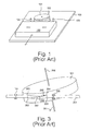
- FIG. 1 there is shown schematically a layout of a tape data storage cartridge in relation to a tape drive mechanism according to the DDS format, in which an elongate band of tape is contained within a removable tape cartridge 100.
- the tape cartridge is inserted into the tape drive mechanism.
- a rotating read/write head 101 comprises first and second read heads and first and second write heads situated at substantially equidistant points around a circumference of the rotating head.
- the head rotates on top of a substantially cylindrical metallic plinth 102.
- the read/write head rotates at a speed of approximately 11,400 revs per minute.
- a main central axis of a cylinder formed by the outer surfaces of the drum and the plinth is directed offset from a line normal to a plane of a base plate 103, so that the effect is that as the band of tape traverses around part of the circumference of the cylindrical head plinth, the rotating heads describe a path diagonally across the width of the tape in successive passes of the heads past the tape.
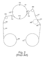
- FIG. 2 there is shown schematically a tape path of the elongate magnetic tape data storage medium 201 as it is drawn past the rotating drum containing the read and write heads.
- the tape data storage medium 201 is wound onto a feed reel 202 and a take up reel 203 which are within the removable tape cartridge 100.
- the magnetic tape 201 is wound from the feed-reel 202 on to the take-up reel 203.
- the path of the magnetic tape 201 is constrained by a plurality of rollers and tape guides 204-208. Additional tape guides 104, 105 determine the relative positions of the rotating drum 102, the read and write heads 210-213 and the tape data storage medium 201.
- the feed reel 202 and take up reel 203 are driven by electric motors to maintain a correct tension in the magnetic tape 201 past the head.
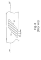
- FIG. 3 there is illustrated schematically the orientation of the magnetic tape 201 with respect to the rotating drum 101.
- the tape 201 is drawn past the rotating head at a relatively slow tape speed of the order of a few centimeters per second.
- the rotating drum 101 on which the read and write heads are mounted typically rotates at a few thousand revolutions per minute, so the relative speed of the read and write heads to the drum is of magnitudes of order greater than the absolute tape speed.
- the write heads record a sequence of tracks diagonally across the elongate magnetic tape 201. The width of such tracks is typically of the order of 6.8 ⁇ m.
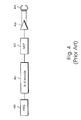
- the write circuit contains a linear feedback shift register 400 for generating a pseudo random bit sequence as described herein for incorporation into a preamble field of the logical data track; an 8-10 encoder 401; a non-return to zero circuit 402, an output amplifier 403, and a write head 404.
- a read channel for reading data from a data storage medium of cartridge 100.
- the read channel comprises a read head 500.
- Data stored on the tape is read by the read head 500 which passes the signal via a rotary transformer 501 to an amplifier 502.
- Amplifier 502 sends an amplified output signal which is input into an equalizer 503 for the purpose of initial equalization.
- the signal is passed into an automatic gain control circuit 504, and is filtered in a filter 505 which further shapes an overall channel frequency response to match a required equalization characteristic.
- the filtered signal is supplied to an analog to digital converter 506 which produces a digitized version of the filtered signal, which is then passed to a feed forward equalizer 507 which further equalizes the signal to a required equalization target.
- An equalized digital signal output from the feed forward equalizer 507 is input into a sequence detector 508.
- the sequence detector 508 includes a Viterbi engine, and various detection paths for determining a sequence of bits resulting from the signal read by the read head 500.
- the read channel also includes a preamble detector 509 for detecting preamble data before reading user data, the preamble detector producing an output which is set into a state machine 510. The output of the state machine controls automatic gain control circuit 504 to adjust a gain in the read channel.
- FIG. 6 there is illustrated schematically a layout of physical tracks striped across a width of an elongate magnetic band tape in a cartridge. A plurality of tracks are written slightly overlaying each other by successive passes of the write head of a rotating drum.
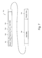
- the logical track 700 comprises at a start of the logical track, a first margin area 701 which when written physically resides at one edge of the tape data storage medium; a preamble region 702; a user data region 703, preceded by a synchronization header 704; and a second margin area 705 written after the user data 703, the second margin area laying physically at a second edge of the tape data storage medium.
- the preamble region is positioned between the first margin area 701 and the user data 703 and immediately preceding the user data 703.
- the purpose of the preamble region is acquire gain and timing information prior to reading the user data 703 with the object of achieving an optimum bit error rate in reading the user data area 703.
- the prior art preamble field contains a 2T tone data.
- the 2T tone data preamble field gives rise to a problem of fluctuation of gain control in the automatic gain control circuit 504 which becomes unacceptable for reading higher bit densities.
- the preamble region 702 usually consists of a single frequency constant tone bit sequence which immediately precedes the user data 703.
- the DDS-4 logical format calls for a constant 2T tone in the preamble region.
- the parameter T relates to the minimum acceptable spacing between pulse transitions.
- the preamble region 702 consists of 640 bits of data. The bits of data are arranged in transitions of 2T length, that is to say 4 bits per cycle. This gives a preamble region length of 160 cycles (640T), each cycle being +,+,-,-.
- the physical distance occupied by a cycle on the tape data storage medium depends upon the data storage density of bits on the tape.
- the overall physical length of preamble field as recorded onto tape in the DDS-4 format is approximately 107 ⁇ m.
- Preferably said preamble data sequence has a power spectrum having no significant troughs over a frequency band extending between first and second -6 dB power levels, each side of a peak value.
- preamble region (702) comprises between 800 and 900 bits per physical data track in a best mode implementation.
- Preferably said preamble data sequence has a power spectrum characteristic prior to any subsequent encoding which may occur, substantially similar to a power spectrum characteristic of the following byte stream b3, d2, b8, 83, 67, a5, 71, 06, cf, 4a, e2, 0d, 9e, 95, c4, 1b, 3d, 2b, 88, 36, 7a, 57, 10, 6c, f4, ae, 20, d9, e9, 5c, 41, b3, d2, b8, 83, 67, a5, 71, 06, cf, 4a, e2, 0d, 9e, 95, c4, 1b, 3d, 2b, 88, 36, 7a, 57, 10, 6c, f4, ae, 20, d9, e9, 5c, 41, b3, d2, b8, 83, 67, a5, 71, 06, cf, 4a, e2,
- Said preamble data may comprise bits, which when written to tape each occupy a length of the order of 100 to 140 nanometers per bit.
- the bits Preferably, the bits have a wavelength of approximately 125 nanometers.
- the preamble data sequence preferably has a uniform distribution of transitions having valid phase information, from which a timing circuit can recover timing data.
- the preamble data sequence may have a distribution of density of transitions having valid phase information which is free of peaks of transitions of more than + or - 6 in density.
- said plurality of data tracks are written across a width of said tape data storage medium in a direction transverse to a main length of said tape data storage medium.
- said preamble data sequence is coded prior to writing to tape, and said coded preamble sequence has a power spectrum substantially similar to a power spectrum of an 8-10 modulation coding convolved with a power spectrum of a substantially random data.
- the preamble data sequence has at least 8 bits corresponding to a 2T transition pattern, where a 1T transition comprises a minimum spacing between pulse transitions.
- an encoder device as claimed in claim 11.
- an apparatus for encoding a plurality of tracks of data for storage on a tape data storage medium comprising:
- said write channel is arranged to write between 800 and 900 bits of said preamble data sequence on each of said plurality of tracks.
- the apparatus may write a preamble data sequence having a power spectrum characteristic substantially similar to a power spectrum characteristic of the following byte stream; b3, d2, b8, 83, 67, a5, 71, 06, cf, 4a, e2, 0d, 9e, 95, c4, 1b, 3d, 2b, 88, 36, 7a, 57, 10, 6c, f4, ae, 20, d9, e9, 5c, 41, b3, d2, b8, 83, 67, a5, 71, 06, cf, 4a, e2, 0d, 9e, 95, c4, 1b, 3d, 2b, 88, 36, 7a, 57, 10, 6c, f4, ae, 20, d9, e9, 5c, 41, b3, d2, b8, 83, 67, a5, 71, 06, cf, 4a, e2, 0d, 9e, 95,
- Each said bit may occupy a length of the order 100 to 140 nanometers per bit.
- a distribution of transitions containing phase information validly useable by a timer circuit is preferably free of peaks of density of transitions of more than + or - 6 from a mean value.
- said plurality of data tracks are written across a width of said tape data storage medium in a direction transverse to a main length of said tape data storage medium.
- the apparatus comprises an 8-10 encoder for encoding said preamble data sequence, to result in a 8-10 encoded preamble data sequence having a power spectrum substantially similar to a power spectrum of an 8-10 coding convolved with a power spectrum of a substantially random data.
- the inventors have recognized that the constant frequency tones used in the preamble field of the known DDS-4 format devices have a different spectral power content to the user data in the data field. This is because the known preamble frequency tone comprises a sequence of bits +,+,-,-,+,+,-,- and so on in the preamble region. Such a sequence has a fairly narrow power spectrum centered around a narrow frequency band.
- the user data in the data field has a power spectrum corresponding to a substantially random bit sequence
- the known constant frequency tone used in the preamble field of the DDS-4 format has a different spectral power characteristic.
- the user data is coded, such that it may appear random-like in nature.
- the minimum transition spacing physically recorded onto tape is of the order of 1T, and data exists in the user data area with spacings between transitions typically of 1T, 2T, 3T, 4T exclusively.
- the automatic gain control system In the read channel of a prior art DDS-4 device, the automatic gain control system has an effective frequency response which causes it to respond differently to the received channel amplitude of a constant tone, as compared to the received channel amplitude of a pseudo random sequence of bits as present in the user data field, even though the actual amplitude of bits in those fields may be the same.
- This causes the automatic gain control system to adjust the gain of the received channel, when in fact no effective change in received amplitude of individual bits has occurred.
- the adjustment may be of the order 0.8 to 1.2 dB, with DDS-1 to DDS-3 gain control systems, and in a DDS-4 system, in which a sample derived gain control system is used, the adjustment may be of order of 0.5 dB.
- the prior art DDS-4 read channel may not have an optimal gain for receiving bits of user data, for a period at the start of reading each user data field.
- the prior art gain control systems attempt to make a change in channel gain when experiencing a transition from the prior art preamble data to the prior art user data when in fact the amplitudes of the bits of those data remains constant.
- the preamble region 702 which is used to acquire gain and timing information by a read channel, is modified to contain a data sequence having the property that it is treated by an automatic gain control system of the read channel, as nearly as possible in the same way in which the automatic gain control system would treat a block of encoded user data in a user data field.
- the automatic gain control system maintains a stable pulse amplitude of bits entering the sequence detector.
- a byte sequence having power spectrum properties similar to a block of encoded user data is used. Over a large amount of user data, the user data on average will have a power spectrum equivalent to that of random data.
- the preamble data cannot be truly random, since it contains information enabling a synchronizer to lock onto it.
- the preamble data sequence must also have properties which allow a synchronization detector to synchronize quickly within a few T cycles to the preamble sequence.
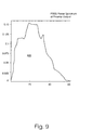
- Several byte sequences may be suitable for such a preamble data sequence, however in the best mode herein the inventors have found that a byte sequence as illustrated in Fig. 8 herein has optimum properties.
- Fig. 8 there is illustrated schematically a byte sequence used in a preamble field of a logical data track according to a specific implementation of the present invention.
- the byte sequence illustrated in Fig. 8 is selected such as to have a power spectrum which matches closely a power spectrum of an average, or typical, sequence of user data bytes in the user data region 703.
- the byte sequence passes through an 8-10 encoder prior to writing to tape.
- the preamble sequence of Fig. 8 can be applied at bit wave lengths as recorded on tape data storage medium having a T length of 125 nm, giving a total preamble region of 854 bits over a distance of 107 ⁇ m.
- the read or write heads are only linearly in physical contact with the tape for a finite distance either side of a center line 607 of the tape. It will be appreciated that the wavelength of bits may be varied without departing from the scope of the invention, and bit lengths in the range 100nm to 140 nm may be suitable.
- the particular byte sequence illustrated in Fig. 8 is selected as a best mode byte sequence for reasons including the following:
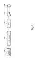
- the write channel comprises a header processor 1100, for producing header data, including a preamble region, to prepend a user data region; an 8-10 encoder 1101 for encoding header data, including the preamble data and for encoding the user data, prior to recording onto tape; a non-return to 0 circuit 1102; an output amplifier 1103 for outputting a signal to a write head 1104, which writes data to a magnetic tape data storage medium as a plurality of pulses, striped in a direction across a magnetic tape as in the prior art DDS-4 format.
- the header processor 1100 comprises a preamble field generator for generating a preamble data according to the byte sequence illustrated with reference to Fig. 8 herein.
- the preamble generator may be implemented as a shift register arrangement, in an application specific integrated circuit (ASIC), or may be implemented as a processor driven by software.
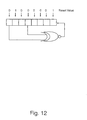
- a linear feedback shift register circuit capable of generating a pseudo random bit sequence as illustrated with reference to Fig. 8 herein.
- the shift register comprises an 8 bit register having an exclusive NOR gate (X-NOR) taking the output from locations 7 and 4 of the 8 bit register and feeding it back into a location 0 of the register.
- the first output from the linear feedback shift register is taken after 8 clock cycles, and should be the hex B3(h) byte. Successive outputs are taken after successive sets of 8 clock cycles.
- the shift register is reset to the value shown at the start of every track.
Landscapes
- Engineering & Computer Science (AREA)
- Signal Processing (AREA)
- Signal Processing For Digital Recording And Reproducing (AREA)
Priority Applications (5)
| Application Number | Priority Date | Filing Date | Title |
|---|---|---|---|
| EP00303019A EP1146505B1 (en) | 2000-04-10 | 2000-04-10 | Equalization preamble region in digital data storage (DDS) format |
| DE60035178T DE60035178D1 (de) | 2000-04-10 | 2000-04-10 | Entzerrungspräambelbereich für das "digital data storage" (DDS) Format |
| US09/826,810 US6678104B2 (en) | 2000-04-10 | 2001-04-06 | Equalization pre-amble region in digital data storage (DDS) format |
| JP2001111308A JP4288019B2 (ja) | 2000-04-10 | 2001-04-10 | データ・トラック符号化方法 |
| US10/754,617 US7359132B2 (en) | 2000-04-10 | 2004-01-12 | Equalization preamble region in digital data storage (DDS) format |
Applications Claiming Priority (1)
| Application Number | Priority Date | Filing Date | Title |
|---|---|---|---|
| EP00303019A EP1146505B1 (en) | 2000-04-10 | 2000-04-10 | Equalization preamble region in digital data storage (DDS) format |
Publications (2)
| Publication Number | Publication Date |
|---|---|
| EP1146505A1 EP1146505A1 (en) | 2001-10-17 |
| EP1146505B1 true EP1146505B1 (en) | 2007-06-13 |
Family
ID=8172906
Family Applications (1)
| Application Number | Title | Priority Date | Filing Date |
|---|---|---|---|
| EP00303019A Expired - Lifetime EP1146505B1 (en) | 2000-04-10 | 2000-04-10 | Equalization preamble region in digital data storage (DDS) format |
Country Status (4)
| Country | Link |
|---|---|
| US (1) | US6678104B2 (enExample) |
| EP (1) | EP1146505B1 (enExample) |
| JP (1) | JP4288019B2 (enExample) |
| DE (1) | DE60035178D1 (enExample) |
Families Citing this family (1)
| Publication number | Priority date | Publication date | Assignee | Title |
|---|---|---|---|---|
| US8111477B2 (en) * | 2008-07-11 | 2012-02-07 | Sony Corporation | Recording medium, recording apparatus, reproducing apparatus, and reproducing method |
Family Cites Families (5)
| Publication number | Priority date | Publication date | Assignee | Title |
|---|---|---|---|---|
| US3789377A (en) * | 1972-05-26 | 1974-01-29 | Lockheed Electronics Co | Pseudo-random sequence synchronization for magnetic recording system |
| JPH02177062A (ja) * | 1988-12-27 | 1990-07-10 | Sony Corp | ディジタル情報信号記録装置 |
| US5349611A (en) * | 1992-11-13 | 1994-09-20 | Ampex Systems Corporation | Recovering synchronization in a data stream |
| JP2715057B2 (ja) * | 1994-04-05 | 1998-02-16 | クウォンタム・コーポレイション | データ記憶装置においてアンダーシュート誘起タイミング位相ステップを排除する方法およびハードディスクドライブ |
| DE69620272T2 (de) * | 1996-09-24 | 2003-07-24 | Hewlett-Packard Co. (N.D.Ges.D.Staates Delaware), Palo Alto | Datenverabeitungsgerät und -verfahren |
-
2000
- 2000-04-10 DE DE60035178T patent/DE60035178D1/de not_active Expired - Lifetime
- 2000-04-10 EP EP00303019A patent/EP1146505B1/en not_active Expired - Lifetime
-
2001
- 2001-04-06 US US09/826,810 patent/US6678104B2/en not_active Expired - Fee Related
- 2001-04-10 JP JP2001111308A patent/JP4288019B2/ja not_active Expired - Fee Related
Also Published As
| Publication number | Publication date |
|---|---|
| US6678104B2 (en) | 2004-01-13 |
| JP2001357629A (ja) | 2001-12-26 |
| EP1146505A1 (en) | 2001-10-17 |
| US20010028521A1 (en) | 2001-10-11 |
| DE60035178D1 (de) | 2007-07-26 |
| JP4288019B2 (ja) | 2009-07-01 |
Similar Documents
| Publication | Publication Date | Title |
|---|---|---|
| JP4090501B2 (ja) | 情報担体に記録する装置及び方法並びにそのための情報担体 | |
| US3623041A (en) | Method and apparatus for encoding and decoding digital data | |
| SK280673B6 (sk) | Spôsob zaznamenávania číslicového signálu na magne | |
| US6177890B1 (en) | Technique for increasing information density in data storage devices by utilizing a high-efficiency encoding scheme | |
| US5600502A (en) | Elimination of inter symbol interference-induced timing phase steps at sector start in PRML digital magnetic data storage channel | |
| US6282042B1 (en) | Data processing apparatus and methods | |
| WO2003056557A2 (en) | Method, system, and program for synchronization and resynchronization of a data stream | |
| EP0030301A2 (en) | Magnetic-recording method and apparatus; magnetic record medium produced by such method and method of using such record medium | |
| JPH0620401A (ja) | データ再生装置 | |
| US6338037B1 (en) | Audio signal identification using code labels inserted in the audio signal | |
| US7359132B2 (en) | Equalization preamble region in digital data storage (DDS) format | |
| EP1146505B1 (en) | Equalization preamble region in digital data storage (DDS) format | |
| DE69409399T2 (de) | Lesen von mit unterschiedlichen schreibdichten gespeicherten daten | |
| EP0996114B1 (en) | Servo system and method with multiple phase clock | |
| US5426655A (en) | Method and apparatus for magnetic recording of data | |
| US20020003675A1 (en) | Signal processing circuit free from erroneuos data and the information storage apparatus including the signal processing circuit | |
| CA1307586C (en) | Apparatus for reproducing a digital signal | |
| JP2529335B2 (ja) | ディジタル信号記録再生方式 | |
| DE69801410T2 (de) | Aufnahmevorrichtung für digitale Signale und entsprechendes Verfahren | |
| KR100376392B1 (ko) | 데이터 기록 재생 장치 및 기록 매체 | |
| KR100776874B1 (ko) | 재생 장치 및 적응형 등화 회로 | |
| JP3302183B2 (ja) | トラッキング制御装置 | |
| EP0416563A2 (en) | Rotary head type magnetic tape recording and reproducing apparatus | |
| US5784215A (en) | Method and apparatus for recording and reading variable speed data using a rotating drum device | |
| GB1585268A (en) | Multiple track recording |
Legal Events
| Date | Code | Title | Description |
|---|---|---|---|
| PUAI | Public reference made under article 153(3) epc to a published international application that has entered the european phase |
Free format text: ORIGINAL CODE: 0009012 |
|
| AK | Designated contracting states |
Kind code of ref document: A1 Designated state(s): AT BE CH CY DE DK ES FI FR GB GR IE IT LI LU MC NL PT SE Kind code of ref document: A1 Designated state(s): DE FR GB |
|
| AX | Request for extension of the european patent |
Free format text: AL;LT;LV;MK;RO;SI |
|
| 17P | Request for examination filed |
Effective date: 20011015 |
|
| AKX | Designation fees paid |
Free format text: DE FR GB |
|
| GRAP | Despatch of communication of intention to grant a patent |
Free format text: ORIGINAL CODE: EPIDOSNIGR1 |
|
| GRAS | Grant fee paid |
Free format text: ORIGINAL CODE: EPIDOSNIGR3 |
|
| GRAA | (expected) grant |
Free format text: ORIGINAL CODE: 0009210 |
|
| AK | Designated contracting states |
Kind code of ref document: B1 Designated state(s): DE FR GB |
|
| REG | Reference to a national code |
Ref country code: GB Ref legal event code: FG4D |
|
| REF | Corresponds to: |
Ref document number: 60035178 Country of ref document: DE Date of ref document: 20070726 Kind code of ref document: P |
|
| EN | Fr: translation not filed | ||
| PLBE | No opposition filed within time limit |
Free format text: ORIGINAL CODE: 0009261 |
|
| STAA | Information on the status of an ep patent application or granted ep patent |
Free format text: STATUS: NO OPPOSITION FILED WITHIN TIME LIMIT |
|
| PG25 | Lapsed in a contracting state [announced via postgrant information from national office to epo] |
Ref country code: DE Free format text: LAPSE BECAUSE OF FAILURE TO SUBMIT A TRANSLATION OF THE DESCRIPTION OR TO PAY THE FEE WITHIN THE PRESCRIBED TIME-LIMIT Effective date: 20070914 |
|
| 26N | No opposition filed |
Effective date: 20080314 |
|
| PG25 | Lapsed in a contracting state [announced via postgrant information from national office to epo] |
Ref country code: FR Free format text: LAPSE BECAUSE OF FAILURE TO SUBMIT A TRANSLATION OF THE DESCRIPTION OR TO PAY THE FEE WITHIN THE PRESCRIBED TIME-LIMIT Effective date: 20080208 |
|
| PGFP | Annual fee paid to national office [announced via postgrant information from national office to epo] |
Ref country code: GB Payment date: 20100401 Year of fee payment: 11 |
|
| GBPC | Gb: european patent ceased through non-payment of renewal fee |
Effective date: 20110410 |
|
| PG25 | Lapsed in a contracting state [announced via postgrant information from national office to epo] |
Ref country code: GB Free format text: LAPSE BECAUSE OF NON-PAYMENT OF DUE FEES Effective date: 20110410 |