US6668155B1 - Lead edge paper curl sensor - Google Patents
Lead edge paper curl sensor Download PDFInfo
- Publication number
- US6668155B1 US6668155B1 US10/202,209 US20220902A US6668155B1 US 6668155 B1 US6668155 B1 US 6668155B1 US 20220902 A US20220902 A US 20220902A US 6668155 B1 US6668155 B1 US 6668155B1
- Authority
- US
- United States
- Prior art keywords
- sheet
- moving
- curl
- movement direction
- sensing
- Prior art date
- Legal status (The legal status is an assumption and is not a legal conclusion. Google has not performed a legal analysis and makes no representation as to the accuracy of the status listed.)
- Expired - Lifetime
Links
- 230000033001 locomotion Effects 0.000 claims abstract description 38
- 230000003287 optical effect Effects 0.000 claims abstract description 25
- 238000005259 measurement Methods 0.000 claims abstract description 22
- 238000006073 displacement reaction Methods 0.000 claims abstract description 17
- 238000000034 method Methods 0.000 claims abstract description 17
- 238000005286 illumination Methods 0.000 claims description 36
- 230000004044 response Effects 0.000 claims description 10
- 239000004909 Moisturizer Substances 0.000 claims description 4
- 230000002452 interceptive effect Effects 0.000 abstract 1
- 238000002310 reflectometry Methods 0.000 description 12
- 238000007639 printing Methods 0.000 description 11
- 230000032258 transport Effects 0.000 description 10
- 238000001514 detection method Methods 0.000 description 7
- 238000003384 imaging method Methods 0.000 description 6
- 230000008859 change Effects 0.000 description 5
- 238000012360 testing method Methods 0.000 description 4
- 239000000463 material Substances 0.000 description 3
- 210000001747 pupil Anatomy 0.000 description 3
- 230000035945 sensitivity Effects 0.000 description 3
- 239000007787 solid Substances 0.000 description 3
- 238000011144 upstream manufacturing Methods 0.000 description 3
- 238000013461 design Methods 0.000 description 2
- 230000008569 process Effects 0.000 description 2
- 238000012937 correction Methods 0.000 description 1
- 230000007423 decrease Effects 0.000 description 1
- 230000001934 delay Effects 0.000 description 1
- 238000001739 density measurement Methods 0.000 description 1
- 238000007641 inkjet printing Methods 0.000 description 1
- 238000012986 modification Methods 0.000 description 1
- 230000004048 modification Effects 0.000 description 1
- 238000001579 optical reflectometry Methods 0.000 description 1
- 230000035515 penetration Effects 0.000 description 1
- 238000010926 purge Methods 0.000 description 1
- 238000000926 separation method Methods 0.000 description 1
- 239000000758 substrate Substances 0.000 description 1
- XLYOFNOQVPJJNP-UHFFFAOYSA-N water Substances O XLYOFNOQVPJJNP-UHFFFAOYSA-N 0.000 description 1
- 238000009736 wetting Methods 0.000 description 1
Images


Classifications
-
- G—PHYSICS
- G03—PHOTOGRAPHY; CINEMATOGRAPHY; ANALOGOUS TECHNIQUES USING WAVES OTHER THAN OPTICAL WAVES; ELECTROGRAPHY; HOLOGRAPHY
- G03G—ELECTROGRAPHY; ELECTROPHOTOGRAPHY; MAGNETOGRAPHY
- G03G15/00—Apparatus for electrographic processes using a charge pattern
- G03G15/65—Apparatus which relate to the handling of copy material
- G03G15/6555—Handling of sheet copy material taking place in a specific part of the copy material feeding path
- G03G15/6573—Feeding path after the fixing point and up to the discharge tray or the finisher, e.g. special treatment of copy material to compensate for effects from the fixing
- G03G15/6576—Decurling of sheet material
Definitions
- Disclosed is a relatively low cost, simple, and non-contacting system for detecting or measuring either or both lead edge and trail edge curl of sheets, especially, print media sheets moving in a conventional paper transport path, which is easily mounted to conventional such sheet transport paths, and is fast enough in operation to provide “real time” measurement data which may be used to provide “on line” automatic control of various automatic sheet decurling systems.
- Disclosed in the embodiment herein is an improved system for measuring the amount of curl of an edge of a print media sheet moving through a printer or other media handling system.
- the disclosed system provides a novel optical reflectivity sensing system for providing an electrical output signal responsive to the curl of the paper or other sheet passing a relatively simple optical sensor in a sheet transport path with relatively uncritical confinement of the sheet being measured.
- the disclosed sheet curl sensing system embodiment is thus particularly suitable for the implementation of a “closed loop” curl detection plus curl correction system, by providing a more accurate curl detection signal in a high speed, on line manner, and without needing to contact the paper. Furthermore, this may be accomplished even though there is ink, toner, or other imaging material on the curled edge of the sheet, or with different color sheets. Further disclosed in the embodiment herein are displacement insensitive optics for this measurement, to render less critical the position of the sheet relative to the sensor, and thus allow more accurate sheet curl measurements to be made in various different normal, relatively unconfined, sheet transport paths.
- the curl detection signal may also be optionally used additionally or separately to control an automatic remoisturizer in the same paper path, such as between the fuser and the output tray, to remoisturize the sheet and thereby automatically additionally or alternatively reduce detected sheet curl.
- an automatic remoisturizer in the same paper path, such as between the fuser and the output tray, to remoisturize the sheet and thereby automatically additionally or alternatively reduce detected sheet curl.
- the amount of moisture in the sheet of paper can drastically change from the printing process itself, to cause or exacerbate curl.
- from water-based ink jet printing or the thermal fusing operation for toners in xerographic printing and particular from high density image printing near the edges of a sheet.
- decurlers with adjustable amounts of sheet decurling in the output of printers to at least partially correct or compensate for sheet curl.
- Some examples of automatic or manually adjusted sheet decurling systems include Xerox Corporation U.S. Pat. Nos.: 5,392,106; 5,515,152; 5,519,481; 5,539,511; 5,565,971; 5,848,347; 6,003,864; and 6,314,268. Note that while, for example, said U.S. Pat. No. 5,539,511 does not explicitly identify a control signal, it describes variable position decurling rollers with a position controlled by solenoid, screw drive, etc., according to the amount of expected sheet curl.
- Sheet remoisturizing systems are another alternative or additional known means for reducing sheet curl.
- Some examples of Xerox Corporation Patents on sheet remoisturizing or wetting systems include U.S. Pat. Nos.: 5,264,899; 5,850,589; 5,920,751; and 6,094,560 (the later also including decurling).
- the disclosed embodiment can provide an electrical output control signal proportional to the amount of detected curl of individual sheets upstream of an automatic sheet decurler and/or remoisturizer to provide such a control thereof.
- the disclosed exemplary sheet curl detection system is not limited to that particular application.
- Other applications will be apparent to those skilled in the printing or other sheet handling arts.
- a system of automatically diverting (with a sheet path gate to a “purge” tray output) a sheet detected as having an amount of curl above a safe sheet feeding level, in order to avoid Is potential sheet jams in downstream sheet transport paths, imaging stations or finishing operations.
- the present system should be distinguished from previous systems for detecting the position of the edge of a document with optical detectors and angled illumination to form edge shadows, such as Xerox Corporation U.S. Pat. Nos. 5,847,405 and 5,859,440. Likewise, the present system should be distinguished from photoelectric transmissive paper basis weight thickness or density measurement devices, such as Xerox Corporation U.S. Pat. No. 5,138,178.
- a specific feature of the specific embodiment disclosed herein is to provide a sheet curl sensing system for sensing the curl of a sheet moving in a movement direction in a sheet transport path, comprising an unobstructing non-contacting optical sheet curl sensor having a first sheet illuminator mounted to illuminate a portion of the moving sheet at an angle in a direction substantially parallel to said movement direction, a second sheet illuminator mounted to illuminate a portion of the moving sheet at an angle in a direction substantially transverse to said movement direction, and a photodetector system positioned to sense said illumination of the moving sheet by both said first and second sheet illuminators as said illumination is reflected approximately perpendicularly from said illuminated portion of the moving sheet and to provide variable output control signals in response to said sensed reflected illumination level.
- variable output control signals in response to said sensed reflected illumination are a ratio of the output control signals from said photodetector system produced by said first and second sheet illuminators; and/or an automatic sheet decurling system comprising a variable sheet decurler and/or re-moisturizer controlled by output control signals from an unobstructing non-contacting optical sheet curl sensor sensing the curl of a sheet moving in a movement direction in a sheet transport path towards said decurler and/or re-moisturizer, said optical sheet curl sensor comprising an unobstructing non-contacting optical sheet curl sensor having a first sheet illuminator mounted to illuminate a portion of the moving sheet at an angle in a direction substantially parallel to said movement direction, a second sheet illuminator mounted to illuminate a portion of the moving sheet at an angle in a direction substantially transverse to said movement direction, and a photodetector system positioned to sense said illumination of the moving sheet by both
- the disclosed system may be operated and controlled by appropriate operation of conventional control systems. It is well-known and preferable to program and execute, printing, paper handling, and other control functions and logic with software instructions for conventional or general purpose microprocessors, as taught by numerous prior patents and commercial products. Such programming or software may of course vary depending on the particular functions, software type, and microprocessor or other computer system utilized, but will be available to, or readily programmable without undue experimentation from, functional descriptions, such as those provided herein, and/or prior knowledge of functions which are conventional, together with general knowledge in the software or computer arts. Alternatively, the disclosed control system or method may be implemented partially or fully in hardware, using standard logic circuits or single chip VLSI designs.
- production apparatus or “printer” as used herein broadly encompasses various printers, copiers or multifunction machines or systems, xerographic or otherwise, unless otherwise defined in a claim.
- sheet herein refers to a usually flimsy physical sheet of paper, plastic, or other suitable physical substrate for images, whether precut or web fed and cut.
- a “copy sheet” may be abbreviated as a “copy” or called a “hardcopy.”
- a “print job” is normally a set of related sheets, usually one or more collated copy sets copied from a set of original document sheets or electronic document page images, from a particular user, or otherwise related.
- a “simplex” document or copy sheet is one having its image and any page number on only one side or face of the sheet, whereas a “duplex” document or copy sheet normally has images printed on both sides.
- FIG. 1 is a top view of an exemplary paper edge curl sensor, per se;
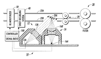
- FIG. 2 is a cross-sectional side view of the sheet curl sensor of FIG. 1 as shown mounted in an operating position relative to a portion of a conventional sheet path of a conventional xerographic printer, downstream of a conventional fuser and upstream of (and controlling) known sheet decurling and sheet remoisturing systems (all as in examples cited above, and therefor illustrated here schematically);
- FIG. 3 is a schematic side view of an optical layout of the sheet edge curl sensor of FIGS. 1 and 2;
- FIG. 4 is an exemplary graph plot for the two different exemplary sensor outputs for the two orthogonal sheet illuminators of FIGS. 1-3, to illustrate a comparison of the signals of those two channels versus the attitude of the paper being sensed;
- FIG. 5 is similar to FIG. 4, but showing the ratio of those two different sensor output signals as a function of paper attitude.
- the print media or other sheet of interest may be irradiated with light at an angle of approximately 45° and the reflectivity of that illumination is measured at approximately 0° with at least two channels.
- a first channel measures the reflectivity from the sheet perpendicular to the direction of motion of the print media
- another (second) channel measures the reflectivity from the sheet parallel to the direction of motion of the print media.
- the reflectivity measured by this second channel is more sensitive to the attitude of the paper, that is, the amount of lead edge curl of the paper.
- a measure of the lead edge curl may be made and provided as an output signal. Utilizing the ratio of these two signals desensitizes the measurement from the reflectivity of the sheet, since the sheet will have different reflectivity depending on the color of the sheet and whether there is imaging material (toner or ink) on the area of the sheet being illuminated at that point.
- the output of both measurement channels will be affected equally and the ratio will therefor not change.
- the measurement is also desensitized to the displacement of the sheet.
- the normal variations in the position of a sheet in the movement of the sheet along the sheet path between the normal spaced apart sheet path defining baffles This allows non-critical spacing of the exemplary sensor from the measured sheet and the mounting of the sensor outside the sheet path.
- FIG. 2 the document edge curl detector system of FIG. 1 is shown positioned below (but could also be above) a sheet of paper traveling through a sensing area.
- the sensing area may be provided, as here, from outside the sheet path though a small aperture in one of the conventional sheet baffles.
- This sensing area here is defined by two separate light beams sequentially orthogonally illuminating the sheet, including any curled edge area of the sheet, as the sheet is conventionally transported in the conventional sheet path past the small sensing area.
- the illumination does not need to be provided for the passage of the entire sheet. Continuous information as to the lead edge and trail edge position of a sheet in a printer sheet path is normally available from the printer controller. Thus, the illumination can be turned on, and sensing provided, only for the sheet lead edge and trail edge areas. Or, the sensor output signals blocked or ignored for any desired non-measurement time periods.
- measurement of the curl could improve the quality of the curl information and thus allow better control of the decurler.
- measurement of paper curl may be more accurate if it is timed by the printer controller 100 to the known sheet position when the lead edge of the sheet is extending a small defined distance downstream from one of the paper path sheet feed roller nips, as shown in FIG. 2, or the fuser rolls nip itself (which, of course is also a paper path sheet feeding nip). That is, measuring sheet lead edge curl when the sheet lead edge is extending from a sheet-holding nip by a known defined and relatively short distance (only a small portion of the sheet dimension).
- sensing could be provided for an entire sheet to also check for sheet cockleing, warping or buckling, as can occur in certain print media.
- FIGS. 1-3 there is illustrated an exemplary embodiment 10 of the subject document edge curl detector system.
- a lead edge curled up area 20 A of a sheet 20 is shown moving downstream in a conventional sheet path between conventional spaced apart baffles 22 A, 22 B, downstream of a conventional fuser 30 receiving sequential said sheets 20 from any conventional upstream xerographic or other printer (not illustrated).
- FIG. 2 illustrates the application of the output signals of the sheet curl detector 10 to control one or both of a sheet decurling system 40 and a sheet remoisturizer 50 through the existing controller 100 of the reproduction apparatus of this exemplary application.
- the controller 100 may, as indicated, perform the ratio operation providing the difference in output signal between FIGS. 4 and 5, for example.
- the exemplary sheet curl detector 10 may comprise two orthogonally mounted LED illumination systems 12 and 14 , both of which are designed to illuminate the test area of the sheet 20 at an angle of approximately 45°. That reflected light from the sheet 20 is then received by a photodetector system 16 here comprising a photosensor chip 16 A and lens 16 B.
- the two selectively operable light emitter (illumination) units 12 and 14 may be structurally identical other than their orientation at 90° to one another. That is, each of the units 12 may comprise an LED 12 A and lens 12 B and the unit 14 may comprise a LED 14 A and lens 14 B. These optics are further illustrated in the FIG. 3 schematic of this optical system. It provides displacement insensitive optics as further described in the above-cited Xerox Corporation U.S. Pat. No. 6,384,918, issued May 7, 2002 to Fred F. Hubble, III, et al.
- FIG. 4 refers to the outputs of the photodetector 16 A for “channel A” and “channel B.” These, it will be appreciated, are the respective outputs of the photosensor 16 A to the controller 100 when the lead edge of the sheet is respectively illuminated transversely to or parallel to the lead edge of the sheet.
- Channel A is the photosensor 16 A signal provided by the reflected illumination of the illumination unit 14 of FIG. 1
- the channel B signal is the output of the photosensor 16 A as receiving light reflected from the sheet 20 when that sheet is being illuminated by the illumination unit 12 , which is perpendicular to the lead edge of the sheet 20 .
- FIG. 5 represents the ratio of these outputs, which is desired as the control signal.
- the sheet curl sensing system 10 is shown positioned below the path of a sheet of paper travelling through a sensing area defined by two light beams and a common detector. Both light beams strike the paper at an angle of 45° to the normal, and detection is performed at 0° to the normal.
- One of the light beams is aligned substantially parallel to the lead edge of the paper and the other substantially perpendicular, and they are labeled respectively “channel A” and “channel B” in FIGS. 4 and 5.
- FIG. 2 is a more detailed layout view of the optical system.
- Channel A aligned parallel to a sheet curl exhibits a lower sensitivity
- Channel B exhibits higher sensitivity
- the ratio of the signals from channel B to those of channel A enables a more accurate measure of curl to be made.
- the basis of the differential responsivity may be explained as follows.
- the amount of light entering the projection (collection) optics is proportional to the irradiance of the paper, the reflectivity of the paper, and the solid angle subtended by the entrance pupil of the lens system.
- A area of the entrance pupil of the lens 16 B.
- the imaging optics If we design the imaging optics to project a 1:1 image of the paper onto the detector and choose a small detector that will be overfilled by the illuminated image, then the energy striking the detector will be to first order independent of the displacement between the paper and the sensor. This is so because the light energy from the test patch collected by the optics is proportional to the solid angle subtended by the projection lens. As the media to optic displacement, r, varies, the total energy in the image varies by the solid angle, which is proportional to r ⁇ 2 . Variation in the media to sensor spacing also affects the image size in a corresponding manner. For 1:1 imaging optics, magnification varies as the inverse of the displacement, r ⁇ 1 , which produces a change in the image area proportional to r ⁇ 2 .
- the image energy density i.e., energy per unit area
- the detector samples a fixed area within the image, its output is thereby made independent of spacing.
- the detector output thus becomes independent of r and depends only on the paper irradiance.
- the irradiance pattern on the paper is an elliptical oval defined by the intersection of the incident light beam and the surface of the paper. If the incident beam is circular of radius c, then the nominal irradiance is;
- b minor axis of the irradiance beam.
- ⁇ the angle between the incident beam and the paper, nominally 45°.
- c the diameter of the incident beam.
- ⁇ the angle between the incident beam and the paper, nominally 0°.
- I B ( P ⁇ sin(45) ⁇ cos(0)) ⁇ ( ⁇ c *2)
- I B ( P ⁇ sin(45+ ⁇ ) ⁇ cos(0)) ⁇ ( ⁇ c *2)
- ⁇ the amount of paper rotation introduced by the curl.
- I A ( P ⁇ sin(45) ⁇ cos(0)) ⁇ ( ⁇ c *2)
- I A ( P ⁇ sin(45) ⁇ cos(0+ ⁇ )) ⁇ ( ⁇ c *2)
- the technique is insensitive to the reflectivity of the paper because the ratio of the curl sensitive channel (B) to the curl insensitive channel (A) is used as the detection metric.
- the two signals are modulated together by the overall reflectivity of the document.
- the technique is also insensitive to localized reflectivity variations which may be caused, for example, by printing. This is so because the part of the illuminated area on the sheet imaged onto the detector is the same for both light beams.
- the two channels were easily read in 200 microseconds by pulsing the LED's at 200 mA and using a detector 2.7 mm square. If we consider even a high printing process speed of ⁇ 500 mm/second, then the separation between the site measured by channel A and that by channel B will be 0.05 mm, an insignificant amount.
- FIGS. 4 and 5 display some early test results.
- FIG. 4 shows the signals from the two channels as a function of sheet attitude. As expected from the first order considerations described above, channel A varies slowly and channel B varies more quickly as the target rotates away from its nominal, 0° position, and B increases for negative angles and decreases for positive.
- FIG. 5 shows the ratio of signal B divided by signal A, and this too behaves as expected, ⁇ 2.1% signal change per degree of curl.
- What has been disclosed in this example is a non contacting system and method of measuring the lead edge and/or trail edge curl or other non-planer surface irregularity of sheets, especially print media in the paper transport of various reprographic machines.
- the device is compact and small enough for ease of mounting in various sheet transports, and, as demonstrated above, fast enough to provide measurement data in “real time.”
Landscapes
- Physics & Mathematics (AREA)
- General Physics & Mathematics (AREA)
- Controlling Sheets Or Webs (AREA)
- Registering, Tensioning, Guiding Webs, And Rollers Therefor (AREA)
- Separation, Sorting, Adjustment, Or Bending Of Sheets To Be Conveyed (AREA)
Abstract
Description
| Curl Angle | Relative Irradiance (uW/mm*2) | Irradiance Ratio, |
| (degrees) | Channel A | Channel B | (IB ÷ IA) |
| −10 | 98.5 | 81.1 | 0.82 |
| −5 | 99.6 | 90.9 | 0.91 |
| 0 | 100.0 | 100.0 | 1.00 |
| +5 | 99.6 | 108.3 | 1.09 |
| +10 | 98.5 | 115.8 | 1.18 |
Claims (12)
Priority Applications (3)
| Application Number | Priority Date | Filing Date | Title |
|---|---|---|---|
| US10/202,209 US6668155B1 (en) | 2002-07-23 | 2002-07-23 | Lead edge paper curl sensor |
| CA002435403A CA2435403C (en) | 2002-07-23 | 2003-07-16 | Lead edge paper curl sensor |
| BR0302445-8A BR0302445A (en) | 2002-07-23 | 2003-07-22 | Paper Front Edge Curl Sensor |
Applications Claiming Priority (1)
| Application Number | Priority Date | Filing Date | Title |
|---|---|---|---|
| US10/202,209 US6668155B1 (en) | 2002-07-23 | 2002-07-23 | Lead edge paper curl sensor |
Publications (1)
| Publication Number | Publication Date |
|---|---|
| US6668155B1 true US6668155B1 (en) | 2003-12-23 |
Family
ID=29735402
Family Applications (1)
| Application Number | Title | Priority Date | Filing Date |
|---|---|---|---|
| US10/202,209 Expired - Lifetime US6668155B1 (en) | 2002-07-23 | 2002-07-23 | Lead edge paper curl sensor |
Country Status (3)
| Country | Link |
|---|---|
| US (1) | US6668155B1 (en) |
| BR (1) | BR0302445A (en) |
| CA (1) | CA2435403C (en) |
Cited By (25)
| Publication number | Priority date | Publication date | Assignee | Title |
|---|---|---|---|---|
| US20040262836A1 (en) * | 2003-06-24 | 2004-12-30 | Junichi Tamamoto | Sheet handling apparatus |
| US20060133867A1 (en) * | 2004-12-21 | 2006-06-22 | Lexmark International, Inc. | Method of preventing media wrinkling |
| US20060181006A1 (en) * | 2004-10-01 | 2006-08-17 | Canon Finetech Inc. | Sheet processing apparatus and image forming apparatus having the same |
| US20060221340A1 (en) * | 2005-04-01 | 2006-10-05 | Xerox Corporation | Online grey balance with dynamic highlight and shadow controls |
| US20060222257A1 (en) * | 2005-04-01 | 2006-10-05 | Xerox Corporation | TRC smoothing algorithm to improve image contours in 1D color controls |
| EP1764578A2 (en) | 2005-09-20 | 2007-03-21 | Mondi Business Paper Services AG | Method and apparataus for determining the curvature of a surface of a body, for example paper or cartoon |
| US20070158897A1 (en) * | 2006-01-06 | 2007-07-12 | Xerox Corporation | Automatically variably heated airflow for separation of humid coated paper print media |
| US20080018913A1 (en) * | 2006-07-20 | 2008-01-24 | Xerox Corporation | Lead edge sheet curl sensor |
| US20090256896A1 (en) * | 2008-04-09 | 2009-10-15 | Xerox Corporation | Ink-jet printer and method for decurling cut sheet media prior to ink-jet printing |
| US20100074642A1 (en) * | 2008-09-19 | 2010-03-25 | Kaoru Kataoka | Image forming apparatus employing fixing device and control method therefor |
| US20100086338A1 (en) * | 2008-10-02 | 2010-04-08 | Riso Kagaku Corporation | Transfer control mechanism for printer and transfer control method |
| US20110064424A1 (en) * | 2009-09-15 | 2011-03-17 | Xerox Corporation | Dynamic media thickness, curl sensing system |
| US20110196650A1 (en) * | 2010-02-05 | 2011-08-11 | Xerox Corporation | Dual cross beam sensor system and method for measuring lead edge and/or trail edge media curl |
| US20110228282A1 (en) * | 2010-03-16 | 2011-09-22 | Xerox Corporation | Method and system for calibrating a multiple-beam curvature/flatness sensor |
| US20120223116A1 (en) * | 2011-03-01 | 2012-09-06 | Xerox Corporation | Dual operation de-curler |
| EP2624058A1 (en) * | 2012-01-31 | 2013-08-07 | Ricoh Company Ltd. | Image forming apparatus and curl correcting method |
| US8737906B2 (en) | 2012-09-28 | 2014-05-27 | Xerox Corporation | Substrate media height measurement system and method |
| JP2015117984A (en) * | 2013-12-18 | 2015-06-25 | コニカミノルタ株式会社 | Sheet shape measurement apparatus and image forming apparatus |
| US9195183B2 (en) * | 2013-09-06 | 2015-11-24 | Ricoh Company, Ltd. | Image forming apparatus with conveyance unit to regulate passage of recording medium |
| US9341466B1 (en) | 2014-12-04 | 2016-05-17 | Xerox Corporation | Sheet height sensor using movable and stationary mirrors |
| JP2016218310A (en) * | 2015-05-22 | 2016-12-22 | 京セラドキュメントソリューションズ株式会社 | Image formation apparatus |
| US9604478B1 (en) * | 2016-06-16 | 2017-03-28 | Xerox Corporation | Print media beam strength sensor |
| US10040299B2 (en) | 2013-01-25 | 2018-08-07 | Hewlett-Packard Development Company, L.P. | Printing apparatus and printing methods |
| CN111356593A (en) * | 2017-11-20 | 2020-06-30 | 惠普发展公司,有限责任合伙企业 | Media sensing |
| US11221579B2 (en) * | 2018-11-05 | 2022-01-11 | Xerox Corporation | System, apparatus, and method for printing large format media and targeted decurling of various printing processes |
Citations (13)
| Publication number | Priority date | Publication date | Assignee | Title |
|---|---|---|---|---|
| US5138178A (en) | 1990-12-17 | 1992-08-11 | Xerox Corporation | Photoelectric paper basis weight sensor |
| US5144385A (en) * | 1990-11-29 | 1992-09-01 | Ricoh Company, Ltd. | Curl removing device for an image recorder |
| US5539511A (en) | 1994-12-16 | 1996-07-23 | Xerox Corporation | Multilevel/duplex image sheet decurling apparatus |
| JPH08198477A (en) * | 1995-01-27 | 1996-08-06 | Hitachi Koki Co Ltd | Electrophotographic device |
| JPH096073A (en) * | 1995-06-14 | 1997-01-10 | Ricoh Co Ltd | Image forming device |
| JPH1077152A (en) * | 1996-09-02 | 1998-03-24 | Canon Inc | Curl correcting device, image forming device and curl detecting device |
| JPH10123781A (en) * | 1996-10-23 | 1998-05-15 | Mita Ind Co Ltd | Image forming device |
| US5787331A (en) * | 1994-12-14 | 1998-07-28 | Canon Kabushiki Kaisha | Curl correction device of an image forming apparatus |
| US5847405A (en) | 1997-09-04 | 1998-12-08 | Xerox Corporation | Size or position sensing of intermixed sheets in a sheet stacking tray with sheet edge shadow detection |
| US5859440A (en) | 1997-09-04 | 1999-01-12 | Xerox Corporation | Transparency sheet edge detector system using edge shadow sensing |
| US6094560A (en) | 1999-08-04 | 2000-07-25 | Xerox Corporation | Electrophotographic printing machine including a post-fusing substrate moisturizing and decurling device |
| US6351308B1 (en) | 1999-11-24 | 2002-02-26 | Xerox Corporation | Color printer color control system with automatic spectrophotometer calibration system |
| US6384918B1 (en) | 1999-11-24 | 2002-05-07 | Xerox Corporation | Spectrophotometer for color printer color control with displacement insensitive optics |
-
2002
- 2002-07-23 US US10/202,209 patent/US6668155B1/en not_active Expired - Lifetime
-
2003
- 2003-07-16 CA CA002435403A patent/CA2435403C/en not_active Expired - Fee Related
- 2003-07-22 BR BR0302445-8A patent/BR0302445A/en not_active Application Discontinuation
Patent Citations (13)
| Publication number | Priority date | Publication date | Assignee | Title |
|---|---|---|---|---|
| US5144385A (en) * | 1990-11-29 | 1992-09-01 | Ricoh Company, Ltd. | Curl removing device for an image recorder |
| US5138178A (en) | 1990-12-17 | 1992-08-11 | Xerox Corporation | Photoelectric paper basis weight sensor |
| US5787331A (en) * | 1994-12-14 | 1998-07-28 | Canon Kabushiki Kaisha | Curl correction device of an image forming apparatus |
| US5539511A (en) | 1994-12-16 | 1996-07-23 | Xerox Corporation | Multilevel/duplex image sheet decurling apparatus |
| JPH08198477A (en) * | 1995-01-27 | 1996-08-06 | Hitachi Koki Co Ltd | Electrophotographic device |
| JPH096073A (en) * | 1995-06-14 | 1997-01-10 | Ricoh Co Ltd | Image forming device |
| JPH1077152A (en) * | 1996-09-02 | 1998-03-24 | Canon Inc | Curl correcting device, image forming device and curl detecting device |
| JPH10123781A (en) * | 1996-10-23 | 1998-05-15 | Mita Ind Co Ltd | Image forming device |
| US5847405A (en) | 1997-09-04 | 1998-12-08 | Xerox Corporation | Size or position sensing of intermixed sheets in a sheet stacking tray with sheet edge shadow detection |
| US5859440A (en) | 1997-09-04 | 1999-01-12 | Xerox Corporation | Transparency sheet edge detector system using edge shadow sensing |
| US6094560A (en) | 1999-08-04 | 2000-07-25 | Xerox Corporation | Electrophotographic printing machine including a post-fusing substrate moisturizing and decurling device |
| US6351308B1 (en) | 1999-11-24 | 2002-02-26 | Xerox Corporation | Color printer color control system with automatic spectrophotometer calibration system |
| US6384918B1 (en) | 1999-11-24 | 2002-05-07 | Xerox Corporation | Spectrophotometer for color printer color control with displacement insensitive optics |
Cited By (46)
| Publication number | Priority date | Publication date | Assignee | Title |
|---|---|---|---|---|
| US8091888B2 (en) * | 2003-06-24 | 2012-01-10 | Hitachi-Omron Terminal Solutions Corp. | Sheet handling apparatus |
| US20040262836A1 (en) * | 2003-06-24 | 2004-12-30 | Junichi Tamamoto | Sheet handling apparatus |
| US20060181006A1 (en) * | 2004-10-01 | 2006-08-17 | Canon Finetech Inc. | Sheet processing apparatus and image forming apparatus having the same |
| US7665730B2 (en) * | 2004-10-01 | 2010-02-23 | Canon Finetech Inc. | Sheet processing apparatus and image forming apparatus having the same |
| US20100096800A1 (en) * | 2004-10-01 | 2010-04-22 | Canon Finetech Inc. | Sheet processing apparatus and image forming apparatus having the same |
| US8113513B2 (en) | 2004-10-01 | 2012-02-14 | Canon Finetech Inc. | Sheet processing apparatus with cross-directionally moving device |
| US20060133867A1 (en) * | 2004-12-21 | 2006-06-22 | Lexmark International, Inc. | Method of preventing media wrinkling |
| US7403737B2 (en) | 2004-12-21 | 2008-07-22 | Lexmark International, Inc. | Method of preventing media wrinkling |
| US20060221340A1 (en) * | 2005-04-01 | 2006-10-05 | Xerox Corporation | Online grey balance with dynamic highlight and shadow controls |
| US7397581B2 (en) | 2005-04-01 | 2008-07-08 | Xerox Corporation | TRC smoothing algorithm to improve image contours in 1D color controls |
| US20060222257A1 (en) * | 2005-04-01 | 2006-10-05 | Xerox Corporation | TRC smoothing algorithm to improve image contours in 1D color controls |
| EP1764578A2 (en) | 2005-09-20 | 2007-03-21 | Mondi Business Paper Services AG | Method and apparataus for determining the curvature of a surface of a body, for example paper or cartoon |
| US20070158897A1 (en) * | 2006-01-06 | 2007-07-12 | Xerox Corporation | Automatically variably heated airflow for separation of humid coated paper print media |
| US7445205B2 (en) | 2006-01-06 | 2008-11-04 | Xerox Corporation | Automatically variably heated airflow for separation of humid coated paper print media |
| US7548316B2 (en) | 2006-07-20 | 2009-06-16 | Xerox Corporation | System and method for lead edge and trail edge sheet constraint and curl sensing |
| US7545519B2 (en) | 2006-07-20 | 2009-06-09 | Xerox Corporation | Lead edge sheet curl sensor |
| US20080018913A1 (en) * | 2006-07-20 | 2008-01-24 | Xerox Corporation | Lead edge sheet curl sensor |
| US20080019751A1 (en) * | 2006-07-20 | 2008-01-24 | Ruddy Castillo | System and method for lead edge and trail edge sheet constraint and curl sensing |
| JP2008024518A (en) * | 2006-07-20 | 2008-02-07 | Xerox Corp | Sensor device and detection method for detecting curl of sheet front edge |
| US8038280B2 (en) * | 2008-04-09 | 2011-10-18 | Xerox Corporation | Ink-jet printer and method for decurling cut sheet media prior to ink-jet printing |
| US20090256896A1 (en) * | 2008-04-09 | 2009-10-15 | Xerox Corporation | Ink-jet printer and method for decurling cut sheet media prior to ink-jet printing |
| US8190046B2 (en) * | 2008-09-19 | 2012-05-29 | Ricoh Company, Limited | Image forming apparatus employing fixing device and control method therefor |
| US20100074642A1 (en) * | 2008-09-19 | 2010-03-25 | Kaoru Kataoka | Image forming apparatus employing fixing device and control method therefor |
| US20100086338A1 (en) * | 2008-10-02 | 2010-04-08 | Riso Kagaku Corporation | Transfer control mechanism for printer and transfer control method |
| US8346154B2 (en) * | 2008-10-02 | 2013-01-01 | Riso Kagaku Corporation | Transfer control mechanism for printer and transfer control method |
| US20110064424A1 (en) * | 2009-09-15 | 2011-03-17 | Xerox Corporation | Dynamic media thickness, curl sensing system |
| EP2299330A3 (en) * | 2009-09-15 | 2012-03-14 | Xerox Corporation | Dynamic media thickness, curl sensing system |
| US20110196650A1 (en) * | 2010-02-05 | 2011-08-11 | Xerox Corporation | Dual cross beam sensor system and method for measuring lead edge and/or trail edge media curl |
| US8234092B2 (en) | 2010-02-05 | 2012-07-31 | Xerox Corporation | Dual cross beam sensor system and method for measuring lead edge and/or trail edge media curl |
| US20110228282A1 (en) * | 2010-03-16 | 2011-09-22 | Xerox Corporation | Method and system for calibrating a multiple-beam curvature/flatness sensor |
| US8310660B2 (en) | 2010-03-16 | 2012-11-13 | Xerox Corporation | Method and system for calibrating a multiple-beam curvature/flatness sensor |
| US20120223116A1 (en) * | 2011-03-01 | 2012-09-06 | Xerox Corporation | Dual operation de-curler |
| US8795571B2 (en) * | 2011-03-01 | 2014-08-05 | Xerox Corporation | Dual operation de-curler |
| EP2624058A1 (en) * | 2012-01-31 | 2013-08-07 | Ricoh Company Ltd. | Image forming apparatus and curl correcting method |
| US9031492B2 (en) | 2012-01-31 | 2015-05-12 | Ricoh Company, Limited | Image forming apparatus and curl correcting method |
| US8737906B2 (en) | 2012-09-28 | 2014-05-27 | Xerox Corporation | Substrate media height measurement system and method |
| US10040299B2 (en) | 2013-01-25 | 2018-08-07 | Hewlett-Packard Development Company, L.P. | Printing apparatus and printing methods |
| US9195183B2 (en) * | 2013-09-06 | 2015-11-24 | Ricoh Company, Ltd. | Image forming apparatus with conveyance unit to regulate passage of recording medium |
| JP2015117984A (en) * | 2013-12-18 | 2015-06-25 | コニカミノルタ株式会社 | Sheet shape measurement apparatus and image forming apparatus |
| US9341466B1 (en) | 2014-12-04 | 2016-05-17 | Xerox Corporation | Sheet height sensor using movable and stationary mirrors |
| JP2016218310A (en) * | 2015-05-22 | 2016-12-22 | 京セラドキュメントソリューションズ株式会社 | Image formation apparatus |
| US9604478B1 (en) * | 2016-06-16 | 2017-03-28 | Xerox Corporation | Print media beam strength sensor |
| CN111356593A (en) * | 2017-11-20 | 2020-06-30 | 惠普发展公司,有限责任合伙企业 | Media sensing |
| EP3713770A4 (en) * | 2017-11-20 | 2021-06-30 | Hewlett-Packard Development Company, L.P. | Media sensing |
| US11220119B2 (en) | 2017-11-20 | 2022-01-11 | Hewlett-Packard Development Company, L.P. | Media sensing |
| US11221579B2 (en) * | 2018-11-05 | 2022-01-11 | Xerox Corporation | System, apparatus, and method for printing large format media and targeted decurling of various printing processes |
Also Published As
| Publication number | Publication date |
|---|---|
| CA2435403A1 (en) | 2004-01-23 |
| CA2435403C (en) | 2007-01-02 |
| BR0302445A (en) | 2004-08-24 |
Similar Documents
| Publication | Publication Date | Title |
|---|---|---|
| US6668155B1 (en) | Lead edge paper curl sensor | |
| US7545519B2 (en) | Lead edge sheet curl sensor | |
| JP3354978B2 (en) | Media sheet position determination device | |
| JP4663407B2 (en) | Recording material discrimination device and method | |
| JP5404323B2 (en) | Image forming apparatus | |
| CN100549850C (en) | Sheet feeding-device and imaging device | |
| US20090033030A1 (en) | Sheet conveying apparatus and image forming apparatus | |
| US6895210B1 (en) | Sheet to sheet, “on the fly” electronic skew correction | |
| JP2009037128A (en) | Image forming apparatus | |
| JP4654696B2 (en) | Paper judging method and paper measuring device | |
| US5329338A (en) | Optical transparency detection and discrimination in an electronic reprographic printing system | |
| JPH1077152A (en) | Curl correcting device, image forming device and curl detecting device | |
| JP4032895B2 (en) | Image forming apparatus | |
| US5831741A (en) | Method and apparatus for detecting holes in copy media | |
| JP5864997B2 (en) | Recording material discrimination apparatus and image forming apparatus | |
| US8234092B2 (en) | Dual cross beam sensor system and method for measuring lead edge and/or trail edge media curl | |
| US8213815B2 (en) | Image forming apparatus | |
| JP3882533B2 (en) | Paper conveying apparatus and image forming apparatus | |
| US7147222B2 (en) | Method and apparatus for registering sheet of arbitrary size | |
| JPH09278252A (en) | Image forming device | |
| JP2007304285A (en) | Image forming apparatus, moisture content detector and sensor for image forming apparatus | |
| JP5721871B2 (en) | Sheet conveying apparatus and image forming apparatus | |
| JP2003312894A (en) | Sheet carrying device and image forming device | |
| JP4757135B2 (en) | Sheet material conveying apparatus and image forming apparatus | |
| JP6039788B2 (en) | Recording material detection apparatus and image forming apparatus |
Legal Events
| Date | Code | Title | Description |
|---|---|---|---|
| AS | Assignment |
Owner name: XEROX CORPORATION, CONNECTICUT Free format text: ASSIGNMENT OF ASSIGNORS INTEREST;ASSIGNORS:HUBBLE, III., FRED F.;LOVE, TONYA L.;ROBBINS, DANIEL A.;AND OTHERS;REEL/FRAME:013144/0867;SIGNING DATES FROM 20020717 TO 20020718 |
|
| AS | Assignment |
Owner name: JPMORGAN CHASE BANK, AS COLLATERAL AGENT, TEXAS Free format text: SECURITY AGREEMENT;ASSIGNOR:XEROX CORPORATION;REEL/FRAME:015134/0476 Effective date: 20030625 Owner name: JPMORGAN CHASE BANK, AS COLLATERAL AGENT,TEXAS Free format text: SECURITY AGREEMENT;ASSIGNOR:XEROX CORPORATION;REEL/FRAME:015134/0476 Effective date: 20030625 |
|
| STCF | Information on status: patent grant |
Free format text: PATENTED CASE |
|
| AS | Assignment |
Owner name: JPMORGAN CHASE BANK, AS COLLATERAL AGENT, TEXAS Free format text: SECURITY AGREEMENT;ASSIGNOR:XEROX CORPORATION;REEL/FRAME:015722/0119 Effective date: 20030625 Owner name: JPMORGAN CHASE BANK, AS COLLATERAL AGENT,TEXAS Free format text: SECURITY AGREEMENT;ASSIGNOR:XEROX CORPORATION;REEL/FRAME:015722/0119 Effective date: 20030625 |
|
| FPAY | Fee payment |
Year of fee payment: 4 |
|
| FPAY | Fee payment |
Year of fee payment: 8 |
|
| FPAY | Fee payment |
Year of fee payment: 12 |
|
| AS | Assignment |
Owner name: XEROX CORPORATION, CONNECTICUT Free format text: RELEASE BY SECURED PARTY;ASSIGNOR:JPMORGAN CHASE BANK, N.A. AS SUCCESSOR-IN-INTEREST ADMINISTRATIVE AGENT AND COLLATERAL AGENT TO BANK ONE, N.A.;REEL/FRAME:061360/0501 Effective date: 20220822 |
|
| AS | Assignment |
Owner name: XEROX CORPORATION, CONNECTICUT Free format text: RELEASE BY SECURED PARTY;ASSIGNOR:JPMORGAN CHASE BANK, N.A. AS SUCCESSOR-IN-INTEREST ADMINISTRATIVE AGENT AND COLLATERAL AGENT TO JPMORGAN CHASE BANK;REEL/FRAME:066728/0193 Effective date: 20220822 |
|
| AS | Assignment |
Owner name: CITIBANK, N.A., AS AGENT, DELAWARE Free format text: SECURITY INTEREST;ASSIGNOR:XEROX CORPORATION;REEL/FRAME:062740/0214 Effective date: 20221107 |
|
| AS | Assignment |
Owner name: XEROX CORPORATION, CONNECTICUT Free format text: RELEASE OF SECURITY INTEREST IN PATENTS AT R/F 062740/0214;ASSIGNOR:CITIBANK, N.A., AS AGENT;REEL/FRAME:063694/0122 Effective date: 20230517 |