JP5404323B2 - Image forming apparatus - Google Patents
Image forming apparatus Download PDFInfo
- Publication number
- JP5404323B2 JP5404323B2 JP2009253016A JP2009253016A JP5404323B2 JP 5404323 B2 JP5404323 B2 JP 5404323B2 JP 2009253016 A JP2009253016 A JP 2009253016A JP 2009253016 A JP2009253016 A JP 2009253016A JP 5404323 B2 JP5404323 B2 JP 5404323B2
- Authority
- JP
- Japan
- Prior art keywords
- transfer material
- image forming
- forming apparatus
- angle
- reference side
- Prior art date
- Legal status (The legal status is an assumption and is not a legal conclusion. Google has not performed a legal analysis and makes no representation as to the accuracy of the status listed.)
- Expired - Fee Related
Links
Images


Landscapes
- Paper Feeding For Electrophotography (AREA)
- Controlling Sheets Or Webs (AREA)
- Registering Or Overturning Sheets (AREA)
Description
本発明は、複写機、プリンタ、印刷機などに代表される画像形成装置に関し、特に、搬送される転写材のある一辺を基準辺として斜行補正を行う画像形成装置に関する。 The present invention relates to an image forming apparatus typified by a copying machine, a printer, a printing machine, and the like, and more particularly, to an image forming apparatus that performs skew correction using one side of a transfer material to be conveyed as a reference side.
画像形成装置において紙などの転写材を搬送する場合、搬送中に発生する転写材の斜行や位置ズレは、搬送ジャムや下流側の搬送ローラへの受け渡し不良、また転写材表面に印字などを行う場合には印字精度の低下などの問題を招く。そのため、従来の画像形成装置は何らかの方式の斜行補正手段を備えており、一般的には転写材表面に画像が転写される直前に斜行補正手段を設けることで、転写材と画像の位置合わせをより精度良く行っている。具体的には、図1に示した画像形成装置60における二次転写部の直前に設けられたレジストレーション装置65がこれに相当する。
When a transfer material such as paper is transported in an image forming apparatus, the skew or misalignment of the transfer material that occurs during transport is caused by poor delivery to the transport jam or the downstream transport roller, or printing on the surface of the transfer material. If it is performed, problems such as a decrease in printing accuracy are caused. For this reason, the conventional image forming apparatus is provided with some type of skew feeding correcting means. Generally, by providing the skew feeding correcting means immediately before the image is transferred onto the surface of the transfer material, the position of the transfer material and the image is determined. Matching is performed with higher accuracy. Specifically, the
レジストレーション装置にはいくつかの方式があり、代表的なものに斜送レジストレーション方式、アクティブレジストレーション方式、シャッターレジストレーション方式などがある。 There are several types of registration apparatuses, and representative ones include an oblique registration method, an active registration method, and a shutter registration method.
斜送レジストレーション方式の装置は、転写材の搬送方向に対して所定角度だけ傾けて配置された斜送ローラ対と、該斜送ローラ対によって搬送される転写材の基準辺を突き当てるための突き当て基準部材を備えている。そして、斜行補正における基準辺は搬送方向の辺(サイド辺)である。また、アクティブレジストレーション方式の装置及びシャッターレジストレーション方式の装置においても、斜行補正における基準辺は幅方向の辺(トップ辺)である。したがって、基準辺を用いて斜行補正を行うためには高い精度が要求され、特に基準辺の傾きは、転写材に画像が形成される際の余白に大きく影響を及ぼすため重要な要素となる。この斜行補正の精度を向上させるために、従来の画像形成装置、例えば前記斜送レジストレーション方式の画像形成装置としては、突き当て基準部材の角度を可変に構成したものが知られている。この従来の画像形成装置では、突き当て基準部材の角度を調整することにより、転写材と画像の相対的な傾き関係を最小にしようとしている(例えば、特許文献1および2参照)。
The skew feeding registration type apparatus is configured to abut a reference feeding roller pair disposed at an angle with respect to a transfer material conveyance direction and a reference side of the transfer material conveyed by the skew feeding roller pair. An abutting reference member is provided. The reference side in the skew correction is a side in the transport direction (side side). Also, in the active registration type apparatus and the shutter registration type apparatus, the reference side in the skew correction is the side in the width direction (top side). Therefore, high accuracy is required to perform skew correction using the reference side, and in particular, the inclination of the reference side is an important factor because it greatly affects the margin when an image is formed on a transfer material. . In order to improve the accuracy of the skew feeding correction, as a conventional image forming apparatus, for example, an image forming apparatus using the skew feeding registration method, an apparatus in which the angle of the abutting reference member is variable is known. This conventional image forming apparatus attempts to minimize the relative inclination relationship between the transfer material and the image by adjusting the angle of the abutting reference member (see, for example,
しかし、実際に転写材と画像の相対的な傾き関係に影響を与えている要因は、前記突き当て基準部材の平行度や直角度の精度だけでなく、転写材自体の断裁精度も挙げられる。転写材のある一辺を基準辺とするレジストレーション方式では、転写材の断裁が直角になされていることが前提となっているが、実際には直角度の精度が悪い転写材も多く存在する。これは、断裁機の精度によるものの他、転写材内の繊維配向がばらついているために温度や湿度の変化による伸縮具合が一様でないなどの影響があるためである。 However, the factors that actually affect the relative inclination relationship between the transfer material and the image include not only the accuracy of parallelism and perpendicularity of the abutting reference member but also the cutting accuracy of the transfer material itself. In the registration method using one side of the transfer material as a reference side, it is assumed that the transfer material is cut at a right angle. However, in reality, there are many transfer materials with low squareness accuracy. This is because, in addition to the accuracy of the cutting machine, the fiber orientation in the transfer material varies, so that the expansion and contraction due to changes in temperature and humidity are not uniform.
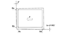
図5は、直角度の悪い転写材に画像を転写した結果の一例を示す図である。同図中、搬送方向が矢印F方向であり、向かって下側の辺が斜行補正の基準辺、つまり突き当て基準部材に突き当てられる辺であるとする。このとき、図示例のような先端辺が基準辺に対して角度α°(>90°)をなす転写材では、幅方向における図の上側と下側での先端余白が不均一となる。特に、上記従来の画像形成装置のような突き当て基準部材の傾き調整が直角度の良い転写材で行われている場合には、断裁精度の良し悪しが全て先端余白の幅方向における不均一に現れるため、却って画像品質の不良として目立ってしまう。 FIG. 5 is a diagram illustrating an example of a result of transferring an image to a transfer material having a bad perpendicularity. In the figure, it is assumed that the transport direction is the arrow F direction, and the lower side is the reference side for skew correction, that is, the side that is abutted against the abutting reference member. At this time, in the transfer material in which the tip side is at an angle α ° (> 90 °) with respect to the reference side as in the illustrated example, the tip margins on the upper side and the lower side in the width direction are not uniform. In particular, when the adjustment of the inclination of the abutting reference member is performed with a transfer material having a good squareness as in the conventional image forming apparatus, all the cutting accuracy is not uniform in the width direction of the leading edge margin. Since it appears, it is conspicuous as a poor image quality.
また、転写材の直角度の問題は、転写材それぞれの個体バラツキが大きいため、一旦突き当て基準部材の角度調整を実施しても十分に解消できないことがある。仮に、転写材の種類や画像形成装置の使用環境(温度や湿度)が変わる度に突き当て基準部材の角度調整を実施するとしても、上記従来の画像形成装置では最適な角度を決定するまでにテストプリントによるトライアンドエラーを繰り返す必要がある。したがって、手間と場合によっては勘を要する作業となってしまう。さらに、転写材の両面にプリントを行う場合においては、トライアンドエラーの作業でさえ実質的には困難を極めることになる。 In addition, the problem of the perpendicularity of the transfer material may not be sufficiently solved even if the angle of the abutting reference member is once adjusted because the individual variations of the transfer material are large. Even if the angle adjustment of the abutting reference member is performed every time the type of transfer material or the use environment (temperature and humidity) of the image forming apparatus changes, until the optimum angle is determined in the conventional image forming apparatus described above. It is necessary to repeat trial and error by the test print. Therefore, it becomes a work which requires time and effort depending on circumstances. Furthermore, when printing on both sides of the transfer material, even the trial and error operation is substantially difficult.
本発明は、この点に着目してなされたものであり、転写材の直角度の良し悪しが非基準辺の余白の不均一に集中しないようにすることが可能となる画像形成装置を提供することを目的とする。 The present invention has been made paying attention to this point, and provides an image forming apparatus capable of preventing the right and wrong of the transfer material from being unevenly concentrated on the non-reference side margins. For the purpose.
また、転写材の断裁精度のバラツキの影響を両面プリント時も含めて考慮したレジストレーション制御を実現することが可能となる画像形成装置を提供することを目的とする。 It is another object of the present invention to provide an image forming apparatus capable of realizing registration control that takes into consideration the influence of variations in the cutting accuracy of a transfer material, including during double-sided printing.
上記目的を達成するため、請求項1に記載の画像形成装置は、搬送されてきた四角形状の転写材に画像をプリントするプリント手段と、前記転写材のある一辺を基準辺とし、少なくとも該基準辺と該基準辺に隣接する他の一辺である非基準辺を検知する検知手段と、前記検知手段によって検知された前記基準辺と前記非基準辺のなす角度α°を算出する第1の算出手段と、|90°−α°|≠0の場合に発生が想定される、前記非基準辺を一辺とする四角形状の画像余白の形状を補正するために、前記基準辺を回転させる角度であって、0<β°<|90°−α°|を満たす角度β°を算出する第2の算出手段と、前記基準辺が前記第2の算出手段によって算出された角度β°だけ、前記画像余白の形状がより方形状に近づく方向に回転するように、前記転写材の斜行補正を行う補正手段とを備えたことを特徴とする。
In order to achieve the above object, an image forming apparatus according to
本発明によれば、少なくとも転写材の基準辺および非基準辺の二辺を検知するようにしたので、転写材が搬送中に斜行していたとしても、その基準辺と非基準辺のなす角度α°を算出することができる。さらに、前記基準辺を回転させる角度であって、0<β°<|90°−α°|を満たす角度β°を算出し、前記基準辺が前記角度β°だけ画像余白の形状がより方形状に近づく方向に回転するように、前記転写材の斜行補正を行うようにしたので、転写材の断裁精度、具体的には直角度が悪い場合でも、斜行補正の非基準辺に発生する画像余白の不均一を目立ち難くすることができる。 According to the present invention, at least two sides of the transfer material, the reference side and the non-reference side, are detected, so even if the transfer material is skewed during conveyance, the reference side and the non-reference side are formed. The angle α ° can be calculated. Further, an angle β ° that is an angle for rotating the reference side and satisfies 0 <β ° <| 90 ° −α ° | is calculated, and the shape of the image margin is more the same for the reference side by the angle β °. Since the skew correction of the transfer material is performed so that it rotates in the direction approaching the shape, even if the cutting accuracy of the transfer material, specifically, the perpendicularity is bad, it occurs on the non-reference side of the skew correction It is possible to make the non-uniformity of the image margin to be conspicuous.
また、斜行補正を行うかどうかを選択できるようにすれば、前記画像余白の不均一が致命的な品質不良となる印刷物に対してのみ、選択的に斜行補正の効果を得ることが可能となる。 In addition, if it is possible to select whether or not to perform skew correction, it is possible to selectively obtain the effect of skew correction only for printed matter in which the non-uniformity of the image margin causes a fatal quality defect. It becomes.
以下、本発明の実施の形態を図面に基づいて詳細に説明する。 Hereinafter, embodiments of the present invention will be described in detail with reference to the drawings.
(第1の実施の形態)
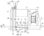
図1は、本発明の第1の実施の形態に係る画像形成装置の内部構造の概略を示す図である。本実施の形態では、電子写真方式のカラー画像形成装置を採用している。同図において、画像形成装置60は、4色の画像形成部を中間転写ベルト上に並べて配置した、所謂中間転写タンデム方式の画像形成装置である。
(First embodiment)
FIG. 1 is a diagram showing an outline of the internal structure of the image forming apparatus according to the first embodiment of the present invention. In this embodiment, an electrophotographic color image forming apparatus is employed. In the figure, an
<転写材の搬送プロセス>
図1において、転写材Sは、転写材収納庫61内の底板62上に積載されて収納されており、給紙部63により画像形成タイミングに合わせて給紙される。なお転写材Sは、四角形状の所定サイズ(例えば、A4判)のコピー用紙である。また給紙部63としては、給紙ローラ等による摩擦分離を利用する方式と、エアによる分離吸着を利用する方式のいずれも採ることができる。本実施の形態では、このうち後者を用いるものとする。
<Transfer material transfer process>
In FIG. 1, the transfer material S is stacked and stored on the
給紙部63により送り出された転写材Sは、搬送ユニット64が有する搬送パス64aを通過し、レジストレーション装置65へと搬送される。転写材Sは、レジストレーション装置65により斜行補正やタイミング補正が施された後、二次転写部へと送られる。二次転写部は、対向する二次転写内ローラ603および二次転写外ローラ66により構成される、転写材Sへのトナー像転写ニップ部であり、所定の加圧力と静電的負荷バイアスを与えることで転写材S上にトナー像を吸着させる。
The transfer material S sent out by the
<画像の作像プロセス>
画像形成部613は、主に感光体608、露光装置611、現像装置610、一次転写装置607および感光体クリーナ609等から構成される。予め帯電装置により表面を一様に帯電され、図中矢印mの方向に回転する感光体608に対し、画像情報に基づいて露光装置611が駆動され、反射ミラー612等を適宜経由して潜像が形成される。感光体608上に形成された静電潜像は、現像装置610によるトナー現像を経て、感光体608上にトナー像として顕在化する。その後、一次転写装置607により静電的負荷バイアスが与えられ、中間転写ベルト606上にトナー像が転写される。その後、感光体608上に転写されずに残った転写残トナーは感光体クリーナ609により回収される。
<Image creation process>
The
なお画像形成部613は、図示例の場合、イエロー(Y)、マゼンタ(M)、シアン(C)およびブラック(Bk)の4セット存在する。
In the illustrated example, the
中間転写ベルト606は、駆動ローラ604、テンションローラ605および二次転写内ローラ603等のローラによって張架され、図中矢印nの方向へと回転駆動される。Y,M,CおよびBkの各画像形成部613により中間転写ベルト606上にトナー画像が重ねて転写され、フルカラーのトナー像が形成され、二次転写部へと搬送される。
The intermediate transfer belt 606 is stretched by rollers such as a driving
<二次転写以降のプロセス>
二次転写部で転写材S上にフルカラーのトナー像が転写され、その後、転写材Sは定着前搬送部67により定着装置68へと搬送される。定着装置68は、対向するローラもしくはベルト等による所定の加圧力と、一般的にはヒータ等の熱源による加熱効果を加えて転写材S上にトナー像を溶融固着させる。このようにして画像の定着した転写材Sは、分岐搬送装置69により、そのまま排紙トレイ600上に排出されるか、もしくは両面画像形成を要する場合には反転搬送装置601へと搬送される。両面画像形成を要する場合、反転搬送装置601へと送られた転写材Sは、スイッチバック動作によって先端と後端とが入れ替えられ、両面搬送装置602へと搬送される。その後、給紙装置61から搬送されてくる後続ジョブの転写材とのタイミングを合わせて、搬送ユニット64が有する再給紙パス64bから合流し、同様に二次転写部へと送られる。なお裏面(2面目)の画像形成プロセスは、前述した表面(1面目)の画像形成プロセスと同様であるので、その説明は省略する。
<Process after secondary transfer>
A full-color toner image is transferred onto the transfer material S at the secondary transfer portion, and then the transfer material S is transported to the fixing device 68 by the
ここで画像形成装置60は、前述のように、転写材Sを反転するためにスイッチバック方式を用いている。しかし、スイッチバック時には転写材Sの先端と後端が入れ替わるため、本実施の形態では、表と裏とで位置が変わらないサイド辺を斜行補正の基準辺に採ることができる斜送レジストレーション方式を採用している。
Here, as described above, the
<斜送レジストレーション方式>
図2は、レジストレーション装置65を含む搬送部の上視図である。同図において、搬送方向は矢印F方向であり、上流側からレジスト前搬送部、斜送レジスト部およびスライド部に分けられる。図示例では、レジスト前搬送部としてベルト搬送方式を用いている。
<Slope feeding registration method>
FIG. 2 is a top view of the conveyance unit including the
転写材Sは、ベルト駆動ローラ1およびベルト従動ローラ3に張架される搬送ベルト4の上に担持され、ベルト駆動モータ5により矢印F方向に搬送される。転写材Sは、搬送ベルト4の裏側に設けられた吸引ファン6による吸引力で保持される。なおレジスト前搬送部は、一般的な搬送ローラ対を用いた構成でも構わない。しかし本実施の形態では、転写材Sの直角度を検知する手段として二次元に素子を配列したエリアセンサを用い、かつレジスト前搬送部を上方から比較的広域に撮像できる構成とするため、上側の搬送ガイドを不要にできる搬送ベルト方式を用いている。
The transfer material S is carried on a conveying
斜送レジスト部は主に、可動ガイド8、斜送ローラ対9a〜9cおよび突き当て基準部材10が一体になった前側可動ユニットと、固定ガイド11とによって構成される。本実施の形態の画像形成装置60は、作像および搬送の基準を幅方向の中央に定めたセンター基準としている。そして前側可動ユニットは、搬送される転写材Sのサイズに応じた最適な待機位置にスライド駆動モータ60dによって幅方向に移動できる仕組みとなっている。ここで最適な待機位置とは、センター基準で定義される画像(あるいは転写材S)の幅方向の端部位置Psに突き当てしろDを加えた位置を意味する。これは、センター基準で搬送される転写材Sが搬送中に幅方向にばらつくため、転写材Sが突き当て基準部材10の入口側端部に激突することなく確実に沿わせるためのオフセット措置である。したがって、突き当て基準部材10に沿って斜行が補正された転写材Sは、画像位置に対しては幅方向に突き当てしろD分だけずれた状態となっている。さらに、突き当て基準部材10は回動中心Rcに対して付勢部材12の引張り力によるモーメントを向かって時計回り方向に受けており、角度調整カム13のカム面に付勢されることで位置が決められている。なお、角度調整カム13のカム面の位相は、角度調整モータ14によって制御される。
The skew feeding registration portion is mainly configured by a
斜送ローラ対9a〜9cは、突き当て基準部材10へ向けての搬送力を生じるように搬送方向Fに対して所定の角度だけ傾けて配設されている。ここで、斜送ローラ対9a〜9cによる斜送が開始されたときには、上流のレジスト前搬送部が斜送を阻害しないように配慮する必要がある。図2に示すように本実施の形態では、斜送センサ15の検知信号をトリガとして吸引シャッター16を閉じるようにしている。これにより、最上流の斜送ローラ対9aによる斜送が開始されると、吸引ファン6による吸引効果は遮断され、転写材Sの拘束力を低下させることができる。
The pair of
スライド部は主に、搬送ガイド17、レジストローラ7、レジスト駆動モータ18、スライドモータ150、レジスト前センサ19およびレジスト後センサ100によって構成される。レジストローラ7は、幅方向にスライド移動できるように支持および駆動される。そしてレジストローラ7は、幅方向に突き当てしろD分だけオフセットした転写材Sの位置を中間転写ベルト606(図1参照)上の画像位置に合わせるために、スライドモータ150により転写材Sを挟持搬送したまま幅方向にスライド移動する。なお、このスライド移動を行う際には、少なくとも上流の斜送ローラ対9a〜9cのニップを解除する必要があるが、そのニップの解除タイミングはレジスト前センサ19による転写材Sの通過信号をトリガとして制御される。一方、レジスト後センサ100によって得られる転写材Sの通過信号は、下流の二次転写外ローラ66(図1参照)への到達タイミングを調整するトリガとして用いられる。なお、二次転写外ローラ66が転写材Sを搬送し始めると、レジストローラ7はニップを解除するとともに、再び幅方向の待機位置までスライド移動して戻る。
The slide part is mainly composed of a
<直角度の検知部>
前述のように本実施の形態では、レジスト前搬送部において搬送される転写材Sの直角度を検知するための手段を設けている。具体的な検知手段としては、例えばCMOS(complementary metal oxide semiconductor)センサに代表されるようなエリアセンサ50を用いている。エリアセンサ50は、図3に示すように搬送ベルト4の上に担持された転写材Sを上方から撮像できるように配置されている。具体的には、光源41によりレジスト前搬送部を照射し、その反射光を適宜結像レンズ51によりエリアセンサ50の素子上に結像させる。これにより、比較的広範囲(例えば図2における検知領域A1)を撮像し、転写材Sの外形を捉えるようにしている。このようにエリアセンサ50を直角度の検知手段に用いれば、転写材Sの隣接する二辺を同時に検知できるため二辺のなす角度(直角度)を正確かつ容易に割り出すことが可能となる。さらに、1つの検知手段によって、外形を捉えるべき転写材Sの多岐にわたるサイズに対応することが可能となる。また、転写材Sが斜行した状態で搬送されていても問題なく検知できるというメリットもある。
<Squareness detection unit>
As described above, in this embodiment, means for detecting the perpendicularity of the transfer material S conveyed in the pre-registration conveyance unit is provided. As a specific detection means, for example, an
なお検知手段として、図4に示すように一次元に素子を配列したラインセンサを用いることも可能である。この場合、少なくとも基準辺と非基準辺の二辺を並行して検知するために、幅方向に2つのラインセンサ110aおよび110b、搬送方向に2つのラインセンサ111aおよび111bを配置する必要がある。レジスト前搬送部は、一般的な搬送ローラ対112と搬送ガイド113(説明の都合上、図4では上ガイドを省略)で構わない。しかし、幅方向および搬送方向のそれぞれ2つのラインセンサの間隔は最小サイズの転写材に合わせて設定しなければならないため、逆に最大サイズの転写材を検知するときには辺の長さに比してライン間隔が狭く、検知される傾きのS/Nが低下する要因となる。これを回避するには、幅方向および搬送方向ともいずれか1つのラインセンサ(例えば、ラインセンサ110bおよび111b)を移動可能に構成するか、もしくは代表的なサイズの転写材に対応できる分だけラインセンサの数を増やすことになる。この結果、図2および図3で説明したようなエリアセンサ50に近い検知網を構成することになる。
As the detection means, a line sensor in which elements are arranged one-dimensionally as shown in FIG. 4 can be used. In this case, in order to detect at least two sides of the reference side and the non-reference side in parallel, it is necessary to arrange two
<基準辺の目標角度>
検知手段(本実施の形態では、エリアセンサ50)により検知された、基準辺と非基準辺のなす角度α°から補正量β°(角度β°)を算出し、基準辺の目標角度を修正および決定する方法について説明する。本来、図2に示したように斜送レジストレーション方式における突き当て基準部材10は、作像時の基準でもある幅方向基準線Syに対して直角な基準線Sx上に位置する。
<Target angle of reference side>
The correction amount β ° (angle β °) is calculated from the angle α ° between the reference side and the non-reference side detected by the detection means (in this embodiment, the area sensor 50), and the target angle of the reference side is corrected. And the method of determining will be described. Originally, as shown in FIG. 2, the abutting
例えば図5に示すような基準辺に対して先端辺(非基準辺)が角度α°(>90°)をなす転写材が搬送されてきた場合、斜送レジストレーション方式では基準辺側の両端における画像余白の長さBcとBdはほぼ等しくなる。なお、ここで画像余白とは、転写材上の画像が転写されるべき領域と転写材の各辺との間の領域のことを意味する。しかし、非基準辺は幅方向に対して(α−90)°傾くことになる。その分、非基準辺側の両端における画像余白の長さBaとBbには断裁精度の悪さの分の差が生じる。即ち、幅方向における手前側の画像余白の量と奥側の画像余白の量が異なってしまう。このような画像余白の量の差は、例えば大判のポスターのような印刷物の場合には視覚的に目立ってしまうため、品質不良として問題になる。そこで本実施の形態では、このような転写材の断裁精度に起因する画像余白の量の差を一辺に集中させないように分散させている。そして、最も効果的に分散させるための補正量β°を以下のようにして求める。 For example, when a transfer material having a leading edge (non-reference edge) of an angle α ° (> 90 °) with respect to the reference edge as shown in FIG. 5 is conveyed, both ends on the reference edge side are used in the oblique registration method. The image margin lengths Bc and Bd in FIG. Here, the image margin means a region between a region where an image on the transfer material is to be transferred and each side of the transfer material. However, the non-reference side is inclined by (α−90) ° with respect to the width direction. Accordingly, there is a difference between the lengths of the image margins Ba and Bb at both ends on the non-reference side side due to poor cutting accuracy. That is, the amount of the image margin on the near side and the amount of the image margin on the back side in the width direction are different. Such a difference in the amount of image margin is visually conspicuous in the case of a printed material such as a large poster, which causes a problem as poor quality. Therefore, in the present embodiment, the difference in the amount of image margin due to the cutting accuracy of the transfer material is dispersed so as not to be concentrated on one side. Then, the correction amount β ° for the most effective dispersion is obtained as follows.
図5に示すように転写材Sの長辺の長さをL、短辺の長さをWとすると、先端辺で発生する余白量差は、 As shown in FIG. 5, when the length of the long side of the transfer material S is L and the length of the short side is W, the margin amount difference generated at the leading end side is
![]()
![]()
となる。今、図2に示す基準線Sxを回動中心Rcに関して時計回り方向に補正量β°だけ回転させた基準線Sx’を定め、図6に示すように余白量差Ba−Bbのうちの一部を基準辺側の余白量差に振り分けることを考える。このとき、最も視覚的に目立ち難く分散させる方法は、長さの異なる二辺の末端で発生する余白量差を等しくする方法である。つまり、図6において、 It becomes. Now, a reference line Sx ′ obtained by rotating the reference line Sx shown in FIG. 2 by the correction amount β ° in the clockwise direction with respect to the rotation center Rc is determined, and one of the margin amount differences Ba−Bb is shown in FIG. Consider that the part is divided into the margin amount difference on the reference side side. At this time, the most visually conspicuous dispersion method is a method of equalizing the margin amount difference generated at the ends of two sides having different lengths. That is, in FIG.

である。したがって、 It is. Therefore,
を満足するような補正量β°を決定し、これを基準辺の目標角度とする新たな基準線Sx’を定める。なお(1)式は、α>90°の場合について記述した式である。一方、α<90°の場合には、α>90°の場合と同様の考え方によって、 A correction amount β ° that satisfies the above is determined, and a new reference line Sx ′ that defines this as a target angle of the reference side is determined. Note that equation (1) is an equation described for α> 90 °. On the other hand, when α <90 °, the same idea as when α> 90 °,
を満足するような補正量β°を決定し、これを基準辺の目標角度とする新たな基準線Sx’を定めればよい。ここで、回動中心Rcの位置は図2の限りではない。しかし回動中心Rcをレジストローラ7側の端部に設ければ、余白量BbとBcを大きく変動させることなく分散させることができるため望ましいと考えられる。
And a new reference line Sx ′ having the target angle of the reference side as a target angle may be determined. Here, the position of the rotation center Rc is not limited to that shown in FIG. However, it is considered desirable to provide the rotation center Rc at the end portion on the
このように転写材の基準辺と非基準辺とのなす角度α°を検知することで、余白量差を視覚的に最も目立ち難くするような基準線Sx’を決定することが可能となる。また、この角度α°の検知手段としてエリアセンサを用いれば、この角度α°を直接検知できるため、搬送中に角度α°の検知と基準線Sx’の決定とを繰り返しながら転写材Sが有するバラツキ要因の影響を補正することも可能となる。 In this way, by detecting the angle α ° formed between the reference side and the non-reference side of the transfer material, it is possible to determine the reference line Sx ′ that makes the margin amount difference visually inconspicuous. Further, if an area sensor is used as the detecting means for the angle α °, the angle α ° can be directly detected. Therefore, the transfer material S has the detection of the angle α ° and the determination of the reference line Sx ′ during the conveyance. It is also possible to correct the influence of the variation factor.
<制御動作>
図7は、上述した転写材Sの補正方法を実現するために必要なシステム構成を示すブロック図である。同図に示すように、画像形成装置60は、CPU60a、検知部60b、補正目標角度調整部60c、スライド駆動モータ60dおよびメモリ60eを備えている。CPU(演算制御部)60aは、例えばエリアセンサに代表される検知部60bから転写材Sの基準辺および非基準辺を検知する。そして、角度α°および補正量β°とその補正方向などを算出し、補正目標となる基準線Sx’の角度を調整する補正目標角度調整部60cに、補正量β°に相当する制御値の指令を出す。また、CPU60aは必要に応じて、算出された種々の値をメモリ60eに記憶する。
<Control action>
FIG. 7 is a block diagram showing a system configuration necessary to realize the above-described correction method for the transfer material S. As shown in the figure, the
図8は、CPU60aが実行する制御処理の手順を示すフローチャートである。同図に示すように、まずCPU60aは、検知部60bを介して、転写材Sの基準辺および非基準辺を検知する(ステップS1)。次にCPU60aは、検知した二辺からそのなす角度α°を算出し(ステップS2)、α≠90°であるか否かを判別する(ステップS3)。この判別の結果、α≠90°でないとき、つまりα=90°のときには、斜行補正の基準線Sx’を求める必要がないので、CPU60aは本制御処理を終了する。一方、α≠90°のときには、CPU60aは、斜行補正のための基準辺がサイド辺であるか否かを判別する(ステップS4)。レジストレーション装置65が採用している斜送レジストレーション方式はこれに該当するため、CPU60aは、前記(1)式または(2)式に基づいて補正量β°および補正方向を算出する。ここで、補正量β°および補正方向は、ステップS2で算出された角度α°>90°のときに前記(1)式に基づいて算出され(ステップS6)、角度α°<90°のときに、前記(2)式に基づいて算出される(ステップS7)。
FIG. 8 is a flowchart showing a procedure of control processing executed by the
CPU60aは、このようにして算出した補正量β°に相当する角度調整カム13の位相を算出し、角度調整モータ14の駆動パルス数に変換し、角度調整モータ14を駆動するための制御指令を出力する(ステップS11)。これにより、転写材Sの断裁精度(|90°−角度α°|)を反映した基準線Sx’による斜行補正がなされる。
The
斜行補正がなされると、CPU60aは、突き当てしろD分だけスライド駆動モータ60dを一律駆動する(ステップS17)。以上の処理は、ある1枚の転写材の片面にプリントを行う処理であり、片面プリントジョブが指定された場合であれば基本的にこれで終了する(ステップS16→終了)。
When the skew correction is performed, the
一方、両面プリントジョブが指定されている場合には、CPU60aは、ステップS6またはS7で算出された補正方向および補正量β°を基に、その転写材Sが2面目のプリントのために再び戻ってきた際の斜行補正基準線Sx’を算出する。具体的には、両面反転方式(本実施の形態では、スイッチバック反転方式)によらず、ステップS2で算出された基準辺と非基準辺の相対的な傾き関係(すなわち直角度)は1面目と2面目では正負が逆転する。すなわち、ステップS18に示すように、補正量の大きさはそのままで補正方向を逆にした−β°を、2面目プリント時の基準線Sx’を定義する値として算出する。一般にプリントジョブでは転写材毎にID番号が割り当てられ、同じ転写材の1面目と2面目の関係を識別および整合することが可能である。そこで、ステップS18で算出された値もこのID番号に付随する情報としてメモリ60eに記憶される(ステップS19)。こうして、再び2面目のプリントのために戻ってきた際には、CPU60aは、補正値−β°に基づいて角度調整モータ14の駆動制御を行う(ステップS11)。
On the other hand, when the double-sided print job is designated, the
以上のように、本実施の形態によれば、両面プリントジョブの場合も含めてトライアンドエラーの調整作業を行わなくても済み、転写材の断裁精度まで考慮したより精度の高いレジストレーションを容易に行うことができる。 As described above, according to this embodiment, it is not necessary to perform a trial-and-error adjustment operation including a case of a double-sided print job, and it is easy to perform highly accurate registration considering the cutting accuracy of the transfer material. Can be done.
なお図8の制御処理は、あるプリントモード機能の1つとして画像形成装置60に搭載するようにしてもよい。例えば、画像形成装置60の操作画面上に、操作者がこの制御処理をオン/オフ可能なプリントモードを選択できるユーザインターフェースを構築しておく。そして操作者は、余白差が気にならない文字比率の高いプリントを行うときには、この制御処理をオフする一方、写真比率の高いポスターサンプルを13インチ×19インチのようなラージサイズにプリントするときには、この制御処理をオンする。これにより、補正量β°の算出や角度調整モータ14の制御を必要最低限に抑えることができ、CPU60aにかかる演算負荷や電力負荷を低減することができる。
Note that the control process of FIG. 8 may be installed in the
(第2の実施の形態)
次に、本発明の第2の実施の形態に係る画像形成装置について説明する。本実施の形態の画像形成装置の内部構造は、基本的には第1の実施の形態の画像形成装置のそれ、つまり図1に記載のものと同じとする。したがって、作像プロセスおよび転写材の搬送プロセスについての説明は省略する。本実施の形態の画像形成装置では、転写材Sの基準辺を接触させる必要がないためにメディア対応力に優れるアクティブレジストレーション方式のレジストレーション装置を採用している。
(Second Embodiment)
Next, an image forming apparatus according to a second embodiment of the present invention will be described. The internal structure of the image forming apparatus of this embodiment is basically the same as that of the image forming apparatus of the first embodiment, that is, the one shown in FIG. Therefore, descriptions of the image forming process and the transfer material conveyance process are omitted. The image forming apparatus according to the present embodiment employs an active registration type registration apparatus that is excellent in media adaptability because it is not necessary to contact the reference side of the transfer material S.
<アクティブレジストレーション方式>
図9は、本実施の形態のレジストレーション装置を含む搬送部の上視図である。同図において、搬送方向は矢印F方向であり、上流側からレジスト前搬送部、斜行補正部およびスライド部に分けられる。レジスト前搬送部は、第1の実施の形態のレジスト前搬送部と同様にベルト搬送方式を用いているので、その詳細な説明は省略する。
<Active registration method>
FIG. 9 is a top view of the transport unit including the registration apparatus of the present embodiment. In the figure, the conveyance direction is the direction of arrow F, and is divided into a pre-registration conveyance unit, a skew feeding correction unit, and a slide unit from the upstream side. Since the pre-registration conveyance unit uses a belt conveyance method in the same manner as the pre-registration conveyance unit of the first embodiment, detailed description thereof is omitted.
斜行補正部は主に、搬送ガイド20と、斜行補正モータ21aおよび21bと、2組の斜行補正ローラ対22aおよび22bと、先端検知用ラインセンサ23aおよび23bと、サイド検知用ラインセンサ24とによって構成される。各斜行補正ローラ対22aおよび22bはそれぞれ、幅方向の同軸上に配置され、転写材Sをそれぞれ独立した搬送速度で搬送駆動して斜行補正を行う。ここで転写材Sの搬送駆動は、各斜行補正モータ21aおよび21bが各斜行補正ローラ対22aおよび22bをそれぞれ独立に回転駆動することで行われる。先端検知用ラインセンサ23aおよび23bは、搬送方向の基準軸線Sxに平行かつ搬送中心に対して対称に配置されている。サイド検知用ラインセンサ24は、幅方向の基準軸線Syに平行に配置されている。
The skew correction unit mainly includes a
斜行補正部に搬送されてきた転写材Sは、その先端が先端検知用ラインセンサ23aおよび23bの2点で検知され、その斜行量が計測される。CPU(演算制御部)60aは、その斜行量をキャンセルするような回転数差を算出し、この回転数差となるように斜行補正モータ21aおよび21bの駆動を制御する。CPU60aは、例えば先行する側の斜行補正モータの回転数を減じ、先端検知用ラインセンサ23aおよび23bの両方の検知レベルが等しくなるのを目標に駆動制御を行う。こうして斜行補正が行われた転写材Sは、後述するレジストローラ7へと搬送される。このときサイド検知用ラインセンサ24によって転写材Sの幅方向の位置が検知され、転写材Sは中間転写ベルト606(図1参照)上の画像位置に対してどの程度ずれているかが判断される。
The transfer material S that has been conveyed to the skew correction unit is detected at two points by the tip
なお、図9では斜行補正度合を連続的に判断しながら回転数制御ができるように、先端検知用にラインセンサを用いたが、一般的な光学式センサを複数配置する構成でも構わない。また、斜行補正モータは一対としたが、複数対設けて段階的に斜行補正を行う構成でも構わない。なお、斜行補正ローラ対22aおよび22bによる斜行補正が開始された時、上流のレジスト前搬送部が補正動作を阻害しないように配慮する必要がある。このため、先端検知用ラインセンサ23aおよび23bの信号レベルが斜行補正ローラ対22aおよび22bに到達したと判断できるレベルをトリガとして、図2と同様に吸引シャッター16を閉じるようにしている。
In FIG. 9, the line sensor is used for tip detection so that the rotational speed can be controlled while continuously determining the skew correction degree. However, a configuration in which a plurality of general optical sensors are arranged may be used. In addition, although a pair of skew correction motors is provided, a configuration in which a plurality of pairs are provided to perform skew correction in stages may be employed. When skew correction by the skew
スライド部は主に、搬送ガイド17、レジストローラ7、レジスト駆動モータ18、スライドモータ150およびレジスト後センサ100によって構成されている。レジストローラ7は、幅方向にスライド移動できるように支持および駆動される。つまりレジストローラ7は、サイド検知用ラインセンサ24によって検知された幅方向のズレ分だけ、中間転写ベルト606上の画像位置に合わせる方向に転写材Sを挟持搬送したままスライドモータ150によりスライド移動する。なお、このスライド移動を行う際には、少なくとも上流の斜行補正ローラ対22aおよび22bのニップを解除する必要がある。このニップを解除するタイミングは、サイド検知用ラインセンサ24による転写材Sの通過信号をトリガとして制御される。また、レジスト後センサ100による転写材Sの通過信号は、下流の二次転写外ローラ66(図1参照)への到達タイミングを調整するトリガとして用いられる。なお、二次転写外ローラ66が転写材Sを搬送し始めると、レジストローラ7はニップを解除するとともに、再び幅方向の待機位置までスライド移動して戻る。
The slide portion mainly includes a
<直角度の検知部>
本実施の形態においても第1の実施の形態と同様に、レジスト前搬送部で搬送される転写材Sの直角度を検知するため、例えばCMOSセンサに代表されるようなエリアセンサ50を有している。検知領域については、図10に示すように透明な小窓部40を設けて転写材Sのある1つの角部だけを検知するようにしてもよい。この場合には、図示例のようにレジスト前搬送部は一般的な搬送ローラ対112と搬送ガイド113を用いて構成でき、また検知領域が狭いことから光学系を小さく構成できる。ただし、図9のように先端辺を基準辺に採るシステムでは、転写材Sの先端領域を全幅に亘って検知できれば2つの角部のそれぞれの角度を同時に算出することができ、より細かい制御を行うことが可能となる。そこで、ここでは図3のように比較的広域を検知できる構成を採り、例えば図9に示す領域A1を検知するものとする。
<Squareness detection unit>
In the present embodiment, similarly to the first embodiment, in order to detect the perpendicularity of the transfer material S conveyed by the pre-registration conveyance unit, for example, an
また、例えば斜行補正部を含む領域A2まで拡大して検知可能な配置構成とすれば、先端検知用ラインセンサ23aおよび23bとサイド検知用ラインセンサ24の機能をエリアセンサ50にて代替できる。つまりこの構成では、これらのラインセンサ23a,23bおよび24を不要にすることができる。特にCMOSセンサのように、ブロック毎の読み出しが可能なエリアセンサを用いれば、検知領域A2を直角度検知ブロック、斜行検知ブロック、サイド位置検知ブロックのように分割し、かつそれぞれを目的に応じた必要分解能で検知することができる。
Further, for example, if the arrangement configuration can be detected by enlarging the region A2 including the skew correction portion, the functions of the tip
<基準辺の目標角度>
検知手段(本実施の形態では、エリアセンサ50)により検知された、基準辺と非基準辺のなす角度α°から補正量β°を算出し、基準辺の目標角度を修正および決定する方法について説明する。本来、図9に示したようにアクティブレジストレーション方式における先端検知用ラインセンサ23aおよび23bの検知信号差は、幅方向基準線Syと転写材Sの先端辺(基準辺)が平行になる状態を“0”としている。
<Target angle of reference side>
A method of correcting and determining the target angle of the reference side by calculating the correction amount β ° from the angle α ° formed by the reference side and the non-reference side detected by the detection means (in this embodiment, the area sensor 50). explain. Originally, as shown in FIG. 9, the detection signal difference between the tip
例えば図11に示すような基準辺に対してサイド辺(非基準辺)が角度α°(>90°)をなす転写材が搬送されてきた場合、アクティブレジストレーション方式では基準辺側の両端の画像余白の長さBaとBbはほぼ等しくなる。しかし、搬送方向に対する非基準辺は(α−90)°傾くことになる。その分、非基準辺側の両端の画像余白の長さBcとBdには断裁精度の悪さの分の差が生じる。これにより視覚的に画像余白の不均一が目立ってしまう。そこで本実施の形態では、このような転写材の断裁精度に起因する画像余白の不均一を一辺に集中させないように分散させている。そして、最も効果的に分散させるための補正量β°を以下のようにして求める。 For example, when a transfer material in which a side side (non-reference side) forms an angle α ° (> 90 °) with respect to a reference side as shown in FIG. Image margin lengths Ba and Bb are substantially equal. However, the non-reference side with respect to the transport direction is inclined by (α−90) °. Accordingly, there is a difference between the image margin lengths Bc and Bd at both ends on the non-reference side side due to poor cutting accuracy. As a result, the non-uniformity of the image margin is noticeable visually. Therefore, in this embodiment, the non-uniformity of the image margin due to the cutting accuracy of the transfer material is dispersed so as not to be concentrated on one side. Then, the correction amount β ° for the most effective dispersion is obtained as follows.
図11に示すように転写材Sの長辺の長さをL、短辺の長さをWとすると、先端辺の両端部で発生する余白量の差は、 As shown in FIG. 11, when the length of the long side of the transfer material S is L and the length of the short side is W, the difference in the amount of blank space generated at both ends of the front end side is
![]()
![]()
となる。上式からも分かるが、本実施の形態のように先端辺を基準辺とするレジストレーション装置の方が、非基準辺の最大長さが長くなるため、同じ角度で断裁された転写材でも非基準辺側に発生する余白量差は大きくなってしまう。 It becomes. As can be seen from the above formula, the registration device with the tip side as the reference side as in the present embodiment has a longer maximum non-reference side length, so even a transfer material cut at the same angle is not. The margin amount difference generated on the reference side becomes large.
今、図9に示す基準線Syを反時計回り方向に補正量β°だけ回転させた基準線Sy’を定め、図12に示すように余白量差Bd−Bcのうちの一部を基準辺側の余白量差に振り分けることを考える。このとき、最も視覚的に目立ち難く分散させる方法は、長さの異なる二辺の末端で発生する余白量差を等しくする方法である。つまり、図12において、 Now, a reference line Sy ′ obtained by rotating the reference line Sy shown in FIG. 9 in the counterclockwise direction by the correction amount β ° is defined, and a part of the margin amount difference Bd−Bc as shown in FIG. Consider distributing the difference in the margin amount on the side. At this time, the most visually conspicuous dispersion method is a method of equalizing the margin amount difference generated at the ends of two sides having different lengths. That is, in FIG.
である。したがって、 It is. Therefore,
を満足するような補正量β°を決定し、これを基準辺の目標角度とする新たな基準線Sy’を定める。なお(3)式は、α>90°の場合について記述した式である。一方、α<90°の場合には、α>90°の場合と同様の考え方によって、 A correction amount β ° that satisfies the above is determined, and a new reference line Sy ′ having the target angle of the reference side as a target angle is determined. Equation (3) is an equation described for α> 90 °. On the other hand, when α <90 °, the same idea as when α> 90 °,
を満足するような補正量β°を決定し、これを基準辺の目標角度とする新たな基準線Sy’を定めればよい。 A correction amount β ° that satisfies the above is determined, and a new reference line Sy ′ having the target angle of the reference side as a target angle may be determined.
このように転写材の基準辺と非基準辺とのなす角度α°を検知することで、余白量差が視覚的に最も目立ち難くするような基準線Sy’を決定することが可能となる。また、この角度α°の検知手段としてエリアセンサを用いれば、この角度α°を直接検知できるため、搬送中に角度α°の検知と基準線Sy’の決定とを繰り返しながら転写材Sが有するバラツキ要因の影響を補正することも可能となる。 In this way, by detecting the angle α ° formed between the reference side and the non-reference side of the transfer material, it is possible to determine the reference line Sy ′ that makes the margin amount difference most visually inconspicuous. Further, if an area sensor is used as the detecting means for the angle α °, the angle α ° can be directly detected. Therefore, the transfer material S has the detection of the angle α ° and the determination of the reference line Sy ′ during the conveyance. It is also possible to correct the influence of the variation factor.
なお、本実施の形態では前述のように、検知領域A1あるいはA2を検知することで、転写剤の2つの角部の角度を同時に検知することができる。前記(3)式または(4)式に代入する角度α°として、これら2つの角度のうち直角度の悪い方を用いることで、より効果的に余白量差を分散させる補正量β°を求めることができる。 In the present embodiment, as described above, by detecting the detection region A1 or A2, the angles of the two corners of the transfer agent can be detected simultaneously. As the angle α ° that is substituted into the equation (3) or (4), the correction angle β ° that more effectively disperses the margin amount difference is obtained by using the one of the two angles having the lesser squareness. be able to.
<制御動作>
以下、図7のシステムおよび図8のフローチャートを用いて、画像形成装置60、特にCPU60aが実行する制御処理を説明する。
<Control action>
Hereinafter, control processing executed by the
CPU60aは、例えばエリアセンサに代表される検知部60bから転写材Sの基準辺および非基準辺を検知する。そして、角度α°および補正量β°とその補正方向などを算出し、この算出値を補正目標となる先端検知用ラインセンサ23aおよび23bの検知信号の所定差に反映させる。つまり、この所定差は初期状態では“0”に設定されているが、補正量β°が算出されると、先端検知用ラインセンサ23aおよび23bの検知信号のタイミングをβ°に相当する分だけずらした状態が斜行補正完了状態となる変更が行われる。また、図9において検知領域を領域A2とした場合には、検知部60bによって転写材Sの幅方向の位置ズレも同時に検知できる。したがって、CPU60aはこの位置ズレ分に相当する駆動パルス数を算出し、その駆動パルス数を含む制御値の指令を、レジストローラ7を幅方向に移動させるスライド駆動モータ60dに出力する。また、CPU60aは必要に応じて、算出された種々の値をメモリ60eに記憶する。
For example, the
図8において、まずCPU60aは、検知部60bを介して、転写材Sの基準辺および非基準辺を検知する(ステップS1)。次にCPU60aは、検知した二辺からそのなす角度α°を算出し(ステップS2)、α≠90°であるか否かを判別する(ステップS3)。この判別の結果、α≠90°でないとき、つまりα=90°のときには、斜行補正の基準線Sy’を求める必要がないので、CPU60aは本制御処理を終了する。一方、α≠90°のときには、CPU60aは、斜行補正のための基準辺がサイド辺であるか否かを判別する(ステップS4)。本実施の形態のレジストレーション装置が採用しているアクティブレジストレーション方式はこれに該当しないため、CPU60aは、前記(3)式または(4)式に基づいて補正量β°および補正方向を算出する。ここで、補正量β°および補正方向は、ステップS2で算出された角度α°>90°のときに前記(3)式に基づいて算出され(ステップS9)、角度α°<90°のときに、前記(4)式に基づいて算出される(ステップS10)。
In FIG. 8, first, the
CPU60aは、このようにして算出した補正量β°に相当する先端検知用ラインセンサ23aおよび23bの検知タイミング差を算出し、斜行補正完了状態を判断する閾値を変更する(ステップS11)。これにより、転写材Sの断裁精度(|直角度−角度α°|)を反映した基準線Sy’による斜行補正がなされる。斜行補正がなされると、CPU60aは、斜送レジストレーション方式を採用しているか否かを判別する(ステップS12)。前述のように、本実施の形態ではアクティブレジストレーション方式を採用しているので、CPU60aは、再び検知部60bを介して、転写材Sの幅方向の位置を検知する(ステップS13)。そしてCPU60aは、検知した幅方向の位置から転写材Sの幅方向の位置ズレを算出し、この幅方向の位置ズレをスライド駆動モータ60dのパルス数に変換する(ステップS14)。さらにCPU60aは、この駆動パルス数を含む制御値の指令をスライド駆動モータ60dに出力する(ステップS15)。以上の処理は、ある1枚の転写材の片面にプリントを行う処理であり、片面プリントジョブが指定された場合であれば基本的にこれで終了する(ステップS16→終了)。
The
一方、両面プリントジョブが指定されている場合には、CPU60aは、ステップS9またはS10で算出された補正方向および補正量β°を基に、その転写材Sが2面目のプリントのために再び戻ってきた際の斜行補正基準線Sy’を算出する。具体的には、両面反転方式(本実施の形態では、スイッチバック反転方式)によらず、ステップS2で算出された基準辺と非基準辺の相対的な傾き関係(すなわち直角度)は1面目と2面目では正負が逆転する。すなわち、ステップS18に示すように、補正量の大きさはそのままで補正方向を逆にした−β°を、2面目プリント時の基準線Sy’を定義する値として算出する。一般にプリントジョブでは転写材毎にID番号が割り当てられ、同じ転写材の1面目と2面目の関係を識別および整合することが可能である。そこで、ステップS18で算出された値もこのID番号に付随する情報としてメモリ60eに記憶される(ステップS19)。こうして、再び2面目のプリントのために戻ってきた際には、CPU60aは、補正値−β°に基づいて先端検知用ラインセンサ23aおよび23bの検知タイミング差の変更を行う(ステップS11)。
On the other hand, when the double-sided print job is designated, the
なお本実施の形態では、先端辺を基準辺とするアクティブレジストレーション方式を例に挙げて説明したが、アクティブレジストレーション方式では、転写材の斜行を検知する辺をサイド辺にすれば、サイド辺を基準辺とする方式も容易に採ることができる。その場合には、スイッチバック反転方式と併せて、転写材の表面と裏面とで基準辺が変わらない構成にすることもできる。この構成を採った場合、補正量β°の決定には第1の実施の形態で説明した(1)式または(2)式を適用(ステップS6またはS7を実行)すればよい。あるいは、本実施の形態のように先端辺を基準辺とするならば、両面時の反転方式をいわゆるスパイラル反転方式にすれば、転写材の表面と裏面とで基準辺が変わらないため、理論的にはより望ましいものとすることができる。 In this embodiment, the active registration method using the tip side as a reference side has been described as an example. However, in the active registration method, if the side for detecting the skew of the transfer material is set as a side side, the side A method using the side as a reference side can also be easily adopted. In that case, in addition to the switchback inversion method, a configuration in which the reference side does not change between the front surface and the back surface of the transfer material can be employed. When this configuration is adopted, the equation (1) or (2) described in the first embodiment may be applied to the correction amount β ° (step S6 or S7 is executed). Alternatively, if the leading edge is used as a reference edge as in this embodiment, if the reversal method for both sides is a so-called spiral reversal method, the reference edge does not change between the front and back surfaces of the transfer material. Can be more desirable.
(第3の実施の形態)
次に、本発明の第3の実施の形態に係る画像形成装置について説明する。
(Third embodiment)
Next, an image forming apparatus according to a third embodiment of the present invention will be described.
本実施の形態の画像形成装置の内部構造は、基本的には第1の実施の形態の画像形成装置のそれ、つまり図1に記載のものと同じとする。したがって、作像プロセスおよび転写材の搬送プロセスについての説明は省略する。本実施の形態の画像形成装置では、最も簡易な構成でコストメリットに優れるシャッターレジストレーション方式のレジストレーション装置を採用している。 The internal structure of the image forming apparatus of this embodiment is basically the same as that of the image forming apparatus of the first embodiment, that is, the one shown in FIG. Therefore, descriptions of the image forming process and the transfer material conveyance process are omitted. The image forming apparatus according to the present embodiment employs a shutter registration type registration apparatus that has the simplest configuration and is excellent in cost merit.
<シャッターレジストレーション方式>
図13は、本実施の形態のレジストレーション装置を含む搬送部の上視図である。同図において、搬送方向は矢印F方向であり、上流側からレジスト前搬送部、斜行補正部およびレジストローラ部に分けられる。レジスト前搬送部は、第1の実施の形態のレジスト前搬送部と同様にベルト搬送方式を用いているので、その詳細な説明は省略する。
<Shutter registration method>
FIG. 13 is a top view of the transport unit including the registration apparatus of the present embodiment. In the figure, the conveyance direction is the direction of arrow F, and is divided into a pre-registration conveyance unit, a skew feeding correction unit, and a registration roller unit from the upstream side. Since the pre-registration conveyance unit uses a belt conveyance method in the same manner as the pre-registration conveyance unit of the first embodiment, detailed description thereof is omitted.
斜行補正部は主に、搬送ガイド30と、シャッター前センサ31と、シャッター部材32と、これを開閉駆動するシャッターモータ33とによって構成される。なお、シャッター部材32の開閉動作の制御は、シャッターモータ33の軸上に設けた不図示の偏芯カムの位相制御などによって行われる。また、シャッター部材32の開閉駆動に用いるアクチュエータは、モータだけでなく、ソレノイドなどを用いても構わない。
The skew correction unit mainly includes a
斜行補正部に搬送されてきた転写材Sは、その先端がシャッター前センサ31によって検知され、所定のタイミングでシャッターモータ33が駆動されて、シャッター部材32が搬送路を塞ぐようにして閉じられる。その結果、転写材Sの先端辺はシャッター部材32に接触し、上流の搬送ベルト4によって押し込まれることになる。しかし、シャッター部材32の上流付近は吸引ファン6の吸引効果が及ばない領域であるため、押し込まれた分を撓ませて吸収するループ空間Gとなっている。したがって、斜行して搬送されてきた転写材Sであっても、先端辺がシャッター部材32に平行になるように押し込まれることになる。こうして斜行が補正された転写材Sは、再びシャッターモータ33が駆動されてシャッター部材32が開くことで、下流のレジストローラ部へと搬送される。なお、上記斜行補正部はユニット化されており、図13に示す搬送部の中でユニットのアライメントが変化できるように支持されている。具体的には、ユニットを支持するユニットステージ34には付勢部材35によって回動中心Rcに関して時計回り方向にモーメントが作用しており、該モーメントを角度調整カム36のカム面で受けることで位置が決められる。さらに、該角度調整カム36のカム面の位相は、角度調整モータ37によって任意に変化させることが可能である。
The front end of the transfer material S conveyed to the skew correction unit is detected by the
レジストローラ部は主に、搬送ガイド17、レジストローラ7、レジスト駆動モータ18、レジスト前センサ19およびレジスト後センサ100によって構成される。レジスト後センサ100による転写材Sの通過信号は、下流の二次転写外ローラ66(図1参照)への到達タイミングを調整するトリガとして用いられる。そして、適宜レジスト駆動モータ18の回転数を制御して中間転写ベルト606(図1参照)上の画像と転写材のタイミングを一致させる。なお、第1および第2の実施の形態で説明したように、レジストローラ7を幅方向にスライド可能な構成として、さらに高精度な画像位置合わせを行うようにしてもよい。
The registration roller portion is mainly composed of a
<直角度の検知部>
本実施の形態においても第1または第2の実施の形態と同様に、レジスト前搬送部で搬送される転写材Sの直角度を検知するため、例えばCMOSセンサに代表されるようなエリアセンサ50を有している。シャッターレジストレーション方式が転写材Sの先端辺を基準辺に採るシステムであるため、第2の実施の形態で説明したように、転写材Sの2つの角部のそれぞれの角度を同時に検知できる図3のような構成を用いる。そして検知領域としては、図9に示す領域A1を検知するものとする。
<Squareness detection unit>
Also in the present embodiment, as in the first or second embodiment, an
<基準辺の目標角度>
本来、図13に示したようにシャッターレジストレーション方式におけるシャッター部材32は、その突き当て面が基準線Syと平行である状態を初期状態とする。したがって、補正量β°に関する考え方は第2の実施の形態におけるそれと同様である。このため、前記(3)式または(4)式に基づいて算出した補正量β°から、転写材の断裁精度に起因する画像余白の不均一を最も効果的に分散させる基準線Sy’を決定する。
<Target angle of reference side>
Originally, as shown in FIG. 13, the
<制御動作>
以下、図7のシステムおよび図8のフローチャートを用いて、画像形成装置60、特にCPU60aが実行する制御処理を説明する。CPU60aは、例えばエリアセンサに代表される検知部60bから転写材Sの基準辺および非基準辺を検知する。そして、角度α°および補正量β°とその補正方向などを算出し、補正目標となる基準線の角度を調整する補正目標角度調整部60cに、補正量β°に相当する制御値の指令を出す。また、CPU60aは必要に応じて、算出された種々の値をメモリ60eに記憶する。
<Control action>
Hereinafter, control processing executed by the
シャッターレジストレーション方式では、基準辺がサイド辺ではないため、図8のステップS4以降は第2の実施の形態と同じ処理を辿る。ただし、ステップS11における制御指令値は、角度調整モータ37の駆動パルス数であり、補正量β°を角度調整カム36の位相に変換することで求められた値となる。
In the shutter registration method, since the reference side is not the side side, the same processing as in the second embodiment is followed from step S4 in FIG. However, the control command value in step S11 is the number of drive pulses of the
以上のように、シャッターレジストレーション方式でも同様に、転写材の断裁精度に起因する画像余白の不均一を、視覚的に最も目立たないように分散させることができる。 As described above, even in the shutter registration method, the non-uniformity of the image margin due to the cutting accuracy of the transfer material can be dispersed so as to be visually inconspicuous.
7・・・レジストローラ
8・・・可動ガイド
9・・・斜送ローラ対
10・・・突き当て基準部材
21・・・斜行補正モータ
22・・・斜行補正ローラ対
23・・・先端検知用ラインセンサ
24・・・サイド検知用ラインセンサ
32・・・シャッター部材
50・・・エリアセンサ
65・・・レジストレーション装置
613・・・画像形成部
S・・・転写材
Sx・・・搬送方向基準線
Sy・・・幅方向基準線
7: Registration roller 8: Movable guide 9: Skew feed roller pair 10: Abutting reference member 21 ... Skew correction motor 22 ... Skew correction roller pair 23 ... Tip
Claims (11)
前記転写材のある一辺を基準辺とし、少なくとも該基準辺と該基準辺に隣接する他の一辺である非基準辺を検知する検知手段と、
前記検知手段によって検知された前記基準辺と前記非基準辺のなす角度α°を算出する第1の算出手段と、
|90°−α°|≠0の場合に発生が想定される、前記非基準辺を一辺とする四角形状の画像余白の形状を補正するために、前記基準辺を回転させる角度であって、0<β°<|90°−α°|を満たす角度β°を算出する第2の算出手段と、
前記基準辺が前記第2の算出手段によって算出された角度β°だけ、前記画像余白の形状がより方形状に近づく方向に回転するように、前記転写材の斜行補正を行う補正手段と
を備えたことを特徴とする画像形成装置。 Printing means for printing an image on a rectangular transfer material that has been conveyed;
A detection means for detecting a non-reference side that is at least one side adjacent to the reference side and the reference side, with one side of the transfer material as a reference side;
First calculation means for calculating an angle α ° between the reference side detected by the detection means and the non-reference side;
An angle at which the reference side is rotated in order to correct the shape of a rectangular image margin having the non-reference side as one side, which is assumed to occur when | 90 ° −α ° | ≠ 0, Second calculating means for calculating an angle β ° satisfying 0 <β ° <| 90 ° −α ° |
Correction means for correcting the skew of the transfer material so that the reference margin rotates in the direction closer to the square by the angle β ° calculated by the second calculation means. An image forming apparatus comprising the image forming apparatus.
前記第1の算出手段は、前記検知された基準辺と二辺の非基準辺のなす2つの角度を算出し、該算出した2つの角度のうち直角度の悪い方の値を前記角度α°とすることを特徴とする請求項1または2に記載の画像形成装置。 The detecting means detects another non-reference side adjacent to the reference side;
The first calculating means calculates two angles formed by the detected reference side and two non-reference sides, and calculates a value of the calculated two angles that is less perpendicular to the angle α °. The image forming apparatus according to claim 1, wherein the image forming apparatus is an image forming apparatus.
前記第2の算出手段は、前記転写材の両面に画像をプリントするジョブが選択された場合には、前記転写材の表面について算出した前記角度β°を当該転写材の裏面については−β°として算出することを特徴とする請求項1〜3のいずれかに記載の画像形成装置。 The printing means is capable of printing images on both sides of the transfer material,
When a job for printing an image on both sides of the transfer material is selected, the second calculation means calculates the angle β ° calculated for the front surface of the transfer material as −β ° for the back surface of the transfer material. The image forming apparatus according to claim 1, wherein the image forming apparatus is calculated as follows.
前記第2の算出手段は、前記転写材の長辺の長さをLとし、短辺の長さをWとした場合に、前記角度β°を
The second calculation means calculates the angle β ° when the length of the long side of the transfer material is L and the length of the short side is W.
前記第2の算出手段は、前記転写材の長辺の長さをLとし、短辺の長さをWとした場合に、前記角度β°を
The second calculation means calculates the angle β ° when the length of the long side of the transfer material is L and the length of the short side is W.
Priority Applications (1)
| Application Number | Priority Date | Filing Date | Title |
|---|---|---|---|
| JP2009253016A JP5404323B2 (en) | 2009-11-04 | 2009-11-04 | Image forming apparatus |
Applications Claiming Priority (1)
| Application Number | Priority Date | Filing Date | Title |
|---|---|---|---|
| JP2009253016A JP5404323B2 (en) | 2009-11-04 | 2009-11-04 | Image forming apparatus |
Publications (2)
| Publication Number | Publication Date |
|---|---|
| JP2011098790A JP2011098790A (en) | 2011-05-19 |
| JP5404323B2 true JP5404323B2 (en) | 2014-01-29 |
Family
ID=44190308
Family Applications (1)
| Application Number | Title | Priority Date | Filing Date |
|---|---|---|---|
| JP2009253016A Expired - Fee Related JP5404323B2 (en) | 2009-11-04 | 2009-11-04 | Image forming apparatus |
Country Status (1)
| Country | Link |
|---|---|
| JP (1) | JP5404323B2 (en) |
Families Citing this family (23)
| Publication number | Priority date | Publication date | Assignee | Title |
|---|---|---|---|---|
| JP5895555B2 (en) * | 2012-01-25 | 2016-03-30 | コニカミノルタ株式会社 | Image forming apparatus |
| US9776819B2 (en) | 2014-12-09 | 2017-10-03 | Ricoh Company, Ltd. | Sheet conveying device and image forming apparatus incorporating the sheet conveying device |
| US11066263B2 (en) | 2014-12-09 | 2021-07-20 | Ricoh Company, Ltd. | Sheet conveying device and image forming apparatus incorporating the sheet conveying device |
| JP6561820B2 (en) * | 2015-12-16 | 2019-08-21 | コニカミノルタ株式会社 | Image forming apparatus |
| JP6705273B2 (en) * | 2016-04-21 | 2020-06-03 | コニカミノルタ株式会社 | Image forming device |
| US11445082B2 (en) | 2016-11-30 | 2022-09-13 | Ricoh Company, Ltd. | Image forming apparatus incorporating position detector and position corrector |
| US10392213B2 (en) | 2016-12-08 | 2019-08-27 | Ricoh Company, Ltd. | Sheet conveying device and image forming apparatus incorporating the sheet conveying device |
| JP2018095478A (en) | 2016-12-08 | 2018-06-21 | 株式会社リコー | Sheet-like body conveyance device and image formation apparatus |
| EP3348504B1 (en) | 2017-01-11 | 2021-02-03 | Ricoh Company, Ltd. | Sheet conveying device and image forming apparatus incorporating the sheet conveying device |
| US10530950B2 (en) | 2017-02-22 | 2020-01-07 | Ricoh Company, Ltd. | Sheet conveying device, image forming apparatus incorporating the sheet conveying device, and post processing device incorporating the sheet conveying device |
| US10106354B2 (en) | 2017-03-02 | 2018-10-23 | Ricoh Company, Ltd. | Sheet conveying device, image forming apparatus incorporating the sheet conveying device, and post processing device incorporating the sheet conveying device |
| JP7011792B2 (en) | 2017-03-21 | 2022-01-27 | 株式会社リコー | Transport equipment, image forming equipment and post-processing equipment |
| US10358309B2 (en) | 2017-03-21 | 2019-07-23 | Ricoh Company, Ltd. | Sheet conveying device, image forming apparatus incorporating the sheet conveying device, and post processing device incorporating the sheet conveying device |
| EP3412610B1 (en) | 2017-06-06 | 2023-03-01 | Ricoh Company, Ltd. | Sheet conveying device and image forming apparatus incorporating the sheet conveying device |
| EP3415451B1 (en) | 2017-06-15 | 2020-09-16 | Ricoh Company, Ltd. | Sheet conveying device and image forming apparatus incorporating the sheet conveying device |
| EP3492411B1 (en) | 2017-11-29 | 2024-02-14 | Ricoh Company, Ltd. | Sheet conveying device and image forming apparatus incorporating the sheet conveying device |
| US11427423B2 (en) | 2017-11-30 | 2022-08-30 | Ricoh Company, Ltd. | Sheet conveying device and image forming apparatus incorporating the sheet conveying device |
| US11345558B2 (en) | 2017-11-30 | 2022-05-31 | Ricoh Company, Ltd. | Sheet conveying device, image forming apparatus incorporating the sheet conveying device, method of conveying conveyance target medium, and method of forming image on conveyance target medium using the method of forming image |
| JP7004247B2 (en) | 2018-02-08 | 2022-01-21 | 株式会社リコー | Image forming device |
| US11148892B2 (en) | 2018-03-06 | 2021-10-19 | Ricoh Company, Ltd. | Sheet conveying device, image forming apparatus incorporating the sheet conveying device, sheet conveying method using the image forming apparatus incorporating the sheet conveying device, and image forming method using the image forming apparatus incorporating the sheet conveying device |
| JP2019156622A (en) | 2018-03-16 | 2019-09-19 | 株式会社リコー | Device and method for transport, and image forming apparatus |
| JP7132539B2 (en) * | 2018-03-19 | 2022-09-07 | 株式会社リコー | Conveying device, image forming device |
| JP7497627B2 (en) | 2020-07-02 | 2024-06-11 | コニカミノルタ株式会社 | Image forming apparatus and image adjustment method |
Family Cites Families (4)
| Publication number | Priority date | Publication date | Assignee | Title |
|---|---|---|---|---|
| JPH1087118A (en) * | 1996-09-17 | 1998-04-07 | Ricoh Co Ltd | Image forming device |
| JP4385627B2 (en) * | 2003-03-24 | 2009-12-16 | 富士ゼロックス株式会社 | Sheet conveying apparatus and sheet processing apparatus using the same |
| JP4367429B2 (en) * | 2006-04-14 | 2009-11-18 | コニカミノルタビジネステクノロジーズ株式会社 | Image forming apparatus |
| JP2009085666A (en) * | 2007-09-28 | 2009-04-23 | Fujifilm Corp | Sheet inclination angle measuring method, sheet inspection method, and sheet inspection apparatus |
-
2009
- 2009-11-04 JP JP2009253016A patent/JP5404323B2/en not_active Expired - Fee Related
Also Published As
| Publication number | Publication date |
|---|---|
| JP2011098790A (en) | 2011-05-19 |
Similar Documents
| Publication | Publication Date | Title |
|---|---|---|
| JP5404323B2 (en) | Image forming apparatus | |
| US8459640B2 (en) | Transporting device and image forming apparatus using the same | |
| JP2017090911A (en) | Image forming apparatus and program | |
| JP2018090404A (en) | Conveyance device and image formation apparatus | |
| JP2018095466A (en) | Sheet-like body conveyance device and image formation apparatus | |
| JP5233420B2 (en) | Conveyance control device and image forming apparatus | |
| US9557701B2 (en) | Sheet conveyance apparatus | |
| US8577278B2 (en) | Image forming apparatus to form images on sheets utilizing detected sheet slide positions | |
| US9769327B2 (en) | Image forming apparatus and method of positional adjustment in image formation | |
| US20190317440A1 (en) | Image forming apparatus and image forming control method | |
| JP4376196B2 (en) | Image forming apparatus | |
| US20190129345A1 (en) | Image forming apparatus and conveyance control method | |
| US20220229390A1 (en) | Image forming apparatus | |
| JP7277246B2 (en) | image forming device | |
| JP3882533B2 (en) | Paper conveying apparatus and image forming apparatus | |
| JP4717723B2 (en) | Recording material detector | |
| JP3849464B2 (en) | Paper conveying apparatus and image forming apparatus | |
| JP2022110457A (en) | Sheet conveyance device and image forming device | |
| JP5434175B2 (en) | Image forming apparatus | |
| JP6780409B2 (en) | Image forming device | |
| JPH0388659A (en) | Sheet conveyer | |
| US20230139410A1 (en) | Image forming apparatus | |
| JPH07134022A (en) | Device for detecting paper thickness in image forming device | |
| JP2022044379A (en) | Image forming apparatus | |
| JP2020007092A (en) | Image forming apparatus |
Legal Events
| Date | Code | Title | Description |
|---|---|---|---|
| A621 | Written request for application examination |
Free format text: JAPANESE INTERMEDIATE CODE: A621 Effective date: 20121102 |
|
| A977 | Report on retrieval |
Free format text: JAPANESE INTERMEDIATE CODE: A971007 Effective date: 20130920 |
|
| A01 | Written decision to grant a patent or to grant a registration (utility model) |
Free format text: JAPANESE INTERMEDIATE CODE: A01 Effective date: 20131001 |
|
| A61 | First payment of annual fees (during grant procedure) |
Free format text: JAPANESE INTERMEDIATE CODE: A61 Effective date: 20131029 |
|
| LAPS | Cancellation because of no payment of annual fees |