US6603980B1 - Transmitter-receiver, and method for controlling transmission power of the same - Google Patents
Transmitter-receiver, and method for controlling transmission power of the same Download PDFInfo
- Publication number
- US6603980B1 US6603980B1 US09/529,871 US52987100A US6603980B1 US 6603980 B1 US6603980 B1 US 6603980B1 US 52987100 A US52987100 A US 52987100A US 6603980 B1 US6603980 B1 US 6603980B1
- Authority
- US
- United States
- Prior art keywords
- transmit power
- amplitude
- power control
- transmission
- bit
- Prior art date
- Legal status (The legal status is an assumption and is not a legal conclusion. Google has not performed a legal analysis and makes no representation as to the accuracy of the status listed.)
- Expired - Lifetime
Links
Images


Classifications
-
- H—ELECTRICITY
- H04—ELECTRIC COMMUNICATION TECHNIQUE
- H04W—WIRELESS COMMUNICATION NETWORKS
- H04W52/00—Power management, e.g. TPC [Transmission Power Control], power saving or power classes
- H04W52/04—TPC
- H04W52/18—TPC being performed according to specific parameters
- H04W52/22—TPC being performed according to specific parameters taking into account previous information or commands
- H04W52/223—TPC being performed according to specific parameters taking into account previous information or commands predicting future states of the transmission
-
- H—ELECTRICITY
- H04—ELECTRIC COMMUNICATION TECHNIQUE
- H04B—TRANSMISSION
- H04B1/00—Details of transmission systems, not covered by a single one of groups H04B3/00 - H04B13/00; Details of transmission systems not characterised by the medium used for transmission
- H04B1/02—Transmitters
- H04B1/04—Circuits
-
- H—ELECTRICITY
- H04—ELECTRIC COMMUNICATION TECHNIQUE
- H04W—WIRELESS COMMUNICATION NETWORKS
- H04W52/00—Power management, e.g. TPC [Transmission Power Control], power saving or power classes
- H04W52/04—TPC
-
- H—ELECTRICITY
- H04—ELECTRIC COMMUNICATION TECHNIQUE
- H04W—WIRELESS COMMUNICATION NETWORKS
- H04W52/00—Power management, e.g. TPC [Transmission Power Control], power saving or power classes
- H04W52/04—TPC
- H04W52/18—TPC being performed according to specific parameters
- H04W52/28—TPC being performed according to specific parameters using user profile, e.g. mobile speed, priority or network state, e.g. standby, idle or non transmission
- H04W52/283—Power depending on the position of the mobile
-
- H—ELECTRICITY
- H04—ELECTRIC COMMUNICATION TECHNIQUE
- H04W—WIRELESS COMMUNICATION NETWORKS
- H04W52/00—Power management, e.g. TPC [Transmission Power Control], power saving or power classes
- H04W52/04—TPC
- H04W52/18—TPC being performed according to specific parameters
- H04W52/28—TPC being performed according to specific parameters using user profile, e.g. mobile speed, priority or network state, e.g. standby, idle or non transmission
- H04W52/288—TPC being performed according to specific parameters using user profile, e.g. mobile speed, priority or network state, e.g. standby, idle or non transmission taking into account the usage mode, e.g. hands-free, data transmission, telephone
-
- H—ELECTRICITY
- H04—ELECTRIC COMMUNICATION TECHNIQUE
- H04W—WIRELESS COMMUNICATION NETWORKS
- H04W52/00—Power management, e.g. TPC [Transmission Power Control], power saving or power classes
- H04W52/04—TPC
- H04W52/54—Signalisation aspects of the TPC commands, e.g. frame structure
-
- H—ELECTRICITY
- H04—ELECTRIC COMMUNICATION TECHNIQUE
- H04W—WIRELESS COMMUNICATION NETWORKS
- H04W52/00—Power management, e.g. TPC [Transmission Power Control], power saving or power classes
- H04W52/04—TPC
- H04W52/18—TPC being performed according to specific parameters
- H04W52/24—TPC being performed according to specific parameters using SIR [Signal to Interference Ratio] or other wireless path parameters
-
- H—ELECTRICITY
- H04—ELECTRIC COMMUNICATION TECHNIQUE
- H04W—WIRELESS COMMUNICATION NETWORKS
- H04W52/00—Power management, e.g. TPC [Transmission Power Control], power saving or power classes
- H04W52/04—TPC
- H04W52/30—TPC using constraints in the total amount of available transmission power
- H04W52/36—TPC using constraints in the total amount of available transmission power with a discrete range or set of values, e.g. step size, ramping or offsets
-
- H—ELECTRICITY
- H04—ELECTRIC COMMUNICATION TECHNIQUE
- H04W—WIRELESS COMMUNICATION NETWORKS
- H04W52/00—Power management, e.g. TPC [Transmission Power Control], power saving or power classes
- H04W52/04—TPC
- H04W52/38—TPC being performed in particular situations
- H04W52/44—TPC being performed in particular situations in connection with interruption of transmission
Definitions
- the present invention relates to a transmission/reception apparatus and its transmit power control method of a mobile communication using a CDMA system.
- FIG. 1 is a main block diagram showing an outlined configuration of a conventional transmission/reception apparatus.
- Frame assembling section 1 multiplexes transmission data with a TPC bit.
- Spreading section 2 spreads/modulates the multiplexed data and BPF 3 eliminates an unnecessary signal from the spread/modulated signal.
- Transmission amplifier 4 amplifies the transmission signal stripped of the unnecessary signal.
- Duplexer 5 controls an input/output signal to/from antenna 6 .
- Antenna 6 radiates the amplified transmission signal.
- Antenna 6 receives a transmitted signal.
- Despreading section 7 demodulates the reception signal.
- received quality detecting section 8 detects a received quality by calculating a signal interference ratio (hereinafter referred to as “SIR”) from the result of despreading performed by despreading section 7 .
- SIR signal interference ratio
- TPC bit generating section 9 receives the detection result of received quality detecting section 8 and generates a TPC bit to instruct a far-end station to increase transmit power if the received quality falls 10 below a desired quality and lower transmit power if the received quality equals to or exceeds the desired quality to reduce interference with other users. For example, the TPC bit is set to 1 if the received quality falls below the desired quality and 0 if the received quality equals to or exceeds the desired quality.
- the TPC bit generated is sent to frame assembling section 1 and multiplexed with transmission data.
- Determining section 10 acquires reception data from the demodulated reception signal and at the same time extracts the TPC bit generated and sent by the far-end station and determines whether the TPC bit is 0 or 1.
- Accumulating section 11 receives the judgment result of determining section 10 and instructs transmission amplifier 4 to increase or decrease transmit power according to the result. It is predetermined that, for example, if the determination result is 0, accumulating section 11 determines that the instruction from the far-end station is to decrease transmit power and decreases the current amount of amplification by 1 dB and if the determination result is 1, accumulating section 11 determines that the instruction from the far-end station is to increase transmit power and increases the current amount of amplification by 1 dB.
- the conventional transmission/reception apparatus and transmit power control method maintain appropriate transmit power by the transmission/reception apparatuses of both the base station and mobile station carrying out transmit power control based on the TPC bit in the reception signal.
- an amount of the increase or decrease during transmit power control that is, a range of transmit power to be increased or decreased based on a TPC bit made up of one received bit is a predetermined fixed value ( ⁇ 1 dB in the example above)
- this fixed value is too large, it is difficult to control transmit power appropriately and maintain stability when amplitude variations are small (during slow fading), whereas if this fixed value is too small, poor traceability results when there are considerable amplitude variations (during fast fading).
- a situation with large amplitude variations occurs, for example, when a compressed mode is used.
- a system which provides a pause interval such as compressed mode produces a large difference between a control transmit power value and required transmit power value which is a target value.
- the example above has a TPC bit made up of one bit, and therefore can only transmit or receive two values, that is, “increase or” decrease. Therefore, it is also possible to increase an amount of information that can be transmitted/received by increasing assignment to the TPC bit within one slot and finely control not only an increase or decrease of transmit power but also the amount of the increase or decrease.
- the number of bits within one slot is fixed, increasing the number of bits used as TPC bits will cause a problem of reducing data transmission efficiency.
- control is limited to increasing or decreasing transmit power even if transmit power is appropriate and it is preferable to maintain the current value, and thus it is not possible to maintain a fixed value, ending up repeating increases and decreases in short cycles centered on an appropriate value.
- the transmission/reception apparatus and its transmit power control method in the present invention allows the amplitude of a TPC bit to be set apart from other transmission signals. Especially, using not only the symbol of a TPC bit but also the amplitude as parameters allows the symbol to represent an increase or decrease and the amplitude to represent an amount of the increase or decrease, making it possible for one TPC bit to transmit not only control of a certain amount of increase or decrease of transmit power but also control by increasing or decreasing transmit power by an arbitrary amount of increase or decrease.
- FIG. 1 is a block diagram showing an outlined configuration of a conventional transmission/reception apparatus
- FIG. 2 is a main block diagram showing an outlined configuration of a transmission/reception apparatus according to Embodiment 1 of the present invention
- FIG. 3 is a main block diagram showing an outlined configuration of a received quality detecting section according to Embodiment 1 of the present invention
- FIG. 4 is a main block diagram showing an outlined configuration of a transmission/reception apparatus with a limiter provided between a multiplying section and transmission amplifier according to Embodiment 2 of the present invention
- FIG. 5 is a main block diagram showing an outlined configuration of the transmission/reception apparatus with a limiter provided between a received quality detecting section and switching section according to Embodiment 2 of the present invention
- FIG. 6 is a main block diagram showing an outlined configuration of the transmission/reception apparatus with a limiter provided between an accumulating section and a multiplying section according to Embodiment 2 of the present invention
- FIG. 7 is a main block diagram showing an outlined configuration of the transmission/reception apparatus with a limiter provided between a determining section and accumulating section according to Embodiment 2 of the present invention
- FIG. 8 is a main block diagram showing an outlined configuration of a transmission/reception apparatus according to Embodiment 3 of the present invention.
- FIG. 9 A and FIG. 9B are transmission timing charts to explain a compressed mode
- FIG. 10 A and FIG. 10B are slot diagrams to explain a compressed mode
- FIG. 11 is are drawings showing variations of a channel quality to explain transmit power control in Embodiment 3 of the present invention.
- FIG. 12 are other drawings showing variations of the channel quality to explain transmit power control in Embodiment 3 of the present invention.
- FIG. 13 is a main block diagram showing an outlined configuration of a transmission/reception apparatus according to Embodiment 4 of the present invention.
- FIG. 14A are graphs showing variations of conventional control transmit power and SIR
- FIG. 14B are graphs showing variations of control transmit power and SIR to explain transmit power control according to Embodiment 4 of the present invention.
- FIG. 15 is a main block diagram showing an outlined configuration of a transmission/reception apparatus according to Embodiment 5 of the present invention.
- FIG. 16 are graphs showing variations of control transmit power and SIR to explain transmit power control according to Embodiment 5 of the present invention.
- FIG. 17 is a main block diagram showing an outlined configuration of a transmission/reception apparatus according to Embodiment 6 of the present invention.
- FIG. 18 are graphs showing variations of control transmit power and SIR to explain transmit power control according to Embodiment 6 of the present invention.
- FIG. 19 is a main block diagram showing an outlined configuration of a transmission/reception apparatus according to Embodiment 7 of the present invention.
- FIG. 20 is a schematic diagram showing a frame format example to explain chip interleaving.
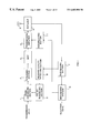
- FIG. 2 is a block diagram showing an outlined configuration of the transmission/reception apparatus according to Embodiment 1 of the present invention.
- Frame assembling section 101 multiplexes transmission data with a TPC bit.
- Spreading section 102 spreads/modulates the multiplexed data.
- BPF 103 eliminates an unnecessary signal.
- Transmission amplifier 104 amplifies the transmission signal. This transmission signal is radiated from antenna 106 via duplexer 105 .
- Antenna 106 receives a transmitted signal.
- Despreading section 107 demodulates the reception signal.
- received quality detecting section 108 detects a received quality from an SIR of despreading section 107 .
- the configuration of received quality detecting section 108 will be described later.
- TPC bit generating section 109 generates a TPC bit based on this received quality and sends it to frame assembling section 101 .
- Determining section 110 includes bit determining section 111 and amplitude reading section 112 . Determining section 110 acquires reception data from the demodulated reception signal and outputs it. Bit determining section 111 extracts a TPC bit from the reception signal and determines whether the TPC bit is 0 or 1. On the other hand, amplitude reading section 112 reads a ratio of the amplitude of the signal other than the TPC bit to the amplitude of the TPC bit in the reception signal.
- Accumulating section 113 obtains the symbol and amplitude ratio of the TPC bit of the reception signal from determining section 110 .
- the symbol indicates an instruction for an increase or instruction for a decrease of transmit power and the amplitude ratio indicates an amount of the increase or decrease of transmit power.
- Accumulating section 113 can obtain an amplitude control value to instruct transmission amplifier 104 to increase or decrease transmit power by an arbitrary amount of increase or decrease by combining these two conditions.
- the amplitude of the TPC bit variable by making the amplitude of the TPC bit variable and using not only the symbol but also the amplitude as parameters, it is possible to perform not only control of a certain amount of increase or decrease of transmit power but also fine control increasing or decreasing transmit power by an arbitrary amount of increase or decrease. Therefore, it is possible to respond not only to fast fading with large amplitude variations but also to slow fading with small amplitude variations.
- the amplitude control value which is the output of accumulating section 113 , is ⁇ 0 and the increase or decrease instruction indicated by the TPC bit symbol is substantially insignificant and an instruction “retain the current value” is sent to transmission amplifier 104 .
- Multiplying section 114 has a function to instruct transmission amplifier 104 to transmit the TPC bit in the transmission signal with a variable amplitude based on the received quality, not the same amplitude as that of other bits based on the amplitude control value calculated by accumulating section 113 . That is, it is possible to include the received quality by multiplying the amplitude control value by a correction value calculated from the received quality detected by received quality detecting section 108 only during transmit power control of the TPC bit.
- This correction value is proportional to a difference between the received quality and desired quality. That is, the farther the received quality is from the received quality, the larger the correction value becomes, and the smaller the distance, the closer to 1 the correction value comes. Thus, it is possible to provide an amplitude proportional to the requested amount of increase or decrease of transmit power control to the far-end station for the TPC bit in the transmission signal. The method of calculating the correction value will be described later.
- Switching section 115 has a function to switch between pre-stored value “1” and a value indicating the received quality from received quality detecting section 108 and send either one to multiplying section 114 .
- This function of switching section 115 makes it possible to always maintain the correction value to 1 when controlling transmit power of bits other than the TPC bit and send the correction value from received quality detecting section 108 to multiplying section 114 only when controlling transmit power of the TPC bit.
- FIG.3 is a main block diagram showing an outlined configuration of the received quality detecting section according to Embodiment 1.
- an SIR is measured by SIR measuring section 201 first.
- Subtracting section 202 subtracts a reference SIR retained by storing section 203 from the SIR of the measured reception signal (hereinafter referred to as “measured SIR”) and sends the result to positive/negative determining section 204 .
- Positive/negative determining section 204 determines whether the subtraction result is positive or negative and sends the result to TPC bit generating section 109 . This allows TPC bit generating section 109 to determine 0 or 1, that is, whether to instruct to increase or decrease transmit power and generate the bit.
- Dividing section 205 calculates the ratio of the measured SIR to the reference SIR and sends the result to amplitude converting section 206 .
- Amplitude converting section 206 converts the division result, which is the input, into a monotonically increasing function so that the input and output have a one-to-one relation and sends the output as an amplitude control correction value to multiplying section 114 via switching section 115 .
- the ratio of the measured SIR to the reference SIR it is possible to measure or calculate the signal to noise ratio and compare it with the pre-stored reference SIR and thus obtain the difference from the reference, thus allowing the received quality of the reception signal to be detected.
- this amplitude converting section 206 As the conversion method carried out by this amplitude converting section 206 , the following method can be used for example:
- Y is defined as follows:
- SQRT(Z) is a function that returns a square root of Z
- ABS(Z) is a function that returns an absolute value of Z.
- Y which is sent to multiplying section 114 , plays a part in correcting the amplitude control value, which is the output of accumulating section 113 , according to the received quality only during control of transmit power of the TPC bit. It is possible to suppress amplitude variations to a small value more than a correction that is directly proportional to errors by using a log and a square root as obtained in the mathematical expression above. That is, when error X is large it is possible to prevent correction value Y from becoming larger than necessary, reducing the load on transmission amplifier 104 .
- the present embodiment makes variable the amplitude of the TPC bit in one slot during transmission, providing an additional parameter of an amplitude value, making it possible to send more information with the same one bit, transmit not only a request to increase or decrease transmit power to the far-end station but also a request of the amount of increase or decrease with the TPC bit made up of one bit, thus improving the trackability during fast fading and stability during slow fading without reducing data transmission efficiency.
- this method can send an instruction to increase or decrease transmit power by means of the symbol of the TPC bit made up of one bit in the reception signal and send an instruction about how much transmit power should be increased or decreased by means of the amplitude of the TPC bit, making it possible to send information of an increase or decrease of transmit power and an amount of the increase or decrease without reducing data transmission efficiency, allowing the far-end station to control transmit power responding to both fast fading and slow fading compared to transmit power control that only increases or decreases transmit power by a fixed value.
- the present embodiment can receive a transmit power control request from the far-end station, change transmit power accordingly and send a transmit power control request to the far-end station calculated from the received quality, thus allowing the communication quality to be maintained in an optimal state.
- the transmission/reception apparatus has the same configuration as that in Embodiment 1, provided, however, with a limiter to prevent the transmission amplifier from being requested to increase transmit power excessively.
- the limiter can be placed 1) between the multiplying section and transmission amplifier, 2) between the received quality detecting section and switching section, 3) between the accumulating section and multiplying section and 4) between the determining section and accumulating section. Cases 1) to 4) will be explained below using FIG. 4 to FIG. 7 .
- the parts with the same configuration as that in Embodiment 1 are assigned the same codes and their detailed explanations are omitted.
- FIG. 4 The configuration of the transmission/reception apparatus when a limiter is placed 1) between the multiplying section and transmission amplifier is shown in FIG. 4 .
- an amplitude control value of transmit power sent from multiplying section 114 to transmission amplifier 104 can be limited by limiter 301 . Therefore, if a communication quality deteriorates because the mobile station is located in a fading valley and a request to increase transmit power excessively is made to transmission amplifier 104 as a consequence, it is possible to limit the amplitude control value by limiter 301 to purposefully allow quality deterioration preventing excessive transmit power.
- FIG. 5 The configuration of the transmission/reception apparatus when a limiter is placed 2) between the received quality detecting section and switching section is shown in FIG. 5 .
- FIG. 5 it is possible to limit the amplitude control correction value to be sent from received quality detecting section 108 to multiplying section 114 via switching section 115 using limiter 401 . Therefore, it is possible to prevent the detection result of received quality detecting section 108 from being disturbed due to noise or interference, prevent a value exceeding the actually necessary correction value from being output to multiplying section 114 and prevent a request for an excessive increase of transmit power.
- FIG. 5 The configuration of the transmission/reception apparatus when a limiter is placed 3) between the accumulating section and multiplying section is shown in FIG. 5 .
- FIG. 6 it is possible to limit the amplitude control value to be sent from accumulating section 113 to multiplying section 114 by limiter 501 . Therefore, it is possible to prevent an amplitude control value exceeding the actually necessary control value output from accumulating section 113 from being output to multiplying section 114 due to noise or interference and prevent a request for an excessive increase of transmit power.
- limitation by limiter 501 is performed before a correction by multiplying section 114 , if the received original amplitude control value is large, more accurate transmit power control than in case 1) where control is performed after a correction by multiplying section 114 can be performed.
- FIG. 7 The configuration of the transmission/reception apparatus when a limiter is placed 4) between the determining section and accumulating section is shown in FIG. 7 .
- FIG. 7 it is possible to limit an amplitude value to be sent from amplitude reading section 112 to accumulating section 113 by limiter 601 . Therefore, it is possible to prevent an amplitude control value exceeding the actual amplitude value from being output to multiplying section 114 due to noise or interference and prevent a request for an excessive increase of transmit power.
- the limiter locations 1) to 4) above can be established at the same time, and therefore the limiters can be used in any combinations thereof.
- Embodiment 2 can prevent any excessive load from applying to transmission amplifier 104 , thus improving stability of the apparatus.
- the present embodiment explains a case where in compressed mode, an increase or decrease and an amount of the increase or decrease of transmit power are indicated by the symbol and amplitude of the TPC bit.
- the compressed mode refers to a mode in which the spreading factor for data being transmitted continuously is reduced and transmission is performed with power of the part corresponding to the changed spreading factor increased instead, thus compressing the transmission time as shown in FIG. 9 and FIG. 10 .
- the compressed mode is sometimes also called “slotted mode.”
- the compressed mode allows other carriers to be monitored during a free time spared by compressing the transmission time. This allows information of different carriers to be monitored without reducing the amount of information transmitted during a communication. In this case, it is possible to monitor the communication and different carriers through a single reception section.
- the spreading factor corresponding to normal slot 801 is C as shown in FIG. 10A
- the spreading factor is set to C/2 in compressed mode and compressed slot 802 as shown in FIG. 10B is provided. That is, in compressed mode, for frames a and b being transmitted continuously as shown in FIG. 9A, compressed slots are used for the first half of frame a and the last half of frame b as shown in FIG. 9B (for example, the spreading actor is C/2 and power is twice that of normal slot 801 ).
- a transmission stop period (pause interval; here 10 ms, for example) is produced, and so different carriers are monitored using this period. That is, during compressed slot 802 , reception is carried out with frequency f 1 and frequency f 2 is monitored while transmission is stopped.
- FIG. 8 is a main block diagram showing an outlined configuration of the transmission/reception apparatus according to Embodiment 3 of the present invention.
- the parts with the same configuration as that in Embodiment 1 are assigned the same codes and their detailed explanations are omitted. Also suppose the compressed mode on the transmitting side and the compressed mode on the receiving side are asynchronous (independent events).
- the transmission/reception apparatus shown in FIG. 8 comprises compressed mode control section (receiving side) 702 that recognizes whether the system is in compressed mode or not, compressed mode step width controller 703 that controls the step width of transmit power control in compressed mode and controls transmit power using the sign and amplitude of a transmit power control bit which indicates an increase or decrease and an amount of the increase or decrease of transmit power when the compressed mode is canceled and compressed mode control section (transmitting side) 701 that indicates whether the system is in compressed mode or not.
- compressed mode control section receiving side
- compressed mode step width controller 703 controls the step width of transmit power control in compressed mode and controls transmit power using the sign and amplitude of a transmit power control bit which indicates an increase or decrease and an amount of the increase or decrease of transmit power when the compressed mode is canceled
- compressed mode control section (transmitting side) 701 that indicates whether the system is in compressed mode or not.
- compressed mode control section (receiving side) 702 controls compressed mode step width controller 703 so that transmit power control for the compressed mode is carried out at the time of the compressed mode and transmit power control is performed when the compressed mode is canceled based on the symbol and amplitude of the transmit power control signal.
- Frame assembling section 101 performs frame formatting for compressed slot 802 as shown in FIG. 9 B and further specifies a spreading code with a spreading factor 1 ⁇ 2 of that of normal slot 801 to create compressed slot 802 . Furthermore, frame assembling section 101 instructs transmission amplifier 104 so that transmission is not performed during the compressed mode.
- compressed mode control section (receiving side) 702 recognizes and decides the compressed mode, it can no longer receive the transmit power control bit in the meantime, and thus gives the instruction to compressed mode step width controller 703 and performs special transmit power control during the compressed mode.
- This special transmit power control can be, for example, control that outputs 0 as the transmit power control bit during the compressed mode to prevent a value before entering the compressed mode from changing, control that gives a change predicted from past variations, or control that gradually reduces transmit power, etc. There are no special restrictions on special transmit power control in this compressed mode.
- transmit power control In compressed mode, transmit power control is not performed appropriately, and therefore when the compressed mode is canceled, a transmit power control error is by far larger than during normal continuous transmission.
- the present embodiment controls an increase or decrease and an amount of the increase or decrease of transmit power control using the symbol and amplitude of the transmit power signal, and especially transmit power control steps can be made variable by means of the amplitude of the transmit power control bit, it is possible to compensate the transmit power control error soon after the compressed mode is canceled, making it possible to reduce interference with other users and secure the quality of the own transmission signal.
- FIG. 11 and FIG. 12 The trackability status of transmit power control for channel variations according to the present embodiment is explained using FIG. 11 and FIG. 12 .
- Curve (a) in FIG. 11 and FIG. 12 indicates a variation of the channel quality.
- transmit power control on the transmitting side is as shown in (b) and a variation of the received quality on the receiving side is as shown in (c).
- transmit power control on the transmitting side is as shown in (b)
- a variation of the received quality on the receiving side is as shown in (c).
- the quality after the compressed mode is canceled is not guaranteed for a long period of time as shown in (c) in FIG. 12 .
- transmit power control on the transmitting side is as shown in (d) and a variation of the received quality on the receiving side is as shown in (e). Since this transmit power control method is the same as that in Embodiments 1 and 2, specific explanations are omitted. That is, the transmitting side can make transmit power control steps variable by means of the amplitude of the transmit power control bit, and thus can dynamically compensate a large transmit power control error after the compressed mode is canceled and converge to the desired quality quickly.
- the transmission/reception apparatus performs transmit power control by an arbitrary amount of increase or decrease using the symbol and amplitude of the TPC bit made up of one bit as parameters, and can therefore achieve trackability that quickly reduces a large transmit power control error caused by a failure to control transmit power in compressed mode, and quickly respond to variations in the channel quality.
- the transmission/reception apparatus has the same configuration as that in Embodiment 3, provided, however, with a period during which transmission is performed with a transmission amplitude value greater than an amplitude value calculated through transmit power control immediately before a pause interval.
- FIG. 13 is a main block diagram showing an outlined configuration of the transmission/reception apparatus according to Embodiment 4 of the present invention
- FIG. 14 are graphs showing variations of transmit power and SIR to explain transmit power control in Embodiment 4 of the present invention.
- the parts with the same configuration as that in Embodiment 3 are assigned the same codes and their explanations are omitted.
- pre-pause-interval amplitude setting section 1201 generates an instruction to drastically increase control transmit power for a certain period of time immediately before a pause interval from the level during normal control independently of the level of required transmit power and transmits control transmit power to multiplying section 114 via switching section 115 .
- pre-pause-interval amplitude setting section 1201 and switching section 115 can easily know the pause interval start timing from compressed mode control section (receiving side) 702 , thus making the above control possible.
- FIG. 14A are graphs showing variations of control transmit power and measured SIR during conventional transmit power control with a fixed amount of control
- FIG. 14B are graphs showing variations of control transmit power and measured SIR during transmit power control according to the present embodiment.
- the present embodiment performs transmission with a transmit amplitude value larger than an amplitude value calculated from transmit power control for a certain period of time immediately before the pause interval, that is, an amplitude value for approximating to the required transmit power value, and creates an interval during which the measured SIR by far exceeds the reference SIR beforehand even if the SIR drops because control transmission power is much less than the required transmission power at the time of the restart of transmission/reception after the end of the pause interval and the received quality deteriorates until control transmission power follows the required transmission power, thereby making it possible to maintain the quality as a whole.
- the present embodiment provides a period in which transmission is performed with a transmission amplitude value larger than the amplitude value calculated through transmission power control immediately before the pause interval, thereby making it possible to alleviate the influence of deterioration of the received quality due to a drop of the measured SIR after the end of the pause interval.
- the transmission/reception apparatus has the same configuration as that in Embodiment 3, provided, however, with a period during which transmission is performed with transmit power exceeding the required transmit power immediately after a pause interval.
- FIG. 15 is a main block diagram showing an outlined configuration of the transmission/reception apparatus according to Embodiment 5 of the present invention
- FIG. 16 are graphs showing variations of transmit power and SIR to explain transmit power control in Embodiment 5 of the present invention.
- the parts with the same configuration as that in Embodiment 3 are assigned the same codes and their explanations are omitted.
- excess amplitude setting section 1401 acquires a measured SIR from despreading section 107 , further acquires the pause interval start and end timings from compressed mode control section (receiving side) 702 , and sets correction values of the symbol and amplitude of the TPC bit to perform control such that if there exists a pause interval, control transmit power is further increased even after control transmit power satisfies the required transmit power for a predetermined period of time after the pause interval, and outputs the symbol to TPC bit generating section 109 and the correction values to switching section 115 .
- TPC bit generating section 109 generates a TPC bit based on the output of excess amplitude setting section 1401 and transmits the TPC bit to frame assembling section 101 .
- FIG. 16 are graphs showing variations of control transmit power and measured SIR when performing transmit power control according to the present embodiment.
- the present embodiment performs transmit power control so that transmit power is further increased for a predetermined period of time after the end of the pause interval even after control transmit power satisfies the required transmit power.
- the amount of increase or decrease at that time is variable.
- the present embodiment modifies transmit power excessively even after the required transmit power is satisfied after the end of the pause interval, thereby making it possible to alleviate the influence of deterioration of the received quality due to a drop of the measured SIR on the receiving side after the pause interval.
- the transmission/reception apparatus has the same configuration as that in Embodiment 3, provided, however, with an offset value added to the transmit power value immediately after the end of the pause interval.
- FIG. 17 is a main block diagram showing an outlined configuration of the transmission/reception apparatus according to Embodiment 6 of the present invention
- FIG. 18 are graphs showing variations of transmit power and SIR to explain transmit power control in Embodiment 6 of the present invention.
- the parts with the same configuration as that in Embodiment 3 are assigned the same codes and their explanations are omitted.
- required transmit power predicting section 1601 acquires the pause interval start and end timings from compressed mode control section (receiving side) 702 and, if there exists a pause interval, predicts transmit power necessary to satisfy a reference SIR on the receiving side after the end of the pause interval and outputs the predicted transmit power to offset setting section 1602 .
- Offset setting section 1602 sets an offset value of transmit power based on the prediction result and outputs the offset value to accumulating section 113 .
- FIG. 18 are graphs showing variations of control transmit power and measured SIR when performing power control according to the present embodiment.
- the first control transmit power value when transmission/reception is restarted after the end of the pause interval is the control transmit power value immediately before the beginning of the pause interval plus a calculated offset value. That is, the offset value is calculated by predicting a required transmit power value at the time of the restart of transmission/reception after the end of the pause interval in such a way that the control transmit power value at the time of the restart matches the required transmit power value. This makes it possible to minimize the difference between the required transmit power value at the time of restarting transmission/reception and control transmit power value and shorten the period in which the measured SIR is low.
- the present embodiment can minimize the difference between the required transmit power value at the time of restarting transmission/reception and control transmit power value and shorten the period in which the measured SIR is low, thus making it possible to alleviate deterioration of the received quality after the pause interval.
- the method of predicting the required transmit power immediately after the end of the pause interval is arbitrary in the present embodiment and one example of this can be a method of using the number of symbols or sum of amounts of increase or decrease of the TPC bit before the pause interval as a standard.
- the transmission/reception apparatus has the same configuration as that in Embodiment 3, carrying out, however, chip interleaving.
- FIG. 19 is a main block diagram showing an outlined configuration of the transmission/reception apparatus according to Embodiment 7 of the present invention
- FIG. 20 is a schematic diagram to show a frame format example to explain chip interleaving. The parts with the same configuration as that in Embodiment 3 are assigned the same codes and their explanations are omitted.
- chip interleaving section 1801 subjects each chip of a spread transmission signal to interleaving and chip deinterleaving section 1802 rearranges a reception signal in the reverse order of transmission chip interleaving.
- FIG. 20 shows an example of ⁇ 16 spreading with 8 symbols per one slot.
- symbol 0 is spread over 16 chips.
- the 16 chips are not placed in sequential positions but in groups of 8 chips. This results in chips about one symbol distributed to a plurality of slots.
- chips about one symbol are distributed to slots with a high signal quality and slots with a poor signal quality, which allows the receiving side to maintain each symbol to a certain level of quality.
- the present embodiment performs transmit power control by an arbitrary amount of increase or decrease, and thus can provide trackability that quickly reduces a large transmit power control error caused by a failure to control transmit power in compressed mode and average the received quality of each symbol by carrying out chip interleaving, thus making it possible to alleviate deterioration of the received quality after the pause interval.
- chip interleaving when applying chip interleaving to the present invention, a specific method of chip interleaving or chip deinterleaving can be determined arbitrarily and is not limited to the values described here.
- Embodiments 1 to 7 are not limited to Embodiments 1 to 7 above, but can be implemented with various modifications.
- Embodiments 1 to 7 above can be implemented in combinations thereof as appropriate.
- Embodiments 4 to 7 are applicable to transmit power control when a compressed mode is used and is also applicable independently of transmit power control with an arbitrary amount of increase or decrease shown in Embodiments 1 to 3.
- the present invention is also applicable to a system in which an FBI (Feed Back Information) bit is used for the purpose of reducing interference by transmit power control during handover.
- FBI Field Back Information
- the present invention indicates an increase or decrease and an amount of the increase or decrease of transmit power using the symbol and amplitude of a TPC bit, it is possible to improve the trackability during fast fading or in compressed mode and stability during slow fading without reducing data transmission efficiency.
- the present invention is applicable to a communication terminal apparatus such as a mobile station and base station apparatus in a digital radio communication system.
Landscapes
- Engineering & Computer Science (AREA)
- Computer Networks & Wireless Communication (AREA)
- Signal Processing (AREA)
- Mobile Radio Communication Systems (AREA)
- Transmitters (AREA)
Applications Claiming Priority (7)
| Application Number | Priority Date | Filing Date | Title |
|---|---|---|---|
| JP10-243743 | 1998-08-28 | ||
| JP24374398 | 1998-08-28 | ||
| JP11-065684 | 1999-03-11 | ||
| JP6568499 | 1999-03-11 | ||
| JP17892699A JP3471662B2 (ja) | 1998-08-28 | 1999-06-24 | 送受信装置及びその送信電力制御方法 |
| JP11-178926 | 1999-06-24 | ||
| PCT/JP1999/004628 WO2000013325A1 (fr) | 1998-08-28 | 1999-08-27 | Emetteur-recepteur et procede de regulation de sa puissance de transmission |
Publications (1)
| Publication Number | Publication Date |
|---|---|
| US6603980B1 true US6603980B1 (en) | 2003-08-05 |
Family
ID=27298868
Family Applications (1)
| Application Number | Title | Priority Date | Filing Date |
|---|---|---|---|
| US09/529,871 Expired - Lifetime US6603980B1 (en) | 1998-08-28 | 1999-08-27 | Transmitter-receiver, and method for controlling transmission power of the same |
Country Status (8)
| Country | Link |
|---|---|
| US (1) | US6603980B1 (ja) |
| EP (1) | EP1035658A1 (ja) |
| JP (1) | JP3471662B2 (ja) |
| KR (1) | KR20010031530A (ja) |
| CN (1) | CN1129235C (ja) |
| AU (1) | AU5444299A (ja) |
| CA (1) | CA2306626A1 (ja) |
| WO (1) | WO2000013325A1 (ja) |
Cited By (19)
| Publication number | Priority date | Publication date | Assignee | Title |
|---|---|---|---|---|
| US20010006898A1 (en) * | 1999-12-29 | 2001-07-05 | Hyundai Electronics Industries Co., Ltd. | Method and apparatus for forward and reverse power control in mobile telecommunication system |
| US20010023188A1 (en) * | 2000-03-15 | 2001-09-20 | Masahiro Komatsu | Mobile station and base station as well as mobile communication sysem which uses them |
| US20020018516A1 (en) * | 2000-08-09 | 2002-02-14 | Nec Corporation | Transmission power control system and method capable of saving battery consumption of mobile station and preventing connection capacity from being reduced |
| US20020155835A1 (en) * | 2001-02-10 | 2002-10-24 | Rajesh Pankaj | Method and apparatus for transmitting messages in a wireless communication system |
| US20030050057A1 (en) * | 2001-09-12 | 2003-03-13 | Nec Corporation | Method of determining electric field state of mobile station also in view of electric field state of uplink |
| US20030058821A1 (en) * | 2001-09-21 | 2003-03-27 | Chieh-Ho Lee | Closed-loop power control method for a code-division multiple-access cellular system |
| US20040180687A1 (en) * | 2002-11-04 | 2004-09-16 | Joon-Kui Ahn | Uplink DPCCH transmission power control for terminal in soft handover |
| US6799053B2 (en) | 2000-08-02 | 2004-09-28 | Matsushita Electric Industrial Co., Ltd. | Communication terminal apparatus |
| US20040229640A1 (en) * | 2002-01-02 | 2004-11-18 | Nokia Corporation | Control based on adaptive spreading factor |
| US6856644B1 (en) * | 2000-10-31 | 2005-02-15 | Motorola, Inc. | Method and apparatus for forward link power control bit generation in a spread-spectrum communication system |
| US20050078674A1 (en) * | 2003-10-09 | 2005-04-14 | Youhei Koide | Communication terminal and method used therein |
| US20050124373A1 (en) * | 2003-11-21 | 2005-06-09 | Interdigital Technology Corporation | Wireless communication method and apparatus for controlling the transmission power of downlink and uplink coded composite transport channels based on discontinuous transmission state values |
| US20050277391A1 (en) * | 2004-06-10 | 2005-12-15 | Hitachi Kokusai Electric Inc. | Transmitting apparatus |
| US20060068831A1 (en) * | 2004-09-30 | 2006-03-30 | Stewart Kenneth A | Predictive power control in a digital diversity receiver |
| US7336629B1 (en) * | 1999-06-29 | 2008-02-26 | Nokia Corporation | Power control method and device |
| US20080306160A1 (en) * | 2005-08-29 | 2008-12-11 | Mamoru Kobayashi | Preventive or therapeutic agent for disease caused by decrease in lacrimal fluid |
| US20090252123A1 (en) * | 2003-09-26 | 2009-10-08 | Interdigital Technology Corporation | Apparatus and methods for determination of gain factors for wireless communication transmission power |
| US20150111593A1 (en) * | 2013-10-22 | 2015-04-23 | Collision Communications, Inc. | Method And System For Improving Efficiency In A Cellular Communications Network |
| US9549377B1 (en) * | 2014-03-18 | 2017-01-17 | Huawei Technologies Co., Ltd. | Power control method and device |
Families Citing this family (13)
| Publication number | Priority date | Publication date | Assignee | Title |
|---|---|---|---|---|
| JP2001007763A (ja) * | 1999-06-23 | 2001-01-12 | Matsushita Electric Ind Co Ltd | 送信電力制御装置 |
| US7988559B2 (en) | 2001-03-08 | 2011-08-02 | Igt | Computerized gaming system, method and apparatus |
| KR20020093497A (ko) * | 2001-06-09 | 2002-12-16 | 주식회사 하이닉스반도체 | 아이에스-2000 코드 분할 다중 접속 방식 시스템에서역방향 전력 제어 방법 |
| KR20020095571A (ko) * | 2001-06-14 | 2002-12-27 | 주식회사 하이닉스반도체 | 코드분할 다중접속 이동통신 시스템에서 전력제어/소거비트결정장치 |
| US8708828B2 (en) | 2001-09-28 | 2014-04-29 | Igt | Pluggable modular gaming modifiers and configuration templates for gaming environments |
| US7931533B2 (en) | 2001-09-28 | 2011-04-26 | Igt | Game development architecture that decouples the game logic from the graphics logics |
| JP4041733B2 (ja) | 2002-12-19 | 2008-01-30 | 株式会社エヌ・ティ・ティ・ドコモ | 送信電力制御方法及び制御装置 |
| US7907910B2 (en) | 2004-08-02 | 2011-03-15 | Intel Corporation | Method and apparatus to vary power level of training signal |
| CN1797979B (zh) * | 2004-12-27 | 2010-09-29 | 上海宣普实业有限公司 | 移动通信系统发射功率控制信令检测方法 |
| CN100471085C (zh) | 2006-08-22 | 2009-03-18 | 华为技术有限公司 | 上行物理信道的功率控制方法及装置 |
| US8195217B2 (en) | 2006-08-22 | 2012-06-05 | Huawei Technologies Co., Ltd. | Method and apparatus for controlling power of uplink physical channel |
| US7881742B2 (en) * | 2007-01-31 | 2011-02-01 | Qualcomm, Incorporated | Method and apparatus for power control during DTX operation |
| JP6015195B2 (ja) | 2012-07-25 | 2016-10-26 | 富士通株式会社 | 通信装置及び送信電力制御方法 |
Citations (11)
| Publication number | Priority date | Publication date | Assignee | Title |
|---|---|---|---|---|
| JPH05102943A (ja) | 1991-10-04 | 1993-04-23 | Nippon Telegr & Teleph Corp <Ntt> | スペクトル拡散伝送方式 |
| JPH0613956A (ja) | 1992-06-29 | 1994-01-21 | Mitsubishi Electric Corp | 移動体通信における送信電力制御装置およびシステム |
| JPH1022978A (ja) | 1996-07-02 | 1998-01-23 | Oki Electric Ind Co Ltd | 無線通信電力制御方法 |
| JPH10108249A (ja) | 1996-09-26 | 1998-04-24 | Nippon Telegr & Teleph Corp <Ntt> | 送信電力制御方式及び送信電力制御方法 |
| US5933781A (en) * | 1997-01-31 | 1999-08-03 | Qualcomm Incorporated | Pilot based, reversed channel power control |
| US6137841A (en) * | 1998-05-01 | 2000-10-24 | Nortel Networks Corporation | Signal power adjustment for QAM communication systems |
| US6304562B1 (en) * | 1997-06-26 | 2001-10-16 | Samsung Electronics Co., Ltd. | Asymmetric forward power control in a CDMA communication |
| US6311070B1 (en) * | 1999-03-22 | 2001-10-30 | Nortel Networks Limited | Variable step size for power control bits to protect against power overshoot |
| US6347083B1 (en) * | 1997-02-24 | 2002-02-12 | Oki Electric Industry Co., Ltd. | Transmission power control apparatus for a CDMA system |
| US6396867B1 (en) * | 1997-04-25 | 2002-05-28 | Qualcomm Incorporated | Method and apparatus for forward link power control |
| US6411799B1 (en) * | 1997-12-04 | 2002-06-25 | Qualcomm Incorporated | Method and apparatus for providing ternary power control in a communication system |
-
1999
- 1999-06-24 JP JP17892699A patent/JP3471662B2/ja not_active Expired - Fee Related
- 1999-08-27 US US09/529,871 patent/US6603980B1/en not_active Expired - Lifetime
- 1999-08-27 KR KR1020007004572A patent/KR20010031530A/ko active IP Right Grant
- 1999-08-27 CA CA002306626A patent/CA2306626A1/en not_active Abandoned
- 1999-08-27 WO PCT/JP1999/004628 patent/WO2000013325A1/ja not_active Application Discontinuation
- 1999-08-27 CN CN99801427A patent/CN1129235C/zh not_active Expired - Fee Related
- 1999-08-27 EP EP99940514A patent/EP1035658A1/en not_active Withdrawn
- 1999-08-27 AU AU54442/99A patent/AU5444299A/en not_active Abandoned
Patent Citations (11)
| Publication number | Priority date | Publication date | Assignee | Title |
|---|---|---|---|---|
| JPH05102943A (ja) | 1991-10-04 | 1993-04-23 | Nippon Telegr & Teleph Corp <Ntt> | スペクトル拡散伝送方式 |
| JPH0613956A (ja) | 1992-06-29 | 1994-01-21 | Mitsubishi Electric Corp | 移動体通信における送信電力制御装置およびシステム |
| JPH1022978A (ja) | 1996-07-02 | 1998-01-23 | Oki Electric Ind Co Ltd | 無線通信電力制御方法 |
| JPH10108249A (ja) | 1996-09-26 | 1998-04-24 | Nippon Telegr & Teleph Corp <Ntt> | 送信電力制御方式及び送信電力制御方法 |
| US5933781A (en) * | 1997-01-31 | 1999-08-03 | Qualcomm Incorporated | Pilot based, reversed channel power control |
| US6347083B1 (en) * | 1997-02-24 | 2002-02-12 | Oki Electric Industry Co., Ltd. | Transmission power control apparatus for a CDMA system |
| US6396867B1 (en) * | 1997-04-25 | 2002-05-28 | Qualcomm Incorporated | Method and apparatus for forward link power control |
| US6304562B1 (en) * | 1997-06-26 | 2001-10-16 | Samsung Electronics Co., Ltd. | Asymmetric forward power control in a CDMA communication |
| US6411799B1 (en) * | 1997-12-04 | 2002-06-25 | Qualcomm Incorporated | Method and apparatus for providing ternary power control in a communication system |
| US6137841A (en) * | 1998-05-01 | 2000-10-24 | Nortel Networks Corporation | Signal power adjustment for QAM communication systems |
| US6311070B1 (en) * | 1999-03-22 | 2001-10-30 | Nortel Networks Limited | Variable step size for power control bits to protect against power overshoot |
Cited By (40)
| Publication number | Priority date | Publication date | Assignee | Title |
|---|---|---|---|---|
| US7336629B1 (en) * | 1999-06-29 | 2008-02-26 | Nokia Corporation | Power control method and device |
| US6697635B2 (en) * | 1999-12-29 | 2004-02-24 | Hyundai Electronics Industries Co., Ltd. | Method and apparatus for forward and reverse power control in mobile telecommunication system |
| US20010006898A1 (en) * | 1999-12-29 | 2001-07-05 | Hyundai Electronics Industries Co., Ltd. | Method and apparatus for forward and reverse power control in mobile telecommunication system |
| US20010023188A1 (en) * | 2000-03-15 | 2001-09-20 | Masahiro Komatsu | Mobile station and base station as well as mobile communication sysem which uses them |
| US6804531B2 (en) * | 2000-03-15 | 2004-10-12 | Nec Corporation | Closed loop power control with adjustable width based on channel quality |
| US7206587B2 (en) * | 2000-08-02 | 2007-04-17 | Matsushita Electric Industrial Co., Ltd. | Communication terminal apparatus, base station apparatus, and radio communication method |
| US6799053B2 (en) | 2000-08-02 | 2004-09-28 | Matsushita Electric Industrial Co., Ltd. | Communication terminal apparatus |
| US20040203829A1 (en) * | 2000-08-02 | 2004-10-14 | Kenichi Miyoshi | Communication terminal apparatus, base station apparatus, and radio communication method |
| US7813751B2 (en) * | 2000-08-09 | 2010-10-12 | Nec Corporation | Transmission power control system and method capable of saving battery consumption of mobile station and preventing connection capacity from being reduced |
| US20020018516A1 (en) * | 2000-08-09 | 2002-02-14 | Nec Corporation | Transmission power control system and method capable of saving battery consumption of mobile station and preventing connection capacity from being reduced |
| US6856644B1 (en) * | 2000-10-31 | 2005-02-15 | Motorola, Inc. | Method and apparatus for forward link power control bit generation in a spread-spectrum communication system |
| US7126930B2 (en) * | 2001-02-10 | 2006-10-24 | Qualcomm, Incorporated | Method and apparatus for transmitting messages in a wireless communication system |
| US20020155835A1 (en) * | 2001-02-10 | 2002-10-24 | Rajesh Pankaj | Method and apparatus for transmitting messages in a wireless communication system |
| US20030050057A1 (en) * | 2001-09-12 | 2003-03-13 | Nec Corporation | Method of determining electric field state of mobile station also in view of electric field state of uplink |
| US7027810B2 (en) * | 2001-09-12 | 2006-04-11 | Nec Corporation | Method of determining electric field state of mobile station also in view of electric field state of uplink |
| US20030058821A1 (en) * | 2001-09-21 | 2003-03-27 | Chieh-Ho Lee | Closed-loop power control method for a code-division multiple-access cellular system |
| US7330446B2 (en) * | 2001-09-21 | 2008-02-12 | Industrial Technology Research Institute | Closed-loop power control method for a code-division multiple-access cellular system |
| US20040229640A1 (en) * | 2002-01-02 | 2004-11-18 | Nokia Corporation | Control based on adaptive spreading factor |
| US7474901B2 (en) * | 2002-11-04 | 2009-01-06 | Lg Electronics Inc. | Uplink DPCCH transmission power control for terminal in soft handover |
| US20040180687A1 (en) * | 2002-11-04 | 2004-09-16 | Joon-Kui Ahn | Uplink DPCCH transmission power control for terminal in soft handover |
| US7881264B2 (en) | 2003-09-26 | 2011-02-01 | Interdigital Technology Corporation | Apparatus and methods for determination of gain factors for wireless communication transmission power |
| US9398542B2 (en) | 2003-09-26 | 2016-07-19 | Interdigital Technology Corporation | Apparatus and methods for determination of gain factors for wireless communication transmission power |
| US8761124B2 (en) | 2003-09-26 | 2014-06-24 | Interdigital Technology Corporation | Apparatus and methods for determination of gain factors for wireless communication transmission power |
| US8483082B2 (en) | 2003-09-26 | 2013-07-09 | Interdigital Technology Corporation | Apparatus and methods for determination of gain factors communication transmission power |
| US20110090875A1 (en) * | 2003-09-26 | 2011-04-21 | Interdigital Technology Corporation | Apparatus and methods for determination of gain factors for wireless communication transmission power |
| US20090252123A1 (en) * | 2003-09-26 | 2009-10-08 | Interdigital Technology Corporation | Apparatus and methods for determination of gain factors for wireless communication transmission power |
| US20050078674A1 (en) * | 2003-10-09 | 2005-04-14 | Youhei Koide | Communication terminal and method used therein |
| US7187657B2 (en) * | 2003-10-09 | 2007-03-06 | Matsushita Electric Industrial Co., Ltd. | Communication terminal and method used therein |
| US7916654B2 (en) | 2003-10-09 | 2011-03-29 | Panasonic Corporation | Communication terminal and method used therein |
| US20070091888A1 (en) * | 2003-10-09 | 2007-04-26 | Youhei Koide | Communication terminal and method used therein |
| US20050124373A1 (en) * | 2003-11-21 | 2005-06-09 | Interdigital Technology Corporation | Wireless communication method and apparatus for controlling the transmission power of downlink and uplink coded composite transport channels based on discontinuous transmission state values |
| US20050277391A1 (en) * | 2004-06-10 | 2005-12-15 | Hitachi Kokusai Electric Inc. | Transmitting apparatus |
| US7398064B2 (en) * | 2004-06-10 | 2008-07-08 | Hitachi Kokusai Electric Inc. | Transmitting apparatus |
| US20060068831A1 (en) * | 2004-09-30 | 2006-03-30 | Stewart Kenneth A | Predictive power control in a digital diversity receiver |
| US20100197788A9 (en) * | 2005-08-29 | 2010-08-05 | Mamoru Kobayashi | Preventive or therapeutic agent for disease caused by decrease in lacrimal fluid |
| US20080306160A1 (en) * | 2005-08-29 | 2008-12-11 | Mamoru Kobayashi | Preventive or therapeutic agent for disease caused by decrease in lacrimal fluid |
| US20150111593A1 (en) * | 2013-10-22 | 2015-04-23 | Collision Communications, Inc. | Method And System For Improving Efficiency In A Cellular Communications Network |
| US9888479B2 (en) * | 2013-10-22 | 2018-02-06 | Collision Communications, Inc | Method and system for improving efficiency in a cellular communications network |
| US10477561B2 (en) * | 2013-10-22 | 2019-11-12 | Collision Communications, Inc. | Method and system for improving efficiency in a cellular communications network |
| US9549377B1 (en) * | 2014-03-18 | 2017-01-17 | Huawei Technologies Co., Ltd. | Power control method and device |
Also Published As
| Publication number | Publication date |
|---|---|
| KR20010031530A (ko) | 2001-04-16 |
| CN1275266A (zh) | 2000-11-29 |
| JP3471662B2 (ja) | 2003-12-02 |
| EP1035658A1 (en) | 2000-09-13 |
| AU5444299A (en) | 2000-03-21 |
| CN1129235C (zh) | 2003-11-26 |
| WO2000013325A1 (fr) | 2000-03-09 |
| JP2000324048A (ja) | 2000-11-24 |
| CA2306626A1 (en) | 2000-03-09 |
Similar Documents
| Publication | Publication Date | Title |
|---|---|---|
| US6603980B1 (en) | Transmitter-receiver, and method for controlling transmission power of the same | |
| US6862458B2 (en) | Transmission power control apparatus and transmission power control method | |
| CA2328352C (en) | Power control apparatus and method for inter-frequency handoff in cdma communication system | |
| EP1117195B1 (en) | Base and mobile station apparatus and transmission power control method | |
| CN1771677B (zh) | 发送功率的控制方法和装置 | |
| US6973065B2 (en) | CDMA/TDD mobile communication system and method | |
| EP0709973A1 (en) | Transmission power control scheme for mobile communication system | |
| US20020028692A1 (en) | Spread spectrum communication system and transmission power control method therefor | |
| EP2134130A2 (en) | Transmission power control device and method, mobile station, and communication device in mobile communication system | |
| US20080045271A1 (en) | Transmit power control | |
| EP1111815A1 (en) | Method of controlling transmission power and apparatus for transmission and reception | |
| US7603135B2 (en) | Mobile communications system, method of controlling the transmission power in the system, and mobile station in the system | |
| US6963553B1 (en) | Method of adjusting a signal quality target to be reached in power control procedures in a CDMA radio communication network and a corresponding transceiver | |
| US20030091008A1 (en) | Transmitting device and transmitting method | |
| RU2134019C1 (ru) | Устройство и способ отслеживания уровня мощности принимаемого сигнала в системе связи многостанционного доступа с кодовым разделением каналов | |
| US6834185B2 (en) | Radio receiver and radio receiving method | |
| JP3806330B2 (ja) | 自動利得制御装置および自動利得制御方法 | |
| US7474902B2 (en) | Method of controlling transmission power and subscriber equipment | |
| JP2002076996A (ja) | 自動利得制御装置及び自動利得制御方法 |
Legal Events
| Date | Code | Title | Description |
|---|---|---|---|
| AS | Assignment |
Owner name: MATSUSHITA ELECTRONIC INDUSTRIAL CO., LTD., JAPAN Free format text: ASSIGNMENT OF ASSIGNORS INTEREST;ASSIGNORS:KITAGAWA, KEIICHI;UESUGI, MITSURU;MIYA, KAZUYUKI;AND OTHERS;REEL/FRAME:010807/0480 Effective date: 20000321 |
|
| STCF | Information on status: patent grant |
Free format text: PATENTED CASE |
|
| FEPP | Fee payment procedure |
Free format text: PAYOR NUMBER ASSIGNED (ORIGINAL EVENT CODE: ASPN); ENTITY STATUS OF PATENT OWNER: LARGE ENTITY |
|
| FPAY | Fee payment |
Year of fee payment: 4 |
|
| FPAY | Fee payment |
Year of fee payment: 8 |
|
| FEPP | Fee payment procedure |
Free format text: PAYER NUMBER DE-ASSIGNED (ORIGINAL EVENT CODE: RMPN); ENTITY STATUS OF PATENT OWNER: LARGE ENTITY Free format text: PAYOR NUMBER ASSIGNED (ORIGINAL EVENT CODE: ASPN); ENTITY STATUS OF PATENT OWNER: LARGE ENTITY |
|
| FPAY | Fee payment |
Year of fee payment: 12 |