US6575007B2 - Device for forming a hollow profile by means of internal high pressure forming - Google Patents
Device for forming a hollow profile by means of internal high pressure forming Download PDFInfo
- Publication number
- US6575007B2 US6575007B2 US09/899,465 US89946501A US6575007B2 US 6575007 B2 US6575007 B2 US 6575007B2 US 89946501 A US89946501 A US 89946501A US 6575007 B2 US6575007 B2 US 6575007B2
- Authority
- US
- United States
- Prior art keywords
- collar
- face
- profile
- die
- chamber
- Prior art date
- Legal status (The legal status is an assumption and is not a legal conclusion. Google has not performed a legal analysis and makes no representation as to the accuracy of the status listed.)
- Expired - Fee Related, expires
Links
Images




Classifications
-
- B—PERFORMING OPERATIONS; TRANSPORTING
- B21—MECHANICAL METAL-WORKING WITHOUT ESSENTIALLY REMOVING MATERIAL; PUNCHING METAL
- B21D—WORKING OR PROCESSING OF SHEET METAL OR METAL TUBES, RODS OR PROFILES WITHOUT ESSENTIALLY REMOVING MATERIAL; PUNCHING METAL
- B21D26/00—Shaping without cutting otherwise than using rigid devices or tools or yieldable or resilient pads, i.e. applying fluid pressure or magnetic forces
- B21D26/02—Shaping without cutting otherwise than using rigid devices or tools or yieldable or resilient pads, i.e. applying fluid pressure or magnetic forces by applying fluid pressure
- B21D26/033—Deforming tubular bodies
- B21D26/045—Closing or sealing means
-
- Y—GENERAL TAGGING OF NEW TECHNOLOGICAL DEVELOPMENTS; GENERAL TAGGING OF CROSS-SECTIONAL TECHNOLOGIES SPANNING OVER SEVERAL SECTIONS OF THE IPC; TECHNICAL SUBJECTS COVERED BY FORMER USPC CROSS-REFERENCE ART COLLECTIONS [XRACs] AND DIGESTS
- Y10—TECHNICAL SUBJECTS COVERED BY FORMER USPC
- Y10T—TECHNICAL SUBJECTS COVERED BY FORMER US CLASSIFICATION
- Y10T29/00—Metal working
- Y10T29/49—Method of mechanical manufacture
- Y10T29/49805—Shaping by direct application of fluent pressure
Definitions
- the present invention concerns a device for forming a hollow profile formed as a single or multi-chamber profile by means of an internal high pressure generated by a fluid pressure medium within the hollow profile, containing a sealing die engaging in the profile chamber with a carrier part and, arranged directly or indirectly on the carrier part and sealing the face of a profile chamber, a collar with a base part and containing at least one passage opening as a pressure medium supply and/or extraction channel, and a process for internal high pressure forming.
- a hollow profile is expanded by internal pressure.
- the faces of the hollow profile are sealed in order to build up and maintain an excess pressure in the interior by means of a pressure medium.
- the excess pressure leads to an expansion of the hollow profile.
- the hollow profile assumes the form preset by the tool mold in which the hollow profile was previously laid.
- Former sealing processes use conical metal sealing dies in particular steel dies, which are introduced into the hollow profile.
- the hollow profile can be pushed further by means of at least one die part acting on the face of the workpiece. In this way it is possible to expand or swage the workpiece.
- the webs between the individual chambers stretch during forming differently from the other walls or outer contours, and the die is unable to compensate for the uneven distortion. If the tolerances of the profile cross-section are selected to be too large, e.g. more than 0.1 mm, sealing in the conventional manner is not possible. This had led to attempts to use sealing dies of plastic, in particular polyurethane.
- the collar is a resilient rubber die part arranged on the face of the carrier part facing the profile chamber and the base part is designed block-like and the outer wall of the base part is formed conical completely or at least in its end section facing the profile chamber and tapering towards the profile chamber, and the stop point of the profile chamber face which is effective for sealing for forming lies on the conical section of the outer wall of the base part.
- the die according to the invention is aligned with the longitudinal die axis x which corresponds suitably to the direction of insertion of the die.
- the collar preferably comprises or contains a plastic with limited resilience.
- the collar in particular comprises or contains in particular polyurethane.
- the base part of the collar is characterised by a solid compact block-like structure.
- the base part has for example a diameter to height ratio of 0.5 to 6, in particular from 1.5 to 5.
- a preload plate anchored by way of fixing means in the carrier part lying directly or indirectly on the collar, and preloading the collar and mounted to be twist-resistant.
- the preload plate is a flat plate-like element and suitably consists of a high strength material so that it can exert a contact pressure on the collar in the preloaded state without itself being substantially deformed.
- the preload plate preferably consists of a ferrous or non-ferrous metal, in particular steel.
- the preload plate suitably has a through-bore preferably arranged centrally, which advantageously serves as a passage opening for the pressure medium supply and/or extraction.
- the area of the preload plate is preferably more than 60%, in particular more than 75%, of the average cross-sectional area of the collar.
- the collar lies with a base surface on the carrier part. On the side opposite the base surface the collar contains a free face.
- the collar also has a passage opening, preferably arranged centrally, aligned with the passage opening of the preload plate and which constitutes the continuation of the pressure medium supply and/or extraction channel.
- the peripheral geometry of the collar is suitably adapted to the inner contour of the profile chamber of the chamber profile.
- the base part of the collar suitably has an outer wall around its full periphery.
- the outer wall of the base part can run completely or in sections parallel to the die longitudinal axis x or taper in the direction of the free face i.e. in the insertion direction of the die.
- the acute angle enclosed by the outer wall and the die longitudinal axis x is preferably less than 20°, in particular less than 10° (angle degrees) and preferably greater than 0°, in particular greater than 3°.
- the outer wall of the base part preferably contains the stop point of the profile chamber face effective for sealing for profile forming.
- the outer wall of the base part is formed conically completely or at least in its end section facing the profile chamber and tapering towards the profile chamber, and the stop part of the profile chamber face effective for sealing is provided on the conical section of the outer wall of the base part for profile forming.
- the outer wall can also have a more strongly tapering end section wall in the transition to the face in the insertion direction of the die.
- the surfaces of the outer wall and the end section wall preferably enclose an acute angle of 0° to 45° (angle degrees), in particular 10° to 30°. The greater taper of the end section wall facilitates insertion of the die into the profile chamber.
- the collar has a pocket-like recess arranged on the face against the profile chamber which is surrounded by a ring flange preferably on the full periphery.
- the pocket-like recess contains a face which is set back.
- the collar consists of a base part with outer wall and a ring flange arranged on the base part and forming the pocket-like recess, with a ring flange outer wall and a ring flange inner wall directed towards the pocket-like recess.
- the ring flange outer wall preferably sits at the level of the ring flange shoulder and constitutes an end section wall described above.
- the ring flange can also lead merely over part sections of the total periphery of the collar, and in particular cover only the corner areas of the adjacent external walls of the collar.
- the cross-sectional diameters of the ring flange remain, preferably, where applicable with the exception of the corner areas, constant over the entire periphery of the collar such that the pocket-like recess and with it the preload plate substantially reproduce the cross-sectional geometry of the profile chamber.
- the ring flange and base part i.e. the collar, are suitably made of one piece.
- the ring flange is suitably formed bead-like.
- the height of the ring flange preferably corresponds to the thickness of the preload plate and in particular deviates from the thickness of the preload plate by no more than ⁇ 50%.
- a transition area Between the ring flange inner wall and the face of the base part is formed a transition area.
- a curved surface in particular a circular curved surface with radius r, connects the ring flange inner wall with the face.
- Radius r is preferably selected so that on the ring flange a foot-like expansion is formed.
- the maximum diameter e of the foot-like expansion preferably corresponds approximately to the diameter d of the ring flange in its end section.
- the maximum diameter e of the foot-like expansion also preferably corresponds to at least one-third of the height h, in particular at least half the height h of the ring flange.
- the radius r preferably also amounts to around half the ring flange diameter at its base.
- the ring flange in said transition area also forms a foot-like expansion.
- the foot-like expansion is here preferably achieved by breaking the edge formed in the corner area by means of one or more flat or curved corner surfaces.
- the mutually abutting corner surfaces or the corner surface(s) abutting the ring flange inner wall or face suitably form an angle of more than 90°, preferably more than 110° and in particular more than 130°.
- the obtuse angle edges again generated by the corner surfaces are preferably rounded.
- the ring flange has a preferred ratio of height h to diameter d at its end face of 0.5 to 3, in particular around 1 to 2.
- edges in the transition area of two ring flange sections intersecting at an angle are preferably cut and rounded in the area of the ring flange inner wall.
- Said transition area is preferably limited by a curved piece, in particular a circular curved piece with radius s.
- Said radius s corresponds to or is greater than half the diameter e of the maximum foot-like expansion of the ring flange.
- the edge can also be cut by means of one or more flat or curved wall surfaces which in turn enclose with the adjacent wall surfaces angles of more than 90°, preferably more than 110° and in particular more than 130°.
- the obtuse angled edges enclosed again by the wall surfaces are preferably rounded.
- a preload plate In the pocket-like recess of the collar is introduced a preload plate.
- the preload plate preferably lies closely, and in particular tightly fitting, against the inner contour of said recess and is thus mounted secure against twisting.
- the preload plate is anchored by means of fixing means penetrating the collar to a die part directly or indirectly adjacent to the collar so that by tightening said fixing means the space occupied by the collar between the preload plate and the die part is shortened and the collar clamped or squeezed between the preload plate and the opposing die part.
- the fixing means are preferably anchored in the carrier part directly or indirectly adjacent to the collar.
- Preferred fixing means are screw connections.
- the screw connections preferably lie with the screw head and where applicable a washer on the preload plate and hold this firmly.
- the preload plate is anchored at least by means of a fixing screw with through-bore pushing through the passage opening in the preload plate and the collar.
- Said fixing screw can also be screwed into a die part lying directly or indirectly adjacent to the collar, in particular the carrier part.
- the through-bore in the fixing screw serves as a supply or extraction channel for the pressure medium.
- several fixing screws can be provided with or without through-bore of said type and corresponding to several supply and extraction channels for the pressure medium.
- the supply and extraction of the pressure medium can be guided, in the case of two or more fixing screws with through-bore, in particular through separate channels. If fixing screws with through-bore are used as supply or extraction channels for the pressure medium, said screws are preferably anchored in the through-bores with inner thread produced in the carrier part and aligning with the passage openings of the collar and preload plate.
- the preload plate has no ring flange as described above, where the preload plate is placed directly on the free face.
- the preload plate has moldings on the face, for example in the form of pins which engage in corresponding grooves or recesses on the face of the collar. The moldings on the preload plate engage in particular with a tight fit in said recesses in the collar. When the preload plate is placed on said face, the moldings on the preload plate are inserted in the corresponding recesses so that the preload plate is mounted on the face end of the collar secure against twisting about the die longitudinal axis x.
- the preload plate can be anchored or bolted by means of the fixing means described above, in particular with a fixing screw with a through-bore of the type described, penetrating the passage opening in the preload plate and the collar into a die part directly or indirectly adjacent to the collar, in particular the carrier part.
- the preload plate in this embodiment can also, as described above, be anchored by means of several fixing means, in particular screw connections, such that the preload plate is mounted secure against twisting about the die longitudinal axis x and no mouldings to engage in recesses need be provided on the preload plate.
- the collar By anchoring the preload plate in a die part lying directly or indirectly opposite the preload plate, the collar can be clamped sandwich-like and where applicable squeezed by freely selectable tightening of the fixing means.
- the squeezed clamping of the collar causes a sideways, where applicable bead-like, expansion of this. Clamping the preload plate can compensate for seal-reducing tolerances occurring between the chamber and the die cross-sectional profile introduced in the profile chamber.
- the preload plate as described above is let into a pocket-like recess in the collar, in its dimension facing said pocket-like recess the preload plate can where applicable be dimensioned slightly larger so that by introducing the preload plate and in particular by clamping this, on the basis of the occurring wedge effect, the ring flange in particular at its base is pushed away more towards the outside i.e. towards the provided profile chamber walls.
- the preload plate is freely displaceable in the direction of the carrier part, i.e. parallel to the die longitudinal axis x, but secure against twisting, where said anchoring of the preload plate constitutes an outer (in the direction of the profile chamber) stop point.
- the preload plate can thus be repelled by pressure impact by the pressure medium in the direction of the carrier part and squeeze the collar further.
- the pressure medium flows, namely from the supply line into the profile chamber, it rebounds at the end against the filling current and exerts a thrust force on the preload plate so that this moves back as a function of the thrust force.
- the preload plate is preferably preloaded before introduction of the die into the profile chamber.
- means can be provided which allow the preload plate to be clamped or further clamped only after insertion of the die into its operating position.
- the friction between the collar and the profile chamber wall during introduction of the die is reduced and the wear reduced further.
- the preload plate is also actively clamped further during the forming process.
- Clamping takes place by tightening the fixing bolt(s). By clamping the preload plate it is possible to seal the profile chamber ready for operation, and compensate for tolerances in the seal.
- a sealing collar with the geometry and composition described above, which can be introduced into the profile chamber there is at least one additional element as wear protection made of a material of higher strength or wear resistance than the collar.
- the additional element consists preferably of a wear-resistant metallic material such as a ferrous or non-ferrous metal, and in particular steel.
- the additional element surrounds the collar in the full periphery or a part periphery or several part peripheries on the outside.
- the wear protection preferably lies in an area of the collar which in the operating position at the start of the forming process of the edge lies on the face wall of the chamber profile. Thanks to this measure wear of the plastic by friction is reduced further.
- the additional element is strip-like and inserted in a corresponding groove formed in the outer wall of the base part as a wear strip.
- This wear strip is preferably of thin cross-section and limited flexibility, so that it can conform to the adjacent inner surface of the hollow profile.
- the wear strip can be a single part over the full periphery or consist of several part strips, in particular in the form of corner pieces which together surround the entire periphery or parts sections thereof.
- the wear strip and the receiving groove of the collar have a cross-section tapering in the direction of the profile chamber.
- the wear strip forms a frame, surrounding the wall of the collar, of a further die part directly adjacent to the collar and carrier part which in turn is mounted in a corresponding surface recess of the outer wall of the collar.
- the outer wall of the wear strip and collar preferably align so that at the material transitions there are no shoulders or edges.
- a plate-like intermediate part preferably of a metal material, in particular steel, which on the surface facing the collar has a bead-like edge as wear protection.
- the bead-like edge preferably has an inwardly sloping outer surface which aligns with the tapering outer wall of the base part. The bead-like edge thus forms a wear strip protruding into the outer wall of the base part.
- the bead-like edge is preferably of thin cross-section and limited flexibility so it can conform to the adjacent inner surface of the hollow profile.
- the carrier part of all embodiments can have a greater periphery than the collar and thus at the contact surface to the collar form a shoulder against which abuts the profile chamber with its face when the die is advanced into the profile chamber. This serves to push the die further to shorten or swage the profile.
- the sealing effect between the collar and chamber profile wall is preferably achieved in the area of the outer wall of the base part.
- the die contains a collar according to one of the embodiments described above, where the collar is arranged directly or indirectly on the carrier part and seals the face of a profile chamber.
- the collar contains a base part.
- the collar can also contain a ring flange arranged on the base part according to one of the embodiments described above.
- the outer wall of the base part, and where applicable the ring flange, is also designed according to one of the embodiments described above.
- a preload plate is not provided for preference according to this embodiment.
- the collar contains at least one passage opening as a pressure medium supply and/or extraction channel.
- the passage opening is preferably arranged in the center.
- the collar also contains a reinforcement bush arranged about the passage opening in the collar.
- the reinforcement bush is suitably a tubular or hollow cylindrical body and lies in a first embodiment flush or tightly against the wall of the passage opening in the collar.
- the reinforcement bush used according to a first embodiment under radial preload of the collar in the area of the passage opening i.e. under resilient expansion of the passage opening, is suitably tightly let or pressed into this to form a seal.
- the reinforcement bush is integrally let into the collar surrounding the passage opening.
- the reinforcement bush can with regard to its connection with the collar be pushed in and/or vulcanised, glued or shrunk on.
- the reinforcement bush of the second design can also be cast into the base part.
- the height of the reinforcement bush corresponds preferably to the height of the base part.
- the reinforcement bush lies with a face end flush on the carrier part or on a die part connected to the collar.
- the collar is anchored, by means of the fixing means penetrating the passage openings, in a die part directly or indirectly adjacent to the collar, in particular in the carrier part.
- Preferred fixing means are screw connections.
- the screw connections preferably lie with the screw head and where applicable a washer on the face of the collar and/or the reinforcement bush and fix this.
- the reinforcement bush according to the invention in particular according to a first embodiment, can have a changing external diameter over its entire length.
- Said external diameter of the reinforcement bush can in particular increase continuously and/or in steps towards the carrier part. With the increase in external diameter preferably the wall thickness of the reinforcement bush also increases.
- the reinforcement bush can in particular have a conical or stepped outer form.
- the internal diameter of the reinforcement bush is preferably structured so that the screw or screw shaft engages tightly in the reinforcement bush.
- the use of the reinforcement bush prevents any pressure medium which penetrates the separating area between the screw shaft and the passage opening from mechanically stressing and deforming the collar in the passage opening due to radial pressure forces.
- the pressure medium can penetrate at most into the border area between the screw shaft and the reinforcement bush, where radial pressures occurring are compensated by the reinforcement bush.
- reinforcement bushes of the second design radial forces can still be exerted on the collar by the penetrating pressure medium in the area of the passage opening. The forces, however, are absorbed by the reinforcement bush surrounding the passage opening and hence are not passed on to the outside.
- the reinforcement bush is made of a high strength material, in particular steel, and can absorb the pressure forces exerted by the penetrating pressure medium substantially without deformation.
- a sealing element e.g. a sealing ring or O-ring can be arranged for preference.
- the sealing element is preferably a sealing ring let into an annular groove opening at the face end of the reinforcement bush.
- a sealing element e.g. a sealing ring or O-ring can be arranged between the reinforcement bush and the adjacent die part, in particular the carrier part.
- the sealing element is preferably a sealing ring let into an annular groove opening on the face end of the reinforcement bush.
- the object of the invention is also a process for internal high pressure forming of a single or multi-chamber profile by means of an internal high pressure generated by a fluid pressure medium in the sealed profile chamber of the chamber profile using a device according to the invention, where dies are introduced into the profile chambers of the chamber profile and the collar of the die tightly seals the face opening of the profile chamber and a pressure medium is introduced into the profile chamber by way of a pressure supply line.
- the process is characterised in that a preload plate lying on the face of the collar is anchored and clamped, before or after introduction of the die into the profile chamber, by fixing means squeezing the collar, in a die part lying directly or indirectly adjacent to the collar and opposite the preload plate, so that tolerances between the die and the chamber walls are compensated.
- the ring flange is pressed outwards in the direction of the provided profile chamber walls.
- the device according to the invention is suitable in particular for internal high pressure forming of multi-chamber profiles.
- a die is provided with an associated collar and preload plate according to the description above.
- the individual dies for a multi-chamber profile can be guided independently of each other.
- the individual dies for one face of the multi-chamber profile can be connected by way of a common carrier element or other element to form a common guided die arrangement.
- the die according to the invention With the die according to the invention, tolerances in the chamber profile or workpiece can be compensated by the sealing die. In addition, no further sealing force is required. Uneven expansion of the hollow profile, i.e. the individual profile chambers, can be compensated by the die.
- the die according to the invention also has a simple structure and is correspondingly cheap to produce and maintenance-friendly. Thanks to the preload plate, the wear between the collar and fixing means, e.g. screws, can be reduced as in particular the screws lie with their screw heads or washer elements on the wear-resistant preload plate.
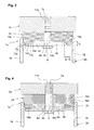
- FIG. 1 a cross-section through a die according to the invention
- FIG. 2 a cross-section through a further die according to the invention
- FIG. 3 a cross-section through a further die according to the invention.
- FIG. 4 a cross-section through a further die according to the invention.
- FIG. 5 a a top view of the collar of a die according to the invention.
- FIG. 5 b a diagrammatic cross-section through FIG. 5 a along line A—A;
- FIG. 6 a cross-section through a die according to the invention with wear protection
- FIG. 7 a cross-section through a further die according to the invention with wear protection
- FIG. 8 a cross-section through a multi-chamber profile
- FIG. 9 a a cross-section through a die according to the invention with reinforcement bush
- FIG. 9 b an enlarged extract from the area of the reinforcement bush according to FIG. 9 a;
- FIGS. 9 c-f an extract through a die according to the invention in cross-section with various reinforcement bushes.
- the die 1 a,b,c according to FIGS. 1, 2 and 3 contains a collar 2 a,b,c of polyurethane arranged on a carrier part 3 a,b,c .
- the collar 2 a,b,c has a pocket-like recess 4 a,b,c arranged on a base part 15 a,b,c and bordered on the periphery by a ring flange 5 a,b,c and towards the carrier part 3 a,b,c by the face 16 a,b,c of the base part 15 a,b,c .
- a preload plate 6 a,b,c of steel is provided in the pocket-like recess 4 a,b,c of steel.
- the preload plate 6 a,b,c , the collar 2 a,b,c and the carrier part 3 a,b,c have a mutually aligned passage opening 7 a,b,c .
- a screw 8 a,b,c with a through-bore 9 a,b,c which lies with the screw head 10 a,b,c on the preload plate 6 a,b,c and is screwed and anchored by way of a thread 11 a,b,c in the carrier plate 3 a,b,c .
- the collar 2 a,b,c contains an external wall 19 a,b,c formed by the base part 15 a,b,c and the ring flange 5 a,b,c and which tapers towards the ring flange end face 13 a,b,c.
- the collar 2 a,b,c conforms to the walls 18 of the profile chamber 20 .
- the stop point of the profile chamber face effective for the seal for the forming process lies on the tapering wall section of outer wall 19 a,b,c behind the ring flange 5 a,b,c in the base part 15 a,b,c.
- the ring flange inner wall 14 a is substantially parallel to the die longitudinal axis x.
- the edge is broken by means of a corner surface 17 a so that the ring flange 5 a towards the face end 16 a forms a foot-like expansion with maximum diameter e 1 .
- the maximum diameter e 1 of the foot-like expansion corresponds approximately to diameter d 1 of the ring flange 5 a in the area of the ring flange end face 13 a .
- the maximum diameter e 1 of the foot-like expansion also corresponds approximately to half the height h 1 of the ring flange 5 a , or is larger.
- the edges at the transition from the corner surface 17 a to the ring flange inner walls 14 a and to the face 16 a are rounded and are enclosed in an angle of the adjacent walls or surfaces of around 135°.
- the ring flange inner wall 14 b according to the embodiment in FIG. 2 is substantially parallel to the die longitudinal axis x.
- the edge is broken by means of a curved surface 17 b so that the ring flange 5 b towards the face 16 b forms a foot-like expansion with a maximum diameter e 2 .
- the radius r of the circle bordering the curved surface corresponds approximately to half the height h 2 of the ring flange 5 b or is larger.
- the maximum diameter e 2 of the foot-like expansion again corresponds approximately to diameter d 2 of the ring flange 5 b in the area of the ring flange end face 13 b . Furthermore, the maximum diameter e 2 of the foot-like expansion corresponds approximately to half the height h 2 of the ring flange 5 b , or is larger.
- the ring flange inner wall 14 c tapers starting from the face 16 c of the collar 2 c towards the ring flange end face 13 c so that the ring flange 5 c forms towards the face 16 c a foot-like expansion with the maximum diameter e 3 .
- the edge is broken in addition by means of a curved surface 17 c .
- the maximum diameter e 3 of the foot-like expansion corresponds approximately to the diameter d 3 of the ring flange 5 c in the area of the ring flange end face 13 c .
- the maximum diameter e 3 of the foot-like expansion corresponds approximately to half the height h 3 of the ring flange 5 c , or is larger.
- a further design according to FIG. 4 of the die id according to the invention contains a collar 2 d of a polyurethane, arranged on a carrier part 3 d .
- the collar 2 d substantially consists of a base part 15 d and contains on its face 16 d groove or hole-like recesses 25 .
- On the face 16 d is arranged a preload plate 6 d of steel which contains mouldings 26 corresponding to the recesses 25 .
- the mouldings 26 engage tightly in the recesses 25 and secure the preload plate 6 d against twisting about the die longitudinal axis x.
- the preload plate 6 d , the collar 2 d and the carrier part 3 d have a mutually aligned passage opening 7 d .
- a screw 8 d with a through-bore 9 d which lies with its screw head 10 d on the preload plate 6 d and by way of a thread lid is screwed and anchored into the carrier plate 3 d .
- the outer wall 19 d of the base part 15 d tapers towards the face 16 d .
- the preload plate 6 a,b,c,d Before insertion of the die 1 a,b,c,d into its operating position, the preload plate 6 a,b,c,d according to FIGS. 1, 2 , 3 , 4 is clamped by the screw 8 a,b,c,d such that the collar 2 a,b,c,d is clamped sandwich-like between the preload plate 6 a,b,c,d and the carrier part 3 a,b,c,d and where applicable undergoes a sideways expansion.
- the extent of the applied clamping force and hence the extent of the squeezing and expansion of collar 2 a,b,c,d is dependent on the existing tolerances between the collar 2 a,b,c,d and the profile chamber walls 18 .
- FIG. 5 a shows in top view a collar 2 h of the design according to the invention.
- the same collar 2 h is shown in cross-sectional view in FIG. 5 b along line A—A.
- the outer wall 19 h of the base part 15 h describes a polygonal outline which corresponds to the cross-sectional geometry of a corresponding profile chamber 20 of a multi-chamber profile 21 (see FIG. 8 ).
- the outer contour of the collar 2 h given by the outer wall 19 h is accompanied by a ring flange 5 h shown in FIG. 5 a by the ring flange end face 13 h .
- the ring flange 5 h encloses a pocket-like recess 4 h which is visible in FIG. 5 a by its face 16 h .
- Arranged centrally is a passage opening 7 h for a screw connection with through-bore for a pressure medium supply and/or extraction channel.
- the edges in the transition area of two ring flange sections intersecting at an angle are rounded in the area of the inner ring flange wall 14 h .
- Said transition area is preferably bordered by a curved piece with circle radius s.
- Said circle radius s corresponds to or is larger than half the diameter e 5 of the maximum foot-like expansion of the ring flange 5 h .
- the diameter d 5 of the ring flange end face 13 h corresponds approximately to the maximum diameter e 5 of the foot-like expansion.
- the outer wall 19 h of the base part 15 h tapers in the direction of the ring flange end face 13 h.
- a wear protection device is provided in a die 1 e produced according to the description in FIG. 3 .
- the wear protection takes the form of a strip-like wear section 30 inset into a groove-like recess 31 in the tapering outer wall 19 e of the base part 15 e .
- the outer wall of the wear strip 30 aligns with the outer wall 19 e of the base part 15 e .
- the wear strip 30 is made of steel.
- a wear protection device is provided in a die if produced according to the description in FIG. 3 .
- a plate-like intermediate part 35 with a bead-like edge 36 of steel Between the carrier part 3 f and the collar 2 f is arranged a plate-like intermediate part 35 with a bead-like edge 36 of steel.
- the bead-like edge 36 forms a wear protection on the tapering outer wall 19 f of the base part 15 f .
- the bead-like edge 36 has for this an outer surface 37 running in alignment to the outer wall 19 f i.e. tapering.
- the bead-like edge 36 thus forms a wear edge protruding into the outer wall 19 f of the base part.
- the intermediate part 35 also has a passage opening aligned with the passage opening 7 f of the preload plate 6 f , the collar 2 f and the carrier plate 3 f , for passage of a fixing bolt 8 f with a through-bore 9 f .
- the fixing means 8 f anchoring the preload plate 4 f can also be anchored in the intermediate part 35 .
- the design of the ring flange 5 e,f in FIGS. 6 and 7 and its walls 13 e,f , 14 e,f , 17 e,f and in particular the design of the transition area from the ring flange wall 14 e,f to the face 16 e,f and the anchoring of the collar 2 e,f in the carrier part 3 e,f corresponds to the statements on FIG. 3 .
- the corresponding features can be taken from the associated description.
- Said design of the ring flange 5 f and its walls, and in particular the design of the transition area from the ring flange inner wall, and the transition area can also correspond to FIGS. 1 and 2.
- the wear protection described above and its embodiments can also be applied to the design variant shown in FIG. 4 .
- FIG. 9 a shows a further embodiment of a die 1 according to the invention.
- the die contains a collar 2 of a polyurethane arranged on a carrier part 3 .
- the collar 2 has a face 16 and a peripheral ring flange 5 with a ring flange end face 13 .
- the collar 2 has an outer wall 19 , formed by the base part 15 and the ring flange 5 , which tapers towards the ring flange end face 13 .
- the design of the outer wall 19 , ring flange 5 and foot-like expansion corresponds to the description in FIG. 1 a.
- the collar 2 and the carrier part 3 have a mutually aligned passage opening 7 .
- a reinforcement bush 40 a which is formed as a hollow cylinder running d parallel to the die longitudinal axis x.
- the reinforcement bush 40 a is inset lying tightly in the passage opening 7 .
- From the direction of the face 16 a bolt 8 with a through-bore 9 is let into the passage opening or reinforcement bush 40 a .
- the bolt 8 lies with its bolt head 10 on the face end of the reinforcement bush 40 a and is screwed into the carrier plate 3 by way of a thread 11 .
- sealing ring 42 a is let into an annular groove opening and seals the separating area between the collar 2 and the carrier part 3 towards the passage opening 7 against the penetrating pressure medium.
- the collar 2 conforms to the walls 18 of the profile chamber 20 when the die 1 is in the position ready for operation.
- the stop point of the profile chamber face effective for sealing for the forming process lies on the tapering wall section of the outer wall 19 , behind the ring flange 5 in the base part 15 .
- FIG. 9 b shows an enlarged extract from the area of the reinforcement bush 40 a according to FIG. 9 a .
- An annular groove opening 43 a on the face end towards the carrier part 3 holds a sealing ring 42 a which, when the reinforcement bush 40 a makes contact by its face end with the carrier part 3 , seals the border area between the collar 2 and the carrier part 3 towards the passage opening 7 .
- FIGS. 9 c-f show various embodiments of reinforcement bushes 40 b,c,d,e which are arranged in the passage opening 7 in the base part 15 of the collar 2 .
- the embodiments of the reinforcement bushes 40 b,c,d,e according to the invention can be used in any of the dies according to the invention described above.
- the reinforcement bush 40 b is formed as a cylindrical bush running parallel to the die longitudinal axis x and has at both ends an annular collar 41 which stops the pressure medium being able to penetrate the separating area between the collar 2 and the reinforcement bush 40 b.
- the outer surface of the reinforcement bush 40 c is formed conical where the outer surface tapers towards the face 16 .
- the inner face of the reinforcement bush 40 c runs parallel to the die longitudinal axis x.
- the reinforcement bush 40 d is formed as a cylindrical bush running parallel to the die longitudinal axis x.
- the reinforcement bush 40 d is arranged about the passage opening 7 and in inset integral into the base part 15 of the collar 2 .
- the reinforcement bush 40 d can be cast or pushed in, or where applicable glued in.
- the reinforcement bush 40 e shown in the design according to FIG. 9 f is a cylindrical bush running parallel to the die longitudinal axis x with the stepped wall thickness.
- the thickening is step-like and arranged in the center area of the reinforcement bush 40 e , where the thinner wall of the reinforcement bush 40 e is arranged towards the face 16 .
- the thickening of the reinforcement bush 40 c,e towards the carrier part 3 according to FIGS. 9 d and 9 f is based on the fact that the outer wall 19 of the collar 2 towards the carrier part 3 is exposed to atmospheric pressure outside the profile chamber 20 , while the outer wall 19 of the collar 2 starting from the stop point of the profile chamber walls 18 against the face 6 lies within the profile chamber 20 and is also exposed to the internal high pressure.
- the forces acting radially in the passage opening 7 consequently cause greater radial deformation of the collar towards the carrier part 3 than towards the face 16 , so the reinforcement bush 40 d,e,f is formed to be more solid towards the carrier part 3 .
Landscapes
- Physics & Mathematics (AREA)
- Fluid Mechanics (AREA)
- Engineering & Computer Science (AREA)
- Mechanical Engineering (AREA)
- Press-Shaping Or Shaping Using Conveyers (AREA)
- Shaping Metal By Deep-Drawing, Or The Like (AREA)
- Moulds For Moulding Plastics Or The Like (AREA)
- Blow-Moulding Or Thermoforming Of Plastics Or The Like (AREA)
- Shaping Of Tube Ends By Bending Or Straightening (AREA)
- Golf Clubs (AREA)
- Accessories Of Cameras (AREA)
Applications Claiming Priority (2)
| Application Number | Priority Date | Filing Date | Title |
|---|---|---|---|
| EP00810590A EP1170069A1 (de) | 2000-07-05 | 2000-07-05 | Vorrichtung zum Umformen eines Hohlprofils mittels Innenhochdruck-Umformens |
| EP00810590.0 | 2000-07-05 |
Publications (2)
| Publication Number | Publication Date |
|---|---|
| US20020002851A1 US20020002851A1 (en) | 2002-01-10 |
| US6575007B2 true US6575007B2 (en) | 2003-06-10 |
Family
ID=8174789
Family Applications (1)
| Application Number | Title | Priority Date | Filing Date |
|---|---|---|---|
| US09/899,465 Expired - Fee Related US6575007B2 (en) | 2000-07-05 | 2001-07-05 | Device for forming a hollow profile by means of internal high pressure forming |
Country Status (5)
| Country | Link |
|---|---|
| US (1) | US6575007B2 (de) |
| EP (1) | EP1170069A1 (de) |
| AT (1) | ATE283737T1 (de) |
| DE (1) | DE50104660D1 (de) |
| ES (1) | ES2228784T3 (de) |
Cited By (2)
| Publication number | Priority date | Publication date | Assignee | Title |
|---|---|---|---|---|
| US20070022982A1 (en) * | 2005-07-26 | 2007-02-01 | Eaton Corporation | Hydroformed port liner |
| US20070107480A1 (en) * | 2003-10-15 | 2007-05-17 | Daimlerchrysler Ag | Device for forming a peripherally closed hollow profiled element by means of fluidic internal high pressure |
Families Citing this family (1)
| Publication number | Priority date | Publication date | Assignee | Title |
|---|---|---|---|---|
| DE10311180B3 (de) * | 2003-03-12 | 2004-02-12 | Forschungsgesellschaft Umformtechnik Mbh | Vorrichtung zum Abdichten der Enden eines Hohlprofils beim Innenhochdruckumformen |
Citations (18)
| Publication number | Priority date | Publication date | Assignee | Title |
|---|---|---|---|---|
| US2245887A (en) | 1940-05-14 | 1941-06-17 | Gustavus A Wikander | Stopper for laundry tubs, washbasins, and other receptacles |
| US2837810A (en) * | 1955-06-17 | 1958-06-10 | Flexonics Corp | Method of producing fittings |
| DE1068206B (de) | 1955-06-17 | 1959-11-05 | Flexonics Corporation, Maywood, 111. (V. St. A.) | Verfahren zum Herstellen eines gekrümmten Rohrformstückes |
| US4393674A (en) * | 1981-06-25 | 1983-07-19 | Air-Mo Hydraulics, Inc. | Hydraulic chuck device for engagement with the inside of a tube |
| US4660269A (en) * | 1985-05-21 | 1987-04-28 | Musashi Seimitsu Kogyo Kabushiki Kaisha | Process for producing built-up camshafts |
| EP0225573A2 (de) | 1985-12-02 | 1987-06-16 | Aluminum Company Of America | Abdichtungsvorrichtung für Hohlkörperenden |
| US4761982A (en) * | 1986-10-01 | 1988-08-09 | General Motors Corporation | Method and apparatus for forming a heat exchanger turbulator and tube |
| US5038830A (en) | 1986-06-27 | 1991-08-13 | Hydrotreat, Inc. | Pipe and sealing device |
| US5170557A (en) * | 1991-05-01 | 1992-12-15 | Benteler Industries, Inc. | Method of forming a double wall, air gap exhaust duct component |
| US5233854A (en) * | 1992-05-11 | 1993-08-10 | General Motors Corporation | Press apparatus for hydroforming a tube |
| US5303570A (en) * | 1991-02-01 | 1994-04-19 | Hde Metallwerk Gmbh | Hydrostatically deforming a hollow body |
| US5363544A (en) * | 1993-05-20 | 1994-11-15 | Benteler Industries, Inc. | Multi-stage dual wall hydroforming |
| US6065502A (en) * | 1998-10-07 | 2000-05-23 | Cosma International Inc. | Method and apparatus for wrinkle-free hydroforming of angled tubular parts |
| DE19909927A1 (de) | 1999-03-06 | 2000-09-14 | Audi Ag | Vorrichtung zum Innenhochdruckumformen eines Hohlkörpers |
| US6128936A (en) * | 1998-09-09 | 2000-10-10 | Kabushiki Kaisha Opton | Bulging device and bulging method |
| US6266986B1 (en) * | 1999-01-14 | 2001-07-31 | Nissan Motor Co., Ltd. | Nozzle for hydrostatic forming and hydrostatic forming system using same nozzle |
| US6279364B1 (en) * | 1999-02-16 | 2001-08-28 | Gary E. Morphy | Sealing method and press apparatus |
| US6397449B1 (en) * | 1993-08-16 | 2002-06-04 | Vari-Form Inc. | Method for expansion forming of tubing |
-
2000
- 2000-07-05 EP EP00810590A patent/EP1170069A1/de not_active Withdrawn
-
2001
- 2001-06-18 DE DE50104660T patent/DE50104660D1/de not_active Expired - Fee Related
- 2001-06-18 AT AT01810590T patent/ATE283737T1/de not_active IP Right Cessation
- 2001-06-18 ES ES01810590T patent/ES2228784T3/es not_active Expired - Lifetime
- 2001-07-05 US US09/899,465 patent/US6575007B2/en not_active Expired - Fee Related
Patent Citations (18)
| Publication number | Priority date | Publication date | Assignee | Title |
|---|---|---|---|---|
| US2245887A (en) | 1940-05-14 | 1941-06-17 | Gustavus A Wikander | Stopper for laundry tubs, washbasins, and other receptacles |
| US2837810A (en) * | 1955-06-17 | 1958-06-10 | Flexonics Corp | Method of producing fittings |
| DE1068206B (de) | 1955-06-17 | 1959-11-05 | Flexonics Corporation, Maywood, 111. (V. St. A.) | Verfahren zum Herstellen eines gekrümmten Rohrformstückes |
| US4393674A (en) * | 1981-06-25 | 1983-07-19 | Air-Mo Hydraulics, Inc. | Hydraulic chuck device for engagement with the inside of a tube |
| US4660269A (en) * | 1985-05-21 | 1987-04-28 | Musashi Seimitsu Kogyo Kabushiki Kaisha | Process for producing built-up camshafts |
| EP0225573A2 (de) | 1985-12-02 | 1987-06-16 | Aluminum Company Of America | Abdichtungsvorrichtung für Hohlkörperenden |
| US5038830A (en) | 1986-06-27 | 1991-08-13 | Hydrotreat, Inc. | Pipe and sealing device |
| US4761982A (en) * | 1986-10-01 | 1988-08-09 | General Motors Corporation | Method and apparatus for forming a heat exchanger turbulator and tube |
| US5303570A (en) * | 1991-02-01 | 1994-04-19 | Hde Metallwerk Gmbh | Hydrostatically deforming a hollow body |
| US5170557A (en) * | 1991-05-01 | 1992-12-15 | Benteler Industries, Inc. | Method of forming a double wall, air gap exhaust duct component |
| US5233854A (en) * | 1992-05-11 | 1993-08-10 | General Motors Corporation | Press apparatus for hydroforming a tube |
| US5363544A (en) * | 1993-05-20 | 1994-11-15 | Benteler Industries, Inc. | Multi-stage dual wall hydroforming |
| US6397449B1 (en) * | 1993-08-16 | 2002-06-04 | Vari-Form Inc. | Method for expansion forming of tubing |
| US6128936A (en) * | 1998-09-09 | 2000-10-10 | Kabushiki Kaisha Opton | Bulging device and bulging method |
| US6065502A (en) * | 1998-10-07 | 2000-05-23 | Cosma International Inc. | Method and apparatus for wrinkle-free hydroforming of angled tubular parts |
| US6266986B1 (en) * | 1999-01-14 | 2001-07-31 | Nissan Motor Co., Ltd. | Nozzle for hydrostatic forming and hydrostatic forming system using same nozzle |
| US6279364B1 (en) * | 1999-02-16 | 2001-08-28 | Gary E. Morphy | Sealing method and press apparatus |
| DE19909927A1 (de) | 1999-03-06 | 2000-09-14 | Audi Ag | Vorrichtung zum Innenhochdruckumformen eines Hohlkörpers |
Cited By (3)
| Publication number | Priority date | Publication date | Assignee | Title |
|---|---|---|---|---|
| US20070107480A1 (en) * | 2003-10-15 | 2007-05-17 | Daimlerchrysler Ag | Device for forming a peripherally closed hollow profiled element by means of fluidic internal high pressure |
| US20070022982A1 (en) * | 2005-07-26 | 2007-02-01 | Eaton Corporation | Hydroformed port liner |
| US7305763B2 (en) | 2005-07-26 | 2007-12-11 | Board Of Trustees Of Michigan State University | Hydroformed port liner |
Also Published As
| Publication number | Publication date |
|---|---|
| DE50104660D1 (de) | 2005-01-05 |
| US20020002851A1 (en) | 2002-01-10 |
| EP1170069A1 (de) | 2002-01-09 |
| ATE283737T1 (de) | 2004-12-15 |
| ES2228784T3 (es) | 2005-04-16 |
Similar Documents
| Publication | Publication Date | Title |
|---|---|---|
| US3835523A (en) | Self-straining bolts | |
| US5920035A (en) | High pressure seal | |
| US5454675A (en) | Sealing nut and method of making same | |
| US5335946A (en) | Cooperating combination of a gland and a grip ring installed in restrained sealed bolted joints of fluid piping systems including both plastic pipe and metallic pipe | |
| CZ303737B6 (cs) | Tesnicí krouzek | |
| US4191389A (en) | Sealing washer | |
| US4850096A (en) | Method of joining pipes | |
| CN101379336A (zh) | 用于高压和高纯度气体通道的密封法兰接头 | |
| US6575007B2 (en) | Device for forming a hollow profile by means of internal high pressure forming | |
| US4950002A (en) | Screw seal | |
| KR100195820B1 (ko) | 자기 작동 밸브를 하우징 블록에 접속하는 포지티브 접속 장치와, 포지티브 접속 장치 형성방법 | |
| US6588762B2 (en) | Lathe cut face seal and method for sealing irregularly shaped cavity | |
| US2216291A (en) | Piston | |
| US5375507A (en) | Hydraulic cylinder | |
| US5577406A (en) | Forming tool | |
| JP4315330B2 (ja) | 流体管の離脱防止装置 | |
| US3937500A (en) | Device for connecting telescoping pipes | |
| US7797806B2 (en) | Internal high-pressure shaping method for shaping conical tubes made of metal | |
| EP1356220B1 (de) | Hochdruckdichtung | |
| KR20060127833A (ko) | 금형 냉각수관 마개 | |
| RU2386888C1 (ru) | Соединение трубопроводов | |
| KR102261391B1 (ko) | 시일 구조 및 시일 방법과 이 시일 구조를 갖는 커플링 | |
| CN215568053U (zh) | 一种防微泄漏闸阀 | |
| HK1210255A1 (en) | Hydraulic connecting bush, hydraulic connection, and hydraulic plug | |
| KR200333861Y1 (ko) | 파이프의 단부 밀폐용 마개 |
Legal Events
| Date | Code | Title | Description |
|---|---|---|---|
| AS | Assignment |
Owner name: ALUSUISSE TECHNOLOGY & MANAGEMENT LTD., SWITZERLAN Free format text: ASSIGNMENT OF ASSIGNORS INTEREST;ASSIGNORS:HEIN, JORG;ROST, ANDRE;GOGER, ASLAN;REEL/FRAME:011971/0987;SIGNING DATES FROM 20010607 TO 20010612 |
|
| AS | Assignment |
Owner name: ALCAN TECHNOLOGY & MANAGEMENT LTD., SWITZERLAND Free format text: CHANGE OF NAME;ASSIGNOR:ALUSUISSE TECHNOLOGY & MANAGEMENT LTD.;REEL/FRAME:013064/0741 Effective date: 20020226 |
|
| REMI | Maintenance fee reminder mailed | ||
| LAPS | Lapse for failure to pay maintenance fees | ||
| STCH | Information on status: patent discontinuation |
Free format text: PATENT EXPIRED DUE TO NONPAYMENT OF MAINTENANCE FEES UNDER 37 CFR 1.362 |
|
| FP | Lapsed due to failure to pay maintenance fee |
Effective date: 20070610 |