US6547252B1 - Housing having a recess for locating part of a sealing material - Google Patents
Housing having a recess for locating part of a sealing material Download PDFInfo
- Publication number
- US6547252B1 US6547252B1 US09/582,810 US58281000A US6547252B1 US 6547252 B1 US6547252 B1 US 6547252B1 US 58281000 A US58281000 A US 58281000A US 6547252 B1 US6547252 B1 US 6547252B1
- Authority
- US
- United States
- Prior art keywords
- housing
- sealing profile
- sealing
- receiving area
- forming
- Prior art date
- Legal status (The legal status is an assumption and is not a legal conclusion. Google has not performed a legal analysis and makes no representation as to the accuracy of the status listed.)
- Expired - Fee Related
Links
- 239000003566 sealing material Substances 0.000 title claims abstract description 18
- 238000007789 sealing Methods 0.000 claims abstract description 39
- 235000011837 pasties Nutrition 0.000 claims abstract description 3
- 238000000034 method Methods 0.000 claims description 8
- 125000006850 spacer group Chemical group 0.000 claims description 6
- 239000004033 plastic Substances 0.000 claims description 4
- 238000005266 casting Methods 0.000 claims description 3
- 238000000576 coating method Methods 0.000 claims description 3
- 238000001125 extrusion Methods 0.000 claims description 3
- 239000011248 coating agent Substances 0.000 claims description 2
- 239000006260 foam Substances 0.000 claims 1
- 230000013011 mating Effects 0.000 claims 1
- 239000000126 substance Substances 0.000 abstract description 2
- 239000007788 liquid Substances 0.000 abstract 1
- 239000000463 material Substances 0.000 description 9
- 238000004519 manufacturing process Methods 0.000 description 6
- 230000000694 effects Effects 0.000 description 3
- 230000006835 compression Effects 0.000 description 2
- 238000007906 compression Methods 0.000 description 2
- 238000003780 insertion Methods 0.000 description 2
- 230000037431 insertion Effects 0.000 description 2
- 238000010079 rubber tapping Methods 0.000 description 2
- XAGFODPZIPBFFR-UHFFFAOYSA-N aluminium Chemical group [Al] XAGFODPZIPBFFR-UHFFFAOYSA-N 0.000 description 1
- 229910052782 aluminium Inorganic materials 0.000 description 1
- 230000003466 anti-cipated effect Effects 0.000 description 1
- 239000011324 bead Substances 0.000 description 1
- 239000004020 conductor Substances 0.000 description 1
- 230000008021 deposition Effects 0.000 description 1
- 239000013013 elastic material Substances 0.000 description 1
- 230000008030 elimination Effects 0.000 description 1
- 238000003379 elimination reaction Methods 0.000 description 1
- 239000003000 extruded plastic Substances 0.000 description 1
- 238000005259 measurement Methods 0.000 description 1
- 238000003801 milling Methods 0.000 description 1
- 230000001151 other effect Effects 0.000 description 1
- 239000003973 paint Substances 0.000 description 1
- 230000035484 reaction time Effects 0.000 description 1
- 238000007493 shaping process Methods 0.000 description 1
- 239000002904 solvent Substances 0.000 description 1
- 238000005507 spraying Methods 0.000 description 1
- 239000007858 starting material Substances 0.000 description 1
- 239000000080 wetting agent Substances 0.000 description 1
Images


Classifications
-
- H—ELECTRICITY
- H05—ELECTRIC TECHNIQUES NOT OTHERWISE PROVIDED FOR
- H05K—PRINTED CIRCUITS; CASINGS OR CONSTRUCTIONAL DETAILS OF ELECTRIC APPARATUS; MANUFACTURE OF ASSEMBLAGES OF ELECTRICAL COMPONENTS
- H05K9/00—Screening of apparatus or components against electric or magnetic fields
- H05K9/0007—Casings
- H05K9/0015—Gaskets or seals
-
- H—ELECTRICITY
- H05—ELECTRIC TECHNIQUES NOT OTHERWISE PROVIDED FOR
- H05K—PRINTED CIRCUITS; CASINGS OR CONSTRUCTIONAL DETAILS OF ELECTRIC APPARATUS; MANUFACTURE OF ASSEMBLAGES OF ELECTRICAL COMPONENTS
- H05K9/00—Screening of apparatus or components against electric or magnetic fields
-
- H—ELECTRICITY
- H01—ELECTRIC ELEMENTS
- H01Q—ANTENNAS, i.e. RADIO AERIALS
- H01Q1/00—Details of, or arrangements associated with, antennas
- H01Q1/12—Supports; Mounting means
- H01Q1/22—Supports; Mounting means by structural association with other equipment or articles
- H01Q1/24—Supports; Mounting means by structural association with other equipment or articles with receiving set
- H01Q1/241—Supports; Mounting means by structural association with other equipment or articles with receiving set used in mobile communications, e.g. GSM
- H01Q1/242—Supports; Mounting means by structural association with other equipment or articles with receiving set used in mobile communications, e.g. GSM specially adapted for hand-held use
- H01Q1/245—Supports; Mounting means by structural association with other equipment or articles with receiving set used in mobile communications, e.g. GSM specially adapted for hand-held use with means for shaping the antenna pattern, e.g. in order to protect user against rf exposure
-
- H—ELECTRICITY
- H04—ELECTRIC COMMUNICATION TECHNIQUE
- H04B—TRANSMISSION
- H04B1/00—Details of transmission systems, not covered by a single one of groups H04B3/00 - H04B13/00; Details of transmission systems not characterised by the medium used for transmission
- H04B1/38—Transceivers, i.e. devices in which transmitter and receiver form a structural unit and in which at least one part is used for functions of transmitting and receiving
- H04B1/3827—Portable transceivers
- H04B1/3833—Hand-held transceivers
-
- H—ELECTRICITY
- H04—ELECTRIC COMMUNICATION TECHNIQUE
- H04M—TELEPHONIC COMMUNICATION
- H04M1/00—Substation equipment, e.g. for use by subscribers
- H04M1/02—Constructional features of telephone sets
- H04M1/0202—Portable telephone sets, e.g. cordless phones, mobile phones or bar type handsets
-
- H—ELECTRICITY
- H04—ELECTRIC COMMUNICATION TECHNIQUE
- H04B—TRANSMISSION
- H04B1/00—Details of transmission systems, not covered by a single one of groups H04B3/00 - H04B13/00; Details of transmission systems not characterised by the medium used for transmission
- H04B1/38—Transceivers, i.e. devices in which transmitter and receiver form a structural unit and in which at least one part is used for functions of transmitting and receiving
- H04B2001/3894—Waterproofing of transmission device
Definitions
- the invention relates to a housing according to the generic portion of claim 1 .
- Such a housing is known from DE 43 19 965 C2.
- housings of this type have been produced primarily from plastic for reasons of price and weight since the beginning of the extensive spread of mobile telephones or cordless telephones.
- the prefabricated, especially extruded, housing parts are coated with a conductive material to produce an electromagnetic shielding effect, possibly by spraying with conductive paint, deposition of aluminum, or galvanization. Then, a likewise shielding seal is dispensed thereon, and after insertion of the electronic function groups, the housing parts are connected to each other, usually screwed.
- the shielding seal consists of an electrically conductive, elastic material and must be executed in its geometric dimensions and mechanical properties such that it adapts to surface tolerances and unevenness, such that even with the tolerances present in mass production, a very high quality of shielding of the interior of the housing is guaranteed.
- the dispensing element e.g., a hollow needle
- the distance changes by 16% per 0.1 mm dimensional deviation of the housing part. Accordingly, more dispensed material would have to be applied on the surface in order to obtain a constant height of the housing part-sealing profile part system. This could be realized using an expensive measurement and control apparatus; however, such a solution is both technically and temporally impracticable in mass production.
- the object of the invention is, therefore, to provide a housing of the type mentioned which can be produced more simply and economically while meeting the tolerance specifications customary in mass production.
- the object is accomplished by a housing with the characteristics of claim 1 .
- the invention includes the technical teaching of providing, on the housing, as an integrated component of the sealing system, a receiving area for a safety-excess of the sealing material. This enables an increase in the admissible tolerances of the housing parts as well as the control of the dispenser heads and/or the elimination of any retouching of the hardened sealing profile.
- the invention provides special cost advantages when the first and/or second housing part is a cast or extruded part, especially made of plastic with the large tolerances customary therewith—above all when the recess serving as a receiving area is already formed in the first housing part at the time of casting or extrusion.
- This receiving area may—depending on the actual housing specification—be arranged both in alignment with the longitudinal extension of the sealing profile and laterally offset relative thereto. It can be open on the side or closed all the way around (e.g., an open or closed hole).
- the sealing “bead” runs in certain applications preferably at angle to the direction of the further extension of the profile.
- an incline or an edge is provided on the recess in order to achieve improved grip of the strand of sealing material with the recess during application (possibly a type of interlocking) and to counteract a possible “slip off” of the initial point which may occur with certain housing-seal-material pairs or with a contaminated surface.
- the recess can be formed in connection with an opening provided for the location of a connection means to connect the first and second housing parts. This configuration can also be used advantageously for an additional seal in this area.
- the recess is directly adjacent to an incompressible spacer on the surface of the first housing part protruding toward the second housing part. This is expediently formed during primary forming of the housing part from the housing material.
- EMI-shielding and sealing profile which has an electrically conductive sealing material and with housing parts made of plastic with substantially all-over conductive coating of the surface which is in contact with the sealing profile.
- the invention is, however, not restricted to such shielding housings but may advantageously also be applied in dust- or watertight housings.
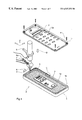
- FIG. 1 a principal sketch for the embodiment of the invention
- FIG. 1 a a detail from FIG. 1,
- FIGS. 2 a through 2 f schematic depictions of different examples of housing sections with recesses in longitudinal section or in top view
- FIGS. 3 a through 3 i schematic depictions of three improved embodiments, each in a top view and in a cross-sectional depiction of a housing section as well as in the state with the double strand of sealing material applied, and
- FIGS. 4 a and 4 b schematic depictions of two additional embodiments of the invention.
- FIG. 1 depicts schematically a bottom housing part 1 and a top housing part 2 of a mobile phone housing 3 made of extruded plastic, both of which are provided with an inside metalizing layer 1 a and 2 a , respectively.
- Screw holes 1 b and 2 b are formed in both housing parts 1 , 2 , whereby the screw holes 1 b in the bottom housing part are designed for partial self-tapping insertion of self-tapping screws 4 .
- an arm 5 of a coordinate-controlled handling apparatus guides an application needle 6 with a hose connection 6 a to deliver a pressurized conductive seal starting material 7 in the direction of the arrow A over the edge section of the bottom housing part 1 .
- a sealing and shielding material strand 8 is dispensed onto the edge section and adheres tightly there upon hardening.
- the top part 2 is placed on the bottom part 1 —as symbolized by the arrow B—and screwed to it by means of the screws 6 , whereby the strand solidified into the sealing and shielding profile 8 is elastically deformed without adhesion on the top part 2 and reliably seals and electromagnetically shields the gap between the housing parts 1 , 2 .
- a recess 9 in the form of an elongated hole which is better discernible in the enlarged depiction of the section C in FIG. 1 a , is incorporated in the section C of the edge area of the bottom housing 3 part 1 .
- the elongated hole 9 defines the initial and also the final point of the application of the shielding profile 8 , where, to ensure a reliable all-around seal, in each case an increased amount of material is discharged from the application needle 6 and partially received in the elongated hole.
- FIGS. 2 a through 2 f depict schematically examples of housing sections of housing parts 11 , 21 , 31 , 41 , and 51 , respectively, with recesses 19 , 29 , 39 , 49 , and 59 , respectively, provided as initial areas in longitudinal cross-section (FIGS. 2 a and 2 c through 2 e ) or in a top view (FIG. 2 b as a top view of FIG. 2 a ).
- the recess can be implemented depending on the actual technological edge conditions as a simple blind hole with a bottom parallel to the surface of the housing part (FIGS.
- one or a plurality of projections can be associated with it on the housing surface, such as the spacer 49 a associated with the initial zone 49 in FIG. 2 e and the incline 49 b or the retaining hip 59 a associated with a semicircular trough 59 in the housing part 51 .
- such projections have the function of improving adhesion especially at the initial point of a sealing material strand, especially with problematic surface conditions and/or housing-seal material pairings. Even a sharp edged embodiment of the edge of the recess itself can serve this purpose to certain extent.
- FIGS. 3 a through 3 i depict schematically three additional exemplary embodiments, each in a top view (FIGS. 3 a , 3 d , and 3 g ) and in a cross-sectional view (FIGS. 3 b , 3 e , and 3 h ) of a housing section 61 , 71 , and 81 , respectively, as well as in the state with the double strand of sealing material applied 68 a / 68 b , 78 a / 78 b , and 88 a / 88 b , respectively, (FIGS. 3 c , 3 f , and 3 i ).
- the recesses 69 , 79 , and 89 have a substantially rectangular cross-section here, whereby the recess 89 has one completely open side face and the recess 79 has an open side access, such that with the corresponding housing parts 81 and 71 , respectively, a sealing material application can take place pivoting in from the open side into the seal path (or pivoting out from it), whereby the initial or final point is thus offset relative to the longitudinal extension of the sealing profile.
- the bottom of the recess 79 in the area of its side opening and the bottom of the recess 89 are depicted completely flat; in modified embodiments, it can, however, be designed sloping upward toward the open side in order to prevent run-out of the not yet hardened sealing material, in the event that sealing material with a relatively low viscosity is used.
- the spacer (reference character 69 a , 79 a , or 89 a ) depicted in FIGS. 3 a through 3 i has a height of approximately 80% of the planned height of the sealing profile to limit its compression upon closing of the housing; the selection of this relationship depends, however, on the actual application, in particular on the elasticity and hardness of the sealing profile.
- FIGS. 4 a and 4 b schematically depict top views of two additional embodiments of the receiving area.
- FIG. 4 a depicts an application surface 99 formed on the side of a housing part 91 in the vicinity of a spacer 99 a and somewhat lowered relative to the housing surface, which constitutes a initial point for the application of a sealing profile 98 ; and
- FIG. 4 b a similar embodiment where the application surface 109 is, however, formed at the same level as the surface of the housing part 101 and also has a reservoir trough 109 b.
- a receiving area with the described function of evening out the profile height and thus the sealing and shielding effect over the entire path around housing edge can be embodied in extremely different shapes and can also be provided, in particular, on sealing profile bifurcation points.
- the material properties of the sealing and shielding mass both in the initial pasty state (especially its running properties on the housing surface) and in the final state (especially compressibility and elasticity) must be taken into account in order to realize the ultimately critical functional aspect of a uniform sealing and shielding action over the entire course of the housing area to be sealed.
Landscapes
- Engineering & Computer Science (AREA)
- Signal Processing (AREA)
- Computer Networks & Wireless Communication (AREA)
- Microelectronics & Electronic Packaging (AREA)
- Shielding Devices Or Components To Electric Or Magnetic Fields (AREA)
- Casings For Electric Apparatus (AREA)
- Catching Or Destruction (AREA)
- Glass Compositions (AREA)
- Dry Shavers And Clippers (AREA)
Applications Claiming Priority (3)
| Application Number | Priority Date | Filing Date | Title |
|---|---|---|---|
| DE19804861 | 1998-02-09 | ||
| DE19804861 | 1998-02-09 | ||
| PCT/DE1998/003167 WO1999040769A1 (fr) | 1998-02-09 | 1998-10-24 | Boitier |
Publications (1)
| Publication Number | Publication Date |
|---|---|
| US6547252B1 true US6547252B1 (en) | 2003-04-15 |
Family
ID=7856923
Family Applications (1)
| Application Number | Title | Priority Date | Filing Date |
|---|---|---|---|
| US09/582,810 Expired - Fee Related US6547252B1 (en) | 1998-02-09 | 1998-10-24 | Housing having a recess for locating part of a sealing material |
Country Status (14)
| Country | Link |
|---|---|
| US (1) | US6547252B1 (fr) |
| EP (1) | EP1055356B1 (fr) |
| JP (1) | JP2002503043A (fr) |
| KR (1) | KR20010033570A (fr) |
| CN (1) | CN1284256A (fr) |
| AT (1) | ATE212177T1 (fr) |
| AU (1) | AU734963B2 (fr) |
| CA (1) | CA2304943A1 (fr) |
| DE (3) | DE29819434U1 (fr) |
| DK (1) | DK1055356T3 (fr) |
| ES (1) | ES2172256T3 (fr) |
| HU (1) | HUP0004680A3 (fr) |
| NO (1) | NO20003998L (fr) |
| WO (1) | WO1999040769A1 (fr) |
Cited By (8)
| Publication number | Priority date | Publication date | Assignee | Title |
|---|---|---|---|---|
| US20040262851A1 (en) * | 2003-06-25 | 2004-12-30 | Matt Tones | Rebuildable composite seal |
| US20050023022A1 (en) * | 2001-03-28 | 2005-02-03 | Michael Kriege | Computer enclosure |
| EP1659846A1 (fr) * | 2004-11-19 | 2006-05-24 | Knürr AG | Fixation étanche d'un couvercle au moyen d'une mousse |
| US20100091442A1 (en) * | 2008-10-13 | 2010-04-15 | Matthew Theobald | Portable computer unified top case |
| US20110226521A1 (en) * | 2010-03-16 | 2011-09-22 | Wertz Jr Robert Harrison | Electrical connector assembly with emi gasket |
| US20120033357A1 (en) * | 2010-08-09 | 2012-02-09 | Hon Hai Precision Industry Co., Ltd. | Electronic device housing and manufacturing method thereof |
| US20160034003A1 (en) * | 2014-08-01 | 2016-02-04 | Shenzhen Futaihong Precision Industry Co., Ltd. | Electronic device |
| US10492347B2 (en) | 2013-07-05 | 2019-11-26 | Bayerische Motoren Werke Aktiengesellschaft | Method for producing a housing having shielding against electric and/or magnetic radiation, and housing having the shielding |
Families Citing this family (10)
| Publication number | Priority date | Publication date | Assignee | Title |
|---|---|---|---|---|
| EP1115173A3 (fr) * | 1999-11-03 | 2003-04-09 | Q-Free MagCom AS | Appareil de communication radio portable comme téléphone mobile |
| WO2002021890A1 (fr) * | 2000-09-07 | 2002-03-14 | Emi-Tec Elektronische Materialien Gmbh | Procede de production d'un boitier muni d'un blindage electromagnetique et outil de formage et systeme pour mettre ledit procede en oeuvre |
| FI111116B (fi) * | 2000-10-30 | 2003-05-30 | It Innovations Finland Oy | Matkapuhelimen kuoren valmistusmenetelmä |
| DE10232947A1 (de) | 2002-07-19 | 2004-01-29 | Siemens Ag | Behältnis, insbesondere Gehäuse für ein Telefonmobilteil sowie Verfahren zur Herstellung eines Gehäuseteils |
| US7326862B2 (en) | 2003-02-13 | 2008-02-05 | Parker-Hannifin Corporation | Combination metal and plastic EMI shield |
| US7005573B2 (en) | 2003-02-13 | 2006-02-28 | Parker-Hannifin Corporation | Composite EMI shield |
| JP4355652B2 (ja) * | 2004-12-27 | 2009-11-04 | 埼玉日本電気株式会社 | 電子機器及びその防塵構造 |
| CN101600330B (zh) * | 2008-06-03 | 2012-04-18 | 上海贝尔股份有限公司 | 用于面板间电磁屏蔽的结构及其制造方法 |
| CN103939794A (zh) * | 2014-03-12 | 2014-07-23 | 嘉兴市朗特隆光电有限公司 | 一种密封方法及采用该方法的led投光灯 |
| DE102015212680B4 (de) | 2015-07-07 | 2017-02-02 | Robert Bosch Gmbh | Vorrichtung zur Fixierung eines Fügepartners mit einem Fixierelement und einem Ausgleichselement sowie Verfahren zur Herstellung dieser Vorrichtung |
Citations (13)
| Publication number | Priority date | Publication date | Assignee | Title |
|---|---|---|---|---|
| US3469015A (en) * | 1967-01-13 | 1969-09-23 | Sierracin Corp | Conductive panel |
| US4825015A (en) * | 1987-02-07 | 1989-04-25 | U.S. Philips Corporation | Electromagnetic shielding arrangement |
| US4841102A (en) * | 1987-02-07 | 1989-06-20 | U.S. Philips Corporation | Electromagnetic shielding arrangement |
| US4931479A (en) * | 1988-11-07 | 1990-06-05 | Chomerics, Inc. | Foam in place conductive polyurethane foam |
| DE4319965A1 (de) | 1993-06-14 | 1994-12-15 | Emi Tec Elektronische Material | Verfahren zur Herstellung eines eine Abschirmung gegen elektromagnetische Abstrahlung aufweisenden Gehäuses |
| US5513996A (en) * | 1994-09-20 | 1996-05-07 | Motorola, Inc. | Clip and method therefor |
| US5641438A (en) | 1995-01-24 | 1997-06-24 | Bunyan; Michael H. | Method for forming an EMI shielding gasket |
| WO1998006246A1 (fr) | 1996-08-01 | 1998-02-12 | Helmut Kahl | Procede pour produire une garniture d'etancheite a effet d'ecran electromagnetique |
| US5847317A (en) * | 1997-04-30 | 1998-12-08 | Ericsson Inc. | Plated rubber gasket for RF shielding |
| US6096413A (en) * | 1993-09-10 | 2000-08-01 | Chomerics, Inc. | Form-in-place EMI gaskets |
| US6222122B1 (en) * | 1998-01-13 | 2001-04-24 | Sun Microsystems, Inc. | Sealed liquid-filled module and method of forming same |
| US6224058B1 (en) * | 1997-08-21 | 2001-05-01 | Dichtungstechnik G. Bruss Gmbh & Co. | Static sealing arrangement |
| US6239359B1 (en) * | 1999-05-11 | 2001-05-29 | Lucent Technologies, Inc. | Circuit board RF shielding |
-
1998
- 1998-10-24 EP EP98962191A patent/EP1055356B1/fr not_active Expired - Lifetime
- 1998-10-24 ES ES98962191T patent/ES2172256T3/es not_active Expired - Lifetime
- 1998-10-24 CA CA002304943A patent/CA2304943A1/fr not_active Abandoned
- 1998-10-24 DK DK98962191T patent/DK1055356T3/da active
- 1998-10-24 US US09/582,810 patent/US6547252B1/en not_active Expired - Fee Related
- 1998-10-24 JP JP2000531047A patent/JP2002503043A/ja active Pending
- 1998-10-24 AU AU17484/99A patent/AU734963B2/en not_active Ceased
- 1998-10-24 DE DE29819434U patent/DE29819434U1/de not_active Expired - Lifetime
- 1998-10-24 DE DE19882208T patent/DE19882208D2/de not_active Expired - Fee Related
- 1998-10-24 WO PCT/DE1998/003167 patent/WO1999040769A1/fr not_active Application Discontinuation
- 1998-10-24 CN CN98813460A patent/CN1284256A/zh active Pending
- 1998-10-24 KR KR1020007007080A patent/KR20010033570A/ko not_active Application Discontinuation
- 1998-10-24 AT AT98962191T patent/ATE212177T1/de not_active IP Right Cessation
- 1998-10-24 DE DE59802680T patent/DE59802680D1/de not_active Expired - Fee Related
- 1998-10-24 HU HU0004680A patent/HUP0004680A3/hu unknown
-
2000
- 2000-08-08 NO NO20003998A patent/NO20003998L/no not_active Application Discontinuation
Patent Citations (15)
| Publication number | Priority date | Publication date | Assignee | Title |
|---|---|---|---|---|
| US3469015A (en) * | 1967-01-13 | 1969-09-23 | Sierracin Corp | Conductive panel |
| US4825015A (en) * | 1987-02-07 | 1989-04-25 | U.S. Philips Corporation | Electromagnetic shielding arrangement |
| US4841102A (en) * | 1987-02-07 | 1989-06-20 | U.S. Philips Corporation | Electromagnetic shielding arrangement |
| US4931479A (en) * | 1988-11-07 | 1990-06-05 | Chomerics, Inc. | Foam in place conductive polyurethane foam |
| US4931479B1 (en) * | 1988-11-07 | 2000-10-10 | Parker Intangibles Inc | Foam in place conductive polyurethane foam |
| US5882729A (en) | 1993-06-14 | 1999-03-16 | Emi-Tec Elektronische Materialien, Gmbh | Process for producing a casing providing a screen against electromagnetic radiation |
| DE4319965A1 (de) | 1993-06-14 | 1994-12-15 | Emi Tec Elektronische Material | Verfahren zur Herstellung eines eine Abschirmung gegen elektromagnetische Abstrahlung aufweisenden Gehäuses |
| US6096413A (en) * | 1993-09-10 | 2000-08-01 | Chomerics, Inc. | Form-in-place EMI gaskets |
| US5513996A (en) * | 1994-09-20 | 1996-05-07 | Motorola, Inc. | Clip and method therefor |
| US5641438A (en) | 1995-01-24 | 1997-06-24 | Bunyan; Michael H. | Method for forming an EMI shielding gasket |
| WO1998006246A1 (fr) | 1996-08-01 | 1998-02-12 | Helmut Kahl | Procede pour produire une garniture d'etancheite a effet d'ecran electromagnetique |
| US5847317A (en) * | 1997-04-30 | 1998-12-08 | Ericsson Inc. | Plated rubber gasket for RF shielding |
| US6224058B1 (en) * | 1997-08-21 | 2001-05-01 | Dichtungstechnik G. Bruss Gmbh & Co. | Static sealing arrangement |
| US6222122B1 (en) * | 1998-01-13 | 2001-04-24 | Sun Microsystems, Inc. | Sealed liquid-filled module and method of forming same |
| US6239359B1 (en) * | 1999-05-11 | 2001-05-29 | Lucent Technologies, Inc. | Circuit board RF shielding |
Cited By (19)
| Publication number | Priority date | Publication date | Assignee | Title |
|---|---|---|---|---|
| US20050023022A1 (en) * | 2001-03-28 | 2005-02-03 | Michael Kriege | Computer enclosure |
| US20070109737A1 (en) * | 2001-03-28 | 2007-05-17 | Apple Computer, Inc. | Computer enclosure |
| US7310872B2 (en) * | 2001-03-28 | 2007-12-25 | Apple Inc. | Computer enclosure |
| US7636244B2 (en) * | 2001-03-28 | 2009-12-22 | Apple Inc. | Computer enclosure |
| US20040262851A1 (en) * | 2003-06-25 | 2004-12-30 | Matt Tones | Rebuildable composite seal |
| EP1659846A1 (fr) * | 2004-11-19 | 2006-05-24 | Knürr AG | Fixation étanche d'un couvercle au moyen d'une mousse |
| US20100091442A1 (en) * | 2008-10-13 | 2010-04-15 | Matthew Theobald | Portable computer unified top case |
| US10474189B2 (en) | 2008-10-13 | 2019-11-12 | Apple Inc. | Portable computer unified top case |
| US8341832B2 (en) | 2008-10-13 | 2013-01-01 | Apple Inc. | Method to create an enclosure for an electronic device |
| US8687359B2 (en) | 2008-10-13 | 2014-04-01 | Apple Inc. | Portable computer unified top case |
| US11675388B2 (en) | 2008-10-13 | 2023-06-13 | Apple Inc. | Portable computer unified top case |
| US11112825B2 (en) | 2008-10-13 | 2021-09-07 | Apple Inc. | Portable computer unified top case |
| US10152081B2 (en) | 2008-10-13 | 2018-12-11 | Apple Inc. | Portable computer unified top case |
| US20110226521A1 (en) * | 2010-03-16 | 2011-09-22 | Wertz Jr Robert Harrison | Electrical connector assembly with emi gasket |
| US8203084B2 (en) * | 2010-03-16 | 2012-06-19 | Tyco Electronics Corporation | Electrical connector assembly with EMI gasket |
| US20120033357A1 (en) * | 2010-08-09 | 2012-02-09 | Hon Hai Precision Industry Co., Ltd. | Electronic device housing and manufacturing method thereof |
| US8737045B2 (en) * | 2010-08-09 | 2014-05-27 | Fu Tai Hua Industry (Shenzhen) Co., Ltd. | Electronic device housing and manufacturing method thereof |
| US10492347B2 (en) | 2013-07-05 | 2019-11-26 | Bayerische Motoren Werke Aktiengesellschaft | Method for producing a housing having shielding against electric and/or magnetic radiation, and housing having the shielding |
| US20160034003A1 (en) * | 2014-08-01 | 2016-02-04 | Shenzhen Futaihong Precision Industry Co., Ltd. | Electronic device |
Also Published As
| Publication number | Publication date |
|---|---|
| CA2304943A1 (fr) | 1999-08-12 |
| EP1055356A1 (fr) | 2000-11-29 |
| AU734963B2 (en) | 2001-06-28 |
| AU1748499A (en) | 1999-08-23 |
| KR20010033570A (ko) | 2001-04-25 |
| CN1284256A (zh) | 2001-02-14 |
| NO20003998L (no) | 2000-10-06 |
| ES2172256T3 (es) | 2002-09-16 |
| DE29819434U1 (de) | 1999-02-18 |
| HUP0004680A1 (hu) | 2001-04-28 |
| ATE212177T1 (de) | 2002-02-15 |
| JP2002503043A (ja) | 2002-01-29 |
| HUP0004680A3 (en) | 2004-01-28 |
| DE19882208D2 (de) | 2000-08-10 |
| EP1055356B1 (fr) | 2002-01-16 |
| NO20003998D0 (no) | 2000-08-08 |
| DK1055356T3 (da) | 2002-04-02 |
| WO1999040769A1 (fr) | 1999-08-12 |
| DE59802680D1 (de) | 2002-02-21 |
Similar Documents
| Publication | Publication Date | Title |
|---|---|---|
| US6547252B1 (en) | Housing having a recess for locating part of a sealing material | |
| US5358773A (en) | Adhesive structure | |
| US6323418B1 (en) | Electrically screening housing | |
| US5256833A (en) | Metal housing for electronic devices and method of producing such a housing | |
| WO2004009869A3 (fr) | Revetement inhibiteur de corrosion | |
| EP1050603A4 (fr) | Feuille d'acier traitee en surface presentant une excellente resistance a la corrosion et son procede de production | |
| WO2002053298A3 (fr) | Agent d'enduction | |
| CA1261209A (fr) | Methode et systeme de peinturage des rives apparentes de boites de conserverie | |
| US6254939B1 (en) | Method for coating an electrical contact with a gel sealant | |
| JPS6318095A (ja) | 連結された金属部品および/または金属被覆製品に金属堆積層を電解メツキする方法および装置 | |
| IL164300A0 (en) | Method for coating metal surfaces and substrate having a coated metal surface | |
| CA2370362A1 (fr) | Bains d'electrodeposition contenant de l'yttrium | |
| US20040071970A1 (en) | Device housing having a shielding gasket or wall comprising a conductive coating | |
| WO2003012175A3 (fr) | Procede pour la galvanisation selective d'un materiau support metallique en forme de bande | |
| KR100830970B1 (ko) | 도금정착잉크 | |
| KR960041422A (ko) | 도장 강판의 제조방법 | |
| KR100771415B1 (ko) | 무선통신 제품의 전자파 emi 차폐용 전도성 코팅 및페인팅 방법 | |
| EP2042621A1 (fr) | Produit métallique recouvert et son procédé de fabrication | |
| FR2704560B1 (fr) | Procede d'electrodeposition sur une surface d'un substrat en acier d'une couche d'un revetement d'un alliage a base de zinc et materiau d'acier revetu d'une couche de revetement d'un alliage a base de zinc. | |
| JP2010155221A (ja) | 建築板の塗装方法 | |
| ATE251679T1 (de) | Verfahren zur beschichtung eines schaumstoffs für die herstellung von antennenelementen | |
| KR101574077B1 (ko) | 통신단말기용 edc 안테나 모듈의 제조 방법 | |
| US9642449B2 (en) | Paint-coating brush and coating process | |
| CA2411939A1 (fr) | Methode d'application de silicone de calfeutrage | |
| KR20070014778A (ko) | 강판의 표면 처리액 도포장치 |
Legal Events
| Date | Code | Title | Description |
|---|---|---|---|
| FPAY | Fee payment |
Year of fee payment: 4 |
|
| REMI | Maintenance fee reminder mailed | ||
| LAPS | Lapse for failure to pay maintenance fees | ||
| STCH | Information on status: patent discontinuation |
Free format text: PATENT EXPIRED DUE TO NONPAYMENT OF MAINTENANCE FEES UNDER 37 CFR 1.362 |
|
| FP | Lapsed due to failure to pay maintenance fee |
Effective date: 20110415 |