US6539136B1 - Fiber-optic pressure sensor, variants and method for producing a resilient membrane - Google Patents
Fiber-optic pressure sensor, variants and method for producing a resilient membrane Download PDFInfo
- Publication number
- US6539136B1 US6539136B1 US09/719,834 US71983400A US6539136B1 US 6539136 B1 US6539136 B1 US 6539136B1 US 71983400 A US71983400 A US 71983400A US 6539136 B1 US6539136 B1 US 6539136B1
- Authority
- US
- United States
- Prior art keywords
- capillary
- sensor according
- optical fiber
- sensor
- length
- Prior art date
- Legal status (The legal status is an assumption and is not a legal conclusion. Google has not performed a legal analysis and makes no representation as to the accuracy of the status listed.)
- Expired - Fee Related
Links
Images


Classifications
-
- G—PHYSICS
- G01—MEASURING; TESTING
- G01L—MEASURING FORCE, STRESS, TORQUE, WORK, MECHANICAL POWER, MECHANICAL EFFICIENCY, OR FLUID PRESSURE
- G01L9/00—Measuring steady of quasi-steady pressure of fluid or fluent solid material by electric or magnetic pressure-sensitive elements; Transmitting or indicating the displacement of mechanical pressure-sensitive elements, used to measure the steady or quasi-steady pressure of a fluid or fluent solid material, by electric or magnetic means
- G01L9/0041—Transmitting or indicating the displacement of flexible diaphragms
- G01L9/0076—Transmitting or indicating the displacement of flexible diaphragms using photoelectric means
- G01L9/0077—Transmitting or indicating the displacement of flexible diaphragms using photoelectric means for measuring reflected light
- G01L9/0079—Transmitting or indicating the displacement of flexible diaphragms using photoelectric means for measuring reflected light with Fabry-Perot arrangements
Definitions
- the present invention relates to measurements of a hydrostatic and/or fast-changing pressure by optical means.
- a conventional fiber optic pressure sensor comprises a capillary with an optical fiber mounted in the capillary along its axis, and a flexible diaphragm attached to one end of the capillary [G. He, F. W. Cuomo, A. J. Zuckerwar. Diaphragm size and sensitivity for fiber optic pressure sensors. Proc.SPIE, 1991, vol.1584, p.p.152-156].
- a light signal for measuring the diaphragm deflection is supplied over one transmit multi-mode optical fiber with the core diameter of 50 ⁇ m and the cladding diameter of 120 ⁇ m, and the light reflected from the pressure-deflected diaphragm is collected by six similar multi-mode optical fibers arranged around the transmit optical fiber and forming an optical fiber bundle with a dense regular packing of optical fibers.
- a sensitive member of the sensor is a mylar metallized diaphragm 25.4 ⁇ m thick, this imparting high-frequency characteristics to the sensor.
- a disadvantage of this sensor is that it does not exhibit high sensitivity due to the use of multi-mode optical fibers which prevent formation of an interferometer for measuring pressure effects, the sensor also suffers considerable light losses when collecting the light reflected by the diaphragm in the optical fiber cores which do not embrace closely the light field, and the portion of the output signal light depends crucially on the diaphragm size and the distance between the end of the optical fiber bundle and the diaphragm.
- the above pressure sensor is essentially the analog instrument with a low diaphragm displacement-to-optical signal conversion conductance.
- the most pertinent prior art is a conventional optical fiber pressure sensor comprising a capillary in which a single-mode optical fiber is secured so that to move along the axis of the capillary [K. A. Murphy, M. F. Gunter, A. Wang, R. O. Claus, A. M. Vengsarkar. Extrinsic Fabry-Perot Optical Fiber Sensor. 8 th Optical Fiber Sensor Conf., Jan.29-31, 1992, Monterey, Calif. Conf. Proc., p.193-196].
- This interferometer sensor is based on a low Q-factor Fabry-Perot interferometer formed by shattered end faces with the 4% Fresnel reflection of a single-mode optical fiber and an end face of a multi-mode optical fiber secured inside a glass capillary with an epoxy.
- the sensor provides sine wave interferometric response to the pressure changing the gap between the end faces (cavity length), and thereby exhibits a high pressure-to-cavity length (and to sensor output, respectively) conversion conductance.
- a disadvantage of the above sensor is that it is impossible to sense a gas or liquid pressure to a high accuracy because the multi-mode optical fiber length acting as a movable mirror is fixed in the structure, and the task of connecting the multi-mode optical fiber to the diaphragm and arrangement of the diaphragm per se has not been solved.
- the object of the present invention is to improve the sensitivity and to extend the dynamic range of measurements, as well to enhance the temperature and vibration stability of a pressure sensor.
- a movable mirror of the interferometer is a metallic or metallized flexible diaphragm with a diameter which considerably exceeds the external diameter of the optical fiber, this providing the possibility of precision displacement of the diaphragm in the center at a distance which is more than by the order of magnitude greater than the laser radiation wavelength, and extending the dynamic range of pressure measurements
- a flexible diaphragm is an organosilicon polymer with a short length of a multi-mode optical fiber pasted-in into the diaphragm, the multi-mode optical fiber length having a flat end face and acting as a movable mirror of the measuring interferometer.
- inventions comprising variants of an apparatus and a method for fabricating a component of the apparatus are united by a single inventive idea.
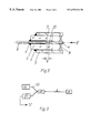
- FIGS. 1 a , 1 b , and 1 c depict a fiber optic pressure sensor
- FIG. 2 depicts another embodiment of a fiber optic pressure sensor
- FIG. 3 is a block diagram of a pressure sensor measurement system
- FIG. 4 is a view of a sensor interferometric response to pressure change ⁇ P;
- FIG. 5 is a view of calibration dependencies of the pressure sensor in analog and digital measurements
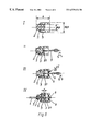
- FIG. 6 is a view of basic stages of the pressure sensor fabrication process.
- a fiber optic pressure sensor (FIG. 2) adapted to measure pressure with an enhanced sensitivity comprises a single-mode optical fiber 1 , a capillary 2 , a second capillary 3 , a flexible diaphragm 8 , a multi-mode optical fiber length 9 with a reflective end face 10 , epoxy splices 5 and a Fabry-Perot interferometer 6 formed by end faces 7 and 10 of the optical fibers 1 and 9 , respectively.
- the internal diameter of the capillary 2 is 20-30 ⁇ m greater than the external diameter of the multi-mode optical fiber length 9 , to allow a free longitudinal displacement of the optical fiber length 9 .
- Pasting-in the other end of the optical fiber length 9 to the center of the flexible polymer membrane 8 axisymmetrically with the pasted-in end of the single-mode optical fiber 7 makes possible the interferometer 6 for precision measurement of changes in the cavity length and, consequently, pressure P.
- a sensitive interference-protected optic fiber sensor designed in accordance with the invention for measuring a hydrostatic pressure within the range of from 0.5 to 1.5 atm has two measuring calibration scales: the analog scale with a sensitivity to about 0.01 atm, and the highly sensitive interferometer scale with the resolution and minimum sensitivity to about 10 ⁇ 4 atm.
- the use of the optical method of cavity length measurements and a laser source of probing light offers the improved sensitivity and enhances the temperature and vibration stability of the pressure sensor, as well as makes the sensor substantially completely immune to electromagnetic interference, the pressure measurement method being persistence-free.
- a pressure sensor (FIG. 2) is a low Q-factor Fabry-Perot cavity/interferometer 6 at the end of a single-mode optical fiber 1 with the 4% Fresnel reflection from the silica glass/air interface.
- the other movable mirror of the cavity is an end face 10 of a short (1 to 3 mm) optical fiber length 9 having a small inertial mass and pasted-in to the center of a flexible membrane 8 with a diameter of 500-700 ⁇ m which tightly seals a small air volume (about 1 to 3 mm 3 ) inside the second capillary 3 with an external diameter of 0.5-0.9 mm.
- End faces 7 and 10 of the optical fibers 1 and 9 forming the Fabry-Perot cavity 6 are located with about 50 ⁇ m gap inside the capillary 2 with an internal diameter of 145-170 ⁇ m.
- This allows the movable optical fiber length 9 arranged strictly in the center, to move longitudinally in a free, substantially frictionless fashion, thereby providing constant geometry and magnitude of the interferometer 6 response under mechanical vibrations in the transverse direction.
- the small inertial mass of the material of the flexible membrane 8 and the pasted-in short optical fiber length 9 provide the great stability of the structure against the inertial forces caused by accelerations in the longitudinal direction, while in the transverse direction the acceleration forces do not disrupt the geometry of the interferometer 6 and do not substantially affect the pressure sensor operation.
- the high thermal resistance of the quartz capillaries 2 and 3 (the linear expansion factor smaller than 10 ⁇ 6 l/° C.) and the small volume of air inside the capillaries lead to the enhanced stability of the sensor indications and calibrations under temperature changes. Calculations and experiments have demonstrated that the temperature stability value of the sensor in accordance with the invention is ⁇ P/ ⁇ T ⁇ 0.001 atm/° C.
- the cavity of the interferometer 6 is formed by shattered end faces 7 and 10 of the optical fibers 1 and 9 with the 4% Fresnel reflection provides the reproducibility of the sine wave interferometric response of the sensor in operation at the end of the long optical fiber 1 when the interferometer signal is generated by combining (interfering) a single-mode radiation reflected from the end face 7 of the optical fiber 1 which is a trunk fiber, with a light of the same geometry, but singly reflected from the end face 10 of the movable optical fiber length 9 and inputted back to the optical fiber 1 .
- the laser source 11 may be a laser module with an output fiber 12 .
- FIG. 3 also shows a directional X or Y-type coupler 13 to input the light of the laser source 11 to the single-mode optical fiber 1 and output the light to a light detector 14 , and the interferometer 6 of the pressure sensor.
- the pressure sensor measurement system (FIG.
- a laser excitation/modulation system (not shown), and, if required, an internal optical insulator, a pre-amplifier and a processing circuit (in simple case, a demodulator or a phase detector) with output to recording apparatuses (recorders, computers).
- the optical insulator may be necessary in the module since generally used in precision measurements are supermode lasers, the radiation spectrum of which may be distorted by the returned light due to the effects of the composite cavity.
- the sine waveform in the measurement system is generated in the light detector 14 where a photodiode (germanium, silicon or four-component photodiode) acts as a square-law detector of the total light field of two light fields reflected from the cavity faces.
- the measured pressure P is proportional to cavity length change ⁇ L, which, in turn, may be determined, at appropriate response calibration, from interferometric response phase change ⁇ :
- the above formula showing a simple (linear) relationship between the cavity length and the phase change, may be used for absolute pressure measurements upon establishing the proportionality factor or apparatus function in the course of calibration.
- Phase measurements of sine waveforms are well developed today, and metrologically precise instruments can be designed, with the proviso that a sufficient isolation is provided against spurious and other cognate physical effects (temperature, etc.).
- the pressure sensor in accordance with the invention (FIG. 2) allows designing such instruments owing to the small size and weight, and the absence of metal in the structure.
- the combination of the aforementioned qualitative and quantitative characteristics of the pressure sensors (FIG. 1 and 2) in accordance with the invention is not met in conventional sensor designs.
- the structure in accordance with the invention By modifying the flexibility, size and material of the membrane 8 , one may design sensors with the structure in accordance with the invention, which will have properties optimized for each application, e.g. for the measured pressure range from about 10 ⁇ 4 atm to 10-100 atm and greater.
- the latter lasers are preferable in those cases when strict requirements are imposed on the measured pressure resolution or when it is necessary to measure small absolute pressure values, which require precise maintenance and measurement of the sensor interference response phase in the measurement system.
- FIG. 4 shows a typical response of the pressure sensor (a response fragment is shown within ⁇ 0.1 atm of about 1 atm pressure).
- a response fragment is shown within ⁇ 0.1 atm of about 1 atm pressure.
- the dependence of the period number N on the pressure being substantially linear throughout the pressure variation range of from 0.5 to 1.5 atm (FIG. 5 ).
- the N( ⁇ P) relationship linearity (FIG.
- FIG. 4 also shows that the envelope of the sensor sine wave response forms a second calibration curve in the analog form (shown in FIG. 5 ), the appearance of which is related with the relationship between the efficiency of input of the light reflected from the movable end face 10 of the optical fiber 9 and the distance between the end faces 7 and 10 ; with increase in pressure, the end faces 7 and 10 approach, the interferometer 7 cavity becomes shorter and the interference signal amplitude increases.
- the increase in the oscillation amplitude is evidence that the pressure increases, and this fact may be used to establish the pressure change sign when operating in digital mode.
- the interferometer operating point may be selected at the center of the sine wave response (FIG. 4 ), in this case the sensor (FIG. 2) and the system (FIG.
- capillaries 2 and 3 having a length of 2-4 mm or 3-5 mm are spliced with an epoxy at points 5 with a 1-2 mm misalignment along the optical axis.
- This is a preform of a sensor housing.
- an end face 10 of a multi-mode optical fiber 9 is inserted into the first capillary 2 at a depth of from 0.5 to 1 mm, the end face 10 being centered, using an XYZ three-axis table, in the radial direction so that the optical fiber 9 does not contact the internal walls of the capillary 2 and is on the capillary axis.
- a small amount of a polymerizing liquid 15 is added on the side of the capillary 3 end face where the optical fiber 9 is inserted, to wet both the fiber 9 and the capillary 3 end face.
- excess of liquid 15 is removed using a dry fiber length or thin wire.
- the polymerizing liquid 15 Being drawn into the capillary 3 owing to good wettability of the silica glass of which the capillary 3 and the optical fiber 9 are made, the polymerizing liquid 15 forms meniscuses which automatically facilitate centering the optical fiber 9 inside the capillary 3 and form a flexible membrane 8 .
- the projecting end of the optical fiber 9 is cut.
- an end face 7 of a single-mode optical fiber 1 with the 4% Fresnel reflection from the end face 7 is inserted into the capillary 2 at a depth of about 0.5 mm.
- the optical fiber 1 is wetted with an epoxy at points 5 and inserted towards the multimode optical fiber 9 .
- a gap of about 30 to 300 ⁇ m between the end faces 7 and 10 of the optical fibers 1 and 9 is established on the basis of the expected pressure measurement range and the flexibility of the membrane 8 .
- the flexibility of the membrane 8 is varied within some limits by modifying its thickness in the fabrication process or by selecting an appropriate polymer. Reproducibility of the pressure sensor sensitivity (FIG.
- One more structural feature of the pressure sensor defines its speed of response. Owing to the fact that the movable optical fiber length 9 is inserted into the capillary 2 with the internal diameter which is only 20-30 ⁇ m greater than the external diameter (125 ⁇ m) of the optical fiber 9 , air damps the movement of the optical fiber 9 when it moves fast (the pump effect), this limiting the speed of its displacement. Measurements of the relationship between the sensor interferometric response and the external pressure change frequency have shown that the sensor frequency range is limited within the frequencies of about 600-700 Hz. As a consequence, the sensor (FIG. 2) should be considered as a comparatively low-frequency one and adapted to measure hydrostatic or slowly changing pressures. These abilities of the sensor may be advantageous when smooth pressure changes are accompanied by vortexes and turbulence, as well as high-frequency acoustic signals, which should be sensed by the sensor (FIG. 1 ).
- a single-mode optical fiber 1 was fixed in the capillary 2 so that its end face 7 projected at about 1 mm, and a diaphragm 4 from aluminum foil 10 ⁇ m thick was attached to the capillary 3 end face with an epoxy to tightly seal the internal volume of 1-2 mm 3 .
- the gap between the end face 7 of the single-mode optical fiber and the plane of the diaphragm 4 was increased to 100-200 ⁇ m in order to balance intensities of interfering signals at the light detector 14 (FIG. 3) and obtain a sine wave interferometric response without sacrifice to the optical efficiency of the sensor measurement system.
- the pressure sensor (FIG. 1) exhibits high-frequency characteristics and is capable of sensing the pressure changes having the upper frequency as high as 100 kHz.
- the dynamic range of the sensor (FIG. 1) is, apparently, still wider that that of the second variant of the sensor (FIG. 2) due to the greater original gap between the end face 7 of the single-mode optical fiber 1 and the diaphragm 4 .
- FIG. 2 Experimental data (FIGS. 4 and 5) has been obtained for the pressure sensor (FIG. 2) in which the silica glass capillary 3 had the length of 3 mm, the external diameter of 1 mm and the internal diameter of 0.7 mm.
- the silica glass capillary 2 had the length of 3 mm, the external diameter of 700 ⁇ m and the internal diameter of 145 ⁇ m.
- the capillary 2 was inserted into the second capillary 3 at a depth of from 1 to 2 mm.
- the external diameter of the optical fibers 1 and 9 was 125 ⁇ m.
- the optical fiber 9 was inserted into the capillary 2 at a depth of about 0.5 mm.
- the flexible membrane 8 was of an organosilicon polymer. Its thickness was about 0.3 to 0.5 mm in the narrow place.
- the distance between the end faces 7 and 10 of the optical fibers 1 and 9 was 50 ⁇ m.
- the optical fiber length 9 projected out from the membrane at 1 mm.
- Used as a radiation source 11 in the measurement system was a laser module with an output fiber 12 based on a supermode semiconductor DFB-laser with the 1.5 ⁇ m wavelength and the radiation bandwidth of ⁇ 10 ⁇ 4 nm.
- a directional Y-type coupler 13 To input the light of the laser source 11 to the single-mode optical fiber 1 and to output the light to the light detector 14 , the use was made of a directional Y-type coupler 13 .
- the light detector was a germanium photodiode of PD-10G type.
- the present invention is suitable for aerodynamic investigations of aircraft and small spacecraft, in robotics, including small force micro-clamps, in remote pressure monitoring (in wells, vessels, cylinders), in medicine and medical and biological investigations, hydroacoustics, security systems.
Abstract
Description
Claims (28)
Priority Applications (1)
| Application Number | Priority Date | Filing Date | Title |
|---|---|---|---|
| US10/354,191 US20030138185A1 (en) | 1998-06-16 | 2003-01-30 | Fiber-optic pressure sensor, variants and method for producing a resilient membrane |
Applications Claiming Priority (3)
| Application Number | Priority Date | Filing Date | Title |
|---|---|---|---|
| RU98111786 | 1998-06-16 | ||
| RU98111786/28A RU2152601C1 (en) | 1998-06-16 | 1998-06-16 | Fiber-optic pressure transducer (design versions) and its manufacturing process |
| PCT/RU1999/000086 WO1999066299A1 (en) | 1998-06-16 | 1999-03-24 | Fiber-optic pressure sensor, variants and method for producing a resilient membrane |
Related Parent Applications (1)
| Application Number | Title | Priority Date | Filing Date |
|---|---|---|---|
| PCT/RU1999/000086 A-371-Of-International WO1999066299A1 (en) | 1998-06-16 | 1999-03-24 | Fiber-optic pressure sensor, variants and method for producing a resilient membrane |
Related Child Applications (1)
| Application Number | Title | Priority Date | Filing Date |
|---|---|---|---|
| US10/354,191 Division US20030138185A1 (en) | 1998-06-16 | 2003-01-30 | Fiber-optic pressure sensor, variants and method for producing a resilient membrane |
Publications (1)
| Publication Number | Publication Date |
|---|---|
| US6539136B1 true US6539136B1 (en) | 2003-03-25 |
Family
ID=20207494
Family Applications (2)
| Application Number | Title | Priority Date | Filing Date |
|---|---|---|---|
| US09/719,834 Expired - Fee Related US6539136B1 (en) | 1998-06-16 | 1999-03-24 | Fiber-optic pressure sensor, variants and method for producing a resilient membrane |
| US10/354,191 Abandoned US20030138185A1 (en) | 1998-06-16 | 2003-01-30 | Fiber-optic pressure sensor, variants and method for producing a resilient membrane |
Family Applications After (1)
| Application Number | Title | Priority Date | Filing Date |
|---|---|---|---|
| US10/354,191 Abandoned US20030138185A1 (en) | 1998-06-16 | 2003-01-30 | Fiber-optic pressure sensor, variants and method for producing a resilient membrane |
Country Status (8)
| Country | Link |
|---|---|
| US (2) | US6539136B1 (en) |
| EP (1) | EP1089062A1 (en) |
| JP (1) | JP2002518667A (en) |
| KR (1) | KR20010071501A (en) |
| CN (1) | CN1309764A (en) |
| CA (1) | CA2335211A1 (en) |
| RU (1) | RU2152601C1 (en) |
| WO (1) | WO1999066299A1 (en) |
Cited By (54)
| Publication number | Priority date | Publication date | Assignee | Title |
|---|---|---|---|---|
| US20030039428A1 (en) * | 2000-09-20 | 2003-02-27 | Koji Okamoto | Optical fiber interferosensor, signal-processing system for optical fiber interferosensor and recording medium |
| US6618523B2 (en) * | 1997-06-06 | 2003-09-09 | Litton Systems, Inc. | Unbalanced fiber optic Michelson interferometer as an optical pick-off |
| US20040151417A1 (en) * | 2002-05-28 | 2004-08-05 | Nicholas Lagakos | Intensity modulated fiber optic pressure sensor |
| US20050041905A1 (en) * | 2003-05-28 | 2005-02-24 | Nicholas Lagakos | Fiber optic pressure sensor |
| US20050195402A1 (en) * | 2004-03-04 | 2005-09-08 | Russell May | Crystalline optical fiber sensors for harsh environments |
| US20050195403A1 (en) * | 2004-03-04 | 2005-09-08 | Juncheng Xu | Optical fiber sensors for harsh environments |
| US20050231729A1 (en) * | 2004-04-15 | 2005-10-20 | Lopushansky Richard L | Method and apparatus for continuous readout of Fabry-Perot fiber optic sensor |
| US20050230605A1 (en) * | 2004-04-20 | 2005-10-20 | Hamid Pishdadian | Method of measuring using a binary optical sensor |
| US20050244096A1 (en) * | 2004-04-15 | 2005-11-03 | Jeffers Larry A | Interferometric signal conditioner for measurement of absolute static displacements and dynamic displacements of a fabry-perot interferometer |
| US20050254062A1 (en) * | 2003-11-06 | 2005-11-17 | Fortebio, Inc. | Fiber-optic assay apparatus based on phase-shift interferometry |
| US20060072887A1 (en) * | 2002-05-28 | 2006-04-06 | Nicholas Lagakos | Intensity modulated fiber optic static pressure sensor system |
| US20060139652A1 (en) * | 2004-12-21 | 2006-06-29 | Berthold John W | Fiber optic sensor system |
| US20060154320A1 (en) * | 2005-01-07 | 2006-07-13 | Fortebio, Inc. | Enzyme activity measurement using bio-layer interferometry |
| WO2006092052A1 (en) * | 2005-03-02 | 2006-09-08 | Fiso Technologies Inc. | Fabry-perot optical sensor and method of manufacturing the same |
| US20060241889A1 (en) * | 2004-12-21 | 2006-10-26 | Lopushansky Richard L | Multi-channel array processor |
| WO2007019676A1 (en) | 2005-08-12 | 2007-02-22 | Fiso Technologies Inc. | Single piece fabry-perot optical sensor and method of manufacturing the same |
| US20070064241A1 (en) * | 2005-09-13 | 2007-03-22 | Needham David B | Tracking algorithm for linear array signal processor for fabry-perot cross-correlation pattern and method of using same |
| US20080043245A1 (en) * | 2006-08-16 | 2008-02-21 | Needham David B | Methods and apparatus for measuring multiple fabry-perot gaps |
| US20080144039A1 (en) * | 2003-11-06 | 2008-06-19 | Fortebio, Inc. | Fiber-Optic Assay Apparatus Based on Phase-Shift Interferometry |
| US20080186506A1 (en) * | 2007-01-24 | 2008-08-07 | Davidson Instruments, Inc. | Transducer for measuring environmental parameters |
| US20090056447A1 (en) * | 2006-04-26 | 2009-03-05 | Berthold John W | Fiber optic MEMS seismic sensor with mass supported by hinged beams |
| US20090202195A1 (en) * | 2008-02-11 | 2009-08-13 | Nicholas Lagakos | Fiber Optic Pressure Sensors and Catheters |
| US20090207417A1 (en) * | 2005-03-16 | 2009-08-20 | Halliburton Energy Services, Inc. | High Intensity Fabry-Perot Sensor |
| US20090252451A1 (en) * | 2008-04-03 | 2009-10-08 | The Government Of The Us, As Respresented By The Secretary Of The Navy | Intensity Modulated Fiber Optic Strain Sensor |
| US7684051B2 (en) | 2006-04-18 | 2010-03-23 | Halliburton Energy Services, Inc. | Fiber optic seismic sensor based on MEMS cantilever |
| US20100093106A1 (en) * | 2006-09-14 | 2010-04-15 | Fortebio, Inc. | Amine-Reactive Biosensor |
| US20100097600A1 (en) * | 2008-10-21 | 2010-04-22 | Mark William Barenek | Fiber Optic Optical Subassembly Configuration |
| CN101034028B (en) * | 2007-02-09 | 2010-05-19 | 南京师范大学 | Fabry-Perotw fiber-optic pressure sensor and manufacture method therefor |
| US20100233353A1 (en) * | 2009-03-16 | 2010-09-16 | Applied Materials, Inc. | Evaporator, coating installation, and method for use thereof |
| US20110007997A1 (en) * | 2009-07-07 | 2011-01-13 | Pierre Galarneau | Fiber-optic temperature sensor assembly |
| US20110044373A1 (en) * | 2009-08-19 | 2011-02-24 | The Government of the US, as represented by the Secretary fo the Navy | Miniature Fiber Optic Temperature Sensor with Edge Reflector |
| US7930934B2 (en) | 2008-06-06 | 2011-04-26 | Avl List Gmbh | Measuring device |
| US20110211940A1 (en) * | 2010-02-26 | 2011-09-01 | General Electric Company | System and method for inspection of stator vanes |
| US20110268384A1 (en) * | 2010-03-15 | 2011-11-03 | The Board Of Trustees Of The Leland Stanford Junior University | Optical-fiber-compatible acoustic sensor |
| EP2498049A1 (en) * | 2011-03-11 | 2012-09-12 | University of Maribor | Optical fiber sensors having long active lengths, systems, and methods |
| US8537368B2 (en) | 2006-05-04 | 2013-09-17 | The Board Of Trustees Of The Leland Stanford Junior University | Method of detecting an acceleration |
| US8548283B2 (en) | 2007-01-09 | 2013-10-01 | The Board Of Trustees Of The Leland Stanford Junior University | Optical system having a photonic crystal structure and method of fabrication |
| US8557129B2 (en) | 2011-03-11 | 2013-10-15 | University of Maribor | Methods of manufacturing optical devices |
| US8587660B2 (en) | 2010-07-30 | 2013-11-19 | General Electric Company | Image recording assemblies and coupling mechanisms for stator vane inspection |
| US8647588B2 (en) | 2005-06-13 | 2014-02-11 | Pall Corporation | Tip tray assembly for optical sensors |
| US8655123B2 (en) | 2011-03-11 | 2014-02-18 | University of Maribor | In-line optical fiber devices, optical systems, and methods |
| US20140246571A1 (en) * | 2012-08-17 | 2014-09-04 | Oracle International Corporation | Reflection-enhanced photo-detector |
| US9086331B2 (en) | 2012-10-23 | 2015-07-21 | The Boeing Company | Optical fiber coupled photonic crystal slab strain sensor system |
| CN105136358A (en) * | 2015-04-27 | 2015-12-09 | 清华大学 | Dual-Fabry-Perot fiber pressure sensor, measurement device and calculation method |
| US20160018280A1 (en) * | 2015-01-16 | 2016-01-21 | National Institute Of Standards And Technology | Photonic article, process for making and using same |
| CN106052913A (en) * | 2016-07-11 | 2016-10-26 | 中国计量大学 | Pressure sensing device with high sensitivity |
| CN110057479A (en) * | 2019-04-17 | 2019-07-26 | 中国地质大学(武汉) | Plating laminar double-layer sensitive film and preparation method for FP chamber fibre optic compression sensor |
| US20210164853A1 (en) * | 2019-11-29 | 2021-06-03 | Meggitt Sa | Optical sensor for the measurement of physical parameters in harsh environments and methods of making and using the same |
| CN113029428A (en) * | 2021-03-30 | 2021-06-25 | 武汉理工大学 | FP (Fabry-Perot) air pressure sensor based on gas-sensitive film in optical fiber and preparation method thereof |
| EP3904851A1 (en) * | 2020-04-21 | 2021-11-03 | Kidde Technologies, Inc. | Fabry-perot based advance pneumatic fire/overheat detector |
| CN113607332A (en) * | 2021-07-30 | 2021-11-05 | 深圳技术大学 | Manufacturing method of static pressure sensor |
| CN113701915A (en) * | 2021-09-03 | 2021-11-26 | 西安石油大学 | Preparation method of polymer-filled optical fiber temperature sensor embedded with air bubbles |
| US11215481B2 (en) | 2018-03-23 | 2022-01-04 | The Board Of Trustees Of The Leland Stanford Junior University | Diaphragm-based fiber acoustic sensor |
| US11821801B1 (en) | 2019-01-18 | 2023-11-21 | Stable Laser Systems, Inc. | Implementation of a dual Fabry-Perot photonic pressure sensor |
Families Citing this family (45)
| Publication number | Priority date | Publication date | Assignee | Title |
|---|---|---|---|---|
| US6425290B2 (en) | 2000-02-11 | 2002-07-30 | Rosemount Inc. | Oil-less differential pressure sensor |
| DE10225934B4 (en) * | 2002-06-11 | 2010-08-19 | Robert Bosch Gmbh | Fiber optic pressure sensor |
| US7241986B2 (en) * | 2003-10-08 | 2007-07-10 | Mississippi State University | Fiber ringdown pressure/force sensors |
| US7136550B2 (en) | 2004-10-28 | 2006-11-14 | Corning Incorporated | Single-fiber launch/receive system for biosensing applications |
| DE102005018511A1 (en) * | 2005-04-20 | 2006-11-02 | Albert-Ludwigs-Universität Freiburg | Micromirror device, e.g. for micro-optical bank, has micromirror connected with translucent elastomer membrane, where mirror is pressure actuated and angle or translational position of mirror is varied |
| KR100746139B1 (en) * | 2005-05-21 | 2007-08-03 | 주식회사 아이세스 | Fiber-optic displacement measurement sensor device using cantilever |
| CN100507484C (en) * | 2005-09-20 | 2009-07-01 | 山东省科学院激光研究所 | High-performance optical fiber pressure sensor |
| WO2009079803A1 (en) * | 2007-12-20 | 2009-07-02 | Inficon Gmbh | Arrangement for a diaphragm pressure-measuring cell |
| US9528893B2 (en) | 2009-06-29 | 2016-12-27 | University Of Massachusetts | Optical fiber pressure sensor with uniform diaphragm and method of fabricating same |
| CN101832832B (en) * | 2010-05-28 | 2012-02-22 | 天津大学 | Optical fiber Fabry-Perot pressure sensor and production method thereof |
| CN101858809B (en) * | 2010-05-28 | 2012-03-21 | 天津大学 | Optical fiber Fabry-Perot pressure sensor and fabrication method thereof |
| US9587976B2 (en) | 2011-02-17 | 2017-03-07 | University Of Massachusetts | Photoacoustic probe |
| DE102011077499A1 (en) * | 2011-06-14 | 2012-12-20 | CiS Forschungsinstitut für Mikrosensorik und Photovoltaik GmbH | Interferometric pressure measuring cell |
| CN102879136B (en) * | 2011-07-11 | 2014-08-06 | 广东海洋大学 | Chitosan film high performance optical fiber pressure sensing head and manufacturing method of chitosan film high performance optical fiber pressure sensing head |
| CN102519663B (en) * | 2011-12-08 | 2013-10-02 | 武汉理工大学 | Polymer film optical fiber F-P cavity-based underwater shock pressure sensor and dynamic calibration experiment system thereof |
| CN103162878B (en) * | 2011-12-11 | 2015-12-09 | 黄辉 | A kind of fibre optic compression sensor and preparation method thereof |
| RU2509994C1 (en) * | 2012-07-17 | 2014-03-20 | Научная организация "Центр лазерной технологии и материаловедения" (Автономная некоммерческая организация) | Fibre-optic device of pressure measurement |
| KR101381954B1 (en) * | 2012-09-07 | 2014-04-07 | 한국광기술원 | Fabry-Perot interferometric fiber optic sensor system using ferrule and method of manufacturing the sensor |
| ITMI20130138A1 (en) * | 2013-01-31 | 2014-08-01 | Laser Point S R L | OPTICAL SENSOR FOR PRESSURE MEASURES WITHOUT CONTACT. |
| KR101439463B1 (en) * | 2013-03-21 | 2014-09-17 | 전진홍 | System for detecting pressure |
| RU2559312C1 (en) * | 2014-05-08 | 2015-08-10 | Федеральное государственное унитарное предприятие "Всероссийский научно-исследовательский институт автоматики им. Н.Л. Духова" (ФГУП "ВНИИА") | Converter of mechanical values to optical signal |
| CN103994851B (en) * | 2014-05-15 | 2017-02-08 | 香港理工大学深圳研究院 | Resonant type Fabry-Perot optical fiber sensor, manufacturing method and air pressure detecting method |
| CN104374515B (en) * | 2014-11-21 | 2016-05-25 | 贵州大学 | The arrangement of fibre bundle in a kind of reflection-type optical fiber pressure sensor probe |
| CN104596435B (en) * | 2014-12-04 | 2017-09-19 | 中国科学院上海微系统与信息技术研究所 | A kind of long adjustable optic fibre F P strain gauges of chamber based on MEMS technology and forming method |
| CN105841877B (en) * | 2015-01-13 | 2018-10-30 | 中国科学院理化技术研究所 | A kind of pressure detection method, device |
| CN106287223A (en) * | 2016-07-19 | 2017-01-04 | 昆山雅宝信息科技有限公司 | LNG gas station metering device based on optical fiber F P cavity pressure sensor |
| US10444063B2 (en) * | 2016-09-23 | 2019-10-15 | Baker Hughes, A Ge Company, Llc | Downhole fiber optic hydrophone |
| WO2018084711A2 (en) * | 2016-11-07 | 2018-05-11 | Paul Johan Willem Maria Nooijen | Combustion pressure sensor and its assembly in an engine component of an internal combustion engine |
| CN106595730A (en) * | 2016-12-13 | 2017-04-26 | 哈尔滨工业大学(威海) | Method for preparing optical fiber end face liquid microcavity |
| GB2567610B (en) * | 2017-03-21 | 2021-07-21 | Nuron Ltd | Optical fibre pressure sensing apparatus employing longitudinal diaphragm |
| CN106996797B (en) * | 2017-05-02 | 2018-07-27 | 中国电子科技集团公司第四十九研究所 | A kind of optical fiber sensing probe |
| CN107484071B (en) * | 2017-09-13 | 2019-12-03 | 京东方科技集团股份有限公司 | A kind of optical fiber sound pick-up and preparation method thereof and preparation facilities |
| RU2675411C1 (en) * | 2017-09-14 | 2018-12-19 | Российская Федерация, от имени которой выступает ФОНД ПЕРСПЕКТИВНЫХ ИССЛЕДОВАНИЙ | Design of high-strength sensors |
| WO2019189970A1 (en) * | 2018-03-30 | 2019-10-03 | 주식회사 씨엠랩 | Blood flow measuring apparatus and method having function of correcting noise due to pressure |
| CN108759983B (en) * | 2018-06-13 | 2020-04-24 | 天津大学 | Open cavity differential pressure type optical fiber Fabry-Perot liquid level sensor and liquid level measuring method thereof |
| CN109231161B (en) * | 2018-09-30 | 2020-06-16 | 重庆大学 | Method for manufacturing self-sensing micro clamp with clamping jaw being optical fiber Fabry-Perot interferometer |
| EP3673796A1 (en) * | 2018-12-31 | 2020-07-01 | SDS Optic Spolka Akcyjna | Use of a flexible capillary for the sensor detecting biologically active molecules |
| EP3674692A1 (en) * | 2018-12-31 | 2020-07-01 | SDS Optic Spolka Akcyjna | Device for the detection of biologically active molecules |
| CN110749370A (en) * | 2019-10-28 | 2020-02-04 | 中国科学院西安光学精密机械研究所 | Vibration sensor based on polymer optical fiber microcavity and polymer optical fiber film |
| CN111112035B (en) * | 2019-12-25 | 2021-02-09 | 华中科技大学 | Transmit-receive integrated all-optical ultrasonic transducer device and preparation method thereof |
| CN112284585B (en) * | 2020-10-16 | 2022-03-08 | 广州特种机电设备检测研究院 | Device based on optical fiber testing wheel pressure |
| CN113514165A (en) * | 2021-04-12 | 2021-10-19 | 武汉工程大学 | Device for simultaneously measuring curvature and temperature of optical fiber based on anti-resonance and multimode interference |
| CN113375844B (en) * | 2021-05-28 | 2023-06-16 | 北京航空航天大学 | FP pressure sensor based on photonic crystal fiber low-temperature coupling effect |
| CN113340491B (en) * | 2021-07-07 | 2024-01-05 | 中北大学 | Optical fiber Fabry-Perot pressure sensor and high-consistency preparation method of sensitive unit thereof |
| CN114414134B (en) * | 2022-01-21 | 2022-11-29 | 吉林大学 | Optical fiber hydraulic sensor based on PDMS membrane and vernier effect sensitization |
Citations (3)
| Publication number | Priority date | Publication date | Assignee | Title |
|---|---|---|---|---|
| DE3611852A1 (en) | 1985-04-11 | 1986-10-16 | Sharp K.K., Osaka | PRESSURE SENSITIVE ELEMENT |
| SU1571449A1 (en) | 1988-02-11 | 1990-06-15 | Научно-исследовательский институт энергетики и автоматики АН УзССР | Fiber-optic pressure transducer |
| SU1686321A1 (en) | 1989-04-13 | 1991-10-23 | Хозрасчетный Центр Научно-Технических Услуг "Випо" Ан Ссср | Device for measuring sound pressure |
-
1998
- 1998-06-16 RU RU98111786/28A patent/RU2152601C1/en not_active IP Right Cessation
-
1999
- 1999-03-24 US US09/719,834 patent/US6539136B1/en not_active Expired - Fee Related
- 1999-03-24 CN CN99808651A patent/CN1309764A/en active Pending
- 1999-03-24 EP EP99914822A patent/EP1089062A1/en not_active Withdrawn
- 1999-03-24 CA CA002335211A patent/CA2335211A1/en not_active Abandoned
- 1999-03-24 JP JP2000555068A patent/JP2002518667A/en active Pending
- 1999-03-24 KR KR1020007014327A patent/KR20010071501A/en not_active Application Discontinuation
- 1999-03-24 WO PCT/RU1999/000086 patent/WO1999066299A1/en not_active Application Discontinuation
-
2003
- 2003-01-30 US US10/354,191 patent/US20030138185A1/en not_active Abandoned
Patent Citations (3)
| Publication number | Priority date | Publication date | Assignee | Title |
|---|---|---|---|---|
| DE3611852A1 (en) | 1985-04-11 | 1986-10-16 | Sharp K.K., Osaka | PRESSURE SENSITIVE ELEMENT |
| SU1571449A1 (en) | 1988-02-11 | 1990-06-15 | Научно-исследовательский институт энергетики и автоматики АН УзССР | Fiber-optic pressure transducer |
| SU1686321A1 (en) | 1989-04-13 | 1991-10-23 | Хозрасчетный Центр Научно-Технических Услуг "Випо" Ан Ссср | Device for measuring sound pressure |
Non-Patent Citations (2)
| Title |
|---|
| "Diaphragm size and sensitivity for fiber optic pressure sensors", Gang He, et al., SPIE Fiber Optic and Laser Sensors, IX (1991, vol. 1584, pp. 152-156 No Date. |
| "Extrinsic Fabry-Perot Optical Fiber Sensor", Kent A. Murphy, et al., 8th Optical Fiber Sensors Conference, Jan. 29-31, 1992, Monterey Marriot, CA, pp. 193-196, No Date. |
Cited By (100)
| Publication number | Priority date | Publication date | Assignee | Title |
|---|---|---|---|---|
| US6618523B2 (en) * | 1997-06-06 | 2003-09-09 | Litton Systems, Inc. | Unbalanced fiber optic Michelson interferometer as an optical pick-off |
| US20030039428A1 (en) * | 2000-09-20 | 2003-02-27 | Koji Okamoto | Optical fiber interferosensor, signal-processing system for optical fiber interferosensor and recording medium |
| US7043102B2 (en) * | 2000-09-20 | 2006-05-09 | Kyowa Electronic Instruments Co., Ltd. | Optical fiber interferosensor, signal-processing system for optical fiber interferosensor and recording medium |
| US7020354B2 (en) * | 2002-05-28 | 2006-03-28 | The United States Of America As Represented By The Secretary Of The Navy | Intensity modulated fiber optic pressure sensor |
| US20040151417A1 (en) * | 2002-05-28 | 2004-08-05 | Nicholas Lagakos | Intensity modulated fiber optic pressure sensor |
| US20060072887A1 (en) * | 2002-05-28 | 2006-04-06 | Nicholas Lagakos | Intensity modulated fiber optic static pressure sensor system |
| US7460740B2 (en) | 2002-05-28 | 2008-12-02 | United States Of America As Represented By The Secretary Of The Navy | Intensity modulated fiber optic static pressure sensor system |
| US20050041905A1 (en) * | 2003-05-28 | 2005-02-24 | Nicholas Lagakos | Fiber optic pressure sensor |
| US7149374B2 (en) | 2003-05-28 | 2006-12-12 | The United States Of America As Represented By The Secretary Of The Navy | Fiber optic pressure sensor |
| US20050254062A1 (en) * | 2003-11-06 | 2005-11-17 | Fortebio, Inc. | Fiber-optic assay apparatus based on phase-shift interferometry |
| US7394547B2 (en) | 2003-11-06 | 2008-07-01 | Fortebio, Inc. | Fiber-optic assay apparatus based on phase-shift interferometry |
| US20080186505A1 (en) * | 2003-11-06 | 2008-08-07 | Fortebio, Inc. | Fiber-optic assay apparatus based on phase-shift interferometry |
| US20080144039A1 (en) * | 2003-11-06 | 2008-06-19 | Fortebio, Inc. | Fiber-Optic Assay Apparatus Based on Phase-Shift Interferometry |
| US7656536B2 (en) | 2003-11-06 | 2010-02-02 | Fortebio, Inc. | Fiber-optic assay apparatus based on phase-shift interferometry |
| US7728982B2 (en) | 2003-11-06 | 2010-06-01 | Fortebio, Inc. | Fiber-optic assay apparatus based on phase-shift interferometry |
| US20070013914A1 (en) * | 2004-03-04 | 2007-01-18 | Prime Research, Lc | Crystalline optical fiber sensors for harsh environments |
| US7173713B2 (en) | 2004-03-04 | 2007-02-06 | Virginia Tech Intellectual Properties, Inc. | Optical fiber sensors for harsh environments |
| US20050195403A1 (en) * | 2004-03-04 | 2005-09-08 | Juncheng Xu | Optical fiber sensors for harsh environments |
| US20050195402A1 (en) * | 2004-03-04 | 2005-09-08 | Russell May | Crystalline optical fiber sensors for harsh environments |
| US7940400B2 (en) | 2004-04-15 | 2011-05-10 | Halliburton Energy Services Inc. | Method and apparatus for continuous readout of fabry-perot fiber optic sensor |
| US20050244096A1 (en) * | 2004-04-15 | 2005-11-03 | Jeffers Larry A | Interferometric signal conditioner for measurement of absolute static displacements and dynamic displacements of a fabry-perot interferometer |
| US7492463B2 (en) | 2004-04-15 | 2009-02-17 | Davidson Instruments Inc. | Method and apparatus for continuous readout of Fabry-Perot fiber optic sensor |
| US20050231729A1 (en) * | 2004-04-15 | 2005-10-20 | Lopushansky Richard L | Method and apparatus for continuous readout of Fabry-Perot fiber optic sensor |
| US7305158B2 (en) | 2004-04-15 | 2007-12-04 | Davidson Instruments Inc. | Interferometric signal conditioner for measurement of absolute static displacements and dynamic displacements of a Fabry-Perot interferometer |
| US20050230605A1 (en) * | 2004-04-20 | 2005-10-20 | Hamid Pishdadian | Method of measuring using a binary optical sensor |
| US7864329B2 (en) | 2004-12-21 | 2011-01-04 | Halliburton Energy Services, Inc. | Fiber optic sensor system having circulators, Bragg gratings and couplers |
| US20060139652A1 (en) * | 2004-12-21 | 2006-06-29 | Berthold John W | Fiber optic sensor system |
| US7835598B2 (en) | 2004-12-21 | 2010-11-16 | Halliburton Energy Services, Inc. | Multi-channel array processor |
| US20060241889A1 (en) * | 2004-12-21 | 2006-10-26 | Lopushansky Richard L | Multi-channel array processor |
| US7445887B2 (en) | 2005-01-07 | 2008-11-04 | Fortebio, Inc. | Enzyme activity measurements using bio-layer interferometry |
| US20060154320A1 (en) * | 2005-01-07 | 2006-07-13 | Fortebio, Inc. | Enzyme activity measurement using bio-layer interferometry |
| US20080159687A1 (en) * | 2005-03-02 | 2008-07-03 | Denis Donlagic | Fabry-Perot Optical Sensor and Method of Manufacturing the Same |
| US8559770B2 (en) | 2005-03-02 | 2013-10-15 | Fiso Technologies Inc. | Fabry-perot optical sensor and method of manufacturing the same |
| WO2006092052A1 (en) * | 2005-03-02 | 2006-09-08 | Fiso Technologies Inc. | Fabry-perot optical sensor and method of manufacturing the same |
| US20090207417A1 (en) * | 2005-03-16 | 2009-08-20 | Halliburton Energy Services, Inc. | High Intensity Fabry-Perot Sensor |
| US7782465B2 (en) | 2005-03-16 | 2010-08-24 | Halliburton Energy Services, Inc. | High intensity fabry-perot sensor |
| US8647588B2 (en) | 2005-06-13 | 2014-02-11 | Pall Corporation | Tip tray assembly for optical sensors |
| WO2007019676A1 (en) | 2005-08-12 | 2007-02-22 | Fiso Technologies Inc. | Single piece fabry-perot optical sensor and method of manufacturing the same |
| US20070064241A1 (en) * | 2005-09-13 | 2007-03-22 | Needham David B | Tracking algorithm for linear array signal processor for fabry-perot cross-correlation pattern and method of using same |
| US7684051B2 (en) | 2006-04-18 | 2010-03-23 | Halliburton Energy Services, Inc. | Fiber optic seismic sensor based on MEMS cantilever |
| US20090056447A1 (en) * | 2006-04-26 | 2009-03-05 | Berthold John W | Fiber optic MEMS seismic sensor with mass supported by hinged beams |
| US7743661B2 (en) | 2006-04-26 | 2010-06-29 | Halliburton Energy Services, Inc. | Fiber optic MEMS seismic sensor with mass supported by hinged beams |
| US8537368B2 (en) | 2006-05-04 | 2013-09-17 | The Board Of Trustees Of The Leland Stanford Junior University | Method of detecting an acceleration |
| US8115937B2 (en) | 2006-08-16 | 2012-02-14 | Davidson Instruments | Methods and apparatus for measuring multiple Fabry-Perot gaps |
| US20080043245A1 (en) * | 2006-08-16 | 2008-02-21 | Needham David B | Methods and apparatus for measuring multiple fabry-perot gaps |
| US20100093106A1 (en) * | 2006-09-14 | 2010-04-15 | Fortebio, Inc. | Amine-Reactive Biosensor |
| US8548283B2 (en) | 2007-01-09 | 2013-10-01 | The Board Of Trustees Of The Leland Stanford Junior University | Optical system having a photonic crystal structure and method of fabrication |
| US7787128B2 (en) | 2007-01-24 | 2010-08-31 | Halliburton Energy Services, Inc. | Transducer for measuring environmental parameters |
| US20080186506A1 (en) * | 2007-01-24 | 2008-08-07 | Davidson Instruments, Inc. | Transducer for measuring environmental parameters |
| CN101034028B (en) * | 2007-02-09 | 2010-05-19 | 南京师范大学 | Fabry-Perotw fiber-optic pressure sensor and manufacture method therefor |
| US7697798B2 (en) | 2008-02-11 | 2010-04-13 | The United States Of America As Represented By The Secretary Of The Navy | Fiber optic pressure sensors and catheters |
| US20090202195A1 (en) * | 2008-02-11 | 2009-08-13 | Nicholas Lagakos | Fiber Optic Pressure Sensors and Catheters |
| US20090252451A1 (en) * | 2008-04-03 | 2009-10-08 | The Government Of The Us, As Respresented By The Secretary Of The Navy | Intensity Modulated Fiber Optic Strain Sensor |
| US7646946B2 (en) | 2008-04-03 | 2010-01-12 | The United States Of America As Represented By The Secretary Of The Navy | Intensity modulated fiber optic strain sensor |
| US7930934B2 (en) | 2008-06-06 | 2011-04-26 | Avl List Gmbh | Measuring device |
| US7714991B1 (en) * | 2008-10-21 | 2010-05-11 | The United States Of America As Represented By The Secretary Of The Navy | Fiber optic optical subassembly configuration |
| US20100097600A1 (en) * | 2008-10-21 | 2010-04-22 | Mark William Barenek | Fiber Optic Optical Subassembly Configuration |
| US20100233353A1 (en) * | 2009-03-16 | 2010-09-16 | Applied Materials, Inc. | Evaporator, coating installation, and method for use thereof |
| US20110007997A1 (en) * | 2009-07-07 | 2011-01-13 | Pierre Galarneau | Fiber-optic temperature sensor assembly |
| US8170382B2 (en) * | 2009-07-07 | 2012-05-01 | Institut National D'optique | Fiber-optic temperature sensor assembly |
| US8322919B2 (en) | 2009-08-19 | 2012-12-04 | The United States Of America, As Represented By The Secretary Of The Navy | Miniature fiber optic temperature sensor with edge reflector |
| US8195013B2 (en) | 2009-08-19 | 2012-06-05 | The United States Of America, As Represented By The Secretary Of The Navy | Miniature fiber optic temperature sensors |
| US20110044575A1 (en) * | 2009-08-19 | 2011-02-24 | The Government Of The Us, As Represented By The Secretary Of The Navy | Miniature Fiber Optic Temperature Sensors |
| US20110044373A1 (en) * | 2009-08-19 | 2011-02-24 | The Government of the US, as represented by the Secretary fo the Navy | Miniature Fiber Optic Temperature Sensor with Edge Reflector |
| US20110211940A1 (en) * | 2010-02-26 | 2011-09-01 | General Electric Company | System and method for inspection of stator vanes |
| US8602722B2 (en) | 2010-02-26 | 2013-12-10 | General Electric Company | System and method for inspection of stator vanes |
| US8897610B2 (en) * | 2010-03-15 | 2014-11-25 | The Board Of Trustees Of The Leland Stanford Junior University | Method of fabricating an optical-fiber-compatible sensor |
| US20110268384A1 (en) * | 2010-03-15 | 2011-11-03 | The Board Of Trustees Of The Leland Stanford Junior University | Optical-fiber-compatible acoustic sensor |
| US8542956B2 (en) * | 2010-03-15 | 2013-09-24 | The Board Of Trustees Of The Leland Stanford Junior University | Optical-fiber-compatible acoustic sensor |
| US20150330830A1 (en) * | 2010-03-15 | 2015-11-19 | The Board Of Trustees Of The Leland Stanford Junior University | Optical-fiber-compatible sensor |
| US9702755B2 (en) * | 2010-03-15 | 2017-07-11 | The Board Of Trustees Of The Leland Stanford Junior University | Optical-fiber-compatible sensor |
| US8587660B2 (en) | 2010-07-30 | 2013-11-19 | General Electric Company | Image recording assemblies and coupling mechanisms for stator vane inspection |
| US8655117B2 (en) | 2011-03-11 | 2014-02-18 | University of Maribor | Optical fiber sensors having long active lengths, systems, and methods |
| US8655123B2 (en) | 2011-03-11 | 2014-02-18 | University of Maribor | In-line optical fiber devices, optical systems, and methods |
| US9139468B2 (en) | 2011-03-11 | 2015-09-22 | University of Maribor | Optical fiber sensors having long active lengths, systems, and methods |
| US8557129B2 (en) | 2011-03-11 | 2013-10-15 | University of Maribor | Methods of manufacturing optical devices |
| EP2498049A1 (en) * | 2011-03-11 | 2012-09-12 | University of Maribor | Optical fiber sensors having long active lengths, systems, and methods |
| US20140246571A1 (en) * | 2012-08-17 | 2014-09-04 | Oracle International Corporation | Reflection-enhanced photo-detector |
| US10119857B2 (en) * | 2012-08-17 | 2018-11-06 | Oracle International Corporation | Reflection-enhanced photo-detector |
| US9086331B2 (en) | 2012-10-23 | 2015-07-21 | The Boeing Company | Optical fiber coupled photonic crystal slab strain sensor system |
| US9347841B2 (en) | 2012-10-23 | 2016-05-24 | The Boeing Company | Optical fiber coupled photonic crystal slab strain sensor, system and method of fabrication and use |
| US9921115B2 (en) | 2012-10-23 | 2018-03-20 | The Boeing Company | Optical fiber coupled photonic crystal slab strain sensor, system and method of fabrication and use |
| US20160018280A1 (en) * | 2015-01-16 | 2016-01-21 | National Institute Of Standards And Technology | Photonic article, process for making and using same |
| US9719878B2 (en) * | 2015-01-16 | 2017-08-01 | The United States Of America, As Represented By The Secretary Of Commerce | Photonic article, process for making and using same |
| CN105136358B (en) * | 2015-04-27 | 2017-10-17 | 清华大学 | A kind of double method amber pressure sensors of optical fiber, measurement apparatus and computational methods |
| CN105136358A (en) * | 2015-04-27 | 2015-12-09 | 清华大学 | Dual-Fabry-Perot fiber pressure sensor, measurement device and calculation method |
| CN106052913A (en) * | 2016-07-11 | 2016-10-26 | 中国计量大学 | Pressure sensing device with high sensitivity |
| CN106052913B (en) * | 2016-07-11 | 2024-02-20 | 中国计量大学 | High-sensitivity pressure sensing device |
| US11215481B2 (en) | 2018-03-23 | 2022-01-04 | The Board Of Trustees Of The Leland Stanford Junior University | Diaphragm-based fiber acoustic sensor |
| US11629979B2 (en) | 2018-03-23 | 2023-04-18 | The Board Of Trustees Of The Leland Stanford Junior University | Diaphragm-based fiber acoustic sensor |
| US11821801B1 (en) | 2019-01-18 | 2023-11-21 | Stable Laser Systems, Inc. | Implementation of a dual Fabry-Perot photonic pressure sensor |
| CN110057479A (en) * | 2019-04-17 | 2019-07-26 | 中国地质大学(武汉) | Plating laminar double-layer sensitive film and preparation method for FP chamber fibre optic compression sensor |
| CN110057479B (en) * | 2019-04-17 | 2023-09-22 | 中国地质大学(武汉) | Coating type double-layer sensitive film for FP cavity optical fiber pressure sensor and preparation method |
| US20210164853A1 (en) * | 2019-11-29 | 2021-06-03 | Meggitt Sa | Optical sensor for the measurement of physical parameters in harsh environments and methods of making and using the same |
| EP3904851A1 (en) * | 2020-04-21 | 2021-11-03 | Kidde Technologies, Inc. | Fabry-perot based advance pneumatic fire/overheat detector |
| CN113029428B (en) * | 2021-03-30 | 2022-07-08 | 武汉理工大学 | FP (Fabry-Perot) air pressure sensor based on gas-sensitive film in optical fiber and preparation method thereof |
| CN113029428A (en) * | 2021-03-30 | 2021-06-25 | 武汉理工大学 | FP (Fabry-Perot) air pressure sensor based on gas-sensitive film in optical fiber and preparation method thereof |
| CN113607332A (en) * | 2021-07-30 | 2021-11-05 | 深圳技术大学 | Manufacturing method of static pressure sensor |
| CN113701915A (en) * | 2021-09-03 | 2021-11-26 | 西安石油大学 | Preparation method of polymer-filled optical fiber temperature sensor embedded with air bubbles |
| CN113701915B (en) * | 2021-09-03 | 2023-06-23 | 西安石油大学 | Preparation method of polymer filled optical fiber temperature sensor embedded with air bubbles |
Also Published As
| Publication number | Publication date |
|---|---|
| KR20010071501A (en) | 2001-07-28 |
| CN1309764A (en) | 2001-08-22 |
| CA2335211A1 (en) | 1999-12-23 |
| JP2002518667A (en) | 2002-06-25 |
| RU2152601C1 (en) | 2000-07-10 |
| EP1089062A1 (en) | 2001-04-04 |
| US20030138185A1 (en) | 2003-07-24 |
| WO1999066299A1 (en) | 1999-12-23 |
Similar Documents
| Publication | Publication Date | Title |
|---|---|---|
| US6539136B1 (en) | Fiber-optic pressure sensor, variants and method for producing a resilient membrane | |
| US6281976B1 (en) | Fiber optic fiber Fabry-Perot interferometer diaphragm sensor and method of measurement | |
| CA2537214C (en) | Optical fiber pressure and acceleration sensor fabricated on a fiber endface | |
| US6671055B1 (en) | Interferometric sensors utilizing bulk sensing mediums extrinsic to the input/output optical fiber | |
| Fender et al. | Two-axis temperature-insensitive accelerometer based on multicore fiber Bragg gratings | |
| Pang et al. | MEMS Fabry-Perot sensor interrogated by optical system-on-a-chip for simultaneous pressure and temperature sensing | |
| EP3163276A2 (en) | Fabry-perot optical sensor | |
| JPH0130081B2 (en) | ||
| Zhu et al. | Advances in fiber-optic extrinsic Fabry-Perot interferometric physical and mechanical sensors: a review | |
| Vorathin et al. | FBG water-level transducer based on PVC-cantilever and rubber-diaphragm structure | |
| Wu et al. | Single-crystal silicon photonic-crystal fiber-tip pressure sensors | |
| Bae et al. | Miniature temperature compensated Fabry–Perot pressure sensors created with self-aligned polymer photolithography process | |
| Xu | High temperature high bandwidth fiber optic pressure sensors | |
| Jansen et al. | High pressure fiber-optic sensor with side-hole fiber | |
| Wong et al. | Design and fabrication of monolithic photonic crystal fiber acoustic sensor | |
| Fang et al. | MEMS fiber-optic Fabry-Perot pressure sensor for high temperature application | |
| Lai et al. | Study on optical fiber pressure sensors with temperature-insensitivity based on Fabry-Pérot interferometry | |
| US11835406B2 (en) | Optical fiber sensing device having a symmetric optical fiber arrangement | |
| Hong et al. | Low-cost fiber optic cantilever accelerometer with a spherical tip based on gaussian beam focusing | |
| Mahissi et al. | Diaphragms simulation, fabrication, and testing of a high temperature fiber optic FP accelerometer based on MEMS | |
| Wang et al. | All-optical accelerometer based on micromachined silicon wafer | |
| Jonsson et al. | Multimode fiber-optic accelerometers | |
| Mishra et al. | Finite element analysis and experimental validation of suppression of span in optical MEMS pressure sensors | |
| EP0446349A1 (en) | Method for eliminating the temperature sensitivity of an optical fiber and a temperature insensitive optical fiber | |
| Demagh et al. | Optimization of a temperature and pressure fibre optic sensor based on a deformable micromirror |
Legal Events
| Date | Code | Title | Description |
|---|---|---|---|
| AS | Assignment |
Owner name: NAUCHNY TSENTR VOLOKONNOI OPTIKI PRI INSTITUTE OBS Free format text: ASSIGNMENT OF ASSIGNORS INTEREST;ASSIGNORS:DIANOV, EVGENY MIKHAILOVICH;BELOVOLOV, MIKHAIL IVANOVICH;BUBNOV, MIKHAIL MIKHAILOVICH;AND OTHERS;REEL/FRAME:011465/0853 Effective date: 20001208 |
|
| AS | Assignment |
Owner name: NAUCHNY TSENTR VOLOKONNOI OPTIKI PRI INSTITUTE OBS Free format text: RE-RECORD TO CORRECT THE NAME OF THE ASSIGNEE, PREVIOUSLY RECORDED ON REEL 011465 FRAME 0853, ASSIGNOR CONFIRMS THE ASSIGNMENT OF THE ENTIRE INTEREST.;ASSIGNORS:DIANOV, EVGENY MIKHAILOVICH;BELOVOLOV, MIKHAIL IVANOVICH;BUBNOV, MIKHAIL MIKHAILOVICH;AND OTHERS;REEL/FRAME:011744/0773 Effective date: 20001208 |
|
| CC | Certificate of correction | ||
| FPAY | Fee payment |
Year of fee payment: 4 |
|
| FEPP | Fee payment procedure |
Free format text: PAYER NUMBER DE-ASSIGNED (ORIGINAL EVENT CODE: RMPN); ENTITY STATUS OF PATENT OWNER: SMALL ENTITY Free format text: PAYOR NUMBER ASSIGNED (ORIGINAL EVENT CODE: ASPN); ENTITY STATUS OF PATENT OWNER: SMALL ENTITY |
|
| FPAY | Fee payment |
Year of fee payment: 8 |
|
| REMI | Maintenance fee reminder mailed | ||
| LAPS | Lapse for failure to pay maintenance fees | ||
| STCH | Information on status: patent discontinuation |
Free format text: PATENT EXPIRED DUE TO NONPAYMENT OF MAINTENANCE FEES UNDER 37 CFR 1.362 |
|
| FP | Lapsed due to failure to pay maintenance fee |
Effective date: 20150325 |