US6537005B1 - Blind fastener - Google Patents
Blind fastener Download PDFInfo
- Publication number
- US6537005B1 US6537005B1 US09/831,857 US83185701A US6537005B1 US 6537005 B1 US6537005 B1 US 6537005B1 US 83185701 A US83185701 A US 83185701A US 6537005 B1 US6537005 B1 US 6537005B1
- Authority
- US
- United States
- Prior art keywords
- sleeve
- abutment member
- head
- workpiece
- pin
- Prior art date
- Legal status (The legal status is an assumption and is not a legal conclusion. Google has not performed a legal analysis and makes no representation as to the accuracy of the status listed.)
- Expired - Lifetime
Links
- 230000006835 compression Effects 0.000 claims description 24
- 238000007906 compression Methods 0.000 claims description 24
- 238000000034 method Methods 0.000 claims description 5
- 238000003780 insertion Methods 0.000 claims 1
- 230000037431 insertion Effects 0.000 claims 1
- 238000009434 installation Methods 0.000 description 4
- 239000000463 material Substances 0.000 description 3
- 229910001209 Low-carbon steel Inorganic materials 0.000 description 2
- 238000010276 construction Methods 0.000 description 2
- 230000003247 decreasing effect Effects 0.000 description 2
- 238000004519 manufacturing process Methods 0.000 description 2
- 238000012986 modification Methods 0.000 description 2
- 230000004048 modification Effects 0.000 description 2
- 241001136800 Anas acuta Species 0.000 description 1
- 229910000954 Medium-carbon steel Inorganic materials 0.000 description 1
- 238000000137 annealing Methods 0.000 description 1
- 230000015572 biosynthetic process Effects 0.000 description 1
- 238000011900 installation process Methods 0.000 description 1
- 230000014759 maintenance of location Effects 0.000 description 1
- 239000002184 metal Substances 0.000 description 1
- 230000002093 peripheral effect Effects 0.000 description 1
Images


Classifications
-
- F—MECHANICAL ENGINEERING; LIGHTING; HEATING; WEAPONS; BLASTING
- F16—ENGINEERING ELEMENTS AND UNITS; GENERAL MEASURES FOR PRODUCING AND MAINTAINING EFFECTIVE FUNCTIONING OF MACHINES OR INSTALLATIONS; THERMAL INSULATION IN GENERAL
- F16B—DEVICES FOR FASTENING OR SECURING CONSTRUCTIONAL ELEMENTS OR MACHINE PARTS TOGETHER, e.g. NAILS, BOLTS, CIRCLIPS, CLAMPS, CLIPS OR WEDGES; JOINTS OR JOINTING
- F16B19/00—Bolts without screw-thread; Pins, including deformable elements; Rivets
- F16B19/04—Rivets; Spigots or the like fastened by riveting
- F16B19/08—Hollow rivets; Multi-part rivets
- F16B19/10—Hollow rivets; Multi-part rivets fastened by expanding mechanically
- F16B19/1027—Multi-part rivets
- F16B19/1036—Blind rivets
- F16B19/1045—Blind rivets fastened by a pull - mandrel or the like
- F16B19/1054—Blind rivets fastened by a pull - mandrel or the like the pull-mandrel or the like being frangible
Definitions
- the invention relates to a blind fastener, that is, one which can be installed by access to one side only of a workpiece. More particularly the invention relates to a blind fastener of the type comprising a pin, a sleeve, and an abutment member.
- a blind fastener of the type comprising a pin, a sleeve, and an abutment member.
- the pin and sleeve are inserted through an aperture in the workpiece so that their remote end portions protrude beyond the remote or blind face of the workpiece.
- the remote end of the pin may have a radially protruding head which contacts the end of the sleeve to apply compressive force to it, or the remote end of the pin may be in threaded engagement with the sleeve.
- the abutment member may be permanently securable to the near end portion of the pin by means of swaging, or may be removably secured by means of a threaded connection.
- One way which has been used is to provide a shearable member between the abutment member and the near end of the sleeve, which initially supports sufficient axial compression on the sleeve to form the blind head, but fractures when the load applied between the abutment member and the sleeve increases.
- One such fastener is described in detail in EP 0705986 A and equivalent U.S. Pat. No. 5,603,592.
- the construction of the fastener is complicated, involving a multiplicity of parts to be manufactured and assembled together.
- the sleeve is in two parts, and there are separate abutment, abutment securing, and shearable members. This increases the cost of manufacturing the fastener.
- the head assembly of the fastener is of necessity deep, in order to accommodate both a useful grip range and the closing of any gap which may exist initially between the workpiece members.
- the present invention aims to allow the provision of a fastener of simpler and smaller construction.
- the invention provides, in one of its aspects, a blind fastener as set out in claim 1 of the accompanying claims. Further features of the invention are set out in claims 2 through 6.
- the invention includes a method of forming a riveted joint, as set out in claims 7 and 8.
- the invention also includes a riveted joint as set out in claim 9.
- FIG. 1 is an outside elevation of the pin
- FIG. 2 is an axial section through the sleeve
- FIG. 3 is an axial section through the abutment member
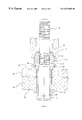
- FIGS. 4 through 9 illustrate successive stages in the installation of the fastener in a workpiece, the workpiece, sleeve, abutment member and installation tool anvil being shown in section, and the pin being shown in elevation;
- FIGS. 10 and 11 correspond to FIGS. 4 and 9 respectively, and illustrate a minor modification.
- the pin, sleeve and abutment member all have circular symmetry.
- the pin 11 (FIG. 1) is of medium carbon steel and comprises an elongated cylindrical shank 12 with an integral radially enlarged head 13 at one end of the shank, by means of which the pin engages with one end of the sleeve. Adjacent the head 13 the pin shank has a plain portion 14 , followed by a locking groove portion 15 and then a breakneck 16 which is the weakest part of the pin. Next to this there is another plain portion 17 , followed by a pulling groove portion 18 (part shown broken away for conveniece of illustration), which grooves are for engagement by the jaws of the fastener installation tool.
- Such a form of pin is well known in the design and practice of fasteners of the pin and collar type, for example those commercially available under the Registered Trade Mark AVDELOK.
- the sleeve 21 (FIG. 2) is generally cylindrical and is made of low carbon steel. It has a through bore 22 of uniform diameter which is a sliding fit on the pin shank 12 , and a cylindrical shank 23 which is of uniform external diameter. At one end (the tail end) the sleeve shank has a flat end face 24 and at the other end (the head end) an integrally formed radially enlarged head 25 .
- the sleeve head comprises a flange 26 having a flat annular underhead face 27 .
- a frangible element 28 Formed integrally with the head flange 26 is a frangible element 28 in the form of a radially projecting flange which projects radially beyond the underhead face 27 and is also spaced axially from the underhead face 27 .
- the head flange and frangible flange have a common flat top face 29 , but the frangible flange 28 is thinner than the head flange 26 , thereby producing the aforementioned axial spacing between their lower faces, occupied by the outer circumferential face 31 of the lower part of the head flange 26 .
- the sleeve shank includes a radially expandable portion which is centred on a softened zone 19 which, as indicated in FIG. 2, in this example extends axially from a position about halfway along the length of the sleeve shank 21 to a position about three quarters of the way from the sleeve head 26 towards the sleeve tail 24 .
- this softened portion 19 is made softer than the remainder of the sleeve by band annealing.
- the abutment member (FIG. 3) is in the form of a collar 32 made of low carbon steel. It has a through bore 33 which is an interference fit on the pin shank 12 .
- the peripheral edge of the upper part of the collar has a bevel, whilst the lower end has a radially projecting flange 35 .
- the bottom face 36 is flat, but is annular, since it is provided with a double recess 37 .
- the recess 37 is generally circular on the axis of the collar, and comprises an outer recess 38 and an inner recess 39 of smaller diameter than the outer recess 38 .
- the outer recess is of a diameter and depth suitable to receive the frangible flange 28 of the sleeve, having an annular bottom face 41 which surrounds the inner recess 39 .
- This inner recess has a diameter suitable to receive the circumferential face 31 of the sleeve head, and the total axial depth of the two recesses is rather greater than the total axial thickness of the sleeve head 25 .
- the pin, sleeve and collar are assembled together to form a fastener in the way illustrated in FIG. 4 .
- the sleeve is assembled on the pin shank 12 so that the sleeve end face 24 abuts the annular face of the pin head 13
- the collar 32 is then assembled on the pin shank so that the annular recess face 41 abuts the sleeve head top face 29 on the radially protruding annular upper face of the frangible flange 28 .
- the pin plain portion 17 protrudes from the top face of the collar 32 .
- the collar is temporarily secured to the pin in this position by its interference fit on the pin shank, to prevent disassembly of the fastener during handling.
- the fastener is used to secure together two structural metal panels 42 , 43 which have a cylindrical aperture 44 through them in which the sleeve 21 is a clearance fit.
- the panels 42 , 43 initially are spaced apart by a gap 20 , which the fastener will close up before it secures the panels together.
- the total thickness of the workpiece formed by the panels 42 and 43 and the gap 20 is rather more than half of the length of the sleeve shank 23 , so that the nearer end of the sleeve softened zone 19 indicated in FIG. 1 lies inside the remote face 46 of the workpiece when the underhead face 27 of the sleeve head contacts the near face 45 of the workpiece.
- the fastener is now installed by applying a progressively increasing pull to the protruding part of the pin 11 in relation to the sleeve 21 .
- This is done by means of a standard hydraulically-powered fastener placing tool, such as that commercially available under the designation AVDEL (Registered Trade Mark) Type 722, which is used for installing pin and collar type fasteners previously referred to.
- AVDEL Registered Trade Mark
- the tool includes an annular anvil 47 (FIG. 5) having an internal throat 48 shaped appropriately to swage the collar 32 .
- the tool also includes jaws (not shown) which engage with the pulling grooves in the portion 18 of the pin, and a hydraulic piston and cylinder device (not shown) for applying a progressively increasing retraction force to the jaws with respect to the anvil.
- Such tools and their manner of use are well known to those who use blind fasteners, and need not be described in detail here.
- the tool is offered up to the protruding part of the pin, so that the outer end of the anvil throat contacts the top of the collar 32 around its bevel 34 , as illustrated in FIG. 5 .
- the tool is then actuated so that its jaws engage the pulling groove portion 18 of the pin and exert a progressively increasing pull on it with respect to the anvil 47 .
- This reaction force is transmitted through the collar 32 to its recess annular face 41 , and thence via the face of the frangible portion 28 of the collar to the sleeve.
- the collar is thus axially compressed between the face of the flange 28 and its end face 24 in contact with the pin head 13 .
- the softened portion of the sleeve deforms by bulbing outwardly, to progressively form a blind head in contact with rear face 46 of the workpiece.
- the blind head progressively forms, it exerts a compressive force on the rear face 46 of rear panel 43 , which urges the panels 42 , 43 together and so closes the gap 20 so that the panels are finally in contact with each other and compressed together between the sleeve head 25 and the blind head.
- the final form of the blind head in this example, is illustrated at 49 in FIG. 5 .
- the frangible flange 28 is strong enough to support the force needed to fully form the blind head 49 , but as the force on the collar 32 is further increased the frangible flange 28 shears off from the main body of the sleeve head 25 .
- the collar 32 is driven down the pin shank towards the workpiece. Since the flange 28 is no thicker than the collar's outer recess 38 , the underface 36 of the collar contacts the near face 45 of the workpiece, as illustrated in FIG. 6 . Since the collars inner recess 39 and outer recess 38 have a total depth greater than the thickness of the sleeve head 25 , there is a gap 51 above the sleeve head.
- the anvil 47 is pushed down over the exterior of the collar, so that the anvil throat 48 swages the collar 32 radially inwardly into the locking grooves 15 on the pin.
- the anvil stops with its lower face near the flange at the bottom of the collar. This position is illustrated in FIG. 7 .
- the fastener described in the foregoing example is advantageous over that described in prior art EP 0705986 A in that it comprises less parts, and is therefore less expensive to manufacture and assemble. Furthermore, the prior art fastener initially forms its blind head spaced apart from the rear face of the workpiece, and then pulls the sleeve into the workpiece so that the blind head engages the rear face of the workpiece. This requires the provision of a sufficiently long space within the abutment member to accommodate the end of the retracted sleeve. The length of retraction will increase with decreasing grip length.
- the blind head is formed in contact with the rear face of the workpiece, decreasing grip length and closure of any initial gap between the workpiece members being accommodated by increasing radial extent of the blind head, so that the overall length of the fastener can be reduced compared with the prior art.
- the invention is not restricted to the details of the foregoing example.
- the pin 11 instead of the pin 11 being pulled into the sleeve 21 by a retracting jaw type of tool, it could be pulled in by a rotating nut arrangement similar to that described in EP 0705986 A.
- the abutment member 32 need not be permanently secured to the pin 11 but could be removably secured thereto, for example by means of a separate rotating nut arrangement, as also described in EP 0705986 A.
- the separate nut could be avoided by making the abutment member itself in threaded engagement with the pin.
- the load at which the frangible element breaks can be controlled by selecting the area over which is initially integral with the sleeve head, for example by selecting the thickness of the frangible element 28 , or by providing an annular groove, of the same diameter of the sleeve head 25 , in the top face or the under face of the frangible element 28 .
- frangible element 28 need not be integral with the sleeve head 25 , but could be provided as a separate annular element, as also described in EP 0705986 A, although this would not be so advantageous in reducing the number of components.
Landscapes
- Engineering & Computer Science (AREA)
- General Engineering & Computer Science (AREA)
- Mechanical Engineering (AREA)
- Insertion Pins And Rivets (AREA)
- Slide Fasteners (AREA)
- Slide Fasteners, Snap Fasteners, And Hook Fasteners (AREA)
- Surgical Instruments (AREA)
- Apparatus For Radiation Diagnosis (AREA)
- Portable Nailing Machines And Staplers (AREA)
- Dowels (AREA)
- Orthopedics, Nursing, And Contraception (AREA)
Applications Claiming Priority (3)
| Application Number | Priority Date | Filing Date | Title |
|---|---|---|---|
| GB9827647A GB2344864A (en) | 1998-12-17 | 1998-12-17 | Blind fastener |
| GB9827647 | 1998-12-17 | ||
| PCT/GB1999/003862 WO2000036309A1 (en) | 1998-12-17 | 1999-11-22 | Blind fastener |
Publications (1)
| Publication Number | Publication Date |
|---|---|
| US6537005B1 true US6537005B1 (en) | 2003-03-25 |
Family
ID=10844293
Family Applications (1)
| Application Number | Title | Priority Date | Filing Date |
|---|---|---|---|
| US09/831,857 Expired - Lifetime US6537005B1 (en) | 1998-12-17 | 1999-11-22 | Blind fastener |
Country Status (16)
| Country | Link |
|---|---|
| US (1) | US6537005B1 (de) |
| EP (1) | EP1141560B1 (de) |
| JP (1) | JP4114908B2 (de) |
| KR (1) | KR100732306B1 (de) |
| CN (1) | CN1283930C (de) |
| AT (1) | ATE280334T1 (de) |
| AU (1) | AU752826B2 (de) |
| BR (1) | BR9916287A (de) |
| CA (1) | CA2351467C (de) |
| DE (1) | DE69921359T2 (de) |
| DK (1) | DK1141560T3 (de) |
| ES (1) | ES2230918T3 (de) |
| GB (1) | GB2344864A (de) |
| MX (1) | MXPA01005668A (de) |
| WO (1) | WO2000036309A1 (de) |
| ZA (1) | ZA200103614B (de) |
Cited By (43)
| Publication number | Priority date | Publication date | Assignee | Title |
|---|---|---|---|---|
| US20030149487A1 (en) * | 2002-02-04 | 2003-08-07 | Doubler Robert L. | Skeletal fixation device with linear connection |
| US20030159387A1 (en) * | 2002-02-25 | 2003-08-28 | Soheil Eshraghi | Honeycomb rivet |
| US20030215303A1 (en) * | 2002-04-26 | 2003-11-20 | Takanori Makino | Blind rivet and fastening method |
| US20050008448A1 (en) * | 2003-07-09 | 2005-01-13 | Doubler Robert L. | Precise linear fastener system and method for use |
| US20050013678A1 (en) * | 2003-07-16 | 2005-01-20 | Smith Daniel R. | Three part blind fastener |
| US20050070899A1 (en) * | 2003-09-26 | 2005-03-31 | Doubler Robert L. | Polyaxial bone screw with torqueless fastening |
| US20050129459A1 (en) * | 2003-12-10 | 2005-06-16 | Doubler Robert L. | Internally disposed linear fastener system |
| US20050137594A1 (en) * | 2002-02-04 | 2005-06-23 | Doubler Robert L. | Spinal fixation assembly |
| US20050260056A1 (en) * | 2000-10-19 | 2005-11-24 | Keith Denham | Blind fastener |
| US20060251490A1 (en) * | 2003-05-14 | 2006-11-09 | Kleinman Jeffrey R | Blind fastener and method of removing it from a workpiece |
| US20070059120A1 (en) * | 2005-09-15 | 2007-03-15 | Vigliotti Daniel P | Blind rivet and method |
| US20070110541A1 (en) * | 2005-10-28 | 2007-05-17 | Fatigue Technology, Inc. | Radially displaceable bushing for retaining a member relative to a structural workpiece |
| US20070248432A1 (en) * | 2006-04-21 | 2007-10-25 | Cassatt Gary G | Low cost/high performance blind fastener |
| US20070289351A1 (en) * | 2006-04-27 | 2007-12-20 | Fatigue Technology, Inc. | Wave relieving geometric features in structural members that are radially expandable into workpieces |
| US7334307B1 (en) | 2006-05-23 | 2008-02-26 | Tomasz K Helenowski | Disposable set screw system |
| US20080213063A1 (en) * | 2006-10-05 | 2008-09-04 | Pratt John D | Dual-action disposable clamp |
| US20080219797A1 (en) * | 2005-05-31 | 2008-09-11 | Sumanjit Singh | Rivet |
| US20080315715A1 (en) * | 2007-06-21 | 2008-12-25 | Emerson Electric Co. | Rotor core assembly for electric motor |
| US20090092462A1 (en) * | 2006-10-05 | 2009-04-09 | Pratt John D | Dual-action disposable clamp |
| US20090178262A1 (en) * | 2007-10-16 | 2009-07-16 | Fatigue Technology, Inc. | Expandable fastener assembly with deformed collar |
| WO2009108787A1 (en) * | 2008-02-27 | 2009-09-03 | Newfrey Llc | Method for fastening a component and fastener for carrying out the method |
| US20090304315A1 (en) * | 2006-01-11 | 2009-12-10 | Fatigue Technology, Inc. | Bushing kits, bearings, and methods of installation |
| US20100000280A1 (en) * | 2008-03-07 | 2010-01-07 | Leonard Frederick Reid | Expandable member with wave inhibitor and methods of using the same |
| US20100074710A1 (en) * | 2007-02-07 | 2010-03-25 | Pierre Auriol | High-performance blind rivet particularly for structural attachment |
| US20100327505A1 (en) * | 2006-10-05 | 2010-12-30 | Pratt John D | Low profile dual-action disposable clamp |
| US20110150599A1 (en) * | 2009-12-16 | 2011-06-23 | Fatigue Technology, Inc. | Modular nut plate assemblies and methods of using the same |
| US7981143B2 (en) | 2003-09-10 | 2011-07-19 | Spinal Llc | Linear fastener system and method for use |
| US20120180279A1 (en) * | 2011-01-13 | 2012-07-19 | Airbus Operations (Sas) | Blind fastener equipped with a self-breaking holding system |
| CN102767552A (zh) * | 2012-08-06 | 2012-11-07 | 贵州航瑞科技有限公司 | 新型钛合金抽芯铆钉 |
| US8353193B2 (en) | 2005-12-28 | 2013-01-15 | Fatigue Technology, Inc. | Mandrel assembly and method of using the same |
| US8387436B2 (en) | 2006-04-27 | 2013-03-05 | Fatigue Technology, Inc. | Alignment device and methods of using the same |
| US8402806B2 (en) | 2006-08-28 | 2013-03-26 | Fatigue Technology, Inc. | Installation/processing systems and methods of using the same |
| US8506222B2 (en) | 2008-07-18 | 2013-08-13 | Fatigue Technology, Inc. | Nut plate assembly and methods of using the same |
| US8636455B2 (en) | 2009-04-10 | 2014-01-28 | Fatigue Technoloy, Inc. | Installable assembly having an expandable outer member and a fastener with a mandrel |
| US8763229B2 (en) | 2011-06-03 | 2014-07-01 | Fatigue Technology, Inc. | Expandable crack inhibitor method |
| US8938886B2 (en) | 2012-01-30 | 2015-01-27 | Fatigue Technology, Inc. | Smart installation/processing systems, components, and methods of operating the same |
| US20150082798A1 (en) * | 2013-09-25 | 2015-03-26 | Rolls-Royce Plc | Component for attaching to a wall |
| US9114449B2 (en) | 2011-06-15 | 2015-08-25 | Fatigue Technology, Inc. | Modular nut plates with closed nut assemblies |
| US20180328037A1 (en) * | 2016-10-31 | 2018-11-15 | Yue Zhang | Hollow pipe-sandwiching metal plate and applications thereof |
| US10457414B2 (en) * | 2016-12-13 | 2019-10-29 | Arconic Inc. | Reduced electromagnetic signature of conforming conical seal fastener systems |
| USD924045S1 (en) * | 2019-10-22 | 2021-07-06 | Domido Limited | Connecting metal nut |
| CN118875469A (zh) * | 2024-09-27 | 2024-11-01 | 一汽华翔轻量化科技(长春)有限公司 | 一种高精度热成形件激光切割夹具 |
| US12292065B2 (en) | 2022-02-11 | 2025-05-06 | The Boeing Company | Structural blind sleeves and associated systems and methods for clamping a first structure relative to a second structure to yield a clamped-up structure |
Families Citing this family (15)
| Publication number | Priority date | Publication date | Assignee | Title |
|---|---|---|---|---|
| GB2344864A (en) * | 1998-12-17 | 2000-06-21 | Textron Fastening Syst Ltd | Blind fastener |
| GB2368889B (en) * | 2000-11-09 | 2004-02-04 | Textron Fastening Syst Ltd | Method of manufacturing a blind threaded insert |
| GB0311053D0 (en) * | 2003-05-14 | 2003-06-18 | Textron Fastening Syst Ltd | Blind fastener |
| GB2401661B (en) * | 2003-05-16 | 2006-03-29 | Textron Fastening Syst Ltd | Blind fastener and method of installation thereof |
| US6868757B2 (en) * | 2003-05-20 | 2005-03-22 | Huck International, Inc. | Blind fastener and nose assembly for installation of the blind fastener |
| CA2556037A1 (en) * | 2004-02-04 | 2005-08-18 | Telezygology Inc. | Fasteners, especially temporary fasteners |
| DE102008023666A1 (de) * | 2008-05-15 | 2009-11-19 | Horst Kunkel | Vorrichtung zur Befestigung von Lasten an Hohlraumdecken und dergleichen |
| GB2463043B (en) * | 2008-08-29 | 2013-01-30 | Avdel Uk Ltd | Blind fastener |
| FR2939057B1 (fr) * | 2008-11-28 | 2010-11-12 | Renault Sas | Dispositif de sertissage d'un element a sertir sur une piece |
| US8985923B2 (en) * | 2013-03-13 | 2015-03-24 | Alcoa Inc. | Blind Fastener |
| CN105765241B (zh) * | 2013-09-09 | 2018-10-12 | 阿福德英国有限公司 | 锁紧螺栓 |
| CN108661999B (zh) * | 2018-07-24 | 2023-07-07 | 浙江哈特惠科技股份有限公司 | 一种单边螺栓紧固件 |
| DE102019208099A1 (de) * | 2019-06-04 | 2020-12-10 | Vitesco Technologies Germany Gmbh | Rotor für eine elektrische Maschine, Verfahren zur Herstellung eines Rotors und elektrische Maschine mit einem Rotor |
| CN111396428A (zh) * | 2020-04-14 | 2020-07-10 | 眉山中车紧固件科技有限公司 | 一种单槽单面紧固件及其安装方法 |
| CN113530943B (zh) * | 2021-06-28 | 2025-02-11 | 东南大学 | 一种高预紧力扭剪型高强度单边自紧螺栓及使用方法 |
Citations (6)
| Publication number | Priority date | Publication date | Assignee | Title |
|---|---|---|---|---|
| GB830447A (en) | 1956-02-03 | 1960-03-16 | Huck Mfg Co | Pull gun |
| US3937123A (en) | 1974-04-08 | 1976-02-10 | Textron Inc. | Blind fastener with shear washer |
| EP0286244A1 (de) | 1987-03-19 | 1988-10-12 | Avdel Systems Limited | Selbstdichtender Blindniet |
| US5213460A (en) * | 1991-05-24 | 1993-05-25 | Huck International, Inc. | High strength blind bolt with uniform high clamp over an extended grip range |
| EP0705986A1 (de) | 1994-10-03 | 1996-04-10 | Huck International, Inc. | Blindniet |
| US6247883B1 (en) * | 1999-07-13 | 2001-06-19 | Huck International, Inc. | High strength blind bolt with uniform high clamp over an extended grip range |
Family Cites Families (2)
| Publication number | Priority date | Publication date | Assignee | Title |
|---|---|---|---|---|
| US4681494A (en) * | 1985-10-04 | 1987-07-21 | Monogram Industries, Inc. | Drive nut blend fastener with cap nut |
| GB2344864A (en) * | 1998-12-17 | 2000-06-21 | Textron Fastening Syst Ltd | Blind fastener |
-
1998
- 1998-12-17 GB GB9827647A patent/GB2344864A/en not_active Withdrawn
-
1999
- 1999-11-22 CN CNB998145645A patent/CN1283930C/zh not_active Expired - Fee Related
- 1999-11-22 KR KR1020017007357A patent/KR100732306B1/ko not_active Expired - Fee Related
- 1999-11-22 US US09/831,857 patent/US6537005B1/en not_active Expired - Lifetime
- 1999-11-22 ES ES99973426T patent/ES2230918T3/es not_active Expired - Lifetime
- 1999-11-22 DK DK99973426T patent/DK1141560T3/da active
- 1999-11-22 DE DE69921359T patent/DE69921359T2/de not_active Expired - Lifetime
- 1999-11-22 AU AU13952/00A patent/AU752826B2/en not_active Ceased
- 1999-11-22 CA CA002351467A patent/CA2351467C/en not_active Expired - Fee Related
- 1999-11-22 MX MXPA01005668A patent/MXPA01005668A/es not_active IP Right Cessation
- 1999-11-22 EP EP99973426A patent/EP1141560B1/de not_active Expired - Lifetime
- 1999-11-22 AT AT99973426T patent/ATE280334T1/de not_active IP Right Cessation
- 1999-11-22 WO PCT/GB1999/003862 patent/WO2000036309A1/en not_active Ceased
- 1999-11-22 JP JP2000588520A patent/JP4114908B2/ja not_active Expired - Lifetime
- 1999-11-22 BR BR9916287-3A patent/BR9916287A/pt not_active IP Right Cessation
-
2001
- 2001-05-04 ZA ZA200103614A patent/ZA200103614B/en unknown
Patent Citations (6)
| Publication number | Priority date | Publication date | Assignee | Title |
|---|---|---|---|---|
| GB830447A (en) | 1956-02-03 | 1960-03-16 | Huck Mfg Co | Pull gun |
| US3937123A (en) | 1974-04-08 | 1976-02-10 | Textron Inc. | Blind fastener with shear washer |
| EP0286244A1 (de) | 1987-03-19 | 1988-10-12 | Avdel Systems Limited | Selbstdichtender Blindniet |
| US5213460A (en) * | 1991-05-24 | 1993-05-25 | Huck International, Inc. | High strength blind bolt with uniform high clamp over an extended grip range |
| EP0705986A1 (de) | 1994-10-03 | 1996-04-10 | Huck International, Inc. | Blindniet |
| US6247883B1 (en) * | 1999-07-13 | 2001-06-19 | Huck International, Inc. | High strength blind bolt with uniform high clamp over an extended grip range |
Non-Patent Citations (1)
| Title |
|---|
| A copy of the International Search Report which issued during the International Phase of the present application. |
Cited By (79)
| Publication number | Priority date | Publication date | Assignee | Title |
|---|---|---|---|---|
| US20050260056A1 (en) * | 2000-10-19 | 2005-11-24 | Keith Denham | Blind fastener |
| US20050137594A1 (en) * | 2002-02-04 | 2005-06-23 | Doubler Robert L. | Spinal fixation assembly |
| US7678136B2 (en) | 2002-02-04 | 2010-03-16 | Spinal, Llc | Spinal fixation assembly |
| US20030149487A1 (en) * | 2002-02-04 | 2003-08-07 | Doubler Robert L. | Skeletal fixation device with linear connection |
| US7105029B2 (en) | 2002-02-04 | 2006-09-12 | Zimmer Spine, Inc. | Skeletal fixation device with linear connection |
| US20030159387A1 (en) * | 2002-02-25 | 2003-08-28 | Soheil Eshraghi | Honeycomb rivet |
| US6898918B2 (en) * | 2002-02-25 | 2005-05-31 | Textron Inc. | Honeycomb rivet |
| US20030215303A1 (en) * | 2002-04-26 | 2003-11-20 | Takanori Makino | Blind rivet and fastening method |
| US7156596B2 (en) * | 2002-04-26 | 2007-01-02 | Newfrey Llc | Blind rivet and fastening method |
| US20060251490A1 (en) * | 2003-05-14 | 2006-11-09 | Kleinman Jeffrey R | Blind fastener and method of removing it from a workpiece |
| US7980800B2 (en) * | 2003-05-14 | 2011-07-19 | Avdel Uk Limited | Blind fastener and method of removing it from a workpiece |
| US7658582B2 (en) * | 2003-07-09 | 2010-02-09 | Ortho Innovations, Llc | Precise linear fastener system and method for use |
| WO2005008080A1 (en) * | 2003-07-09 | 2005-01-27 | Doubler Robert L | Precise linear fastener system and method for use |
| US20050008448A1 (en) * | 2003-07-09 | 2005-01-13 | Doubler Robert L. | Precise linear fastener system and method for use |
| US20050013678A1 (en) * | 2003-07-16 | 2005-01-20 | Smith Daniel R. | Three part blind fastener |
| EP1498617A3 (de) * | 2003-07-16 | 2006-04-19 | Newfrey LLC | Dreiteiliger Blindbefestiger |
| US7303366B2 (en) * | 2003-07-16 | 2007-12-04 | Newfrey Llc | Three part blind fastener |
| US7981143B2 (en) | 2003-09-10 | 2011-07-19 | Spinal Llc | Linear fastener system and method for use |
| US7335201B2 (en) | 2003-09-26 | 2008-02-26 | Zimmer Spine, Inc. | Polyaxial bone screw with torqueless fastening |
| US20050070899A1 (en) * | 2003-09-26 | 2005-03-31 | Doubler Robert L. | Polyaxial bone screw with torqueless fastening |
| US20070025813A1 (en) * | 2003-12-10 | 2007-02-01 | Zimmer Spine, Inc. | Internally Disposed Linear Fastener System |
| US20050129459A1 (en) * | 2003-12-10 | 2005-06-16 | Doubler Robert L. | Internally disposed linear fastener system |
| US7118303B2 (en) | 2003-12-10 | 2006-10-10 | Zimmer Spine, Inc. | Internally disposed linear fastener system |
| US7334961B2 (en) | 2003-12-10 | 2008-02-26 | Zimmer Spine, Inc. | Internally disposed linear fastener system |
| US7955035B2 (en) * | 2005-05-31 | 2011-06-07 | Sumanjit Singh | Rivet |
| US20080219797A1 (en) * | 2005-05-31 | 2008-09-11 | Sumanjit Singh | Rivet |
| US20070059120A1 (en) * | 2005-09-15 | 2007-03-15 | Vigliotti Daniel P | Blind rivet and method |
| US7887273B2 (en) | 2005-09-15 | 2011-02-15 | Newfrey Llc | Blind rivet and method |
| US20070110541A1 (en) * | 2005-10-28 | 2007-05-17 | Fatigue Technology, Inc. | Radially displaceable bushing for retaining a member relative to a structural workpiece |
| US8353193B2 (en) | 2005-12-28 | 2013-01-15 | Fatigue Technology, Inc. | Mandrel assembly and method of using the same |
| US8568034B2 (en) | 2006-01-11 | 2013-10-29 | Fatigue Technology, Inc. | Bushing kits, bearings, and methods of installation |
| US20090304315A1 (en) * | 2006-01-11 | 2009-12-10 | Fatigue Technology, Inc. | Bushing kits, bearings, and methods of installation |
| US20070248432A1 (en) * | 2006-04-21 | 2007-10-25 | Cassatt Gary G | Low cost/high performance blind fastener |
| US20100296895A1 (en) * | 2006-04-21 | 2010-11-25 | The Boeing Company | Lost cost/high performance blind fastener |
| US8387436B2 (en) | 2006-04-27 | 2013-03-05 | Fatigue Technology, Inc. | Alignment device and methods of using the same |
| US20070289351A1 (en) * | 2006-04-27 | 2007-12-20 | Fatigue Technology, Inc. | Wave relieving geometric features in structural members that are radially expandable into workpieces |
| US7334307B1 (en) | 2006-05-23 | 2008-02-26 | Tomasz K Helenowski | Disposable set screw system |
| US8402806B2 (en) | 2006-08-28 | 2013-03-26 | Fatigue Technology, Inc. | Installation/processing systems and methods of using the same |
| US20100327505A1 (en) * | 2006-10-05 | 2010-12-30 | Pratt John D | Low profile dual-action disposable clamp |
| US20080213063A1 (en) * | 2006-10-05 | 2008-09-04 | Pratt John D | Dual-action disposable clamp |
| US8517649B2 (en) * | 2006-10-05 | 2013-08-27 | Monogram Aerospace Fasteners, Inc. | Dual-action disposable clamp |
| US8511952B2 (en) | 2006-10-05 | 2013-08-20 | Monogram Aerospace Fasteners, Inc. | Dual-action disposable clamp |
| US20090226278A1 (en) * | 2006-10-05 | 2009-09-10 | Pratt John D | Deformable sleeve for a dual-action clamp |
| US8398345B2 (en) * | 2006-10-05 | 2013-03-19 | Monogram Aerospace Fasteners, Inc. | Low profile dual-action disposable clamp |
| US20090092462A1 (en) * | 2006-10-05 | 2009-04-09 | Pratt John D | Dual-action disposable clamp |
| US20090191020A1 (en) * | 2006-10-05 | 2009-07-30 | Pratt John D | Dual action disposable clamp |
| US8608417B2 (en) | 2006-10-05 | 2013-12-17 | Monogram Aerospace Fasteners, Inc. | Dual action disposable clamp |
| US8297897B2 (en) * | 2007-02-07 | 2012-10-30 | Eris Sarl | High-performance blind rivet particularly for structural attachment |
| US20100074710A1 (en) * | 2007-02-07 | 2010-03-25 | Pierre Auriol | High-performance blind rivet particularly for structural attachment |
| US20080315715A1 (en) * | 2007-06-21 | 2008-12-25 | Emerson Electric Co. | Rotor core assembly for electric motor |
| US7919898B2 (en) | 2007-06-21 | 2011-04-05 | Nidec Motor Corporation | Rotor core assembly for electric motor |
| US8312606B2 (en) * | 2007-10-16 | 2012-11-20 | Fatigue Technology, Inc. | Expandable fastener assembly with deformed collar |
| US20090178262A1 (en) * | 2007-10-16 | 2009-07-16 | Fatigue Technology, Inc. | Expandable fastener assembly with deformed collar |
| WO2009108787A1 (en) * | 2008-02-27 | 2009-09-03 | Newfrey Llc | Method for fastening a component and fastener for carrying out the method |
| US10010983B2 (en) | 2008-03-07 | 2018-07-03 | Fatigue Technology, Inc. | Expandable member with wave inhibitor and methods of using the same |
| US20100000280A1 (en) * | 2008-03-07 | 2010-01-07 | Leonard Frederick Reid | Expandable member with wave inhibitor and methods of using the same |
| US8506222B2 (en) | 2008-07-18 | 2013-08-13 | Fatigue Technology, Inc. | Nut plate assembly and methods of using the same |
| US8636455B2 (en) | 2009-04-10 | 2014-01-28 | Fatigue Technoloy, Inc. | Installable assembly having an expandable outer member and a fastener with a mandrel |
| US8647035B2 (en) | 2009-12-16 | 2014-02-11 | Fatigue Technology, Inc. | Modular nut plate assemblies and methods of using the same |
| US20110150599A1 (en) * | 2009-12-16 | 2011-06-23 | Fatigue Technology, Inc. | Modular nut plate assemblies and methods of using the same |
| US20120180279A1 (en) * | 2011-01-13 | 2012-07-19 | Airbus Operations (Sas) | Blind fastener equipped with a self-breaking holding system |
| US9163652B2 (en) * | 2011-01-13 | 2015-10-20 | Airbus Operations (Sas) | Blind fastener equipped with a self-breaking holding system |
| US8763229B2 (en) | 2011-06-03 | 2014-07-01 | Fatigue Technology, Inc. | Expandable crack inhibitor method |
| US9114449B2 (en) | 2011-06-15 | 2015-08-25 | Fatigue Technology, Inc. | Modular nut plates with closed nut assemblies |
| US8938886B2 (en) | 2012-01-30 | 2015-01-27 | Fatigue Technology, Inc. | Smart installation/processing systems, components, and methods of operating the same |
| US10843250B2 (en) | 2012-01-30 | 2020-11-24 | Fatigue Technology, Inc. | Smart installation/processing systems, components, and methods of operating the same |
| US10130985B2 (en) | 2012-01-30 | 2018-11-20 | Fatigue Technology, Inc. | Smart installation/processing systems, components, and methods of operating the same |
| CN102767552A (zh) * | 2012-08-06 | 2012-11-07 | 贵州航瑞科技有限公司 | 新型钛合金抽芯铆钉 |
| CN102767552B (zh) * | 2012-08-06 | 2014-12-10 | 贵州航瑞科技有限公司 | 新型钛合金抽芯铆钉 |
| US9903589B2 (en) * | 2013-09-25 | 2018-02-27 | Rolls-Royce Plc | Component for attaching to a wall |
| US20150082798A1 (en) * | 2013-09-25 | 2015-03-26 | Rolls-Royce Plc | Component for attaching to a wall |
| US10920422B2 (en) * | 2016-10-31 | 2021-02-16 | Yue Zhang | Hollow pipe-sandwiching metal plate and applications thereof |
| US20200217072A1 (en) * | 2016-10-31 | 2020-07-09 | Yue Zhang | Hollow pipe-sandwiching metal plate and applications thereof |
| US20180328037A1 (en) * | 2016-10-31 | 2018-11-15 | Yue Zhang | Hollow pipe-sandwiching metal plate and applications thereof |
| US11499313B2 (en) * | 2016-10-31 | 2022-11-15 | Yue Zhang | Hollow pipe-sandwiching metal plate and applications thereof |
| US10457414B2 (en) * | 2016-12-13 | 2019-10-29 | Arconic Inc. | Reduced electromagnetic signature of conforming conical seal fastener systems |
| USD924045S1 (en) * | 2019-10-22 | 2021-07-06 | Domido Limited | Connecting metal nut |
| US12292065B2 (en) | 2022-02-11 | 2025-05-06 | The Boeing Company | Structural blind sleeves and associated systems and methods for clamping a first structure relative to a second structure to yield a clamped-up structure |
| CN118875469A (zh) * | 2024-09-27 | 2024-11-01 | 一汽华翔轻量化科技(长春)有限公司 | 一种高精度热成形件激光切割夹具 |
Also Published As
| Publication number | Publication date |
|---|---|
| KR20010101191A (ko) | 2001-11-14 |
| ZA200103614B (en) | 2001-11-26 |
| ES2230918T3 (es) | 2005-05-01 |
| DE69921359D1 (de) | 2004-11-25 |
| DE69921359T2 (de) | 2005-11-03 |
| JP4114908B2 (ja) | 2008-07-09 |
| ATE280334T1 (de) | 2004-11-15 |
| GB9827647D0 (en) | 1999-02-10 |
| EP1141560A1 (de) | 2001-10-10 |
| CN1330746A (zh) | 2002-01-09 |
| KR100732306B1 (ko) | 2007-06-25 |
| WO2000036309A1 (en) | 2000-06-22 |
| CA2351467A1 (en) | 2000-06-22 |
| MXPA01005668A (es) | 2003-07-14 |
| AU1395200A (en) | 2000-07-03 |
| EP1141560B1 (de) | 2004-10-20 |
| DK1141560T3 (da) | 2005-02-14 |
| BR9916287A (pt) | 2001-10-02 |
| JP2002532661A (ja) | 2002-10-02 |
| GB2344864A (en) | 2000-06-21 |
| CA2351467C (en) | 2007-04-10 |
| CN1283930C (zh) | 2006-11-08 |
| AU752826B2 (en) | 2002-10-03 |
Similar Documents
| Publication | Publication Date | Title |
|---|---|---|
| US6537005B1 (en) | Blind fastener | |
| EP0398512B1 (de) | Blindniet | |
| EP0958456B1 (de) | Blindniet und verfahren zu seiner herstellung | |
| EP0456431B1 (de) | Selbstdichtender Blindniet | |
| KR101022132B1 (ko) | 블라인드 패스너 및 워크피스로부터 그것을 제거하는 방법 | |
| EP1173680B1 (de) | Einen hochfesten blindkopf und einen hohen klemmspann- und scherkraftwiderstand aufweisendes blindbefestigungselement | |
| US5810530A (en) | Interference blind type bolt | |
| US6389676B1 (en) | Blind riveting | |
| EP1327082B1 (de) | Blindbefestiger | |
| US5697141A (en) | Method of securing members together | |
| GB2233059A (en) | Self plugging blind rivets | |
| ZA200507051B (en) | Blind fastener and method of removing it from a workpiece |
Legal Events
| Date | Code | Title | Description |
|---|---|---|---|
| AS | Assignment |
Owner name: TEXTRON FASTENING SYSTEMS LIMITED, UNITED KINGDOM Free format text: DOCUMENT PREVIOUSLY RECORDED AT REEL/FRAME 012217/0432 CONTAINED AN ERROR, SER. NO. 09981857, WHEN IT SHOULD BE 09831857. DOCUMENT RERECORDED TO CORRECT ERROR ON NOTICE OF RECORDATION ATTACHED;ASSIGNOR:DENHAM, KEITH;REEL/FRAME:012498/0558 Effective date: 20010904 |
|
| STCF | Information on status: patent grant |
Free format text: PATENTED CASE |
|
| FPAY | Fee payment |
Year of fee payment: 4 |
|
| AS | Assignment |
Owner name: AVDEL UK LIMITED, UNITED KINGDOM Free format text: CHANGE OF NAME;ASSIGNOR:TEXTRON FASTENING SYSTEMS LIMITED;REEL/FRAME:019297/0435 Effective date: 20061222 |
|
| FPAY | Fee payment |
Year of fee payment: 8 |
|
| FEPP | Fee payment procedure |
Free format text: PAYOR NUMBER ASSIGNED (ORIGINAL EVENT CODE: ASPN); ENTITY STATUS OF PATENT OWNER: LARGE ENTITY |
|
| FPAY | Fee payment |
Year of fee payment: 12 |