US6516652B1 - Design of viscoelastic coatings to reduce turbulent friction drag - Google Patents
Design of viscoelastic coatings to reduce turbulent friction drag Download PDFInfo
- Publication number
- US6516652B1 US6516652B1 US09/546,380 US54638000A US6516652B1 US 6516652 B1 US6516652 B1 US 6516652B1 US 54638000 A US54638000 A US 54638000A US 6516652 B1 US6516652 B1 US 6516652B1
- Authority
- US
- United States
- Prior art keywords
- velocity
- coating
- viscoelastic
- energy
- turbulent
- Prior art date
- Legal status (The legal status is an assumption and is not a legal conclusion. Google has not performed a legal analysis and makes no representation as to the accuracy of the status listed.)
- Ceased
Links
Images
Classifications
-
- F—MECHANICAL ENGINEERING; LIGHTING; HEATING; WEAPONS; BLASTING
- F15—FLUID-PRESSURE ACTUATORS; HYDRAULICS OR PNEUMATICS IN GENERAL
- F15D—FLUID DYNAMICS, i.e. METHODS OR MEANS FOR INFLUENCING THE FLOW OF GASES OR LIQUIDS
- F15D1/00—Influencing flow of fluids
- F15D1/10—Influencing flow of fluids around bodies of solid material
- F15D1/12—Influencing flow of fluids around bodies of solid material by influencing the boundary layer
-
- B—PERFORMING OPERATIONS; TRANSPORTING
- B63—SHIPS OR OTHER WATERBORNE VESSELS; RELATED EQUIPMENT
- B63B—SHIPS OR OTHER WATERBORNE VESSELS; EQUIPMENT FOR SHIPPING
- B63B1/00—Hydrodynamic or hydrostatic features of hulls or of hydrofoils
- B63B1/32—Other means for varying the inherent hydrodynamic characteristics of hulls
- B63B1/34—Other means for varying the inherent hydrodynamic characteristics of hulls by reducing surface friction
-
- B—PERFORMING OPERATIONS; TRANSPORTING
- B64—AIRCRAFT; AVIATION; COSMONAUTICS
- B64C—AEROPLANES; HELICOPTERS
- B64C21/00—Influencing air flow over aircraft surfaces by affecting boundary layer flow
- B64C21/10—Influencing air flow over aircraft surfaces by affecting boundary layer flow using other surface properties, e.g. roughness
-
- B—PERFORMING OPERATIONS; TRANSPORTING
- B64—AIRCRAFT; AVIATION; COSMONAUTICS
- B64C—AEROPLANES; HELICOPTERS
- B64C23/00—Influencing air flow over aircraft surfaces, not otherwise provided for
-
- Y—GENERAL TAGGING OF NEW TECHNOLOGICAL DEVELOPMENTS; GENERAL TAGGING OF CROSS-SECTIONAL TECHNOLOGIES SPANNING OVER SEVERAL SECTIONS OF THE IPC; TECHNICAL SUBJECTS COVERED BY FORMER USPC CROSS-REFERENCE ART COLLECTIONS [XRACs] AND DIGESTS
- Y02—TECHNOLOGIES OR APPLICATIONS FOR MITIGATION OR ADAPTATION AGAINST CLIMATE CHANGE
- Y02T—CLIMATE CHANGE MITIGATION TECHNOLOGIES RELATED TO TRANSPORTATION
- Y02T50/00—Aeronautics or air transport
- Y02T50/10—Drag reduction
-
- Y—GENERAL TAGGING OF NEW TECHNOLOGICAL DEVELOPMENTS; GENERAL TAGGING OF CROSS-SECTIONAL TECHNOLOGIES SPANNING OVER SEVERAL SECTIONS OF THE IPC; TECHNICAL SUBJECTS COVERED BY FORMER USPC CROSS-REFERENCE ART COLLECTIONS [XRACs] AND DIGESTS
- Y02—TECHNOLOGIES OR APPLICATIONS FOR MITIGATION OR ADAPTATION AGAINST CLIMATE CHANGE
- Y02T—CLIMATE CHANGE MITIGATION TECHNOLOGIES RELATED TO TRANSPORTATION
- Y02T70/00—Maritime or waterways transport
- Y02T70/10—Measures concerning design or construction of watercraft hulls
Definitions
- the basic design approach was outlined in “On Conditions of Modelling and Choice of Viscoelastic Coatings for Drag Reduction,” in Recent Developments in Turbulence Management, K. S. Choi, ed., 1991, pp. 241-262, Dordrecht, Kluwer Publishers.
- the Novosibirsk design approach is semi-empirical in nature, and does not take into account the full characterization of the complex shear modulus of the viscoelastic material, namely, the relaxation time of the material.
- the Novosibirsk design approach does take into account frequency-dependent material properties.
- the Novosibirsk concept is valid only for a membrane-type coating, such as a film which coats a foam-rubber saturated with water or glycerine, and where only normal fluctuations of the surface are considered.
- Structural features include multiple layers of materials, longitudinal, rib-like inclusions of elastic, viscoelastic, or fluid materials, and heated elements. Viscoelastic coatings may be combined with other forms of structure, such as longitudinal riblets molded on or within the surface of the coating. As described in the international literature in publications such as “Secondary Flow Induced by Riblets,” written by D. B. Goldstein and T. C. Tuan, and published in the Journal of Fluid Mechanics, volume 363, May 25, 1998, pp. 115-152, two-dimensional, rigid riblets alone have been shown experimentally to reduce surface friction drag up to about 10%.
- the present invention enables the design of a passive viscoelastic coating for the reduction of turbulent friction drag. Coatings with material properties designed using the methodology described in this invention have reduced friction drag by greater than 10%.
- the methodology of the present invention permits, as a first object of the invention, the specification of the frequency dependent complex shear modulus, the density, and the thickness of an isotropic viscoelastic material which will reduce turbulent friction drag relative to specific flow conditions over a rigid surface. Quantitative levels of drag reduction can be estimated. Mathematical detail is provided for the cases of turbulent flow over a rigid flat plate as well as a viscoelastic flat plate, where the invention accounts for both normal and longitudinal oscillations of the surface.
- a second object of the invention is the specification of material properties for a coating composed of multiple layers of isotropic viscoelastic materials.
- a third object of the invention is the specification of material properties for a coating composed of an anisotropic material.
- a fourth object of the invention is the minimization of edge effects for coatings of finite length.
- a fifth object of the invention is the stabilization of longitudinal vortices through combination of viscoelastic coating design with additional structure, such as riblets.
- TBL turbulent boundary layer
- VE viscoelastic
- TBL problem a fluids task, involving the calculation of turbulent boundary layer parameters, given boundary conditions for a rigid, elastic, or viscoelastic surface
- materials task involving the calculation of the response of a viscoelastic or elastic surface to a periodic forcing function which approximates the loading of the turbulent boundary layer.
- the invention focuses upon cation of amplitudes of surface oscillations and velocities, and of the energy flux for a viscoelastic coating (hereinafter referred to as the VE problem).
- the TBL problem is first solved for a rigid surface, thus providing necessary input to describe the forcing function on the surface, and also providing baseline calculations of friction drag, for comparison.
- the VE problem is solved next, given a periodic forcing function that approximates the shear and pressure pulsations of a given boundary layer.
- Initial choices for material parameters are based on theoretical and empirical guidelines. Optimal material parameters are chosen, following a series of iterations, such that the following two criteria are met:
- the amplitudes of surface oscillation are less than the thickness of the viscous sublayer of the turbulent boundary layer over the coating.
- the turbulent friction drag over a viscoelastic, elastic, or rigid surface can be quantitatively evaluated.
- both dynamic and kinematic boundary conditions are specified. These boundary conditions are derived directly from the solution of the VE equations for energy flux and surface oscillation amplitudes, and then transferred into a dissipation boundary condition and Reynolds stress boundary conditions for solution of the TBL equations.
- Vertical oscillations influence the effective roughness of the surface, and the root-mean square (rms) value of the vertical oscillation amplitude is classified as the dynamic roughness.
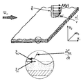
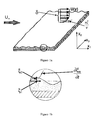
- FIG. 1 a is a schematic of the interaction of a passive viscoelastic surface with a turbulent boundary layer, where a low-amplitude traveling wave develops on the surface
- FIG. 1 b is an enlargement of the region within the circle shown in FIG. 1 a, and indicates displacement amplitudes
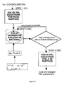
- FIG. 2 is a flowchart of the basic methodology required to a) choose a viscoelastic material that reduces turbulent friction drag under given flow conditions, and b) to quantify the value of drag reduction relative to a rigid surface, and
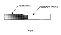
- FIG. 3 is a detail of a structure introduced at the intersection between a viscoelastic coating and a rigid surface in order to minimize local oscillation amplitude and edge effects.
- the present invention identifies physical and geometric parameters of a viscoelastic coating that reduces turbulent friction drag under given flow conditions. Furthermore, the invention permits evaluation of the anticipated drag reduction effectiveness of a given material with known physical properties for a given body configuration and set of flow conditions. The methodology has been applied principally to the characterization of coatings for turbulent flow over flat plates and bodies of revolution, and can also be applied to more complex geometries having curvature and nonzero pressure gradients.
- a fluid boundary layer is the very thin layer of fluid adjacent to a surface over which fluid is flowing. It is the region where frictional forces play a major role, and is where the flow adjusts from conditions at the surface to conditions in the freestream of the flow.
- a turbulent boundary layer is characterized by a spectrum of pressure and shear fluctuations, the frequency, phase speed, and amplitude characteristics of which are a function of such factors as freestream velocity, body configuration, surface conditions, and pressure gradient.
- the wall pressure and shear fluctuations act as a forcing function which can deform the surface, creating surface waves.
- energy from the turbulent boundary layer may be absorbed and dissipated by the coating, thus necessitating proper specification of boundary conditions for both Reynolds stresses and energy absorption at the wall (i.e., kinematic and dynamic boundary conditions).
- FIG. 1 is a schematic of a passive viscoelastic coating that interacts with a turbulent boundary layer of thickness, ⁇ .
- ⁇ a turbulent boundary layer of thickness
- ⁇ w is the shear stress at the wall and ⁇ is the density of the fluid.
- ⁇ is the density of the fluid.
- the interaction of the turbulent flow with a viscoelastic coating leads to the formation of a quasi-periodic surface wave.
- the motion and energy absorption of the coating in turn affect the energy balance in the turbulent boundary layer and the value of the friction drag, the latter of which is the surface integral of the wall shear stress.
- the methodology for this invention is schematically shown in FIG. 2 .
- the present invention includes solutions for: 1) turbulent boundary layer (TBL) parameters, including friction drag over rigid, viscoelastic, or elastic plates; and, 2) energy absorption and oscillation amplitudes of a viscoelastic (VE) plate excited by a periodic load which approximates that of a turbulent boundary layer.
- TBL turbulent boundary layer
- VE viscoelastic
- TBL parameters are first characterized for a rigid surface (step 1 ) and, once material properties are defined, for a viscoelastic material (step 3 ).
- step 1 material properties are defined
- step 3 material properties are defined
- the kinematic and dynamic boundary conditions are defined differently.
- a rigid surface there is no surface motion and no energy absorption.
- an elastic surface there is surface motion, but no energy absorption.
- a viscoelastic surface there is surface motion and energy absorption.
- Turbulent flow parameters are obtained through the solution of a system of equations of continuity, motion, and energy, with accompanying boundary conditions. These equations are developed from principles of conservation of mass, conservation of momentum (Newton's second law), and energy balance (as based on the first law of thermodynamics).
- Equation 3 the general equation of continuity for a compressible fluid having a density of ⁇ , and velocity components U, V, and W in the streamwise, normal, and transverse directions, is given by Equation 3, below.
- g i is the body force vector, due to external fields, such as gravity, which act on the element, and
- ⁇ is the kinematic viscosity (assumed to be constant).
- Turbulent velocity components may be described as the sum of the mean and fluctuating components, U i and u′, respectively, where U 1 , U 2 , and U 3 , are equivalent to U, V, and W and where u′ 1 , u′ 2 , and u′ 3 are equivalent to u′, v′, and w′:
- An overbar indicates time-averaging:
- Equations 7a-7c Substituting Equations 7a-7c into Equations 6a-6c and time-averaging yields the following system of three complex nonlinear second-order partial differential equations of motion for turbulent flow:
- U j ⁇ ⁇ U i ⁇ x j - 1 ⁇ ⁇ ⁇ ⁇ ⁇ x i + g i + v ⁇ ⁇ ⁇ 2 ⁇ U i ⁇ x j ⁇ ⁇ x j - ⁇ u i ′ ⁇ u j ′ _ ⁇ x j (Equations 9a-9b-9c)
- Equations 9a-9c the components ⁇ overscore (u′ 2 ) ⁇ , ⁇ overscore (v′ 2 ) ⁇ , and ⁇ overscore (w′ 2 ) ⁇ are termed normal Reynolds stresses, and the components in the form ⁇ overscore (u′v′) ⁇ , ⁇ overscore (v′w′) ⁇ , and ⁇ overscore (u′w′) ⁇ are termed Reynolds shear stresses.
- ⁇ ij is termed the pressure-strain correlation tensor
- J ijk is termed the diffusive flux of the Reynolds stresses
- ⁇ ij is termed the dissipation tensor.
- equations which are solved to determine turbulent boundary layer parameters include:
- Turbulent Boundary Layer Equations Complete mathematical formulations are provided for the specific case of a turbulent boundary layer with a steady, two-dimensional mean flow and a constant freestream velocity, U ⁇ .
- Two-dimensional turbulent boundary layer equations as termed in the literature, are derived from the general continuity equation (Equation 5) and equations of motion (Equations 9a-9c), given the assumptions that:
- the mean transverse velocity, W is zero.
- the pressure gradient is approximately zero in the y direction.
- the mean velocity in the streamwise direction, U is much greater than the mean velocity in the normal direction, V.
- the rate of change of parameters in the x direction is much smaller than the rate of change of parameters in the y direction.
- ⁇ ij C 1 ⁇ ( ⁇ k ) ⁇ ⁇ ( u i ′ ⁇ u j ′ _ - ⁇ ij ⁇ ⁇ 2 3 ⁇ k ) + C 2 ⁇ ( P ij - ⁇ ij ⁇ ⁇ 2 3 ⁇ P ⁇ ) + ⁇ ij , 1 ′ + ⁇ ij , 2 ′ + ⁇ ij , 3 ′ (Equations 20a–20d)
- ⁇ ′ ij,1 terms represent near-wall redistribution of turbulent energy from the streamwise component to the normal and transverse components
- the ⁇ ′ ij,2 terms represent near-wall variation of the Reynolds stress tensor component production
- the ⁇ ′ ij,3 terms represent near-wall redistribution of turbulent energy proportional to local vorticity:
- f ⁇ ( l y ) R t R k ⁇ ( 1 + 1 + 100 R t ) ( Equation ⁇ ⁇ 24 )
- ⁇ ij v ⁇ ⁇ ⁇ u i ′ ⁇ x k ⁇ ⁇ ⁇ u j ′ ⁇ x k _ ⁇ f s ⁇ u i ′ ⁇ u j ′ _ 2 ⁇ k ⁇ ⁇ + ( 1 - f s ) ⁇ 1 3 ⁇ ⁇ ij ⁇ ⁇ ⁇ (Equations 31a–31d)
- Equation (16) includes two functions, ⁇ 1 and ⁇ 2 , which also introduce corrections for near-wall flows:
- turbulent boundary layer parameters at different x and y locations are determined through solution of the continuity equation (Equation 13), the equation of motion in the x-direction (Equation 14), the transport equations for the Reynolds stresses ⁇ overscore (u′ 2 ) ⁇ , ⁇ overscore (v′ 2 ) ⁇ , ⁇ overscore (w′ 2 ) ⁇ , and ⁇ overscore (u′v′) ⁇ (Equations 15a-15d), and the equation for the isotropic energy dissipation rate (Equation 16), given appropriate boundary conditions.
- the problem is solved numerically using a finite difference approximation. All equations are reduced to a standard type of parabolic equation in terms of a given function, and solution is obtained at designated grid points in an (x,y) coordinate system.
- Boundary conditions are values of parameters at the limits of the boundary layer, i.e., at the surface and the freestream.
- the freestream velocity is defined as U ⁇ .
- Boundary conditions at the surface are specified for Reynolds normal and shear stresses (kinematic boundary conditions), as well as for the isotropic dissipation rate (dynamic boundary condition).
- ⁇ 1 and ⁇ 2 are the longitudinal and vertical surface displacement components, respectively, u* is the friction velocity (as previously defined), and ⁇ is the angle of the longitudinal axis relative to the mean flow in the x 1 -x 3 plane.
- mean velocities at the wall are assumed to be zero.
- phase speed corresponding to energy-carrying disturbances in the boundary layer is assumed to be:
- the first term reflects viscous dissipation and the second reflects absorption of energy by the viscoelastic material.
- the second term reflects absorption of energy by the viscoelastic material.
- Equations 13, 14, 15a-15d, and 16 are solved for mean velocity components, Reynolds normal and shear stresses, and energy dissipation, given the kinematic and dynamic boundary conditions (Equations (44) through (48)) based on the solution of the viscoelasticity problem (as described in the following section).
- Equations (44)-(46) may be approximated as zero.
- shear stresses in the near-wall region of the boundary layer decrease, as does the production of turbulence in the boundary layer.
- the surface can act as a dynamic roughness element and thereby enhance the level of turbulence generated within the boundary layer.
- the second part of the methodology determines the response of a viscoelastic material to a turbulent boundary layer (step 2 in FIG. 2 ).
- Reynolds stresses on the surface (Equations (44) to (47)) are zero, and the isotropic dissipation rate contains only the viscous term.
- ⁇ s is the material density
- ⁇ 2 and ⁇ 2 are the longitudinal and normal displacements through the thickness of the coating
- ⁇ ij is the amplitude of the stress tensor.
- the stress tensor for a viscoelastic material is written for a Kelvin-Voigt type of material as:
- ⁇ i Displacements, ⁇ i , are approximated as periodic, in the form of Equation (39), and can be expressed as a function of potentials of longitudinal and transverse (shear) waves:
- Equations (57) and (58) can be solved for the potentials, ⁇ and ⁇ , and hence for displacements, velocities, and stresses through the thickness of the coating, if boundary conditions are specified.
- the coating is fixed at its base, so that the longitudinal and normal displacements are zero, and the shear stress and pressure load on the surface is known.
- Pressure and shear pulsations on the coatings are approximated as periodic functions, with a form similar to that of the displacements in Equation (39), but with the following magnitudes, respectively:
- K p is the Kraichnan parameter, whose value is approximated as 2.5.
- shear pulsations are included, a phase shift between shear and pressure pulsations must also be introduced.
- ⁇ ( ⁇ ) is a dissipative function of the coating material.
- the flux of turbulent fluctuating energy through the surface can be solved for directly, as:
- Equation 68 provides a basis for determining the value of the kinematic coefficient of turbulence diffusion, ⁇ q , on an absorbing surface. Substituting Equation 68 into Equation 66 yields the following expression for ⁇ tilde over ( ⁇ ) ⁇ q , defined as ⁇ tilde over ( ⁇ ) ⁇ t
- K + max is the maximum of turbulence kinetic energy
- K + q is the kinetic energy of the oscillating surface, both quantities nondimensionalized by U ⁇ 2 .
- a methodology to choose properties of a viscoelastic coating that reduces turbulent friction drag necessarily requires both of the previously described solutions for turbulent boundary layer parameters and response of a viscoelastic material.
- the TBL problem is solved for a rigid plate, in order to determine the boundary layer thickness, ⁇ , at a given freestream velocity, U ⁇ , and location.
- the boundary layer thickness is determined from the finite difference solution of the seven equations of continuity, motion in the x-direction, transport equations for Reynolds normal and shear stresses, and the equation for dissipation rate, assuming no motion at the wall.
- the external limit of the boundary layer is defined as that location where the ratio of the mean velocity to the freestream velocity is a constant, ⁇ , between 0.95 and 1.0.
- the frequency-dependent, complex shear modulus of a material, ⁇ ( ⁇ ), can be expressed in different mathematical forms, some of which approximate experimentally measured shear modulus data more accurately than others.
- a single relaxation time (SRT) material is one where the complex shear modulus is expressed using a single relaxation time, ⁇ s , and a single value for the dynamic shear modulus, ⁇ 2 .
- SRT single relaxation time
- MRT multiple relaxation time
- Equation (77) For a HN type of material, whose complex shear modulus is expressed in the form of Equation (77), ⁇ ⁇ is the limiting high-frequency modulus and ⁇ HN and ⁇ HN are constants.
- K( ⁇ ) is essentially constant, with a value of approximately 1 ⁇ 10 8 Pa.
- An SRT material can be adequately characterized by the material thickness, H, the density, ⁇ s , the static shear modulus, ⁇ 0 , the dynamic shear modulus, ⁇ s , and the relaxation time, ⁇ .
- An appropriate density for the viscoelastic material, ⁇ s is within 10% that of water.
- the initial guess for the static shear modulus of the material, ⁇ 0 is:
- phase speed is assumed to be 0.8 of the value of the freestream velocity, U ⁇ (Equation 42). If the convective velocity exceeds the shear wave velocity, an instability occurs, and large waves appear on the surface of the material, leading to an increase of drag for the coating.
- the optimal desired thickness for a coating may be greater than practical for a given application. While isotropic coatings thinner than recommended in Equations 79-80 can still be effective, anisotropic coatings that are stiffer in the normal dimension relative to the transverse and longitudinal dimensions can provide equivalent performance with significant reduction in thickness.
- Equation 81 Given specified values of H, ⁇ 0 , and ⁇ s , the VE problem, as expressed in Equations (57) and (58), is solved numerically for a matrix of values of ⁇ s and ⁇ s (i.e., for different values of the complex shear modulus) and for a range of wavenumbers.
- Equation (41) the frequency, ⁇ e , for maximum energy-carrying disturbances is estimated by Equation (41).
- Calculations yield surface displacement amplitudes and the flux of turbulent fluctuating energy into the coating.
- the best combination of properties for a SRT material occurs where the surface displacement under actual load (Equation (61)) is less than the viscous sublayer thickness, and where the energy flux into the coating (Equation (57)) is at a maximum.
- Equation (61) the surface displacement under actual load
- Equation (57) the energy flux into the coating
- multi-layer isotropic coating properties of a complex shear modulus, density, and thickness are specified for individual layers, and non-slip boundary conditions between layers are imposed.
- the properties of the upper layer are specified according to the methodology for a single layer, and the lower layers will have progressively lower static shear moduli, as optimized for lower freestream velocities.
- well-designed multi-layer coatings can reduce drag over a range of freestream velocities.
- the complex shear modulus has different values in the normal direction relative to the longitudinal and transverse directions (hereinafter termed transversely isotropic). If the viscoelastic material follows a single-relaxation time model, then the static shear modulus, ⁇ 0 , the dynamic shear modulus, ⁇ s , and the relaxation time, ⁇ s , will differ with direction, as expressed in Equations (82) and (83). The static shear modulus in the normal direction, ⁇ 01 , will be greater than than in the longitudinal-transverse plane, ⁇ 02 .
- a further aspect of coating design is the choice of internal structure within the viscoelastic material.
- the coating will be finite in length, with leading, trailing, and side edges.
- the influence of the finite edges affects coating performance.
- Well posed edges can order and stabilize transverse and longitudinal vortical structures in the near-wall region of the flow and thereby delay the deformation of these vortical structures and enhance the stability of the flow.
- unstructured edges can accentuate the amplitude of oscillations of the viscoelastic material in this region. Local instabilities can degrade the performance of the coating, so that, even with a well-designed material, the influence of the edges can lead to a drag increase.
- the coating is structured in the vicinity of finite edges.
- the thickness of the coating is decreased to minimize such oscillations, using techniques such as a rigid wedge underneath the coating, or other localized structure near an edge (FIG. 3 ).
- a continuous coating may be impractical or difficult to fabricate.
- An alternative design is a piecewise continuous coating, composed of finite segments of coating, where both the longitudinal and transverse edges of the coating system are organized to stabilize flow structures and to minimize adverse effects at the edges of each segment.
- viscoelastic coatings may be combined with surface structure to enhance the stabilization of longitudinal vortices along the length of the coating, and hence to increase the level of drag reduction through multiple physical mechanisms.
- Structure can include the placement of riblets on top of the viscoelastic coating, or the creation of so-called “inverse” riblets.
- a viscoelastic coating may be molded over ribs or ridges of rigid material, so that longitudinal riblet structures form when fluid flows over the viscoelastic surface.
- the dimensions (scales) of the segments and the dimensions of the structures within the coating are selected as multiples of the transverse and longitudinal scales in the near wall turbulent flow. These scales vary with body speed, position along the body and when non-Newtonian additives, such as dilute aqueous solutions of high-molecular weight polymers, are present.
Priority Applications (8)
| Application Number | Priority Date | Filing Date | Title |
|---|---|---|---|
| US09/546,380 US6516652B1 (en) | 1999-06-08 | 2000-04-10 | Design of viscoelastic coatings to reduce turbulent friction drag |
| PCT/US2001/040322 WO2001076934A1 (fr) | 2000-04-10 | 2001-03-20 | Conception de revetement viscoelastique permettant de diminuer la trainee turbulente |
| EP01927412A EP1272387A1 (fr) | 2000-04-10 | 2001-03-20 | Conception de revetement viscoelastique permettant de diminuer la trainee turbulente |
| AU2001253863A AU2001253863A1 (en) | 2000-04-10 | 2001-03-20 | Design of viscoelastic coatings to reduce turbulent friction drag |
| JP2001574423A JP2003530217A (ja) | 2000-04-10 | 2001-03-20 | 乱流摩擦抵抗を低減するための粘弾性塗料の設計 |
| UA2002118917A UA72607C2 (uk) | 2000-04-10 | 2001-03-20 | Спосіб зниження опору тертя тіла шляхом формування в'язкопружного покриття |
| RU2002129899/11A RU2250175C2 (ru) | 2000-04-10 | 2001-03-20 | Способ снижения сопротивления трения тела посредством формирования вязкоупругого покрытия |
| US11/054,719 USRE41398E1 (en) | 2000-04-10 | 2005-02-10 | Design of viscoelastic coatings to reduce turbulent friction drag |
Applications Claiming Priority (2)
| Application Number | Priority Date | Filing Date | Title |
|---|---|---|---|
| US13802399P | 1999-06-08 | 1999-06-08 | |
| US09/546,380 US6516652B1 (en) | 1999-06-08 | 2000-04-10 | Design of viscoelastic coatings to reduce turbulent friction drag |
Related Child Applications (1)
| Application Number | Title | Priority Date | Filing Date |
|---|---|---|---|
| US11/054,719 Reissue USRE41398E1 (en) | 2000-04-10 | 2005-02-10 | Design of viscoelastic coatings to reduce turbulent friction drag |
Publications (1)
| Publication Number | Publication Date |
|---|---|
| US6516652B1 true US6516652B1 (en) | 2003-02-11 |
Family
ID=24180174
Family Applications (2)
| Application Number | Title | Priority Date | Filing Date |
|---|---|---|---|
| US09/546,380 Ceased US6516652B1 (en) | 1999-06-08 | 2000-04-10 | Design of viscoelastic coatings to reduce turbulent friction drag |
| US11/054,719 Expired - Lifetime USRE41398E1 (en) | 2000-04-10 | 2005-02-10 | Design of viscoelastic coatings to reduce turbulent friction drag |
Family Applications After (1)
| Application Number | Title | Priority Date | Filing Date |
|---|---|---|---|
| US11/054,719 Expired - Lifetime USRE41398E1 (en) | 2000-04-10 | 2005-02-10 | Design of viscoelastic coatings to reduce turbulent friction drag |
Country Status (7)
| Country | Link |
|---|---|
| US (2) | US6516652B1 (fr) |
| EP (1) | EP1272387A1 (fr) |
| JP (1) | JP2003530217A (fr) |
| AU (1) | AU2001253863A1 (fr) |
| RU (1) | RU2250175C2 (fr) |
| UA (1) | UA72607C2 (fr) |
| WO (1) | WO2001076934A1 (fr) |
Cited By (27)
| Publication number | Priority date | Publication date | Assignee | Title |
|---|---|---|---|---|
| US20060254751A1 (en) * | 2002-02-04 | 2006-11-16 | Sinha Sumon K | System and method for using a flexible composite surface for pressure-drop free heat transfer enhancement and flow drag reduction |
| BE1016624A3 (nl) * | 2005-06-02 | 2007-03-06 | Rompay Boudewijn Gabriel Van | Onderwateroppervlak van vaartuigen en werkwijze voor het vervaardigen ervan. |
| US7206258B1 (en) | 2005-04-13 | 2007-04-17 | United States Of America As Represented By The Secretary Of The Navy | Dual response acoustical sensor system |
| US20080247817A1 (en) * | 2007-04-05 | 2008-10-09 | Geislinger Gmbh | Force-fitting clamping connection and method for its production |
| US20080254226A1 (en) * | 2006-07-20 | 2008-10-16 | Moore Kenneth J | Method to increase the efficiency of polymer drag reduction for marine and industrial applications |
| WO2012125497A1 (fr) * | 2011-03-11 | 2012-09-20 | Desktop Aeronautics, Inc. | Génération d'un écoulement de fluide simulé sur une surface d'aéronef à l'aide d'une diffusion anisotrope |
| US8457939B2 (en) | 2010-12-30 | 2013-06-04 | Aerion Corporation | Generating inviscid and viscous fluid-flow simulations over an aircraft surface using a fluid-flow mesh |
| US8538738B2 (en) | 2011-03-22 | 2013-09-17 | Aerion Corporation | Predicting transition from laminar to turbulent flow over a surface |
| CN104080697A (zh) * | 2011-12-09 | 2014-10-01 | 通用电气公司 | 将表面肋应用至空气动力表面的方法 |
| US20140328694A1 (en) * | 2013-05-03 | 2014-11-06 | The Boeing Company | Protective Finish for Wing Tip Devices |
| US8892408B2 (en) | 2011-03-23 | 2014-11-18 | Aerion Corporation | Generating inviscid and viscous fluid flow simulations over a surface using a quasi-simultaneous technique |
| WO2015095890A1 (fr) * | 2013-12-22 | 2015-06-25 | Telvent Dtn Llc | Appareils à moteur à environnement de tempête dynamique, procédés et systèmes |
| US9558672B2 (en) | 2012-12-31 | 2017-01-31 | Telvent Dtn Llc | Dynamic aircraft threat controller manager apparatuses, methods and systems |
| US9607520B2 (en) | 2012-12-31 | 2017-03-28 | Telvent Dtn Llc | Dynamic turbulence engine controller apparatuses, methods and systems |
| CN106922199A (zh) * | 2014-07-28 | 2017-07-04 | 科罗拉多州立大学董事会,公司实体 | 用于控制流动行为的声子材料 |
| US20180244370A1 (en) * | 2017-02-18 | 2018-08-30 | Jean-Eloi William Lombard | Passive flow control mechanism for suppressing tollmien-schlichting waves, delaying transition to turbulence and reducing drag |
| US10145781B2 (en) | 2012-04-09 | 2018-12-04 | Chugoku Marine Paints, Ltd. | Method of estimating frictional resistance of ship bottom coating film, and a method of evaluating coating film performance using said method and a device for evaluating coating film performance |
| CN112613115A (zh) * | 2020-11-26 | 2021-04-06 | 上海航天控制技术研究所 | 含摩擦边界的柔性航天器动力学建模方法 |
| WO2021045926A3 (fr) * | 2019-08-24 | 2021-05-14 | The Regents Of The University Of Colorado, A Body Corporate | Matériaux de sous-surface phononique à réseau pour la régulation d'un écoulement |
| AT523439A1 (de) * | 2020-01-14 | 2021-07-15 | Peter Leitl | Verfahren zur Herstellung eines mit Riblets auf und/oder in der Oberfläche versehenen Objektes sowie damit hergestelltes Objekt |
| CN113165733A (zh) * | 2018-11-30 | 2021-07-23 | 深度科学有限责任公司 | 使用选择性波生成主动控制表面曳力的系统和方法 |
| CN113343462A (zh) * | 2021-06-07 | 2021-09-03 | 西安交通大学 | 基于高阶等几何的多油腔动静压滑动轴承油膜特性仿真方法 |
| CN113836838A (zh) * | 2021-09-28 | 2021-12-24 | 广州大学 | 一种基于OpenFOAM的壁湍流维持方法 |
| US11279468B2 (en) * | 2019-01-22 | 2022-03-22 | The Boeing Company | Systems and methods for aircraft structure surface covers |
| US11367362B2 (en) | 2012-12-22 | 2022-06-21 | Dtn, Llc | Dynamic turbulence engine controller apparatuses, methods and systems |
| CN116399497A (zh) * | 2023-06-08 | 2023-07-07 | 中南大学 | 一种面向列车表面剪切应力的测量方法及其标定试验台 |
| CN117787144A (zh) * | 2024-02-26 | 2024-03-29 | 中国空气动力研究与发展中心计算空气动力研究所 | 面向超声速激波边界层干扰的sst湍流模型修正方法及系统 |
Families Citing this family (12)
| Publication number | Priority date | Publication date | Assignee | Title |
|---|---|---|---|---|
| WO2008105221A1 (fr) * | 2007-02-28 | 2008-09-04 | Keio University | Dispositif de calcul d'une valeur numérique d'une analyse structurelle |
| JP5590442B2 (ja) * | 2010-03-10 | 2014-09-17 | 国立大学法人東京農工大学 | 摩擦抵抗低減装置 |
| CN103512844A (zh) * | 2013-10-09 | 2014-01-15 | 哈尔滨工程大学 | 非光滑表面流体摩擦阻力测试装置及非光滑表面减阻效果评价方法 |
| JP6482888B2 (ja) * | 2015-02-05 | 2019-03-13 | 中国塗料株式会社 | 粗面の摩擦抵抗予測方法および表面性能評価装置 |
| RU178601U1 (ru) * | 2017-09-14 | 2018-04-11 | Общество с ограниченной ответственностью "МЕТАЛЛ" | Податливое покрытие для обшивки корпуса судна |
| CN113039367B (zh) | 2018-11-06 | 2023-08-04 | 深度科学有限责任公司 | 使用壁耦合主动控制表面曳力的系统和方法 |
| CN109827728B (zh) * | 2019-03-06 | 2020-10-09 | 北京市劳动保护科学研究所 | 阻尼结构降噪性能试验支架、试验装置及其方法 |
| US11905983B2 (en) | 2020-01-23 | 2024-02-20 | Deep Science, Llc | Systems and methods for active control of surface drag using electrodes |
| US20240093705A1 (en) * | 2021-02-02 | 2024-03-21 | Mahmoud I HUSSEIN | Phononic subsurface for controlling hypersonic flow |
| WO2022177960A1 (fr) | 2021-02-17 | 2022-08-25 | Deep Science, Llc | Injection d'impulsion transverse dans le plan pour perturber des tourbillons à grande échelle dans une couche limite turbulente |
| CN113865825B (zh) * | 2021-09-26 | 2024-02-06 | 西南石油大学 | 一种多功能成品油湍流减阻流动piv环道实验装置 |
| CN117131608B (zh) * | 2023-10-23 | 2024-03-15 | 南京航空航天大学 | 一种基于最佳环量分布的激励盘方法 |
Citations (3)
| Publication number | Priority date | Publication date | Assignee | Title |
|---|---|---|---|---|
| US5020561A (en) * | 1990-08-13 | 1991-06-04 | Atlantic Richfield Company | Drag reduction method for gas pipelines |
| US5133519A (en) * | 1989-04-21 | 1992-07-28 | Board Of Trustees Operating Michigan State University | Drag reduction method and surface |
| US5619433A (en) * | 1991-09-17 | 1997-04-08 | General Physics International Engineering Simulation Inc. | Real-time analysis of power plant thermohydraulic phenomena |
Family Cites Families (21)
| Publication number | Priority date | Publication date | Assignee | Title |
|---|---|---|---|---|
| DE669897C (de) | 1939-01-06 | Versuchsanstalt Fuer Luftfahrt | Einrichtung zur Verminderung des Reibungswiderstandes | |
| US3161385A (en) | 1960-06-15 | 1964-12-15 | Coleman Kramer Inc | Means and method for stabilizing laminar boundary layer flow |
| US3435796A (en) * | 1967-11-13 | 1969-04-01 | Us Navy | Method and apparatus for drag reduction |
| US3516376A (en) * | 1968-08-16 | 1970-06-23 | Tadeusz Kowalski | Structure for reducing the drag between a fluid and a solid body |
| US3585953A (en) | 1969-06-20 | 1971-06-22 | Max Otto Kramer | Means and method for stabilizing laminar boundary layer flow |
| US4932612A (en) * | 1986-02-25 | 1990-06-12 | Blackwelder Ron F | Method and apparatus for reducing turbulent skin friction |
| GB8706554D0 (en) * | 1987-03-19 | 1987-04-23 | Rolls Royce Plc | Boundary layer devices |
| SU1413286A1 (ru) | 1987-02-11 | 1988-07-30 | Куйбышевский авиационный институт им.акад.С.П.Королева | Уплотнение рабочего колеса центробежного насоса |
| US4771799A (en) * | 1987-10-29 | 1988-09-20 | Conoco Inc. | Method for improving the performance of highly viscous concentrates of high molecular weight drag reducing polymers |
| SU1597866A1 (ru) | 1988-07-25 | 1990-10-07 | Предприятие П/Я А-3816 | Устройство управлени гальванометрическим приводом |
| US5342465A (en) * | 1988-12-09 | 1994-08-30 | Trw Inc. | Viscoelastic damping structures and related manufacturing method |
| US5359574A (en) * | 1993-08-27 | 1994-10-25 | The United States Of America As Represented By The Secretary Of The Navy | Electromagnetically activated compliant wavy-wall |
| US5901928A (en) * | 1996-06-14 | 1999-05-11 | Aptek, Inc. | Active turbulence control technique for drag reduction |
| US6287664B1 (en) * | 1997-11-14 | 2001-09-11 | William F. Pratt | Continuous wave composite viscoelastic elements and structures |
| US5890681A (en) * | 1997-05-01 | 1999-04-06 | The United States Of America As Represented By The Secretary Of The Navy | Method for controlling microturbulence |
| US6024119A (en) * | 1998-04-20 | 2000-02-15 | The United States Of America As Represented By The Secretary Of The Navy | Flow control system having actuated elastomeric membrane |
| US20050032029A1 (en) * | 1999-11-10 | 2005-02-10 | Trunk Frank J. | Method of multi-dimensional analysis of viscoelastic materials for stress, strain, and deformation |
| US6332593B1 (en) * | 2000-02-16 | 2001-12-25 | Brown University Research Foundation | Method and apparatus for reducing turbulent drag |
| FI117704B (fi) * | 2000-05-15 | 2007-01-31 | M I Finland Oy | Menetelmä vastusta vähentävän koostumuksen valmistamiseksi ja menetelmä hiilivetyvirtauksen vastuksen vähentämiseksi |
| US6357374B1 (en) * | 2000-07-21 | 2002-03-19 | Cortana Corporation | Method and apparatus for increasing the effectiveness and efficiency of multiple boundary layer control techniques |
| US6892989B1 (en) * | 2003-05-29 | 2005-05-17 | The United States Of America As Represented By The Administrator Of The National Aeronautics And Space Administration | Method for reducing the drag of blunt-based vehicles by adaptively increasing forebody roughness |
-
2000
- 2000-04-10 US US09/546,380 patent/US6516652B1/en not_active Ceased
-
2001
- 2001-03-20 WO PCT/US2001/040322 patent/WO2001076934A1/fr active Application Filing
- 2001-03-20 EP EP01927412A patent/EP1272387A1/fr not_active Ceased
- 2001-03-20 RU RU2002129899/11A patent/RU2250175C2/ru not_active IP Right Cessation
- 2001-03-20 UA UA2002118917A patent/UA72607C2/uk unknown
- 2001-03-20 AU AU2001253863A patent/AU2001253863A1/en not_active Abandoned
- 2001-03-20 JP JP2001574423A patent/JP2003530217A/ja active Pending
-
2005
- 2005-02-10 US US11/054,719 patent/USRE41398E1/en not_active Expired - Lifetime
Patent Citations (3)
| Publication number | Priority date | Publication date | Assignee | Title |
|---|---|---|---|---|
| US5133519A (en) * | 1989-04-21 | 1992-07-28 | Board Of Trustees Operating Michigan State University | Drag reduction method and surface |
| US5020561A (en) * | 1990-08-13 | 1991-06-04 | Atlantic Richfield Company | Drag reduction method for gas pipelines |
| US5619433A (en) * | 1991-09-17 | 1997-04-08 | General Physics International Engineering Simulation Inc. | Real-time analysis of power plant thermohydraulic phenomena |
Cited By (44)
| Publication number | Priority date | Publication date | Assignee | Title |
|---|---|---|---|---|
| US7422051B2 (en) * | 2002-02-04 | 2008-09-09 | Sinha Sumon Kumar | System and method for using a flexible composite surface for pressure-drop free heat transfer enhancement and flow drag reduction |
| US20060254751A1 (en) * | 2002-02-04 | 2006-11-16 | Sinha Sumon K | System and method for using a flexible composite surface for pressure-drop free heat transfer enhancement and flow drag reduction |
| US20080314558A1 (en) * | 2002-02-04 | 2008-12-25 | Sinhatech | System and method for using a flexible composite surface for pressure-drop free heat transfer enhancement and flow drag reduction |
| US7206258B1 (en) | 2005-04-13 | 2007-04-17 | United States Of America As Represented By The Secretary Of The Navy | Dual response acoustical sensor system |
| BE1016624A3 (nl) * | 2005-06-02 | 2007-03-06 | Rompay Boudewijn Gabriel Van | Onderwateroppervlak van vaartuigen en werkwijze voor het vervaardigen ervan. |
| US8039055B2 (en) * | 2006-07-20 | 2011-10-18 | Cortana Corporation | Method to increase the efficiency of polymer drag reduction for marine and industrial applications |
| US20080254226A1 (en) * | 2006-07-20 | 2008-10-16 | Moore Kenneth J | Method to increase the efficiency of polymer drag reduction for marine and industrial applications |
| US8783998B2 (en) * | 2007-04-05 | 2014-07-22 | Ellergon Antriebstechnik Gesellschaft M.B.H. | Force-fitting clamping connection and method for its production |
| US20080247817A1 (en) * | 2007-04-05 | 2008-10-09 | Geislinger Gmbh | Force-fitting clamping connection and method for its production |
| US8935140B2 (en) | 2010-12-30 | 2015-01-13 | Aerion Corporation | Generating inviscid and viscous fluid-flow simulations over a surface using a fluid-flow mesh |
| US10296672B2 (en) | 2010-12-30 | 2019-05-21 | Aerion Corporation | Generating inviscid and viscous fluid-flow simulations over an aircraft surface using a fluid-flow mesh |
| US8457939B2 (en) | 2010-12-30 | 2013-06-04 | Aerion Corporation | Generating inviscid and viscous fluid-flow simulations over an aircraft surface using a fluid-flow mesh |
| WO2012125497A1 (fr) * | 2011-03-11 | 2012-09-20 | Desktop Aeronautics, Inc. | Génération d'un écoulement de fluide simulé sur une surface d'aéronef à l'aide d'une diffusion anisotrope |
| US9348956B2 (en) | 2011-03-11 | 2016-05-24 | Aerion Corporation | Generating a simulated fluid flow over a surface using anisotropic diffusion |
| US8437990B2 (en) | 2011-03-11 | 2013-05-07 | Aerion Corporation | Generating a simulated fluid flow over an aircraft surface using anisotropic diffusion |
| US8538738B2 (en) | 2011-03-22 | 2013-09-17 | Aerion Corporation | Predicting transition from laminar to turbulent flow over a surface |
| US9418202B2 (en) | 2011-03-22 | 2016-08-16 | Aerion Technologies Corporation | Predicting transition from laminar to turbulent flow over a surface |
| US8892408B2 (en) | 2011-03-23 | 2014-11-18 | Aerion Corporation | Generating inviscid and viscous fluid flow simulations over a surface using a quasi-simultaneous technique |
| CN104080697A (zh) * | 2011-12-09 | 2014-10-01 | 通用电气公司 | 将表面肋应用至空气动力表面的方法 |
| US10145781B2 (en) | 2012-04-09 | 2018-12-04 | Chugoku Marine Paints, Ltd. | Method of estimating frictional resistance of ship bottom coating film, and a method of evaluating coating film performance using said method and a device for evaluating coating film performance |
| US11367362B2 (en) | 2012-12-22 | 2022-06-21 | Dtn, Llc | Dynamic turbulence engine controller apparatuses, methods and systems |
| US9558672B2 (en) | 2012-12-31 | 2017-01-31 | Telvent Dtn Llc | Dynamic aircraft threat controller manager apparatuses, methods and systems |
| US9607520B2 (en) | 2012-12-31 | 2017-03-28 | Telvent Dtn Llc | Dynamic turbulence engine controller apparatuses, methods and systems |
| US11183074B2 (en) | 2012-12-31 | 2021-11-23 | Dtn, Llc | Dynamic aircraft threat controller manager apparatuses, methods and systems |
| US20140328694A1 (en) * | 2013-05-03 | 2014-11-06 | The Boeing Company | Protective Finish for Wing Tip Devices |
| US9845162B2 (en) * | 2013-05-03 | 2017-12-19 | The Boeing Company | Protective finish for wing tip devices |
| WO2015095890A1 (fr) * | 2013-12-22 | 2015-06-25 | Telvent Dtn Llc | Appareils à moteur à environnement de tempête dynamique, procédés et systèmes |
| CN106922199A (zh) * | 2014-07-28 | 2017-07-04 | 科罗拉多州立大学董事会,公司实体 | 用于控制流动行为的声子材料 |
| EP3195304A4 (fr) * | 2014-07-28 | 2018-05-02 | The Regents of The University of Colorado, A Body Corporate | Matériaux phononiques utilisés pour réguler la fluidité |
| US20180244370A1 (en) * | 2017-02-18 | 2018-08-30 | Jean-Eloi William Lombard | Passive flow control mechanism for suppressing tollmien-schlichting waves, delaying transition to turbulence and reducing drag |
| CN113165733A (zh) * | 2018-11-30 | 2021-07-23 | 深度科学有限责任公司 | 使用选择性波生成主动控制表面曳力的系统和方法 |
| US11279468B2 (en) * | 2019-01-22 | 2022-03-22 | The Boeing Company | Systems and methods for aircraft structure surface covers |
| WO2021096580A1 (fr) * | 2019-08-24 | 2021-05-20 | The Regents Of The University Of Colorado, A Body Corporate | Matériau structural souterrain pour la régulation d'écoulement turbulent |
| WO2021045926A3 (fr) * | 2019-08-24 | 2021-05-14 | The Regents Of The University Of Colorado, A Body Corporate | Matériaux de sous-surface phononique à réseau pour la régulation d'un écoulement |
| US20220290700A1 (en) * | 2019-08-24 | 2022-09-15 | The Regents of the Univ. of Colorado, a body corp. | Lattice phononic subsurface materials for flow control |
| AT523439A1 (de) * | 2020-01-14 | 2021-07-15 | Peter Leitl | Verfahren zur Herstellung eines mit Riblets auf und/oder in der Oberfläche versehenen Objektes sowie damit hergestelltes Objekt |
| CN112613115A (zh) * | 2020-11-26 | 2021-04-06 | 上海航天控制技术研究所 | 含摩擦边界的柔性航天器动力学建模方法 |
| CN112613115B (zh) * | 2020-11-26 | 2022-10-18 | 上海航天控制技术研究所 | 含摩擦边界的柔性航天器动力学建模方法 |
| CN113343462A (zh) * | 2021-06-07 | 2021-09-03 | 西安交通大学 | 基于高阶等几何的多油腔动静压滑动轴承油膜特性仿真方法 |
| CN113836838A (zh) * | 2021-09-28 | 2021-12-24 | 广州大学 | 一种基于OpenFOAM的壁湍流维持方法 |
| CN113836838B (zh) * | 2021-09-28 | 2023-11-24 | 广州大学 | 一种基于OpenFOAM的壁湍流维持方法 |
| CN116399497A (zh) * | 2023-06-08 | 2023-07-07 | 中南大学 | 一种面向列车表面剪切应力的测量方法及其标定试验台 |
| CN116399497B (zh) * | 2023-06-08 | 2023-09-01 | 中南大学 | 一种面向列车表面剪切应力的测量方法及其标定试验台 |
| CN117787144A (zh) * | 2024-02-26 | 2024-03-29 | 中国空气动力研究与发展中心计算空气动力研究所 | 面向超声速激波边界层干扰的sst湍流模型修正方法及系统 |
Also Published As
| Publication number | Publication date |
|---|---|
| RU2250175C2 (ru) | 2005-04-20 |
| USRE41398E1 (en) | 2010-06-29 |
| UA72607C2 (uk) | 2005-03-15 |
| RU2002129899A (ru) | 2004-03-20 |
| AU2001253863A1 (en) | 2001-10-23 |
| WO2001076934A1 (fr) | 2001-10-18 |
| EP1272387A1 (fr) | 2003-01-08 |
| JP2003530217A (ja) | 2003-10-14 |
Similar Documents
| Publication | Publication Date | Title |
|---|---|---|
| US6516652B1 (en) | Design of viscoelastic coatings to reduce turbulent friction drag | |
| Akcabay et al. | Cavity induced vibration of flexible hydrofoils | |
| Hambric et al. | Vibrations of plates with clamped and free edges excited by low-speed turbulent boundary layer flow | |
| Aquelet et al. | Euler–Lagrange coupling with damping effects: Application to slamming problems | |
| Chen et al. | Longitudinal vibration of marine propeller-shafting system induced by inflow turbulence | |
| Gao et al. | Numerical prediction of vortex-induced vibrations of a long flexible cylinder in uniform and linear shear flows using a wake oscillator model | |
| Akcabay et al. | Influence of cavitation on the hydroelastic stability of hydrofoils | |
| Yang et al. | Nonlinear three-dimensional dynamics of a marine viscoelastic riser subjected to uniform flow | |
| Yu et al. | Large eddy simulation of flow past free surface piercing circular cylinders | |
| Shinde et al. | Transitional shock wave boundary layer interaction over a flexible panel | |
| Gao et al. | Vortex-induced vibrations and waves of a long circular cylinder predicted using a wake oscillator model | |
| Chatjigeorgiou | On the parametric excitation of vertical elastic slender structures and the effect of damping in marine applications | |
| Jiang et al. | Validation of a dynamic mooring model coupled with a RANS solver | |
| Li et al. | Laminar boundary layer separation over a fluttering panel induced by an oblique shock wave | |
| Ward et al. | Inverse method for hydrodynamic load reconstruction on a flexible surface-piercing hydrofoil in multi-phase flow | |
| Li et al. | Validation and application of nonlinear hydrodynamics from CFD in an engineering model of a semi-submersible floating wind turbine | |
| Costarelli et al. | An embedded strategy for the analysis of fluid structure interaction problems | |
| Baarholm et al. | Reduction of VIV using suppression devices—An empirical approach | |
| Mohammadshahi et al. | Numerical study of a vortex-induced vibration technique for passive heat transfer enhancement in internal turbulent flow | |
| Shinde et al. | Effect of structural parameters on shock wave boundary layer induced panel flutter | |
| Wang et al. | Dynamic analysis of maritime gasbag-type floating bridge subjected to moving loads | |
| Chen et al. | Longitudinal vibration and unsteady thrust transmission of the rim driven thruster induced by ingested turbulence | |
| Monteleone et al. | Fluid–structure interaction approach with smoothed particle hydrodynamics and particle–spring systems | |
| Kim et al. | The complementary RANS equations for the simulation of viscous flows | |
| Hisamatsu et al. | Coupled response characteristics of cold water pipe and moored ship for floating OTEC plant |
Legal Events
| Date | Code | Title | Description |
|---|---|---|---|
| AS | Assignment |
Owner name: CORTANA CORPORATION, VIRGINIA Free format text: ASSIGNMENT OF ASSIGNORS INTEREST;ASSIGNORS:MAY, CAROL L.;VOROPAYEV, GENNADIY A.;REEL/FRAME:010707/0581;SIGNING DATES FROM 20000327 TO 20000331 |
|
| STCF | Information on status: patent grant |
Free format text: PATENTED CASE |
|
| RF | Reissue application filed |
Effective date: 20050210 |
|
| FPAY | Fee payment |
Year of fee payment: 4 |
|
| FPAY | Fee payment |
Year of fee payment: 8 |