US6511159B1 - Ink jet recording apparatus and recording method - Google Patents
Ink jet recording apparatus and recording method Download PDFInfo
- Publication number
- US6511159B1 US6511159B1 US08/861,003 US86100397A US6511159B1 US 6511159 B1 US6511159 B1 US 6511159B1 US 86100397 A US86100397 A US 86100397A US 6511159 B1 US6511159 B1 US 6511159B1
- Authority
- US
- United States
- Prior art keywords
- recording
- supplying
- ink
- image
- mode
- Prior art date
- Legal status (The legal status is an assumption and is not a legal conclusion. Google has not performed a legal analysis and makes no representation as to the accuracy of the status listed.)
- Expired - Lifetime
Links
Images


Classifications
-
- B—PERFORMING OPERATIONS; TRANSPORTING
- B41—PRINTING; LINING MACHINES; TYPEWRITERS; STAMPS
- B41J—TYPEWRITERS; SELECTIVE PRINTING MECHANISMS, i.e. MECHANISMS PRINTING OTHERWISE THAN FROM A FORME; CORRECTION OF TYPOGRAPHICAL ERRORS
- B41J2/00—Typewriters or selective printing mechanisms characterised by the printing or marking process for which they are designed
- B41J2/005—Typewriters or selective printing mechanisms characterised by the printing or marking process for which they are designed characterised by bringing liquid or particles selectively into contact with a printing material
- B41J2/01—Ink jet
- B41J2/015—Ink jet characterised by the jet generation process
- B41J2/04—Ink jet characterised by the jet generation process generating single droplets or particles on demand
- B41J2/045—Ink jet characterised by the jet generation process generating single droplets or particles on demand by pressure, e.g. electromechanical transducers
- B41J2/04501—Control methods or devices therefor, e.g. driver circuits, control circuits
- B41J2/04528—Control methods or devices therefor, e.g. driver circuits, control circuits aiming at warming up the head
-
- B—PERFORMING OPERATIONS; TRANSPORTING
- B41—PRINTING; LINING MACHINES; TYPEWRITERS; STAMPS
- B41J—TYPEWRITERS; SELECTIVE PRINTING MECHANISMS, i.e. MECHANISMS PRINTING OTHERWISE THAN FROM A FORME; CORRECTION OF TYPOGRAPHICAL ERRORS
- B41J2/00—Typewriters or selective printing mechanisms characterised by the printing or marking process for which they are designed
- B41J2/005—Typewriters or selective printing mechanisms characterised by the printing or marking process for which they are designed characterised by bringing liquid or particles selectively into contact with a printing material
- B41J2/01—Ink jet
- B41J2/015—Ink jet characterised by the jet generation process
- B41J2/04—Ink jet characterised by the jet generation process generating single droplets or particles on demand
- B41J2/045—Ink jet characterised by the jet generation process generating single droplets or particles on demand by pressure, e.g. electromechanical transducers
- B41J2/04501—Control methods or devices therefor, e.g. driver circuits, control circuits
- B41J2/04551—Control methods or devices therefor, e.g. driver circuits, control circuits using several operating modes
-
- B—PERFORMING OPERATIONS; TRANSPORTING
- B41—PRINTING; LINING MACHINES; TYPEWRITERS; STAMPS
- B41J—TYPEWRITERS; SELECTIVE PRINTING MECHANISMS, i.e. MECHANISMS PRINTING OTHERWISE THAN FROM A FORME; CORRECTION OF TYPOGRAPHICAL ERRORS
- B41J2/00—Typewriters or selective printing mechanisms characterised by the printing or marking process for which they are designed
- B41J2/005—Typewriters or selective printing mechanisms characterised by the printing or marking process for which they are designed characterised by bringing liquid or particles selectively into contact with a printing material
- B41J2/01—Ink jet
- B41J2/015—Ink jet characterised by the jet generation process
- B41J2/04—Ink jet characterised by the jet generation process generating single droplets or particles on demand
- B41J2/045—Ink jet characterised by the jet generation process generating single droplets or particles on demand by pressure, e.g. electromechanical transducers
- B41J2/04501—Control methods or devices therefor, e.g. driver circuits, control circuits
- B41J2/0458—Control methods or devices therefor, e.g. driver circuits, control circuits controlling heads based on heating elements forming bubbles
-
- B—PERFORMING OPERATIONS; TRANSPORTING
- B41—PRINTING; LINING MACHINES; TYPEWRITERS; STAMPS
- B41J—TYPEWRITERS; SELECTIVE PRINTING MECHANISMS, i.e. MECHANISMS PRINTING OTHERWISE THAN FROM A FORME; CORRECTION OF TYPOGRAPHICAL ERRORS
- B41J2/00—Typewriters or selective printing mechanisms characterised by the printing or marking process for which they are designed
- B41J2/005—Typewriters or selective printing mechanisms characterised by the printing or marking process for which they are designed characterised by bringing liquid or particles selectively into contact with a printing material
- B41J2/01—Ink jet
- B41J2/015—Ink jet characterised by the jet generation process
- B41J2/04—Ink jet characterised by the jet generation process generating single droplets or particles on demand
- B41J2/045—Ink jet characterised by the jet generation process generating single droplets or particles on demand by pressure, e.g. electromechanical transducers
- B41J2/04501—Control methods or devices therefor, e.g. driver circuits, control circuits
- B41J2/04581—Control methods or devices therefor, e.g. driver circuits, control circuits controlling heads based on piezoelectric elements
-
- B—PERFORMING OPERATIONS; TRANSPORTING
- B41—PRINTING; LINING MACHINES; TYPEWRITERS; STAMPS
- B41J—TYPEWRITERS; SELECTIVE PRINTING MECHANISMS, i.e. MECHANISMS PRINTING OTHERWISE THAN FROM A FORME; CORRECTION OF TYPOGRAPHICAL ERRORS
- B41J2/00—Typewriters or selective printing mechanisms characterised by the printing or marking process for which they are designed
- B41J2/005—Typewriters or selective printing mechanisms characterised by the printing or marking process for which they are designed characterised by bringing liquid or particles selectively into contact with a printing material
- B41J2/01—Ink jet
- B41J2/015—Ink jet characterised by the jet generation process
- B41J2/04—Ink jet characterised by the jet generation process generating single droplets or particles on demand
- B41J2/045—Ink jet characterised by the jet generation process generating single droplets or particles on demand by pressure, e.g. electromechanical transducers
- B41J2/04501—Control methods or devices therefor, e.g. driver circuits, control circuits
- B41J2/04588—Control methods or devices therefor, e.g. driver circuits, control circuits using a specific waveform
-
- B—PERFORMING OPERATIONS; TRANSPORTING
- B41—PRINTING; LINING MACHINES; TYPEWRITERS; STAMPS
- B41J—TYPEWRITERS; SELECTIVE PRINTING MECHANISMS, i.e. MECHANISMS PRINTING OTHERWISE THAN FROM A FORME; CORRECTION OF TYPOGRAPHICAL ERRORS
- B41J2/00—Typewriters or selective printing mechanisms characterised by the printing or marking process for which they are designed
- B41J2/005—Typewriters or selective printing mechanisms characterised by the printing or marking process for which they are designed characterised by bringing liquid or particles selectively into contact with a printing material
- B41J2/01—Ink jet
- B41J2/015—Ink jet characterised by the jet generation process
- B41J2/04—Ink jet characterised by the jet generation process generating single droplets or particles on demand
- B41J2/045—Ink jet characterised by the jet generation process generating single droplets or particles on demand by pressure, e.g. electromechanical transducers
- B41J2/04501—Control methods or devices therefor, e.g. driver circuits, control circuits
- B41J2/04596—Non-ejecting pulses
Definitions
- the invention relates to an ink jet recording apparatus and a recording method and, more particularly, to an ink jet recording apparatus and a recording method for recording by performing a serial scan.
- the ink jet recording apparatus has advantages such that a mechanism is simple, it can be easily constructed in a compact size, a color image can be easily formed, and the like, so that it has rapidly been spread in recent years.
- an image formed by such an apparatus is extremely stable for a fluctuation in humidity, there is a problem such that an image density easily fluctuates in the case where the temperature fluctuates. This is because a viscosity of ink changes depending on the temperature, so that an ink ejection amount changes. For example, when the temperature rises, the viscosity of ink decreases, so that the ejection amount increases. When the temperature decreases, the viscosity of ink increases, so that the ejection amount decreases on the contrary.
- an apparatus of what is called a bubble jet system in which an electrothermal transducer is heated, the ink is boiled and the ink is ejected out by its pressure has advantages such that multi-nozzles can be easily formed, a high density can be easily realized and the like.
- the above system also has a problem such that a density fluctuation is large because of an increase in temperature due to a heat generation of the electrothermal transducer. After the printing is started, the temperature of head gradually rises. Therefore, as the printing operation is continuously executed, the image density increases rather than that just after the start of the printing. After the printing operation was stopped, the density again decreases.
- FIG. 3 shows a state in which a part of a capital letter “A” is printed to each of four papers of the Al size by such a recording apparatus and those four papers are combined.
- “A” is drawn as a voided image on a blue background.
- a mode to obtain an image of a large area by combining a plurality of papers is hereinafter referred to as a “continuous magnify-record mode”.
- a P direction indicates a main scanning direction of the recording head and an f′ direction indicates a subscanning direction of the recording head.
- an image density at a start point of the scan in the P direction is low.
- the head doesn't perform the printing operation and is returned in the direction opposite to the P direction.
- the head temperature decreases and the image density is again reduced at the start point of the next scan. Therefore, a difference of the image densities occurs in the end point portion of the scan of ( 1 ) and the start point portion of the scan of ( 2 ). In dependence on an original, an optical density difference of 0.2 or more occurs.
- Another object of the invention is to provide ink jet recording apparatus and method which can minimize a reduction of life of a head.
- an ink jet recording apparatus for recording an image by using a recording head which ejects an ink by a heat generation of an electrothermal transducer
- the apparatus comprises: supplying means for supplying a heating signal under conditions such as not to eject the ink to the electrothermal transducer; selecting means for selecting conditions to supply the heating signal; and control means for controlling the supplying means in accordance with the result of the selection of the conditions of the selecting means.
- an ink jet recording apparatus in which a recording head that is constructed by arranging a plurality of ejecting portions each for ejecting an ink by a heat generation of an electrothermal transducer is repetitively scanned in the direction different from the arranging direction of the ejecting portions, thereby recording an image
- the apparatus comprises: supplying means for supplying a heating signal under conditions such as not to eject the ink to the electrothermal transducer; selecting means for selecting conditions to supply the heating signal; correcting means for correcting an amount of ink that is ejected to a boundary portion of the image to be recorded by the scan; and control means for controlling the supplying means in accordance with the result of the selection of the conditions of the selecting means and for controlling a correction amount by the correcting means in the scan.
- an ink jet recording method of recording an image by using a recording head to eject an ink by a heat generation of an electrothermal transducer comprises: a setting step of setting conditions to supply a heating signal under conditions such as not to eject the ink to the electrothermal transducer; a heating signal supplying step of supplying the heating signal to the electrothermal transducer in accordance with the set conditions when the image recording is not executed; and an ejecting signal supplying step of supplying an ejecting signal under conditions such as to eject the ink to the electrothermal transducer when the image is recorded.
- an ink jet recording method in which a recording head which is constructed by arranging a plurality of ejecting portions each for ejecting an ink by a heat generation of an electrothermal transducer is repetitively scanned in the direction different from the arranging direction of the ejecting portions, thereby recording an image
- the method comprises: a setting step of setting conditions to supply a heating signal under conditions such as not to eject the ink to the electrothermal transducer; a correcting step of correcting an amount of ink that is ejected to a boundary portion of the image to be recorded by the scan on the basis of a correction amount according to the set conditions; a heating signal supplying step of supplying the heating signal to the electrothermal transducer in accordance with the set conditions; and an ejecting signal supplying step of supplying an ejecting signal under conditions to eject the ink to the electrothermal transducer when the image is recorded.
- the heating signal can be supplied in accordance with the condition to supply the heating signal, the reduction of the life of the head can be minimized and a uniformity of the density can be sufficiently assured as necessary.
- FIG. 1 is a block diagram of an embodiment 1 of the invention
- FIG. 2 is a schematic perspective view of a printer which is used in the embodiment of the invention.
- FIG. 3 is an explanatory diagram of a copy in a continuous magnify-record mode
- FIG. 4 is a schematic diagram of a printing head which is used in the embodiment of the invention.
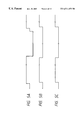
- FIGS. 5A to 5 C are timing charts each showing a sequence in a normal mode in the invention.
- FIGS. 6A to 6 C are diagrams showing pulse waveforms which are used in the invention.
- FIGS. 7A to 7 D are timing charts showing a sequence in the continuous magnify-record mode or density fluctuation prevent mode in the invention.
- FIG. 8 is a flowchart showing the operation in an embodiment 4.
- FIG. 9 is a graph showing the relation between the pulse width of a non-ejection pulse and its optimum applying time in the invention.
- FIG. 10 is a block diagram of an embodiment 2
- FIG. 11 is a block diagram of an embodiment 4.
- FIGS. 12A and 12B are explanatory diagrams of a boundary blur
- FIG. 13 is a graph showing a correction table of a boundary image signal
- FIG. 14 is a graph showing a table indicating a correspondence relation between T in the embodiment 4 and the correction table
- FIG. 15 is a flowchart showing the operation in the embodiment 4.
- FIG. 16 is a diagram showing a table indicating the correspondence relation between T in an embodiment 7 and the correction table.
- FIGS. 17A to 17 D are diagrams showing other correction tables of a boundary image signal.
- FIG. 1 is a control block diagram showing an embodiment 1 of the invention.
- Reference numerals 12 a , 12 b , and 12 c denote image signals of red (R), green (G), and blue (B) which are sent from an original image reader 11 or a computer.
- Reference numeral 13 denotes an image processor for executing image processes such as logarithm conversion, black extraction, UCR, masking, and the like; 14 a to 14 d image signals of cyan (C), magenta (M), yellow (Y), and black (Bk) which are generated from the image processor; 24 a to 24 d head driver circuits for generating pulses 25 a to 25 d ; 26 a to 26 d heads of cyan, magenta, yellow, and black; 27 a copy mode selecting switch for selecting one of the normal copy mode and the continuous magnify-record mode; 28 a selecting signal (a); 29 a CPU; 31 an image control signal; 34 a drive control signal; 32 a carriage motor control signal; and 33 a carriage motor.
- C cyan
- M magenta
- Y yellow
- Bk black
- each of the driver circuits 24 a to 24 d In the normal copy mode, each of the driver circuits 24 a to 24 d generates a pulse of a voltage 25V and a width 10 ⁇ sec only when the image signal is input. Each of the heads 26 a to 26 d heats an electrothermal transducer by such a pulse and causes a film boiling of the ink, thereby ejecting the ink.
- FIG. 2 is a perspective view of such a recording apparatus.
- a recording material 5 wound like a roll is conveyed by conveying rollers 1 and 2 and is sandwiched by a feed roller 3 and is sent in an (f) direction in association with the driving of a subscanning motor 10 coupled with the feed roller 3 .
- Guide rails 6 and 7 are disposed in parallel so as to traverse the recording material.
- a recording head unit 9 mounted on a carriage 8 is reciprocated to the right and left along the guide rails 6 and 7 .
- Heads 9 Y to 9 Bk (corresponding to 26 a to 26 d in FIG. 1) of four colors of yellow, magenta, cyan, and black are installed on the carriage 8 .
- Ink tanks of four colors are attached to those heads, respectively.
- the recording material 5 is intermittently fed by a length corresponding to a print width of the head 9 at a time. While the recording material 5 is stopped, the head is scanned (main scan) in the P direction and ejects an ink droplet according to the image signal.
- the number of nozzles of the head is set to 256 and a recording density is set to 400 dots/inch (dpi).
- a print width in the (f) direction is set to 16.256 mm.
- a print width in the P direction is set to 594 mm.
- FIG. 4 is a partial perspective view showing schematically a structure of an ink ejecting portion of the recording head 9 of a printer 23 .
- a plurality of ejection outlets 82 are formed at a predetermined pitch in an ejection outlet surface 81 which faces the recording material 5 at a predetermined gap.
- An electrothermal transducer 85 to generate an energy for ejecting the ink is provided along the wall surface of each liquid passage 84 communicating a common liquid chamber 83 and each ejection outlet 82 .
- the recording head 9 is installed in such a direction that the ejection outlets 82 are arranged so as to perpendicularly cross the scanning direction of the carriage 8 .
- the corresponding electrothermal transducer 85 On the basis of the image signal or ejecting signal, the corresponding electrothermal transducer 85 is driven and a film boiling is caused in the ink in the liquid passage 84 , thereby ejecting the ink from the ejection outlet 82 by a pressure that is generated in this instance.
- FIGS. 5A to 5 C are timing charts for various control signals shown in FIG. 1 .
- FIG. 5A shows a control signal of the carriage motor 33 . The carriage is scanned in the P direction by a positive signal and is scanned in the direction opposite to the P direction by a negative signal.
- FIG. 5B shows the image control signal 31 . Only when the image control signal 31 is ON, the image signals 14 a to 14 d are generated.
- FIG. 5C shows the drive control signal 34 .
- the drive control signal 34 When the drive control signal 34 is positive, the head driving pulse becomes a pulse suitable for ejection of the ink as shown in FIG. 6 A.
- conditions such that the voltage is set to 25V and the pulse width is set to 10 ⁇ sec are set as mentioned above.
- the carriage motor 33 repeats the forward and reverse rotations, so that the carriage 8 executes the reciprocating operation.
- the image control signal 31 is turned on and an image is recorded.
- Each of the head driver circuits 24 a to 24 d is constructed so as to generate the pulse suitable for ejection of the ink only when the drive control signal 34 is positive. Such a pulse is generated only when the image is recorded. A normal copy image is formed by such a sequence.
- FIGS. 7A to 7 D a timing chart as shown in FIGS. 7A to 7 D is derived.
- the carriage motor control signal 32 in FIG. 7 A and the image control signal 31 in FIG. 7B are the same as those in the normal copy mode.
- the drive control signal 34 in FIG. 7C is substantially the same as that in the normal copy mode when the image is formed, its polarity is inverted when the image formation of one scan is finished.
- the negative drive control signal 34 namely, at the time of the carriage return, a driving pulse of a short width is generated as shown in FIG. 6 B. Conditions for such a short driving pulse are set in a range such that it is insufficient to eject the ink. In case of the embodiment, the pulse width is set to 4 ⁇ sec.
- step S 11 the CPU 29 sends the drive control signal 34 according to the set signal (copy mode) 28 from the select switch 27 to the driver circuits 24 a to 24 d .
- steps S 12 and S 13 the driver circuits 24 a to 24 d set the conditions of the driving pulses at the end of the image formation, namely, at the time of the carriage return in accordance with the drive control signal 34 . That is, in the normal copy mode, a non-heat mode (step S 12 ) is set. In the continuous magnify-record mode, a heat mode in which the driving pulse (step S 13 ) of FIG. 6B is output is set.
- the image width is set to 594 mm as mentioned above.
- a length of image control signal 31 is set to
- the time of the carriage return (back scan) is faster than the above time and is equal to about 1.3 sec.
- the non-ejection pulse for heating is set to 4 ⁇ sec
- the non-ejection pulse is continuously applied for a period of time of 1.3 sec during the back scan as shown in FIG. 7 C.
- the applying time is shorter than 1.3 sec, the effect is insufficient.
- FIG. 9 is a graph showing an example of the relation obtained as mentioned above. Since it differs depending on the head structure or the like, it is desirable to obtain the proper relation each time the apparatus is designed.
- the pulse of a duration such as not to eject the ink is applied to the electrothermal transducer of the head as mentioned above, so that the head temperature doesn't decrease. Therefore, the image density at the starting edge of the next scan doesn't decrease. Even in the case where the copies are combined as shown in FIG. 3, the density difference can be suppressed to a level such that the joint portions are inconspicuous.
- the select switch is used to select the continuous magnify-record mode and, when such a mode is selected, the image data is controlled so as to correspond to the continuous magnify-record.
- the image data is controlled so as to correspond to the continuous magnify-record.
- the reading position on the original and the magnification are controlled.
- the location of the image data and the magnification are controlled.
- the embodiment 2 independently has the continuous magnify-record mode and the density fluctuation prevent mode.
- FIG. 10 is a block diagram of the embodiment 2, in which the same component elements as those shown in FIG. 1 are designated by the same reference numerals.
- reference numeral 35 denotes a select switch of the density fluctuation prevent mode and 36 indicates the selecting signal (b).
- the copy mode select switch 27 is used to merely select whether the copying operation is performed in which one of the continuous magnify-record mode and the normal copy mode. That is, whether the heat pulse of a duration such as not to eject the ink is given for a period of time during which no ink is ejected is not selected by the switch 27 .
- the heat pulse is selected by the density fluctuation prevent mode select switch 35 and is given only when the switch 35 is ON. Therefore, the density difference can be reduced as necessary even in a mode other than the continuous magnify-record mode. In addition, when an original which hardly causes a density difference even in the continuous magnify-record mode is used, there is no need to perform the unnecessary head heating operation. Thus, the life of the head is not unnecessarily reduced.
- a pulse of a short width has been used as a heat pulse which doesn't eject the ink.
- the range of the pulse width such as not to eject the ink is narrow and the head cannot be sufficiently heated.
- a standard pulse for ejecting the ink is equal to 10 ⁇ sec
- the heat pulse is set to about 5 ⁇ sec
- a boiling of the ink occurs and the ink is ejected, so that there is a case where the recording paper becomes dirty. Therefore, the pulse conditions such that the head can be heated are limited.
- the embodiment intends to cope with such a problem and devises a heat pulse waveform which doesn't eject the ink.
- the inventors of the present invention examined various pulse waveforms, so that they have found out that by dividing the waveform as shown in FIG. 6C, a larger energy can be applied without ejecting the ink.
- a waveform such that the ON state of 1 ⁇ sec and the OFF state of 1 ⁇ sec are repeated is used. By using such a waveform, even when a pulse of total 6 ⁇ sec is given, no ink is ejected and the head can be more efficiently heated.
- the head heat pulse of a short width has been used.
- the invention is not limited to such a pulse but the invention can be also similarly embodied even by using a pulse of a low voltage.
- the embodiment has been described above with respect to an example in which the head heat pulse is applied in the continuous magnify-record mode, the invention is not necessarily limited to the continuous magnify-record mode but can be also embodied in another copy mode in which the density change is conspicuous.
- the recording head 9 is scanned (main scan) in the A direction and the image recording of only a width (d) is sequentially repeated in accordance with the order of ( 1 ), ( 2 ), and ( 3 ) in the diagram.
- the width (d) is decided by the number of nozzles of the head and the recording density and is set to 16.256 mm in case of 256 nozzles and 400 dots/inch.
- the ink is blurred and the width of the recorded image is equal to d+ ⁇ d.
- the scan width in the B direction is equal to (d) in this instance, the image is overlapped by only ⁇ d and a banding occurs as shown in FIG. 12 B.
- the scan width is previously set to d ⁇ d, a white line occurs in a low density portion of a small ejection ink amount.
- the inventors of the present invention have proposed image recording apparatuses such that, when the image signal existing in the boundary portion of the serial scan is large, its image signal value is corrected to a small value, thereby preventing the banding in the high density portion in the specification of U.S. Pat. No. 5,225,849 (JP-A-2-3326, JP-A-2-25338), JP-A-2-219659, JP-A-2-265749, and the like.
- an amount of ink to be printed in the boundary portion is judged.
- an amount of ink to be printed in the boundary portion is small, no banding is formed due to the blur. Therefore, no process is particularly performed to the signal in the boundary portion.
- the ink amount of the boundary portion is large, by reducing the signal that is printed in the boundary portion, the blur is-suppressed, thereby preventing the banding.
- a degree of reduction of the signal in the boundary portion is determined in accordance with the amount of ink to be printed in the boundary portion.
- the ink temperature in case of recording in the normal mode obviously differs from the ink temperature in the case where the recording is performed while heating the head by applying the non-ejection pulse.
- a change in ink temperature causes a change in ink viscosity, so that the ejection amount changes.
- the ejection amount changes, the blur on the recording material changes and the banding in the boundary portion also changes.
- the embodiment is made to solve the above problem and by controlling the correction amount of the image signal to be recorded by the nozzles in the boundary portion in each scan in accordance with the applying conditions of the non-ejection pulse, even in case of applying the non-ejection pulse to the head, the image of a small banding in the boundary portion in the scan can be obtained.
- FIG. 11 is a block diagram showing an embodiment 4 and the portions having the functions corresponding to those in FIG. 1 are designated by the same reference numerals.
- reference numeral 11 denotes the original image reader for reading the original image
- 12 read signals of red (R), green (G), and blue (B)
- 13 an image processor for performing image processes such as logarithm conversion, black extraction, UCR, masking, and the like
- 14 color signals of cyan (C), magenta (M), yellow (Y), and black (Bk) which are obtained after completion of the image processes
- 15 a gamma ( ⁇ ) correction unit to perform a gradation correction
- 16 color signals obtained after completion of the gradation correction
- 17 a head non-uniformity correction unit to correct a density non-uniformity of the printing head
- 18 image signals after completion of the non-uniformity
- 19 a boundary blur correction unit
- 20 image signals after completion of the boundary blur correction
- 21 a binarizing unit
- 22 image signals
- the image reader 11 reads the original image and sends three color signals of R, G, and B to the image processor 13 .
- the image processor 13 executes the foregoing image processes to the color signals and generates the image signals 16 of C, M, Y, and Bk.
- the head non-uniformity correction unit 17 performs a correction such as to set off the non-uniformity characteristics of the head to the image signals 16 . For example, in case of the image signal to be printed by the nozzle of a large ink ejection amount, its value is reduced. In case of the signal to be printed by the nozzle of a small ink ejection amount, its value is increased.
- Reference numeral 18 denotes the signals after completion of the non-uniformity correction.
- the boundary blur correction unit 19 executes a blur correcting process to the signals 18 as will be explained in detail hereinlater.
- Reference numeral 20 denotes the signals after completion of the blur correction.
- the signals 20 are sent to the binarizing unit 21 and are binarized by a method such as dither method, error diffusion method, or the like.
- Reference numeral 22 denotes the image signals after completion of the binarization.
- the signals 22 are sent to the printer 23 , by which an image is recorded.
- the image signal which is printed by the boundary portion by the scan is obtained by a calculation. That is, now assuming that the color signals to be printed by the nozzles in the boundary portion are set to Ce, Me, Ye, Bke,
- the first nozzle and the 256th nozzle are used as nozzles in the boundary portion.
- the number of nozzles which are used is equal to 128, the first nozzle and the 128th nozzle are used in the odd-number designated scan, while the 129th nozzle and the 256th nozzle are used in the even-number designated scan.
- the first nozzle and the 64th nozzle are used in the first scan
- the 65th nozzle and the 128th nozzle are used in the second scan
- the 129th nozzle and the 192nd nozzle are used in the third scan
- the 193rd nozzle and the 256th nozzle are used in the fourth scan.
- the nozzles which are used for calculations are not always limited to only those nozzles but a range which exerts an influence on the banding in the boundary portion can be also experimentally obtained.
- the image signals in a range of every two nozzles in each of the upper and lower portions from the boundary portion are used for the calculations.
- Reference characters (a, b, c, d) denote weight coefficients and are also experimentally obtained.
- Each of Ce, Me, Ye, and Bke has a value within a range from 0 to 255.
- T has a value in a range from 0 to 1020.
- FIG. 13 shows the table in which 51 straight lines having inclinations of 1.0 to 0 are stored at regular intervals. Which one of the lines is selected is determined in accordance with the value of T. For example, when the value of T is equal to or less than T 0 , no correction is performed and the signal is directly output on the basis of the straight line of the inclination 1.0. When the value of T exceeds T 0 , however, the inclination is decreased in accordance with the value of T. Namely, a correction amount is increased so as to further reduce the density of the image signal.
- the correspondence relation between the value of T and the straight lines are previously set in an ROM.
- the straight lines are numbered in a manner such that the straight line of the inclination 0 is set to No. 1 , the straight line of the inclination 0.2 is set to No. 2 , the straight line of the inclination 0.4 is set to No. 3 , . . . , and the straight line of the inclination 1.0 is set to No. 51 .
- Such a relation is set into an ROM or RAM in which the value of T is set to the address input and the straight line No. is set to the output data.
- the table of FIG. 13 is set into another ROM or RAM in which the inclination can be selected by an output of the ROM or RAM.
- the image signal corresponding to the boundary nozzle is input into such an ROM or RAM, thereby performing the correction.
- the same nozzle as that used when obtaining T can be used.
- four nozzles of the first, second, 255th, and 256th nozzles are used to obtain T and two nozzles of the first and 256th nozzles can be also used to perform the correction.
- the mode setting unit 27 is an operating unit for setting the normal copy mode and continuous magnify-record mode and, further, for setting the copy magnification, recording paper size, original size, and the like.
- the user sets the recording conditions.
- the setting signal 28 is sent to the CPU 29 and the blur correction control signal 30 according to the mode is sent to the blur correction unit 19 .
- the blur correction unit 19 resets the weight coefficients in accordance with the blur correction control signal 30 .
- the drive control signal 34 is sent to the driver circuits ( 24 a to 24 d in FIG. 1) of the printer 23 .
- the driver circuits 24 a to 24 d set the heat mode in accordance with the drive control signal 34 .
- the weight coefficients are changed in accordance with the heat mode.
- the weight coefficients which are used in the correction calculation are changed simultaneously with the setting of the heat mode.
- the value of T in the continuous magnify-record mode is set to be larger than that in the normal mode and the correction amount is also set to a large value.
- the density difference when the continuous enlarged images are combined can be reduced.
- the correction amount to the image signal in the boundary portion is increased, thereby enabling the banding in the scan boundary portion to be also reduced.
- step S 21 the CPU 29 sends the drive control signal 34 according to the setting signal (copy mode) 28 from the select switch 27 to the driver circuits 24 a to 24 d of the printer 23 .
- steps S 22 and S 23 the driver circuits 24 a to 24 d set the conditions of the driving pulse at the end of the image formation, namely, at the time of the carriage return in accordance with the drive control signal 34 .
- the non-heat mode step S 22
- step S 23 the heat mode in which the driving pulse (step S 23 ) in FIG. 6B is set.
- the CPU 29 sends the blur correction control signal 30 according to the setting signal (copy mode) 28 from the mode setting unit 27 to the boundary blur correction unit 19 .
- the boundary blur correction unit 19 sets the weight coefficients a 1 , b 1 , c 1 , d 1 , a 2 , b 2 , c 2 , and d 2 in accordance with the blur correction control signal 30 .
- the value of T is calculated on the basis of the set weight coefficients and the color signals of the boundary portion.
- the conversion table (straight line number) of FIG. 13 corresponding to the value of T is selected in accordance with FIG. 14 .
- the conversion according to the conversion table in FIG. 13 selected in step S 27 for the color signals to the boundary nozzle is executed.
- step S 29 the above processes are repeated until the recording of one page is finished.
- the embodiment relates to the case where the non-ejection pulse is not applied at the time of the non-printing mode but is applied during the image formation.
- the image is recorded by using all of the 256 nozzles in the normal scan.
- the length (297 mm) of the A 4 size is not an integer times as large as the width (16.256 mm) of one scan, it is necessary to adjust the length for one scan.
- the printing width of the scan to adjust the length is equal to
- the embodiment intends to control the blur correction amount in such a scan.
- a block construction of the embodiment is substantially similar to that in FIG. 11 except that the weight coefficients are changed at the time of the scan for performing the length adjustment.
- the CPU 29 calculates the number of nozzles which are used in the length adjustment scan from the magnification, size of recording paper, and size of original which were set by the mode setting unit 27 . In accordance with the result of the calculation, the CPU 29 applies the non-ejection pulse to the nozzles which are not used and also controls the weight coefficients at the time of the length adjustment scan.
- the relation between the number of nozzles to be used and the weight coefficients is previously obtained by experiments. Even in case of applying the non-ejection pulse during one image formation as mentioned above, the banding in the boundary portion can be reduced.
- An embodiment 6 intends to perform a blur correction in the embodiment 3 in which the waveform of the non-ejection pulse is changed.
- the waveform such that the ON state of 1 ⁇ sec and the OFF state of 1 ⁇ sec are repeated, even by applying the pulse of total 6 ⁇ sec, no ink is ejected and the head can be more efficiently heated.
- the optimum calculation coefficients are obtained and the weight coefficients are changed to those optimum coefficients in the mode for applying the non-ejection pulse mentioned above, an image of a small boundary banding is obtained in a manner similar to each of the above embodiments.
- the weight coefficients have been controlled as means for controlling the blur correction amount.
- the correction amount is controlled by changing the correspondence relation between the correction table and the value of T.
- the embodiment 7 has a block construction that is substantially similar to that in FIG. 11 except that the blur correction unit 19 prepares a plurality of correspondence relations between the calculation result T and the correction table and controls the correspondence relation in accordance with the blur correction signal 30 , thereby controlling the blur correction.
- FIG. 16 shows the correspondence relations between T and the correction table in this case.
- One of the correspondence relations 1 to 50 is selected in accordance with the heat mode (copy mode).
- the relation such as to decrease T 0 and to enlarge the correction is selected.
- T 0 of the correspondence relation 1 is smaller than that of the correspondence relation 50 , the correction amount to reduce the ejection amount is large.
- FIGS. 17A to 17 D show correction curves in this case.
- a plurality of curves from (A) of a small correction ratio to (D) of a large correction ratio are prepared.
- the curve (D) is selected.
- the table of a small correction ratio is selected like (C) ⁇ (B) ⁇ (A).
- the correction curve is set to be non-linear, thereby correcting in a manner such that when the input signal is large, the output is set to be smaller.
- the algorithm of the blur correction, structure of the ink jet recording apparatus, structure of the head, waveform of the non-ejection pulse, and the like are not limited to those shown in the above embodiments 4 to 7.
- the piezoelectric type ink jet head is used and the ink ejection amount is directly modulated in an analog manner.
- the invention can be also similarly embodied even when a pulse of a dropped voltage is used as a non-ejection pulse.
- the present invention is particularly suitable for use in an ink jet recording head and a recording apparatus wherein a thermal energy generated by an electrothermal transducer, a laser beam, or the like is used to cause a change of state of the ink to eject or discharge the ink. This is because the high density of the picture elements and the high resolution of the recording are possible.
- the typical structure and the operational principle of such devices are preferably the ones disclosed in U.S. Pat. Nos. 4,723,129 and 4,740,796.
- the principle and structure are applicable to a so-called on-demand type recording system and a continuous type recording system.
- it is suitable for the on-demand type because the principle is such that at least one driving signal is applied to an electrothermal transducer disposed on a liquid (ink) retaining sheet or liquid passage, the driving signal being enough to provide such a quick temperature rise beyond a departure from nucleation boiling point, by which the thermal energy is provided by the electrothermal transducer to produce film boiling on the heating portion of the recording head, whereby a bubble can be formed in the liquid (ink) corresponding to each of the driving signals.
- the liquid (ink) is ejected through an ejection outlet to produce at least one droplet.
- the driving signal is preferably in the form of a pulse, because the development and contraction of the bubble can be effected instantaneously, and therefore, the liquid (ink) is ejected with quick response.
- the driving signal in the form of the pulse is preferably such as disclosed in U.S. Pat. Nos. 4,463,359 and 4,345,262.
- the temperature increasing rate of the heating surface is preferably such as disclosed in U.S. Pat. No. 4,313,124.
- the structure of the recording head may be as shown in U.S. Pat. Nos. 4,558,333 and 4,459,600 wherein the heating portion is disposed at a bent portion, as well as the structure of the combination of the ejection outlet, liquid passage and the electrothermal transducer as disclosed in the above-mentioned patents.
- the present invention is applicable to the structure disclosed in Japanese Laid-Open Patent Application No. 59-123670 wherein a common slit is used as the ejection outlet for plural electrothermal transducers, and to the structure disclosed in Japanese Laid-Open Patent Application No. 59-138461 wherein an opening for absorbing pressure waves of the thermal energy is formed corresponding to the ejecting portion. This is because the present invention is effective to perform the recording operation with certainty and at high efficiency regardless of the type of recording head.
- the present invention is applicable to a serial type recording head wherein the recording head is fixed on the main assembly, to a replaceable chip type recording head which is connected electrically with the main apparatus and which can be supplied with the ink when it is mounted in the main assembly, or to a cartridge type recording head having an integral ink container.
- the provisions of the recovery means and/or the auxiliary means for the preliminary operation are preferable, because they can further stabilize the effects of the present invention.
- Examples of such means include capping means for the recording head, cleaning means therefore, pressing or sucking means, preliminary heating means which may be the electrothermal transducer, an additional heating element or a combination thereof.
- preliminary heating means which may be the electrothermal transducer, an additional heating element or a combination thereof.
- means for effecting preliminary ejection (not for the recording operation) can stabilize the recording operation.
- the recording head mountable may be a single head corresponding to a single color ink, or may be plural heads corresponding to the plurality of ink materials having different recording colors or densities.
- the present invention is effectively applied to an apparatus having at least one of a monochromatic mode mainly with black, a multi-color mode with different color ink materials and/or a full-color mode using the mixture of the colors, which may be an integrally formed recording unit or a combination of plural recording heads.
- the ink has been liquid. It also may be ink material which is solid below the room temperature but liquid at room temperature. Since the ink is kept within a temperature between 30° C. and 70° C., in order to stabilize the viscosity of the ink to provide the stabilized ejection in the usual recording apparatus of this type, the ink may be such that it is liquid within the temperature range when the recording signal is the present invention is applicable to other types of ink. In one of them, the temperature rise due to the thermal energy is positively prevented by consuming it for the state change of the ink from the solid state to the liquid state. Another ink material is solidified when it is left, to prevent the evaporation of the ink.
- the ink in response to the application of the recording signal producing thermal energy, the ink is liquefied, and the liquefied ink may be ejected.
- Another ink material may start to be solidified at the time when it reaches the recording material.
- the present invention is also applicable to such an ink material as is liquefied by the application of the thermal energy.
- Such an ink material may be retained as a liquid or solid material in through holes or recesses formed in a porous sheet as disclosed in Japanese Laid-Open Patent Application No. 54-56847 and Japanese Laid-Open Patent Application No. 60-71260.
- the sheet is faced to the electrothermal transducers.
- the most effective one of the techniques described above is the film boiling system.
- the ink jet recording apparatus may be used as an output terminal of an information processing apparatus such as computer or the like, as a copying apparatus combined with an image reader or the like, or as a facsimile machine having information sending and receiving functions.
- the non-ejection pulse under conditions such as not to eject the ink is applied to the head in the non-print mode, so that the non-uniformity of the image density can be suppressed and the decrease in life of the head can be minimized.
Priority Applications (1)
| Application Number | Priority Date | Filing Date | Title |
|---|---|---|---|
| US08/861,003 US6511159B1 (en) | 1993-09-24 | 1997-05-21 | Ink jet recording apparatus and recording method |
Applications Claiming Priority (4)
| Application Number | Priority Date | Filing Date | Title |
|---|---|---|---|
| JP23802093A JP3376036B2 (ja) | 1993-09-24 | 1993-09-24 | インクジェット記録装置及び記録方法 |
| JP5-238020 | 1993-09-24 | ||
| US31149494A | 1994-09-23 | 1994-09-23 | |
| US08/861,003 US6511159B1 (en) | 1993-09-24 | 1997-05-21 | Ink jet recording apparatus and recording method |
Related Parent Applications (1)
| Application Number | Title | Priority Date | Filing Date |
|---|---|---|---|
| US31149494A Continuation | 1993-09-24 | 1994-09-23 |
Publications (1)
| Publication Number | Publication Date |
|---|---|
| US6511159B1 true US6511159B1 (en) | 2003-01-28 |
Family
ID=17023971
Family Applications (1)
| Application Number | Title | Priority Date | Filing Date |
|---|---|---|---|
| US08/861,003 Expired - Lifetime US6511159B1 (en) | 1993-09-24 | 1997-05-21 | Ink jet recording apparatus and recording method |
Country Status (2)
| Country | Link |
|---|---|
| US (1) | US6511159B1 (ja) |
| JP (1) | JP3376036B2 (ja) |
Cited By (1)
| Publication number | Priority date | Publication date | Assignee | Title |
|---|---|---|---|---|
| US20080218547A1 (en) * | 2007-03-06 | 2008-09-11 | Canon Kabushiki Kaisha | Ink jet printing apparatus and ink jet printing method |
Citations (35)
| Publication number | Priority date | Publication date | Assignee | Title |
|---|---|---|---|---|
| JPS5456847A (en) | 1977-10-14 | 1979-05-08 | Canon Inc | Medium for thermo transfer recording |
| US4313124A (en) | 1979-05-18 | 1982-01-26 | Canon Kabushiki Kaisha | Liquid jet recording process and liquid jet recording head |
| US4345262A (en) | 1979-02-19 | 1982-08-17 | Canon Kabushiki Kaisha | Ink jet recording method |
| JPS58187464A (ja) | 1982-04-28 | 1983-11-01 | Asahi Chem Ind Co Ltd | 粉体塗料用樹脂組成物 |
| JPS58187364A (ja) | 1982-04-27 | 1983-11-01 | Canon Inc | 液体噴射記録装置 |
| US4459600A (en) | 1978-10-31 | 1984-07-10 | Canon Kabushiki Kaisha | Liquid jet recording device |
| JPS59123670A (ja) | 1982-12-28 | 1984-07-17 | Canon Inc | インクジエツトヘツド |
| US4463359A (en) | 1979-04-02 | 1984-07-31 | Canon Kabushiki Kaisha | Droplet generating method and apparatus thereof |
| JPS59138461A (ja) | 1983-01-28 | 1984-08-08 | Canon Inc | 液体噴射記録装置 |
| JPS6071260A (ja) | 1983-09-28 | 1985-04-23 | Erumu:Kk | 記録装置 |
| US4558333A (en) | 1981-07-09 | 1985-12-10 | Canon Kabushiki Kaisha | Liquid jet recording head |
| US4712172A (en) * | 1984-04-17 | 1987-12-08 | Canon Kabushiki Kaisha | Method for preventing non-discharge in a liquid jet recorder and a liquid jet recorder |
| US4723129A (en) | 1977-10-03 | 1988-02-02 | Canon Kabushiki Kaisha | Bubble jet recording method and apparatus in which a heating element generates bubbles in a liquid flow path to project droplets |
| JPH023326A (ja) | 1988-06-17 | 1990-01-08 | Canon Inc | 画像記録装置 |
| JPH0225338A (ja) | 1988-07-14 | 1990-01-26 | Canon Inc | 画像記録装置 |
| JPH02219659A (ja) | 1989-02-20 | 1990-09-03 | Canon Inc | 画像形成装置 |
| JPH02265749A (ja) | 1989-04-07 | 1990-10-30 | Canon Inc | 画像処理方法 |
| US4982199A (en) * | 1988-12-16 | 1991-01-01 | Hewlett-Packard Company | Method and apparatus for gray scale printing with a thermal ink jet pen |
| US5109234A (en) * | 1990-09-14 | 1992-04-28 | Hewlett-Packard Company | Printhead warming method to defeat wait-time banding |
| US5132702A (en) * | 1989-02-08 | 1992-07-21 | Canon Kabushiki Kaisha | Liquid jet recording apparatus and method |
| US5157411A (en) * | 1990-02-02 | 1992-10-20 | Canon Kabushiki Kaisha | Recording head and a recording device utilizing the recording head |
| US5168284A (en) * | 1991-05-01 | 1992-12-01 | Hewlett-Packard Company | Printhead temperature controller that uses nonprinting pulses |
| US5172134A (en) * | 1989-03-31 | 1992-12-15 | Canon Kabushiki Kaisha | Ink jet recording head, driving method for same and ink jet recording apparatus |
| US5225849A (en) * | 1988-06-17 | 1993-07-06 | Canon Kabushiki Kaisha | Image recording apparatus and method for performing recording by making ink adhere to a recording medium and incorporating image data correction |
| US5276459A (en) | 1990-04-27 | 1994-01-04 | Canon Kabushiki Kaisha | Recording apparatus for performing uniform density image recording utilizing plural types of recording heads |
| US5285220A (en) | 1989-11-22 | 1994-02-08 | Canon Kabushiki Kaisha | Image recording apparatus with tone correction for individual recording heads |
| US5300969A (en) * | 1990-02-02 | 1994-04-05 | Canon Kabushiki Kaisha | Ink jet recording method and apparatus for maintaining efficient ink viscosity |
| US5302971A (en) | 1984-12-28 | 1994-04-12 | Canon Kabushiki Kaisha | Liquid discharge recording apparatus and method for maintaining proper ink viscosity by deactivating heating during capping and for preventing overheating by having plural heating modes |
| US5339098A (en) | 1984-02-21 | 1994-08-16 | Canon Kabushiki Kaisha | Liquid discharge recording apparatus having apparatus for effecting preparatory emission |
| US5381164A (en) * | 1988-07-01 | 1995-01-10 | Canon Kabushiki Kaisha | Recording method and apparatus for preheating a thermally activated printing read |
| US5594478A (en) * | 1991-08-02 | 1997-01-14 | Canon Kabushiki Kaisha | Ink jet recording apparatus for divisionally driving a recording head with a plurality of ink jet orifices grouped into blocks |
| US5598190A (en) * | 1992-06-12 | 1997-01-28 | Canon Kabushiki Kaisha | Recording apparatus with standby control for thermal head |
| US5606355A (en) * | 1993-01-07 | 1997-02-25 | Fuji Xerox Co., Ltd. | Ink jet recording apparatus for adjusting recording mode based on number of recording heads |
| US5808632A (en) * | 1990-02-02 | 1998-09-15 | Canon Kabushiki Kaisha | Recording apparatus and method using ink jet recording head |
| US5894314A (en) * | 1991-01-18 | 1999-04-13 | Canon Kabushiki Kaisha | Ink jet recording apparatus using thermal energy |
-
1993
- 1993-09-24 JP JP23802093A patent/JP3376036B2/ja not_active Expired - Fee Related
-
1997
- 1997-05-21 US US08/861,003 patent/US6511159B1/en not_active Expired - Lifetime
Patent Citations (37)
| Publication number | Priority date | Publication date | Assignee | Title |
|---|---|---|---|---|
| US4740796A (en) | 1977-10-03 | 1988-04-26 | Canon Kabushiki Kaisha | Bubble jet recording method and apparatus in which a heating element generates bubbles in multiple liquid flow paths to project droplets |
| US4723129A (en) | 1977-10-03 | 1988-02-02 | Canon Kabushiki Kaisha | Bubble jet recording method and apparatus in which a heating element generates bubbles in a liquid flow path to project droplets |
| JPS5456847A (en) | 1977-10-14 | 1979-05-08 | Canon Inc | Medium for thermo transfer recording |
| US4459600A (en) | 1978-10-31 | 1984-07-10 | Canon Kabushiki Kaisha | Liquid jet recording device |
| US4345262A (en) | 1979-02-19 | 1982-08-17 | Canon Kabushiki Kaisha | Ink jet recording method |
| US4463359A (en) | 1979-04-02 | 1984-07-31 | Canon Kabushiki Kaisha | Droplet generating method and apparatus thereof |
| US4313124A (en) | 1979-05-18 | 1982-01-26 | Canon Kabushiki Kaisha | Liquid jet recording process and liquid jet recording head |
| US4558333A (en) | 1981-07-09 | 1985-12-10 | Canon Kabushiki Kaisha | Liquid jet recording head |
| JPS58187364A (ja) | 1982-04-27 | 1983-11-01 | Canon Inc | 液体噴射記録装置 |
| JPS58187464A (ja) | 1982-04-28 | 1983-11-01 | Asahi Chem Ind Co Ltd | 粉体塗料用樹脂組成物 |
| JPS59123670A (ja) | 1982-12-28 | 1984-07-17 | Canon Inc | インクジエツトヘツド |
| JPS59138461A (ja) | 1983-01-28 | 1984-08-08 | Canon Inc | 液体噴射記録装置 |
| US4608577A (en) | 1983-09-28 | 1986-08-26 | Elm Co., Ltd. | Ink-belt bubble propulsion printer |
| JPS6071260A (ja) | 1983-09-28 | 1985-04-23 | Erumu:Kk | 記録装置 |
| US5339098A (en) | 1984-02-21 | 1994-08-16 | Canon Kabushiki Kaisha | Liquid discharge recording apparatus having apparatus for effecting preparatory emission |
| US4712172A (en) * | 1984-04-17 | 1987-12-08 | Canon Kabushiki Kaisha | Method for preventing non-discharge in a liquid jet recorder and a liquid jet recorder |
| US5302971A (en) | 1984-12-28 | 1994-04-12 | Canon Kabushiki Kaisha | Liquid discharge recording apparatus and method for maintaining proper ink viscosity by deactivating heating during capping and for preventing overheating by having plural heating modes |
| JPH023326A (ja) | 1988-06-17 | 1990-01-08 | Canon Inc | 画像記録装置 |
| US5225849A (en) * | 1988-06-17 | 1993-07-06 | Canon Kabushiki Kaisha | Image recording apparatus and method for performing recording by making ink adhere to a recording medium and incorporating image data correction |
| US5381164A (en) * | 1988-07-01 | 1995-01-10 | Canon Kabushiki Kaisha | Recording method and apparatus for preheating a thermally activated printing read |
| JPH0225338A (ja) | 1988-07-14 | 1990-01-26 | Canon Inc | 画像記録装置 |
| US4982199A (en) * | 1988-12-16 | 1991-01-01 | Hewlett-Packard Company | Method and apparatus for gray scale printing with a thermal ink jet pen |
| US5132702A (en) * | 1989-02-08 | 1992-07-21 | Canon Kabushiki Kaisha | Liquid jet recording apparatus and method |
| JPH02219659A (ja) | 1989-02-20 | 1990-09-03 | Canon Inc | 画像形成装置 |
| US5172134A (en) * | 1989-03-31 | 1992-12-15 | Canon Kabushiki Kaisha | Ink jet recording head, driving method for same and ink jet recording apparatus |
| JPH02265749A (ja) | 1989-04-07 | 1990-10-30 | Canon Inc | 画像処理方法 |
| US5285220A (en) | 1989-11-22 | 1994-02-08 | Canon Kabushiki Kaisha | Image recording apparatus with tone correction for individual recording heads |
| US5300969A (en) * | 1990-02-02 | 1994-04-05 | Canon Kabushiki Kaisha | Ink jet recording method and apparatus for maintaining efficient ink viscosity |
| US5157411A (en) * | 1990-02-02 | 1992-10-20 | Canon Kabushiki Kaisha | Recording head and a recording device utilizing the recording head |
| US5808632A (en) * | 1990-02-02 | 1998-09-15 | Canon Kabushiki Kaisha | Recording apparatus and method using ink jet recording head |
| US5276459A (en) | 1990-04-27 | 1994-01-04 | Canon Kabushiki Kaisha | Recording apparatus for performing uniform density image recording utilizing plural types of recording heads |
| US5109234A (en) * | 1990-09-14 | 1992-04-28 | Hewlett-Packard Company | Printhead warming method to defeat wait-time banding |
| US5894314A (en) * | 1991-01-18 | 1999-04-13 | Canon Kabushiki Kaisha | Ink jet recording apparatus using thermal energy |
| US5168284A (en) * | 1991-05-01 | 1992-12-01 | Hewlett-Packard Company | Printhead temperature controller that uses nonprinting pulses |
| US5594478A (en) * | 1991-08-02 | 1997-01-14 | Canon Kabushiki Kaisha | Ink jet recording apparatus for divisionally driving a recording head with a plurality of ink jet orifices grouped into blocks |
| US5598190A (en) * | 1992-06-12 | 1997-01-28 | Canon Kabushiki Kaisha | Recording apparatus with standby control for thermal head |
| US5606355A (en) * | 1993-01-07 | 1997-02-25 | Fuji Xerox Co., Ltd. | Ink jet recording apparatus for adjusting recording mode based on number of recording heads |
Cited By (1)
| Publication number | Priority date | Publication date | Assignee | Title |
|---|---|---|---|---|
| US20080218547A1 (en) * | 2007-03-06 | 2008-09-11 | Canon Kabushiki Kaisha | Ink jet printing apparatus and ink jet printing method |
Also Published As
| Publication number | Publication date |
|---|---|
| JP3376036B2 (ja) | 2003-02-10 |
| JPH0789070A (ja) | 1995-04-04 |
Similar Documents
| Publication | Publication Date | Title |
|---|---|---|
| EP0517543B1 (en) | Ink jet recording method | |
| US6260939B1 (en) | Tone recording method using ink jet recording head that records pixels using a plurality of liquid droplets | |
| EP0885732B1 (en) | Ink-jet printing method and apparatus | |
| US7296877B2 (en) | Ink jet printing apparatus and print position setting method | |
| JP4528481B2 (ja) | インク滴の大きさの誤差に応じてドットの記録率を変える印刷 | |
| JPH0976482A (ja) | インクジェット記録装置 | |
| EP0864424B1 (en) | Ink jet recording apparatus and method for controlling an amount of ink discharged after an inperruption in recording | |
| US6406114B1 (en) | Tonal product recorded by ink and having a plurality of pixels with plural tonal levels | |
| JP4638968B2 (ja) | テストパターン形成方法および記録装置 | |
| US5841451A (en) | Scan interval control in ink jet recording apparatus | |
| US5760798A (en) | Ink jet recording apparatus and method in which an amount of ink ejected is corrected according to a recording head state | |
| EP0517521B1 (en) | Tone recording method using ink jet recording head | |
| JPH0811298A (ja) | インクジェット記録方法及び記録装置 | |
| US7695088B2 (en) | Ink jet printing apparatus and ink jet printing method | |
| JPH11245384A (ja) | 記録装置および記録方法 | |
| JP3205082B2 (ja) | 画像形成方法及び装置 | |
| US6511159B1 (en) | Ink jet recording apparatus and recording method | |
| US20040165033A1 (en) | Ink jet printing apparatus and printing position setting method of the apparatus | |
| US8474941B2 (en) | Inkjet printing apparatus and inkjet printing method | |
| JP3251371B2 (ja) | 画像形成装置及びその方法 | |
| JPH1170645A (ja) | 画像記録装置およびその記録方法 | |
| JP2919641B2 (ja) | インクジェット記録方法 | |
| JPH07323536A (ja) | インクジェット記録装置およびインクジェット記録方法 | |
| US5808632A (en) | Recording apparatus and method using ink jet recording head | |
| JP2792579B2 (ja) | 記録装置 |
Legal Events
| Date | Code | Title | Description |
|---|---|---|---|
| STCF | Information on status: patent grant |
Free format text: PATENTED CASE |
|
| CC | Certificate of correction | ||
| FPAY | Fee payment |
Year of fee payment: 4 |
|
| FPAY | Fee payment |
Year of fee payment: 8 |
|
| FPAY | Fee payment |
Year of fee payment: 12 |